

Sony PCS-C150, PCS-C150P Service manual
PCS-C150/C150P
PCS-C150/C150P
SERVICE MANUAL
PCS-C150/PCS-C150P
System
Video signal PCS-C150 : NTSC standards
Picture element 1/3 inch color CCD
Lens Electromotion twelve fold zoom
Point-blank range WIDE end : 10mm
9-928-130-11
99E09008-1
Minimum illumination 7 lux (F1.8)/with 50IRE
Illumination range 7 to 100,000 lux
Shutter speed PCS-C150 : 1/60 to 1/10,000 (VISCA
Gain selector Automatic/manual
Horizontal resolution NTSC : 460 TV
Video S/N 48 dB
Pan/tilt action Horizontal : 100º, Vertical : 25º
PCS-C150P : PAL Color, CCIR
standards
(Total picture element number :
PCS-C150 : Approx. 410,000
PCS-C150P : Approx. 470,000)
(Effective picture element
number :
PCS-C150 : Approx. 380,000
PCS-C150P : Approx. 440,000)
lens
f=5.4 to 64.8mm, F1.8 to F2.7
Horizontal angle : 4.4º to 48.8º
TELE end : 800mm
control)
PCS-C150P : 1/50 to 1/10,000 (VISCA
control)
PAL : 450 TV
PCS-C150 (NTSC)
PCS-C150P (PAL)
SPECIFICATIONS
Input/output terminals
Processor terminal D-sub 15 pin
Output control terminal 8 pin mini DIN
General
Input voltage DC 12 to 14 V
Power consumption 11 W (Refference value)
Operating temperature 0º to 40º (32º to 104ºF)
Storage temperature – 20º to 60º (– 4º to 140ºF)
Dimensions Approx 142 × 109 × 162 mm
(w/h/d)
Mass Approx. 1,200 g (42.3 oz.)
9-928-130-11
Sony Corporation
Information Tec hnology Company
– 80 –
Printed in Japan C1999. 5
99E09008-1
Published by VAIO Custormer Link
COLOR VIDEO CAMERA
9-928-130-11
Y
Y
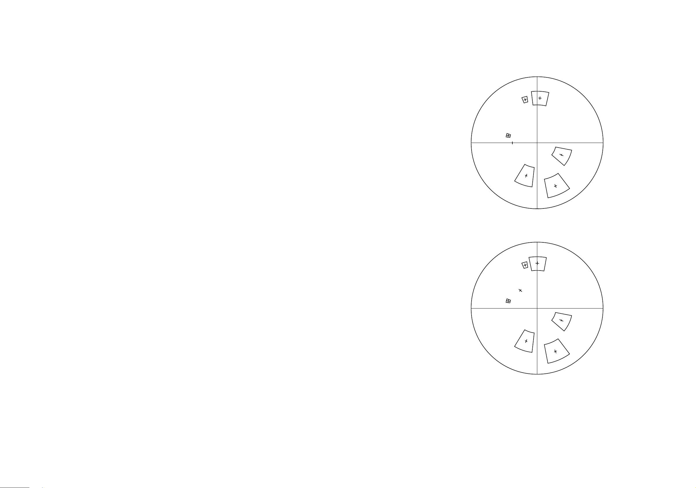
FOR CAMERA COLOR REPRODUCTION ADJUSTMENT
R
Y
L
G
R-Y
G
M
B-
B
C
Y
PCS-C150 (NTSC)
SAFETY CHECK-OUT
After correcting the original service problem, perform the following
safety checks before releasing the set to the customer :
1. Check the area of your repair for unsoldered or poorly-soldered
connections. Check the entire board surface for solder splashes
and bridges.
2. Check the interboard wiring to ensure that no wires are “pinched”
or contact high-wattage resistors.
3. Look for unauthorized replacement parts, particularly transis-
tors, that were installed during a previous repair. Point them out to
the customer and recommend their replacement.
SAFETY-RELATED COMPONENT WARNING!!
4. Look for parts which, though functioning, show obvious signs
of deterioration. Point them out to the customer and recommend
their replacement.
5. Check the line cord for cracks and abrasion. Recommend the
replacement of any such line cord to the customer.
6. Flexible Circuit Board Repairing
• Keep the temperature of the soldering iron around 270°C during
repairing.
• Do not touch the soldering iron on the same conductor of the cir
cuit board (within 3 times).
• Be careful not to apply force on the conductor when soldering or
unsoldering.
R-Y
G
R
Y
L
G
M
B-
B
C
Y
PCS-C150P (PAL)
COMPONENTS IDENTIFIED BY MARK ! OR DOTTED LINE
WITH MARK ! ON THE SCHEMATIC DIAGRAMS AND IN THE
PARTS LIST ARE CRITICAL TO SAFE OPERATION. REPLACE THESE COMPONENTS WITH SONY PARTS WHOSE
P ART NUMBERS APPEAR AS SHOWN IN THIS MANUAL OR
IN SUPPLEMENTS PUBLISHED BY SONY.
– 2 – – 79 –

TABLE OF CONTENTS
1. GENERAL
• Locations of Controls ............................................................ 1-1
• Precautions ............................................................................ 1-1
• Connections.........................................................................1-2E
• Turning on the Power ..........................................................1-2E
2. DISASSEMBLY
2-1. Camera Cabinet (Upper) ............................................... 2-1
2-2. Bottom Plate Assy......................................................... 2-1
2-3. Main Block.................................................................... 2-2
2-4. ID-11A (A) Board ......................................................... 2-2
2-5. Pan Base Assy ............................................................... 2-3
2-6. LI-55A (A) Board ......................................................... 2-3
2-7. Pan Cabinet ................................................................... 2-4
2-8. CCD Lens Assy............................................................. 2-4
2-9. Camera Cabinet (Lower)............................................... 2-5
2-10. Stepping Motor ............................................................. 2-5
2-11. LI-59A (A) Board ......................................................... 2-6
2-12. LD-84A (A)/84A (B) Board.......................................... 2-6
2-13. VC-179 (A)/179 (B) Board ........................................... 2-7
2-14. RS-67A (A)/LB-47A (A) Board ................................... 2-7
2-15. MD-68 (A) Board........................................................2-8E
2-16. Lens Block .................................................................. 2-8E
2-17. CD-154A (A) Board....................................................2-8E
2-18. CCD Fitting Adaptor (H) ............................................2-8E
4. BLOCK DIAGRAM/SCHEMATIC DIAGRAM
(Extra number: 9-928-130-41)
4-1. Overall Block Diagram ................................................... 4-1
4-2. Schematic Diagram
• This Note is Common for Schematic Diagrams ............... 4-3
4-2-1. CD-154A (A) Board .............................................. 4-3
4-2-2. LI-52A (A), LI-55A (A) and LI-59A (A) Boards.. 4-5
4-2-3. LD-84A (A)/84A (B) Board .................................. 4-7
4-2-4. RS-67A (A) Board, LB-47A (A) Board,
RM-77A (A) Board................................................ 4-9
4-2-5. VC-179 (A)/179 (B) Board (1/4) ......................... 4-11
4-2-6. VC-179 (A)/179 (B) Board (2/4) ......................... 4-13
4-2-7. VC-179 (A)/179 (B) Board (3/4) ......................... 4-15
4-2-8. VC-179 (A)/179 (B) Board (4/4) ......................... 4-17
4-2-9. MD-68 (A) Board ................................................ 4-20
4-2-10. ID-11A (A) Board................................................ 4-23
4-2-11. AT-21A (A) Board ............................................... 4-26
5. PRINTED WIRING BOARDS
5-1. Circuit Boards Location .................................................. 5-1
5-2. Printed Wiring Boards
• This Note is Common for Printed Wiring Boards ............. 5-2
• CD-154A (A) Board.......................................................... 5-2
• VC-179 (A)/179 (B) Board ............................................... 5-3
• MD-68 (A) and RS-67A (A) Boards................................. 5-5
• ID-11A (A) Boards ........................................................... 5-7
• AT-21A (A), LI-52A (A), LI-55A (A) and
LI-59A (A) Boards ............................................................ 5-9
• LD-84A (A)/84A (B) Board............................................ 5-11
• LB-47A (A) and RM-77A (A) Board ........................... 5-12E
6. ADJUSTMENTS
6-1. Preparation for Adjustment
6-1-1. List of Servicing Jigs ............................................ 6-1
6-1-2. Preparations .......................................................... 6-2
6-1-3. Precautions ........................................................... 6-5
6-1-4. Adjusting Remote Commander ............................ 6-6
6-1-5. Page D Address List ............................................. 6-7
6-1-6. Page F Address List .............................................. 6-9
6-1-7. Page 5 Address List ............................................ 6-12
6-1-8. Data Processing .................................................. 6-14
6-2. Camera System Adjustment
6-2-1. Power Supply Voltage Check.............................. 6-15
6-2-2. Page D Data Initialization................................... 6-15
6-2-3. Page D Data Modification 1 ............................... 6-15
6-2-4. Page F Data Initialization ................................... 6-15
6-2-5. Page F Data Modification................................... 6-15
6-2-6. 28 MHz Original Oscillation Adjustment........... 6-16
6-2-7. V SUB Adjustment ............................................. 6-16
6-2-8. VRG Adjustment ................................................ 6-16
6-2-9. Flange Back Adjustment..................................... 6-17
6-2-10. Flange Back Check ............................................. 6-17
6-2-11. Hall Adjustment .................................................. 6-18
6-2-12. Picture Frame Setting ......................................... 6-19
6-2-13. Color Reproduction Adjustment......................... 6-20
6-2-14. Iris IN/OUT Adjustment..................................... 6-21
6-2-15. Max Gain Adjustment......................................... 6-21
6-2-16. Auto White Balance Standard Data Input .......... 6-22
6-2-17. Auto White Balance Adjustment ........................ 6-22
6-2-18. White Balance Check ......................................... 6-23
6-2-19. VIDEO OUT Level Check ................................. 6-23
6-2-20. Page D Data Modification 2 ............................. 6-24E
6-2-21. Page 5 Data Initialization .................................6-24E
6-2-22. Home Position Adjustment............................... 6-24E
6-3. Electrical Block Check
6-3-1. Pan Tilter Operation Check .............................. 6-24E
7. VISCA COMMAND LIST
7-1. VISCA Summary ............................................................. 7-1
7-2. PCS-C150/C150P-VISCA Connection............................ 7-2
7-3. VISCA Communication Formats
7-3-1. VISCA Packet Structure .......................................... 7-2
7-3-2. Commands and Inquiries ...................................... 7-3
7-3-3. Responses to Commands and Inquiries ................ 7-3
7-3-4. Socket Number ..................................................... 7-3
7-3-5. Command Execution Stop .................................... 7-3
7-4. PCS-C150/C150P Setting Commands (Network setting)
7-4-1. VISCA Network Management Commands .......... 7-4
7-4-2. VISCA Interface Commands................................ 7-4
7-4-3. PCS-C150/C150P Functions ................................ 7-5
7-5. PCS-C150/C150P Commands ......................................... 7-6
7-6. PCS-C150/C150P Inquiry Command ............................ 7-10
7-7. Code List
7-7-1. Code list for Shutter, Iris, Gain and
Wide con lens ..................................................... 7-12
7-7-2. Code list for Pan/Tilter status,
AT mode status and MD mode status ................. 7-13
7-8. VISCA Communications Examples ............................7-14E
– 3 –

8. REPAIR PARTS LIST
8-1. Exploded Views
8-1-1. Camera Cabinet Section........................................... 8-1
8-1-2. Pan Base Section ...................................................... 8-2
8-1-3. Tilt Base Section ...................................................... 8-3
8-1-4. Lens Section ............................................................. 8-5
8-2. Electrical Parts List
• AT-21A (A) Board ............................................................ 8-6
• CD-154A (A) Board ......................................................... 8-6
• ID-11A (A) Board ............................................................ 8-7
• LB-47A (A) Board ........................................................... 8-8
• LD-84A (A)/84A (B) Board ............................................. 8-8
• LI-52A (A) Board ............................................................. 8-9
• LI-55A (A) Board ............................................................. 8-9
• LI-59A (A) Board ............................................................. 8-9
• MD-68 (A) Board ............................................................. 8-9
• RM-77A (A) Board ........................................................ 8-11
• RS-67A (A) Board.......................................................... 8-11
• VC-179 (A)/179 (B) Board ............................................ 8-12
• For Camera Color Reproduction Adjustment .................... 79
– 4 –
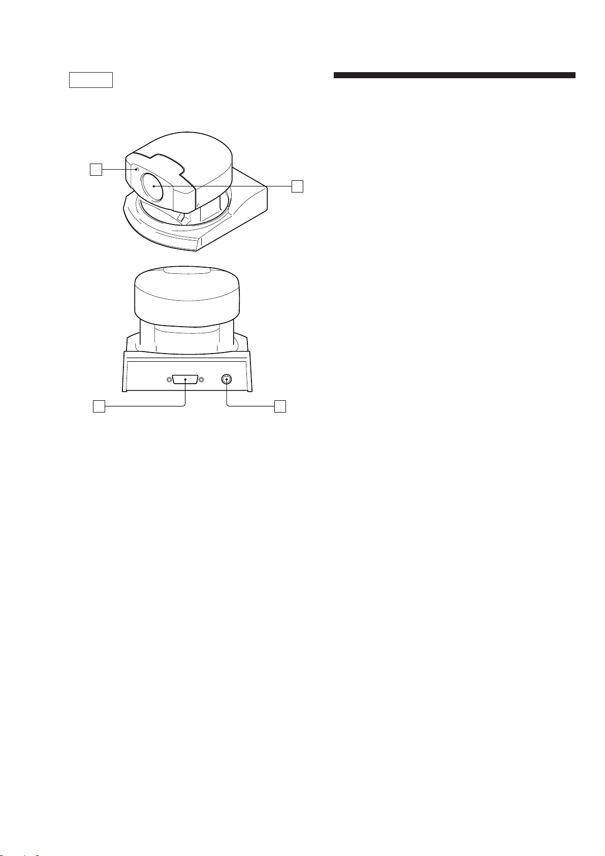
General
Locations of Controls
1
SECTION 1
GENERAL
Precautions
• After operating the unit with an AC power adaptor, disconnect the AC
power adaptor from the wall outlet if the set is not to be used for an extended period of time.
Brightness of a subject
Color Video Camera might not work with its best performance in a place
where brightness exceeds the illumination range (such as a place exposed to
2
direct sunlight).
Avoid specialized application
Avoid using Color Video Camera f or monitoring application where it would
be forced to focus on a stationary object for a long period of time. Also
avoid focusing the camera on an extremely bright object such as sunlight or
a fluorescent lamp. Otherwise the color filter might be damaged.
Precaution on copyright
Tele vision programs, pictures, magazines, and other materials may be copyrighted. Unauthorized recording or storing of such materials violates the
provision of the copyright laws.
PCS-C150/C150P
1 Caution lamp
2 Lens
3 VISCA OUT jack
4 PROCESSOR jack
34
1-1

Preparations
Input/Output
Conversion board
Connections
Be sure to use the tool board (J-2500-222-1) to connect to this unit.
Connect the power supply, connect the tool board to the unit, and connect
the terminals of the tool board to the personal computer, TV, or VCR equipped
with an S-Video input. Some connections may require e xtra cables. Refer to
the instructions manual of the equipment to be connected.
S-VIDEO cable
(not supplied)
to S VIDEO OUT to S-VIDEO input
VISCA cable
(not supplied)
to VISCA IN
Input/Output Conversion board
J-2500-222-1
AC power adaptor AC-EV2
(not supplied) (for PCS-C150)
*
to RS-232C
Personal computer,
TV or VCR with an
audio/video input
jack
to AC outlet
• Do not grasp the camera head when carrying the video camera.
• Do not turn the camera head manually. Doing so will result in the camera
malfunctioning.
Installation
Be sure to place the main unit on a flat surface.
to DC IN 13.5V
AC power adaptor AC-EV3
(not supplied) (for PCS-C150P)
* When the video camera is connected to a personal computer with a VISCA
cable, you can operate the video camera with the personal computer.
If you have a personal computer or video equipment with the S-Video input
You can connect it to your Color Video Camera with a commercially available S-video cable.
Notes
• You cannot connect your Color Video Camera to a personal computer
that is not equipped with S-Video input jack.
And you might not be able to use your existing personal computer with
your Color Video Camera unless you provide the computer with a video
capture board and/or software.
Consult your computer dealer or manufacturer for details.
• To supply power to the tool board, use only the AC power adaptor that
has plug of EIAJ type 4 (not supplied). Do not use any other AC power
adaptor.
Polarity of the plug
Turning on the Power
When the tool board is connected to this unit and power is supplied to the
tool board, it will set into the POWER ON state and the camera will automatically face toward the lower right-hand side and then the front, which is
the home position of the camera. (Pan/tilt reset action)
If the lamp at the side of the lens flashes umber
The micro computer inside the camera might not memorize the current
pan/tilt position properly. Use Reset command to reset the pan/tilt position.
Flashes.
PCS-C150/C150P is controlled by VISCA communication.
Refer to VISCA COMMAND LIST.
1-2
E

4
)
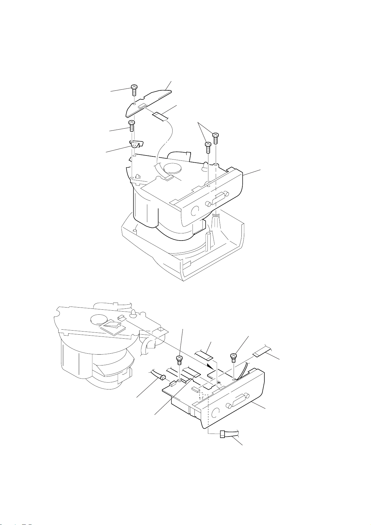
SECTION 2
DISASSEMBLY
Note : Follow the disassembly procedure in the numerical order given.
2-1. CAMERA CABINET (UPPER)
2
M 2x4
4
camera cabinet (front) assy
3
claw
5
6
camera cabinet (upper
1
M 2x4
PCS-C150/C150P
M 2x4
2-2. BOTTOM PLATE ASSY
5
buttom plate assy
1
M 2x4
3
PTP 2.6x8
4
M 2x4
2
M 2x
2-1
2-3. MAIN BLOCK
k
d
5
ground plate (P)
1
PTP 2.6x8
4
PTP 2.6x8
3
RM-77A(A) board
2
CN381
6
PTP 2.6x8
7
main bloc
2-4. ID-11A (A) BOARD
1
CN102
4
CN103
5
M 2x2.2
3
CN104
6
M 2x2.2
2
CN109
8
7
CN110
ID-11A (A) boar
2-2
)
Y
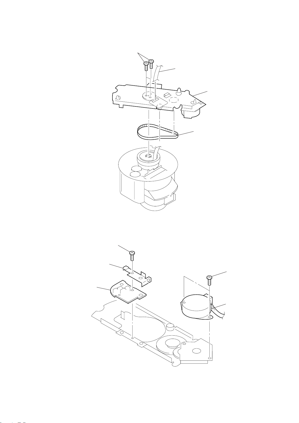
2-5. PAN BASE ASSY
1
P 2x6
3
flexible flat cable
2
timing belt
4
pan base ASS
2-6. LI-55A (A) BOARD
2
3
LI-55A(A) board
retainer
1
M 2x4
4
P 3x4
5
stepping motor (PAN
2-3
Y
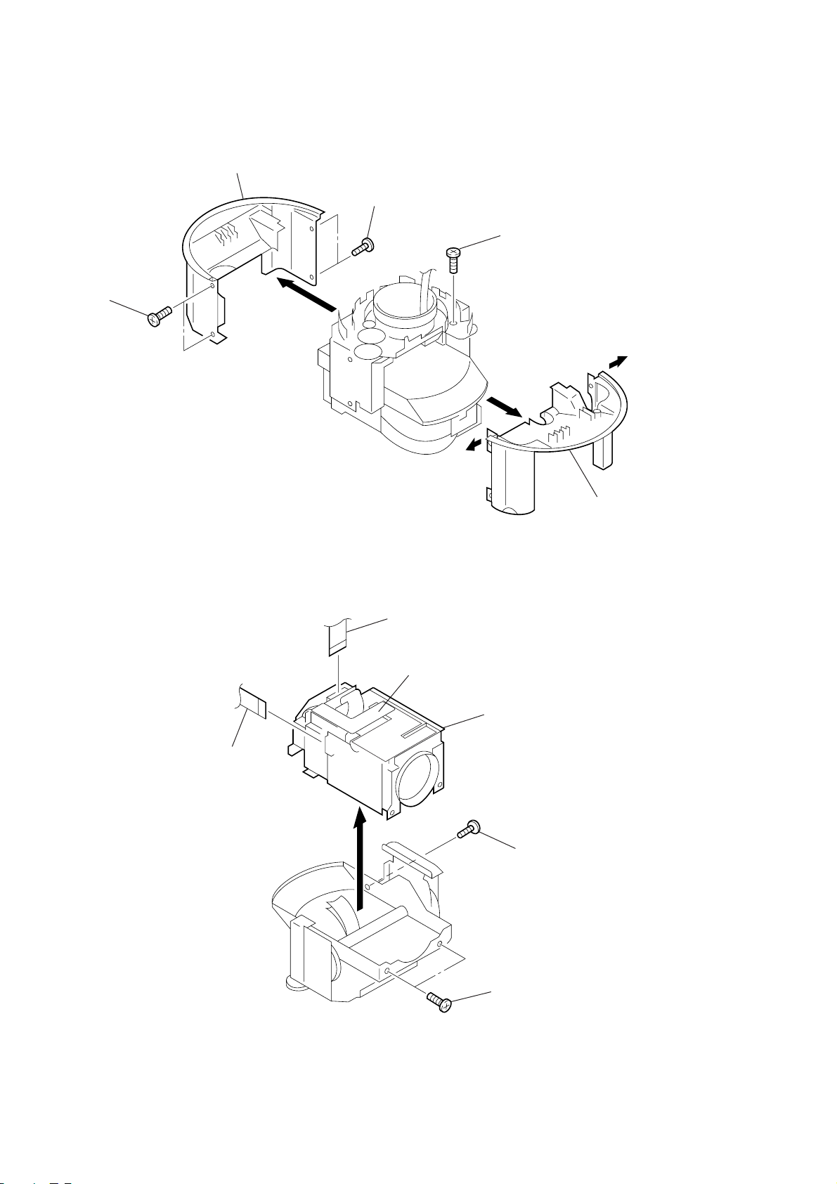
2-7. PAN CABINET
2
M 2x4
3
pan cabinet (front)
1
M 2x4
4
tapping screw
5
Extend the pan cabinet
(rear) out and remove
the cabinet.
2-8. CCD LENS ASSY
4
CN893
3
CN105
PCS-C150P only
5
CCD lens ASS
1
M 2x4
2-4
2
M 2x4
2
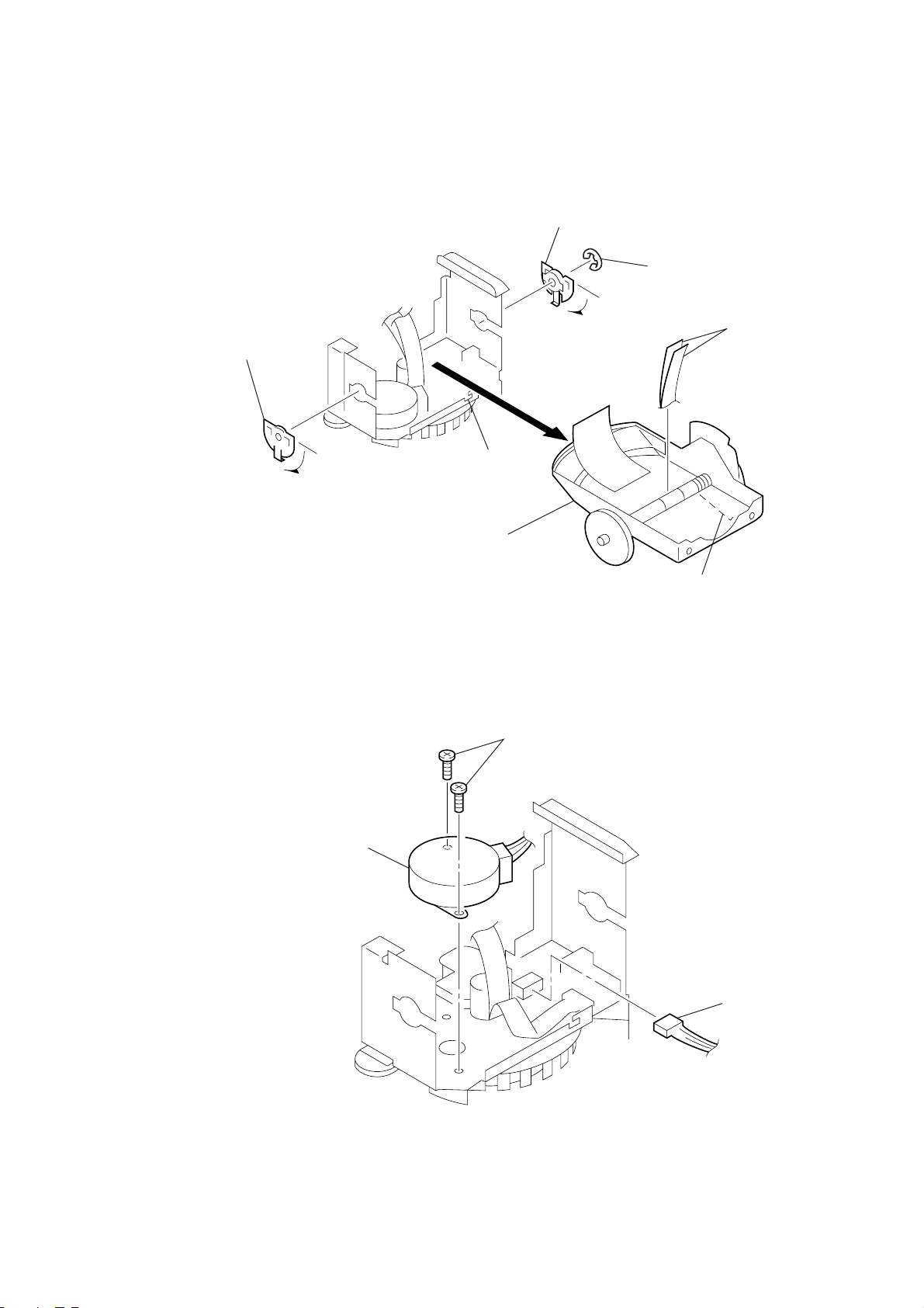
2-9. CAMERA CABINET (LOWER)
4
Turn the tilt bearing in the
direction of the arrow and
remove the bearing.
3
Turn the tilt bearing in the
direction of the arrow and
remove the bearing.
A
6
camera cabinet ASSY (lower)
2
type-E stop ring 3.0
5
flexible flat cable
2-10. STEPPING MOTOR
3
stepping motor (TILT)
2
P 3x4
1
Remove the spring from
portion A.
1
CN34
2-5
y
)
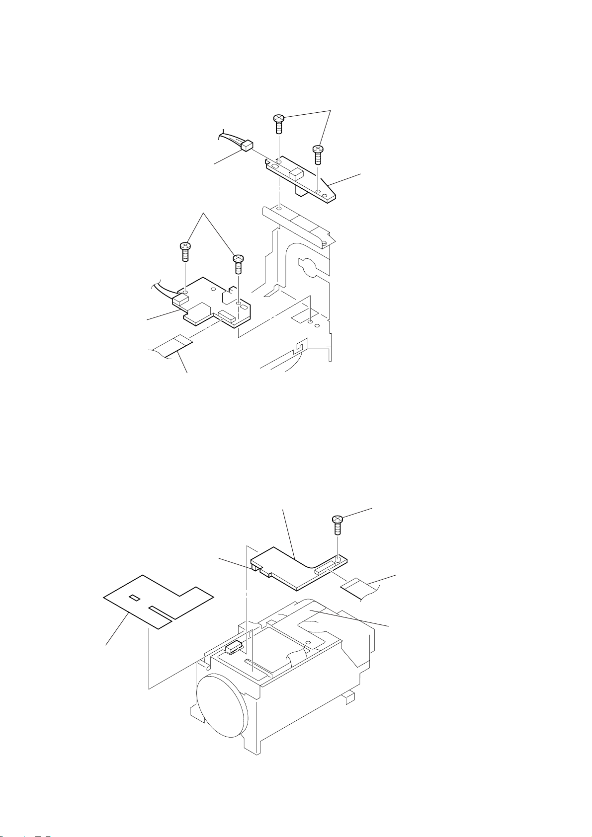
2-11. LI-59A (A) BOARD
6
LI-52A(A)
1
CN351
5
M 2x3
2
M 2x3
3
LI-59A(A
4
2-12. LD-84A (A)/84A (B) BOARD
2
CN702
4
Sheet,electrostatic
CN341
5
LD-84A(A)/84A(B) board
1
M 2x3
3
PCS-C150P onl
CN701
2-6
2-13. VC-179 (A)/179 (B) BOARD
6
M 2x3
5
M 2x3
3
8
CN894
CN504
7
CN401
9
VC-179(A)/179 (B) board
1
M 2x3
2-14. RS-67A (A)/LB-47A (A) BOARD
4
AT-21A(A) board
5
claw
1
claw
2
CN845
2
CN403
7
RS-67A(A) board
6
CN401
2-7
4
M 2x3
3
LB-47A(A) board
3
)
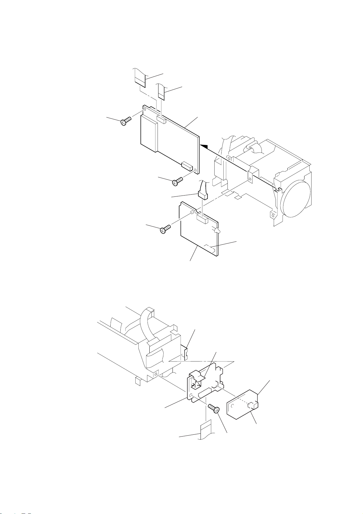
2-15. MD-68 (A) BOARD 2-17. CD-154A (A) BOARD
3
MD-68 (A) board
1
BTP 2x12
2
M 2x
1
M 2x3
2
CD-154A(A) board
2-16. LENS BLOCK
1
BTP 2x5
2
lens block
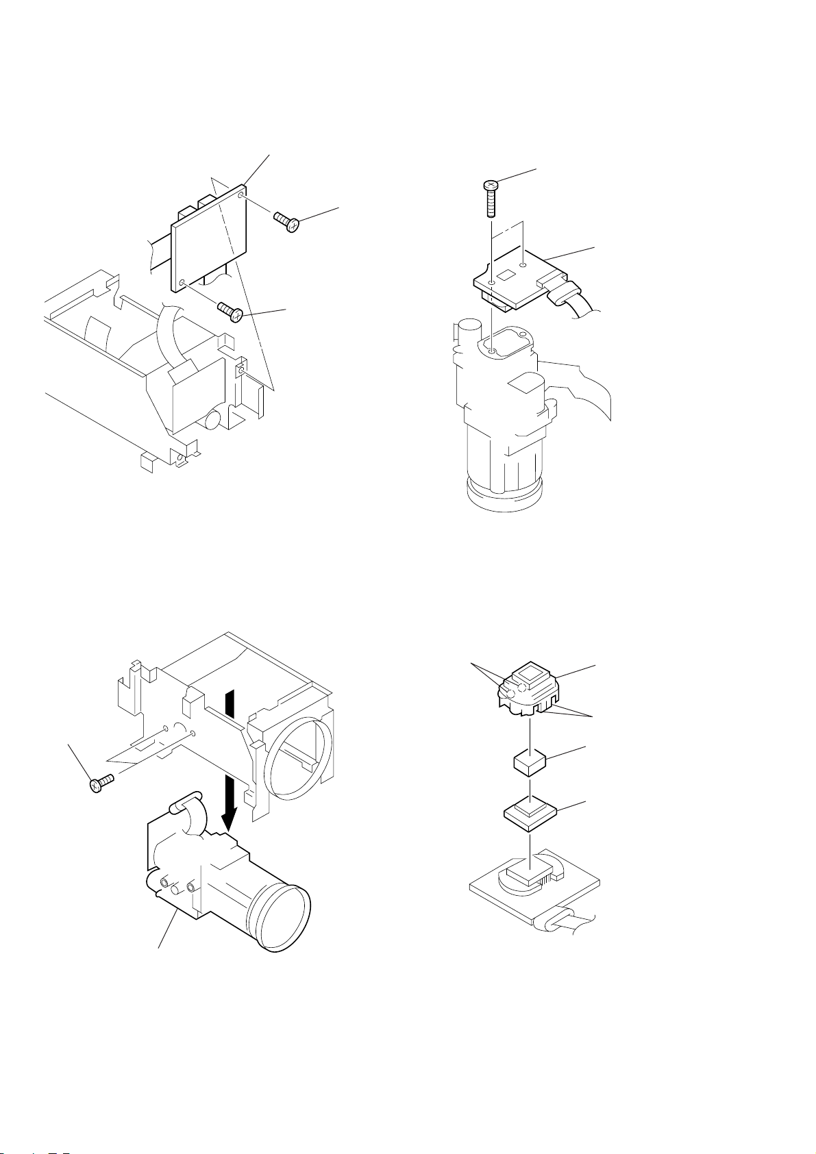
2-18. CCD FITTING ADAPTOR (H)
1
claw
3
CCD fitting adaptor (H
2
claw
4
optical filter block
5
seal rubber (3)
2-8
2-8E
d
d
PRINTED WIRING BOARDS
5-1. CIRCUIT BOARDS LOCATION
ID-11A(A) board
PCS-C150/C150P
SECTION 5
LI-59 A(A) board
RM-77A(A) board
AT-21A(A) board
LI-52A(A) boar
LI-55A(A) board
LB-47A(A) board
RS-67A(A) boar
MD-68 (A) board
VC-179 (A)/179 (B) board
CD-154A(A) board
LD-84A(A)/84A(B) board
5-1
PCS-C150/C150P
5-2. PRINTED WIRING BOARDS
THIS NOTE IS COMMON FOR PRINTED WIRING BOARDS.
For printed wiring boards.
•
• Through hole is omitted.
• Pattern is omitted.
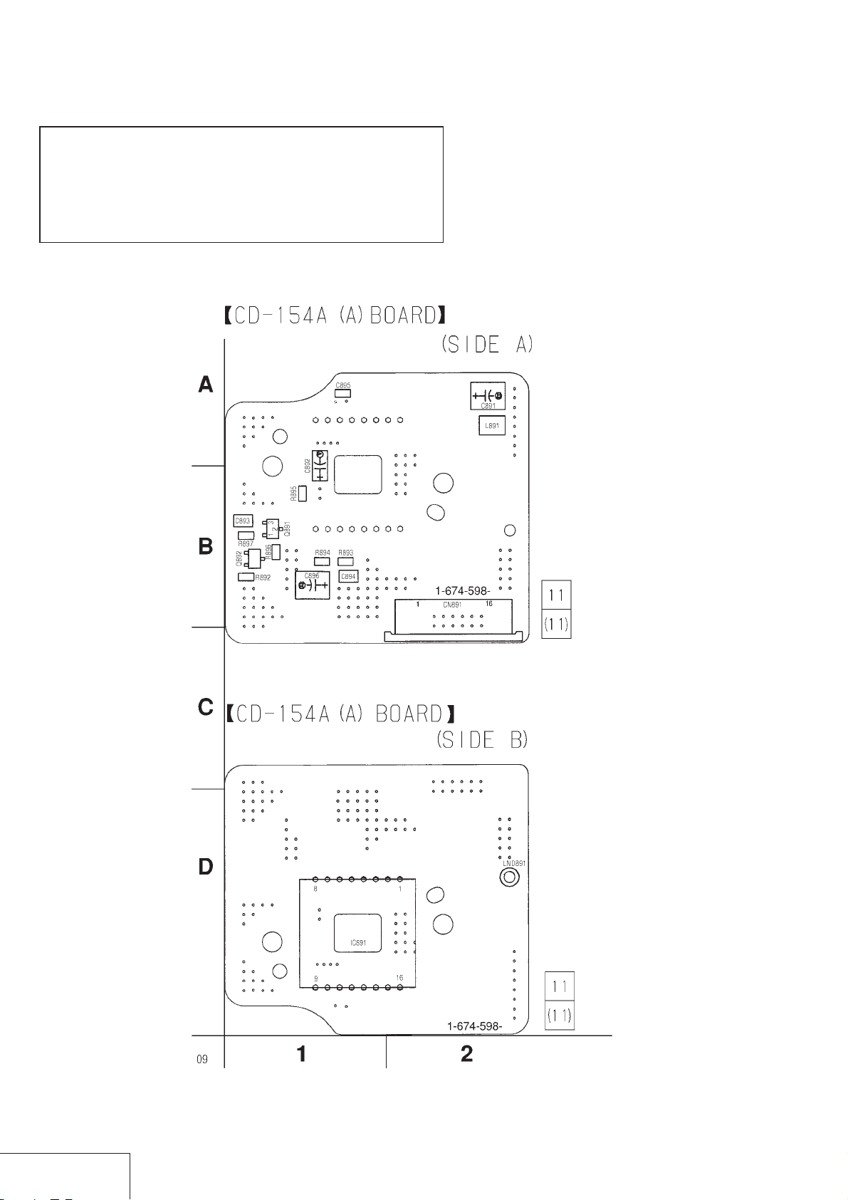
CD-154A (A) (CCD IMAGER) PRINTED WIRING BOARD
– Ref. No. CD-154A (A) BOARD : 1,000 series –
CD-154A (A)
BOARD
IC891 D-1
Q891 B-1
Q892 B-1
CCD IMAGER
CD-154A (A)
5-2
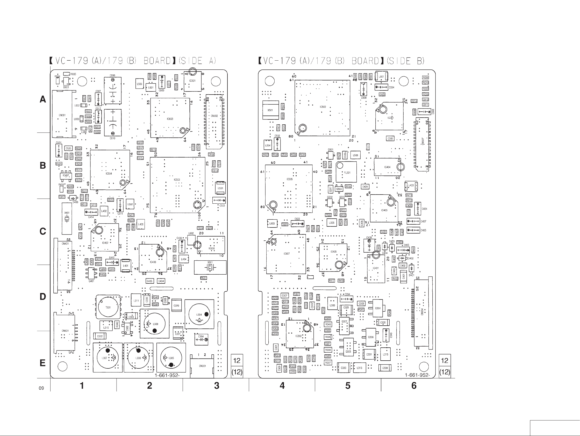
VC-179 (A)/179 (B) (CAMERA) PRINTED WIRING BOARD
– Ref. No. VC-179 (A)/179 (B) BOARD : 1,000 series –
VC-179 (A)/179 (B)
BOARD
D001 A-1
D302 D-2
D401 D-6
D402 C-6
D403 C-6
D404 C-6
D406 B-1
IC001 A-6
IC302 E-4
IC401 D-5
IC402 C-1
IC403 C-6
IC404 B-6
IC405 C-5
IC406 C-2
IC407 B-1
IC501 A-3
IC502 A-5
IC503 B-2
IC504 B-1
IC505 B-4
IC603 A-2
IC606 C-3
IC607 C-4
Q304 D-5
Q305 E-5
Q306 E-5
Q307 D-5
Q308 D-2
Q401 D-1
Q502 C-5
Q503 C-5
Q504 B-5
Q601 B-5
PCS-C150/C150P
5-3
5-4
CAMERA
VC-179 (A)/179 (B)
PCS-C150/C150P
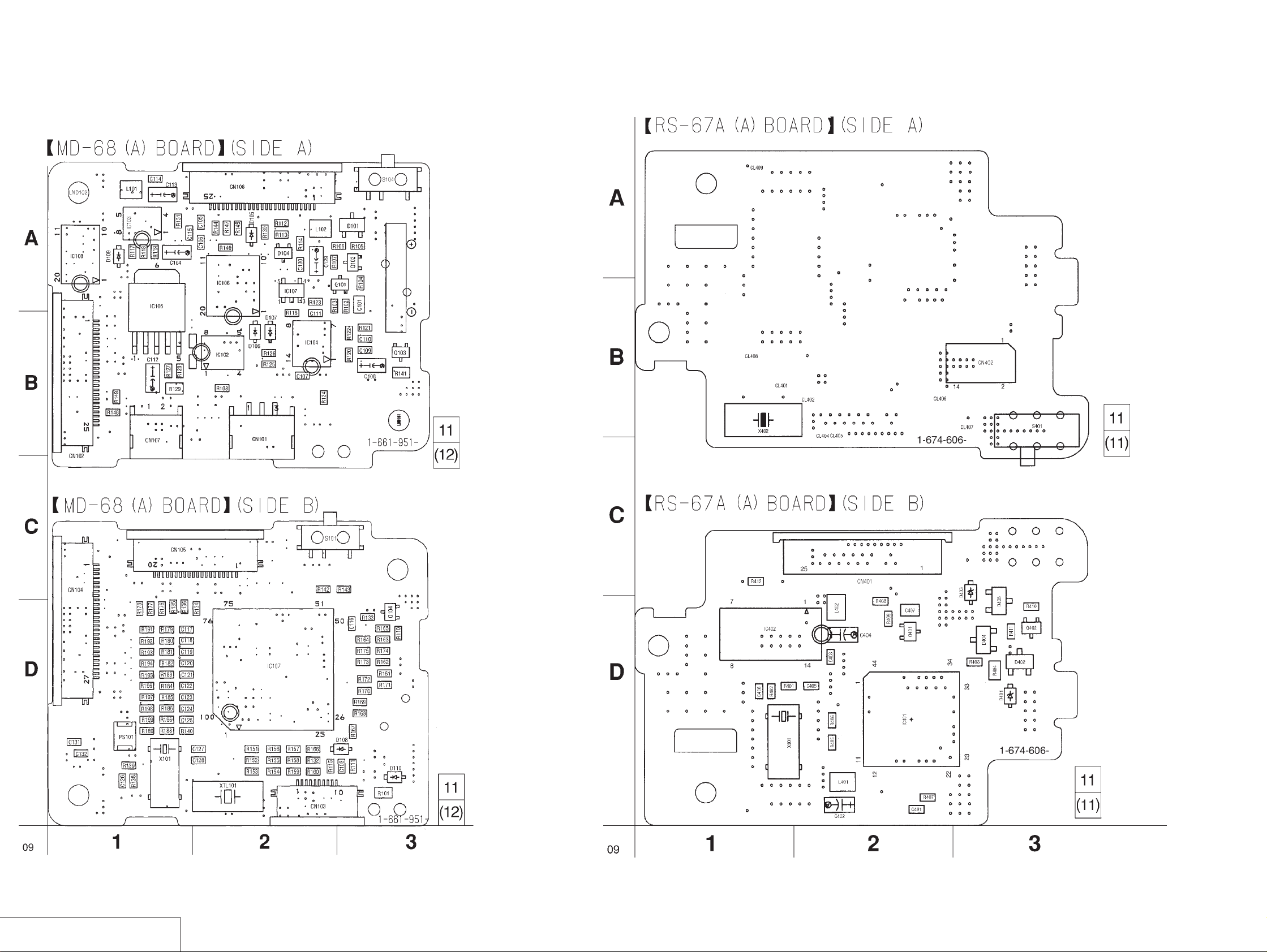
MD-68 (A) (MODE CONTROL) RS-67A (A) (BACK UP) PRINTED WIRING BOARDS
– Ref. MD-68 (A) BOARD : 1,000 series, RS-67A (A) BOARD : 2,000 series –
MD-68 (A)
BOARD
D101 A-3
D104 A-2
D105 A-2
D106 B-2
D107 B-2
D108 D-3
D109 A-1
D110 D-3
IC101 D-2
IC102 B-2
IC103 A-1
IC104 B-2
IC105 A-1
IC106 A-2
IC107 A-2
IC108 A-1
Q101 A-2
Q102 A-3
Q103 B-3
Q104 D-3
RS-67A (A)
BOARD
D401 D-3
D402 D-3
D403 C-3
D404 D-3
D405 D-3
IC401 D-2
IC402 D-3
Q401 D-2
Q402 D-3
MODE CONTROL, BACK UP
MD-68 (A), RS-67A (A)
5-5
5-6
PCS-C150/C150P
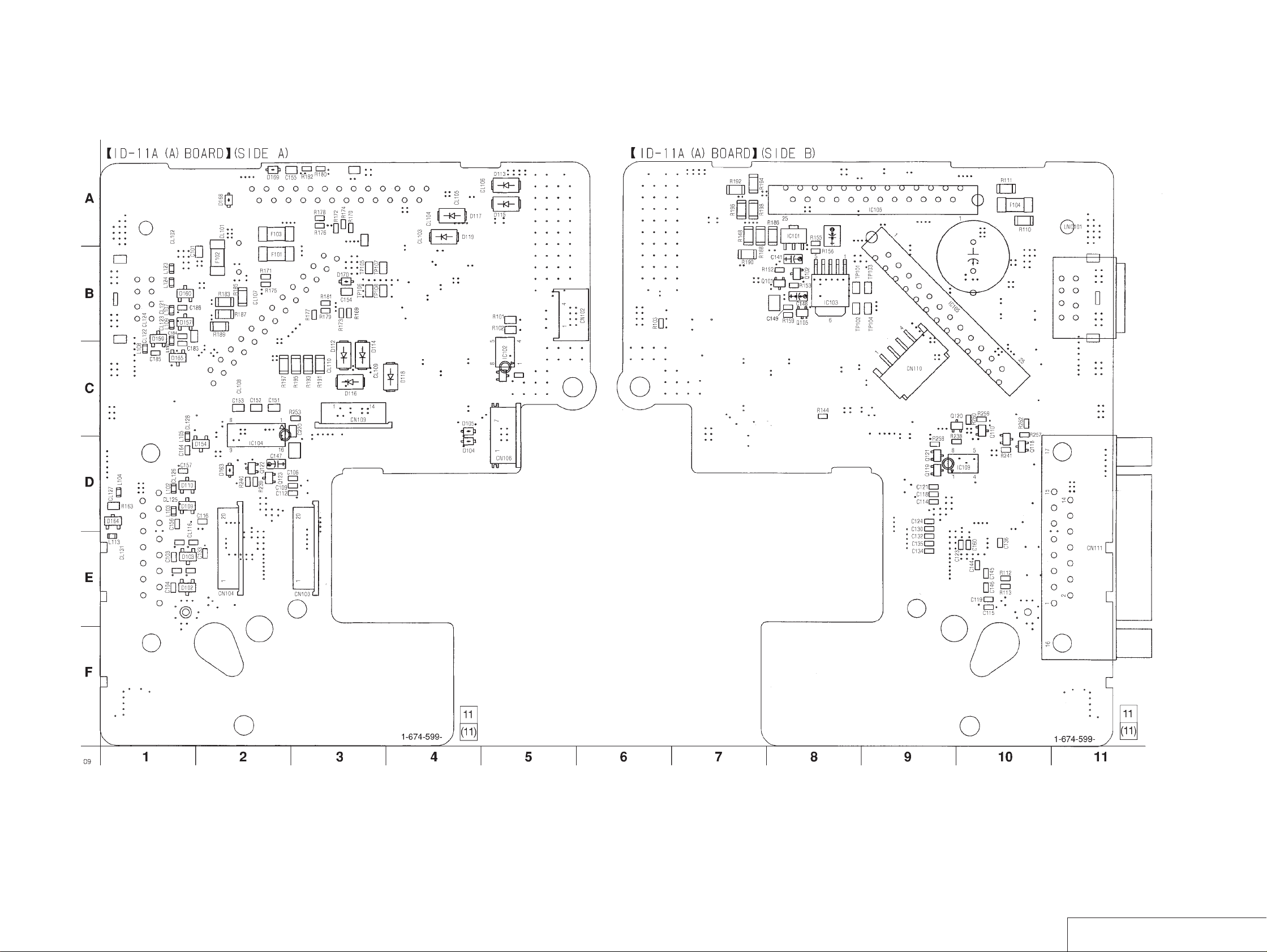
ID-11A (A) (MOTOR DRIVE, INPUT/OUTPUT) PRINTED WIRING BOARDS
– Ref. No. ID-11A (A) BOARD : 2,000 series
ID-11A (A)/11A (A)
BOARD
D102 E-1
D103 E-1
D104 D-4
D105 C-4
D109 D-1
D110 D-1
D112 C-3
D113 A-5
D114 C-3
D115 A-5
D116 C-3
D117 A-4
D118 C-4
D119 A-4
D154 D-2
D157 B-1
D159 B-1
D160 B-1
D163 D-2
D164 D-1
D165 C-1
D168 A-2
D169 A-2
D170 B-3
IC101 A-8
IC102 C-5
IC103 B-8
IC104 C-2
IC105 B-9
IC106 A-9
IC109 D-9
Q101 B-8
Q102 B-8
Q105 B-8
Q110 C-10
Q118 D-10
Q119 D-9
Q120 C-9
Q121 D-9
Q122 D-2
Q123 D-2
5-7
5-8
MOTOR DRIVE, INPUT/OUTPUT
ID-11A (A)

PCS-C150/C150P
AT-21A (A) (VIDEO PROCESS, MAIN CONTROL) LI-52A (A) (TILT END SENSOR) LI-59A (A) (TILT R SENSOR) LI-55A (A) (PAN R SENSOR) PRINTED WIRING BOARDS
– Ref. No. AT-21A (A) BOARD : 1,000 series, LI-52A (A) BOARD : 2,000 series, LI-55A (A) BOARD : 2,000 series, LI-59A (A) BOARD : 2,000 series –
AT-21A (A)
BOARD
D801 C-1
D802 B-3
D803 A-2
D804 A-1
D805 A-1
D806 A-3
D807 B-3
D808 B-1
D809 A-1
IC801 E-2
IC802 B-2
IC803 D-2
IC804 E-4
Q801 D-2
Q802 E-3
Q803 D-3
VIDEO PROCESS, MAIN CONTROL, SENSOR
AT-21A (A), LI-52A (A), LI-55A (A), LI-59A (A)
5-9
5-10
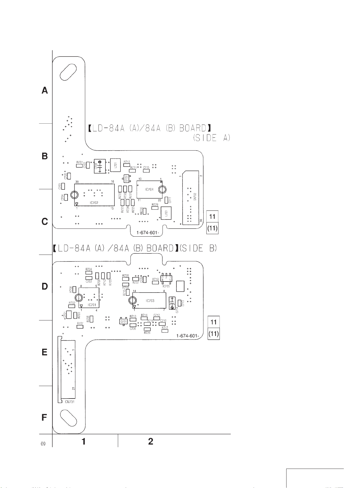
LD-84A (A)/84A (B) (LENS DRIVE) PRINTED WIRING BOARD
– Ref. No. LD-84A (A)/84A (B) BOARD : 2,000 series –
LD-84 A (A)/84A (B)
BOARD
IC701 D-1
IC702 C-1
IC703 D-2
IC704 C-2
IC705 D-2
Q701 E-2
Q702 B-2
PCS-C150/C150P
5-11
LENS DRIVE
LD-84A (A)/84A (B)
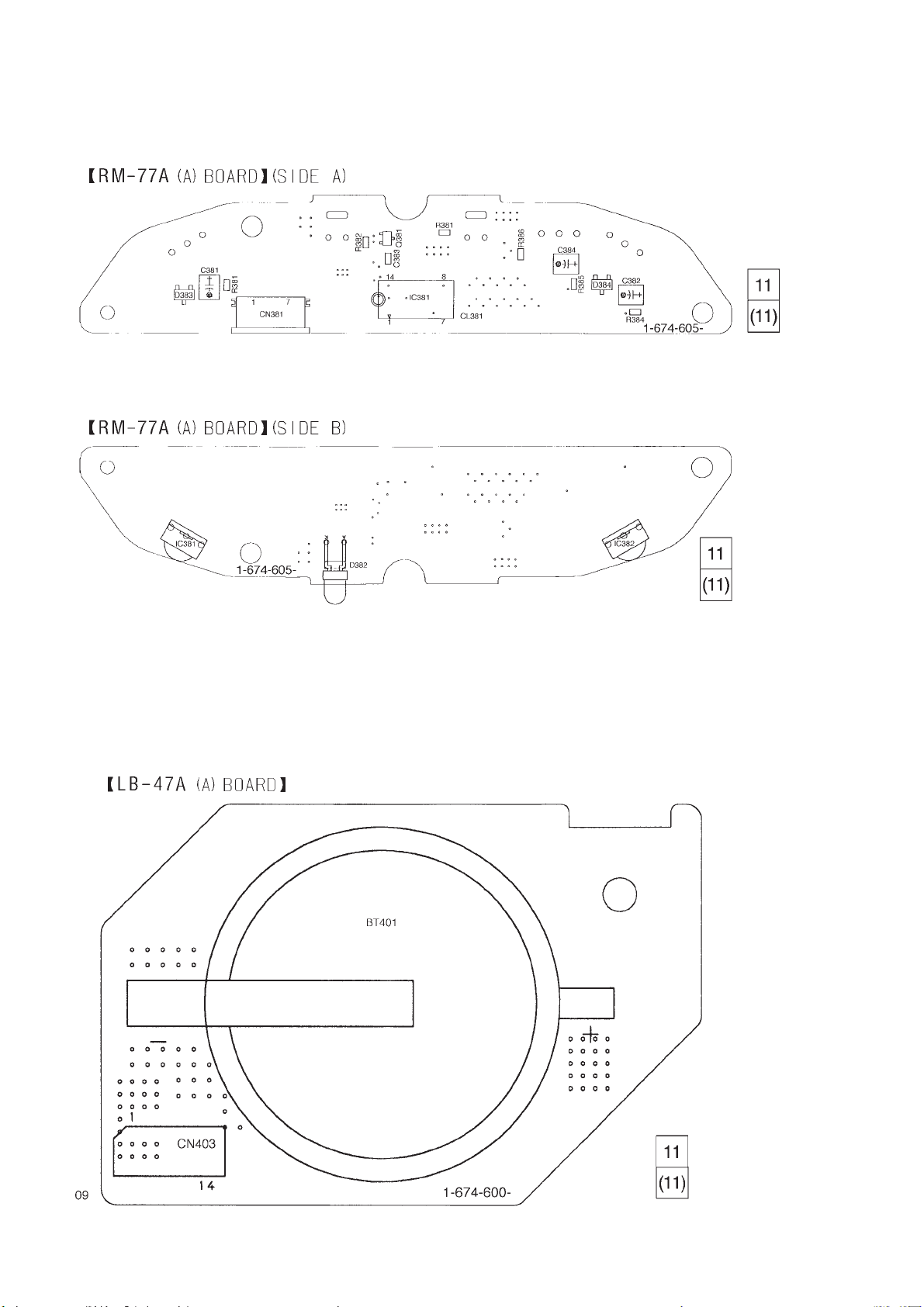
RM-77A (A) (REMOCON RECEIVING OPTICAL), LB-47A (A) (B ATTER Y) PRINTED WIRING BO ARD
– Ref. No. RM-77A BOARD : 1,000 series, LB-47A (A) BOARD : 1,000 series –
5-12
E
SECTION 6
PCS-C150/C150P
ADJUSTMENTS
6-1. PREPARATION FOR ADJUSTMENT
6-1-1. List of Servicing Jigs
• Oscilloscope • Regulated power supply • Audio generator • Audio level meter
• Color monitor • Vectorscope • Desk-top calculator • Digital voltmeter
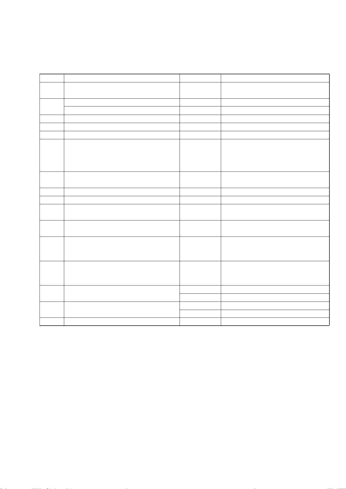
Ref. No. Name Part No. Use
J-1 Filter for color temperature correction J-6080-058-A Auto white balance adjustment/check
(C14) White balance adjustment/check
J-2 ND filter 1.0 J-6080-808-A White balance check
ND filter 0.3 J-6080-818-A White balance check
J-3 Pattern box PTB-450 J-6082-200-A
J-4 Color chart for pattern box J-6020-250-A
J-5 Siemens star J-6080-875-A For checking the flange back
J-6 Extension cable (30P, 0.8mm) J-6082-189-A For extension between LD-84A (A)/84A (B) board
(CN702) and VC-179 (A)/179 (B) board (CN501),
AT-21A (A) board (CN845) and
VC-179 (A)/179 (B) board (CN502).
J-7 Adjusting remote commander (*1) J-6082-053-B
(RM-95 remodeled partly)
J-8 Extension cable 3 J-6082-291-A For adjusting remote commander (J-7)
J-9 Video/S video out cable J-6082-293-A For checking the video signal
J-10 DC-57 harness (2P) 1-951-473-11 For DC-supply to VC-179 (A)/179 (B) board
(CN301)
J-11 RS-232C cable (8P DIN-8P DIN) 1-590-879-11 For connection between processor terminal
and Macintosh PC
J-12 RS-232C cable (8P DIN-25P DSUB) 1-751-195-11 For connection between processor terminal
SMF-532A and NEC PC98
(79-6363-00)
J-13 RS-232C cable (8P DIN-9P DSUB female) 1-690-391-21 For connection between processor terminal
SMF-533 and IBM PC, Quarter-L
(48-5233-00)
J-14 VISCA Control Software J-6082-297-A For IBM PC/NEC PC98
J-6082-296-A For Macintosh PC
AC Adaptor 1-473-789-11 AC-EV2 (AC120V)
(Output voltage: 13.5Vdc) 1-473-790-11 AC-EV3 (AC220-230V)
J-15 Input/Output conversion board J-2500-222-1 D SUB Video/VISCA Conversion (*2)
*1 Microcomputer IC in the adjusting remote commander except for µPD7503G-C56-12 (8-759-148-35) does not allow the page select-
ing. Replace the microcomputer in such a case.
*2 Remove the hexagonal screws of the D-SUB on the board before using the tool board.
6-1

J-1
J-2
J-3
J-4
J-5
J-6
J-11
J-7
J-12
J-8
J-13
6-1-2. Preparations
Note: When adjusting only, it is not needed to remove the camera
block from the pan tilt mechanism chassis.
The adjustments can be performed only by removing the
camera cabinet.
1) Connect the equipments for adjusting as shown in Fig. 6-3.
2) Turning OFF the auto focus using the adjusting remote
commander.
1. Set data: 01 to page: 6, address: 25.
(The auto focus will turn OFF. The focus can be adjusted
using the focus button on the adjusting remote commander.
But the HOLD switch must be set to OFF.)
2. After completing the adjustment/operation check, set data:
00 to page: 6, address: 25.
3) To adjust the camera block only, there are two procedures.
1. Adjust with the camera block mounted to the pan tilt
mechanism chassis. (Fig. 6-2 (1), Fig. 6-3 (1))
Note: AT-21A (A) board must be removed before 28MHz
original oscillation adjustment can be performed.
2. Remove the camera block from the pan tilt mechanism
chassis and perform adjustment to the camera block only.
(Fig. 6-2 (2), Fig. 6-3 (2))
Note: Be sure to change the data of page: D, address: 01 to 00
(NTSC) or 01 (PAL). Then, remove the camera block
from the pan tilt mechanism chassis.
After this adjustment, be sure to perform the operation
described in 6-2-20 and 6-2-22.
Fig. 6-1.
J-9
J-14
J-10
J-15
1.5m
Front of the
lens
Fig. 6-2 (1) .
Fix the
block on table.
Fig. 6-2 (2) .
Note: The camera block has no screw plate for tripod. So, fix the
block on a table when adjusting.
6-2

VC-179(A)/179(B) board
LD-84A(A)/84A(B) board
CN101
Extension cable
(J-6082-189-A)
CN502
CN845
AT-21A(A) board
Personal computer
IBM PC/NEC PC98/
Macintosh
AC adaptor
AC-EV2 (D30)
AC-EV3 (D31)
MD-68(A) board
RS-67A(A) board
Adjusting remote commander
(J-6082-053-B)
VISCA
IN
Extension cable 3
for adjusting
remote commander
(J-6082-291-A)
Fig. 6-3 (1).
S VIDEO
OUT
J-2500-222-1
Input/output
conversion board
DC IN 13.5V
Vectorscope Color monitor
RS-232C cable
1-590-879-11 (Macintosh)
1-690-391-21 (IBM PC)
1-751-195-11 (NEC PC98)
6-3

d
Color monitor Vectorscope
)
Ω
(Terminated at 75
AT-21A (A) boar
CN845
0.1Vdc)
Extension cable
(J-6082-189-A)
CN001
CN502
±
Regulated power supply
(6.3
Adjusting remote commander
(J-6082-053-B)
CN702
LD-84A (A)/84A (B) board
Extension cable
Extension cable 3
for adjusting
remote commander
(J-6082-291-A)
CN501
(J-6082-189-A)
VC-179 (A)/179 (B) board
CN101
CN301
CN105
DC-57 harness
(1-951-473-11)
MD-68 (A) board
Fig. 6-3 (2).
6-4
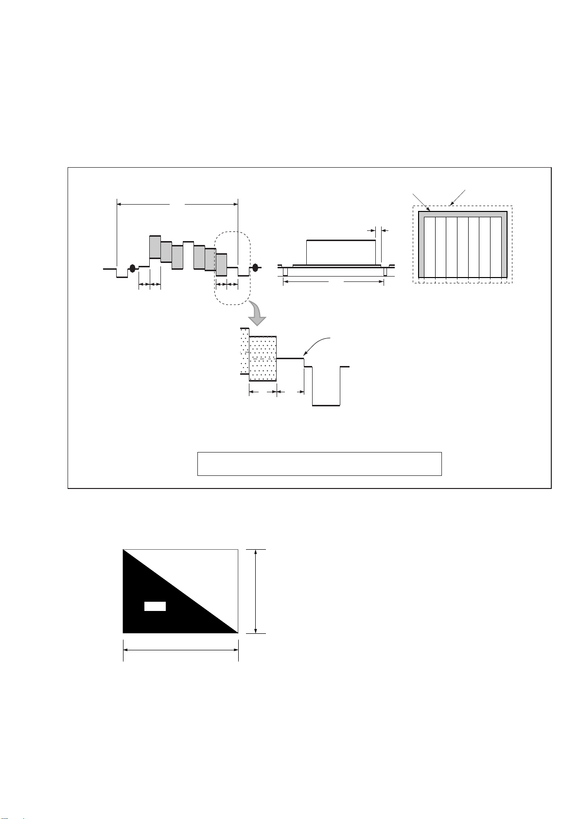
Fig. b. (TV monitor picture)
Fig. a. (Video output terminal
output waveform)
CRT picture frame
0 ± 0.1 msec
V
Difference in level
Enlargement
AB
ABABHA = B
Color bar chart standard picture frame
Yellow
Cyan
Green
White
Magenta
Red
Blue
Yellow
Cyan
Green
White
Magenta
Red
Blue
Electoronic beam
scanning frame
6-1-3. Precautions
1. Adjusting Procedure
Adjust in the given order.
2. Subject
1) Color bar chart (Standard picture frame)
Adjust the picture frame as shown in Fig. 6-4. if adjustments
are performed using the color bar chart. (Standard picture frame)
2) White pattern (Standard picture frame)
Remove the color bar chart from the pattern box, and so that
the white pattern will be displayed.
Don’t touch the zoom switch.
3) Chart for flange back adjustment
Combine a white A0 size (1189 mm × 841 mm) paper to a
black one, and make the chart shown in Fig. 6-5.
Note: Use the non-reflecting and non-glazing vellum paper whose
size is more than A0, and make the boundary between white
and black to be smoothly flat.
Black
Fig. 6-5.
Adjust the camera zoom and direction to obtain the output waveform
shown in Fig. a and the TV monitor display shown in Fig. b.
White
1189mm
Fig. 6-4.
841mm
6-5
 Loading...