

Sony PCG-SR27, PCG-SR27K Service Manual
PCG-SR27/SR27K
Includes PCG-SR33/SR33K Difference Manuals
SERVICE MANUAL
Illust : PCG-SR27K
US Model
Canadian Model
S400
Confidential
9-872-215-11
NOTEBOOK COMPUTER

Information in this document is subject to change without notice.
Sony and VAIO are trademarks of Sony. Intel logo and Intel Inside
logo are registered trademarks of Intel Corporation. Pentium MMX
is a trademark of Intel Corporation. Microsoft, MS-DOS, Windows,
the Windows 95 and Windows 98 logo are trademarks of Microsoft
Corporation.
All other trademarks are trademarks or registered trademarks of
their respective owners. Other trademarks and trade names may be
used in this document to refer to the entitles claiming the marks and
names or their produces. Sony Corporation disclaims any proprietary
interest in trademarks and trade names other than its own.
Caution Markings for Lithium/Ion Battery - The following or similar
texts shall be provided on battery pack of equipment or in both the
operating and the service instructions.
CAUTION: Danger of explosion if battery is incorrectly replaced.
Replace only with the same or equivalent type recommended by
the manufacturer. Discard used batteries according to the
manufacturer’s instructions.
CAUTION: The battery pack used in this device may present a fire
or chemical burn hazard if mistreated. Do not disassemble, heat
above 100°C (212°F) or incinerate.
Dispose of used battery promptly.
Keep away from children.
CAUTION: Changing the back up battery.
• Overcharging, short circuiting, reverse charging, multilation or
incineration of the cells must be avoided to prevent one or more of
the following occurrences; release of toxic materials, release of
hydrogen and/or oxygen gas, rise in surface temperature.
• If a cell has leaked or vented, it should be replaced immediately
while avoiding to touch it without any protection.
Service and Inspection Precautions
1. Obey precautionary markings and instructions
Labels and stamps on the cabinet, chassis, and components identify areas
requiring special precautions. Be sure to observe these precautions, as well
as all precautions listed in the operating manual and other associated
documents.
2. Use designated parts only
The set’s components possess important safety characteristics, such as
noncombustibility and the ability to tolerate large voltages. Be sure that
replacement parts possess the same safety characteristics as the originals.
Also remember that the 0 mark, which appears in circuit diagrams and
parts lists, denotes components that have particularly important safety
functions; be extra sure to use only the designated components.
3. Always follow the original design when mounting
parts and routing wires
The original layout includes various safety features, such as inclusion of
insulating materials (tubes and tape) and the mounting of parts above the
printer board. In addition, internal wiring has been routed and clamped so
as to keep it away from hot or high-voltage parts. When mounting parts or
routing wires, therefore, be sure to duplicate the original layout.
4. Inspect after completing service
After servicing, inspect to make sure that all screws, components, and wiring
have been returned to their original condition. Also check the area around
the repair location to ensure that repair work has caused no damage, and
confirm safety.
5. When replacing chip components...
Never reuse components. Also remember that the negative side of tantalum
capacitors is easily damaged by heat.
6. When handling flexible print boards...
• The temperature of the soldering-iron tip should be about 270C.
• Do not apply the tip more than three times to the same pattern.
• Handle patterns with care; never apply force.
Caution: Remember that hard disk drives are easily damaged by
vibration. Always handle with care.
ATTENTION AU COMPOSANT AYANT RAPPORT
À LA SÉCURITÉ!
LES COMPOSANTS IDENTIFÉS PAR UNE MARQUE 0 SUR LES
DIAGRAMMES SCHÉMATIQUES ET LA LISTE DES PIÈCES SONT
CRITIQUES POUR LA SÉCURITÉ DE FONCTIONNEMENT. NE
REMPLACER CES COMPOSANTS QUE PAR DES PIÈSES SONY
DONT LES NUMÉROS SONT DONNÉS DANS CE MANUEL OU
DANS LES SUPPÉMENTS PUBLIÉS PAR SONY.
Confidential
PCG-SR27/SR27K (UC)
— 2 —

TABLE OF CONTENTS
Section Title Page
CHAPTER 1. REMOVAL
1-1. Flowchart ......................................................................... 1-1
1-2. Main Electrical Parts Location Diagram ......................... 1-1
1-3. Removal ........................................................................... 1-2
1. Keyboard Unit, Parm Assy .............................................. 1-2
2. Touch pad, Speaker (R), SWX-61 Board ........................ 1-2
3. HDD ................................................................................. 1-3
4. Speaker (L), IFX-125 Board ............................................ 1-3
5. Frame Assy, DC Fan, Cooling ......................................... 1-4
6. Main Board Assy ............................................................. 1-4
7. MBX-44 Board, IFX-124 Board, DDC-3 Board
V/L Rechargeable Battery ............................................... 1-5
8. CNX-107 Board ............................................................... 1-5
9. Display Assy .................................................................... 1-6
10. LCD Section – Made by TS –......................................... 1-6
1.Housing (Bezel) Assy ................................................... 1-6
2.Microphone, LCD Assy, Inverter Unit,
ANL-24 Board .............................................................. 1-7
(to 1-7)
CHAPTER 2. SELF DIAGNOSTICS
(to 2-1)
CHAPTER 3. BLOCK DIAGRAM ............................... 3-1
(to 3-2)
CHAPTER 4. FRAME HARNESS DIAGRAM ........ 4-1
(to 4-2)
CHAPTER 5. EXPLODED VIEWS AND
PARTS LIST
5-1. Main Section .................................................................... 5-1
5-2. LCD Section – Made by TS –.......................................... 5-5
(to 5-6)
• Abbreviations
UC : US model / Canadian model
— 3 —
Confidential
PCG-SR27/SR27K (UC)
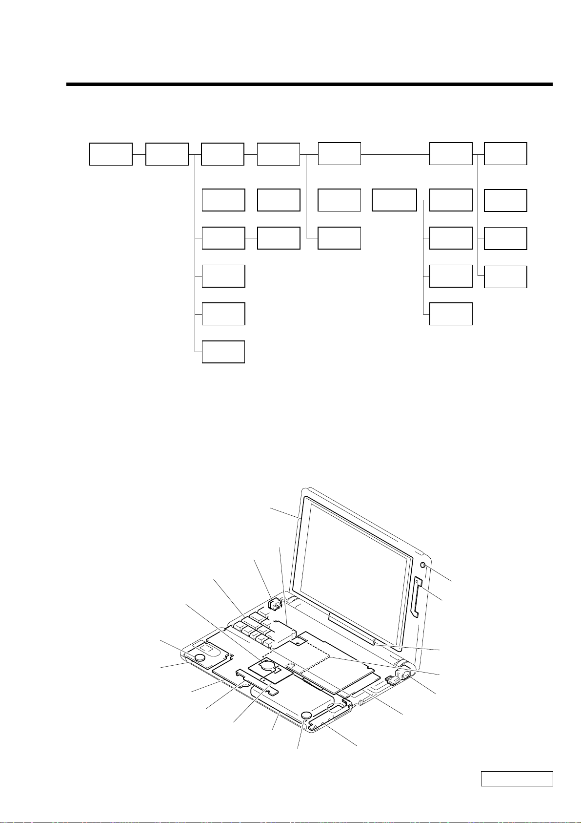
1-1. Flowchart
CHAPTER 1.
REMOVAL
POWER
OFF
PARM ASSY
P1-2
KEYBOARD
UNIT
P1-2
HDD
IFX-125
BOARD
P1-3
SWX-61
BOARD
P1-2
TOUCH PAD
P1-2
SPEAKER (R)
P1-2
FRAME
ASSY
P1-4
CNX-107
BOARD
P1-5P1-3
SPEAKER (L)
P1-3
DISPLAY
ASSY
P1-6
DC FAN
P1-4
COOLING
P1-4
MAIN BOARD
ASSY
P1-4
• P XX means pages that appears in this manual.
• Remember that hard disk drives are easily damaged by vibration. Always handle with care.
HOUSING
(BEZEL)
ASSY
P1-7
MBX-44
BOARD
P1-5
IFX-124
BOARD
P1-5
DDC-3
BOARD
P1-5
V/L
RECHARGEABLE
BATTERY
P1-5
MICRO
PHONE
P1-7
LCD
ASSY
P1-7
INVERTER
UNIT
P1-7
ANL-24
BOARD
P1-7
1-2. Main Electrical Parts Location Diagram
LCD Assy
DC Fan
DC Jack
Keyboard Unit
V/L Rechargeable Battery
Speaker
IFX-125 Board
MBX-44 Board
SWX-61 Board
Touch pad
HDD
Speaker
CNX-107 Board
IFX-124 Board
Microphone
ANL-24 Board
Inverter Unit
DDC-3 Board
Modular Jack
Confidential
1-1 PCG-SR27/SR27K (UC)
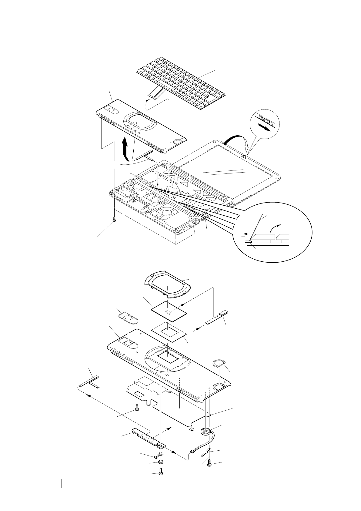
1-3. Removal
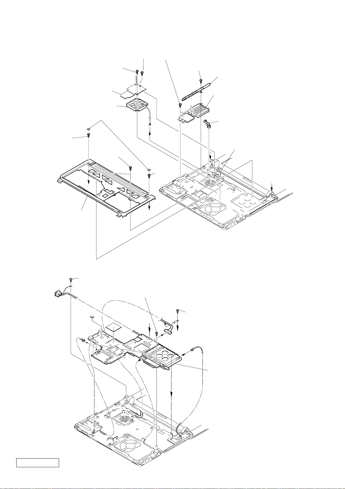
1. Keyboard Unit, Parm Assy
8 Housing (Parm Rest) Assy
0 Keyboard Unit
9
4
6
7 FFC
(MBX-34-SWX-55)
Claw
1 Lock Ace (M2X6) (X7) (Silver)
2. Touch pad, Speaker (R), SWX-61 Board
qf Touch Pad
Window MS
5
3
Claw
qd Escutcheon (Pad)
qa
2
A
Latch (Key)
Clip or the
like
B
ql Housing (Parm Rest) Assy
7 FFC (MBX-34-SWX-55)
6
4 Tapping Screw
(M2X4) (Black)
q; SWX-61 Board
3 Ground plate (SWX)
2 Bushing (PC Board)
1 Tapping Screw
Confidential
(M2X4) (Black)
a
1-2PCG-SR27/SR27K (UC)
a
qs FFC (SWX-55-Touch Pad)
qg Sheet (Touch Pad) (2)
Jog Window
5 Shield (Parm)
qk Speaker
9
qj Speaker Holder
8
qh Tapping Screw
(M2X4) (X2) (Black)
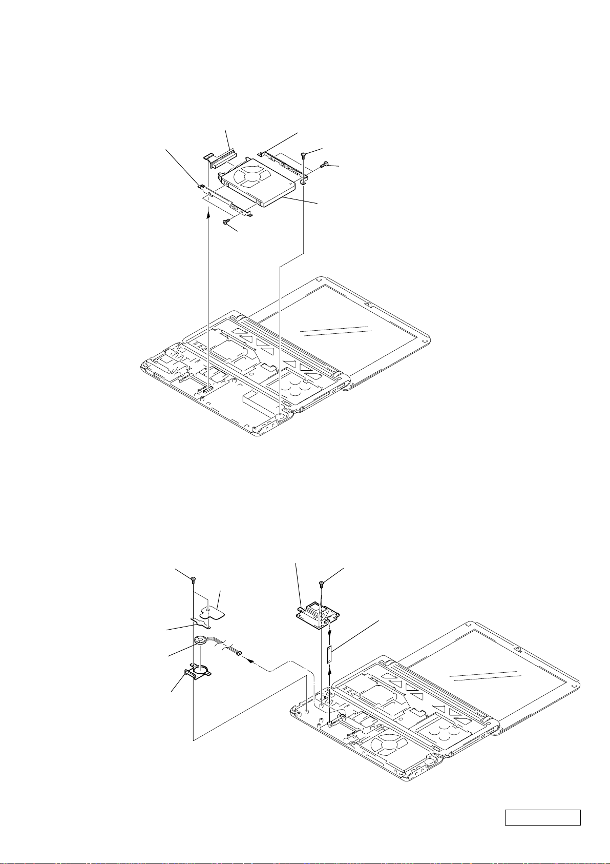
3. HDD
7 FPC (HDD)
4 Bracket (B)
6 Bracket (F)
1 Lock Ace (M2X3.5) (Gold)
3 Screw (M3X4) (X2) (Gold)
2
5 Screw (M3X4)
(X2) (Gold)
4. Speaker (L), IFX-125 Board
8 HDD
7 Lock Ace (M2X3.5) (X2) (Gold)
9 Speaker Holder
q; Speaker
qa Duct (L)
5 IFX-125
8 Shield MS
6
Board
1 Lock Ace (M2X3.5) (X2) (Gold)
4 FFC (MBX-34-IFX-109)
3
2
Confidential
1-3 PCG-SR27/SR27K (UC)
5. Frame Assy, DC Fan, Cooling
7 Lock Ace (M2X3.5) (Gold)
6 +BTP 2X6 (X2) (Black)
8 Heatsink NT2
q; DC Fan
1 Blind, Screw (X2)
2 Lock Ace
(M2X6) (Silver)
a
5 Frame Assy
3 +B 2X6
(X2)
qd Lock Ace (M2X3.5) (X4) (Gold)
qa Lock Ace (M2X3.5) (Gold)
qs Escutcheon (LB)
qf Cooling (1)
qg Bushing (FAN)
9
4 Claw
a
2 +B 2X6
(Gold)
b
b
6. Main Board Assy
5 Lock Ace (M2.6X4) (Silver)
q; Lock Ace (M2X3.5) (X2) (Gold)
a
2
3
4
9 Lock Ace (M2X3.5) (Gold)
a
8
7
qa Main Board Assy
6
Confidential
1
1-4PCG-SR27/SR27K (UC)
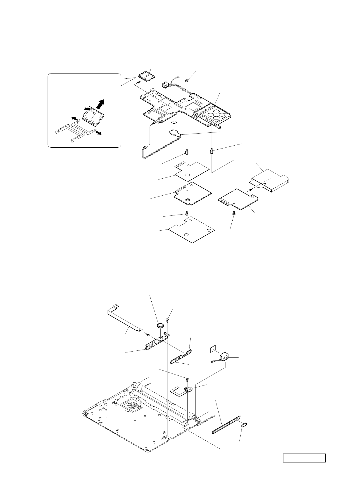
7. MBX-44 Board, IFX-124 Board, DDC-3 Board, V/L Rechargeable Battery
Order of releasing the
SO-DIMM
A → C
B
A
q; Hex Screw (MBX) (Silver)
5 Lock Ace
(M2X2.5 Special Flat) (Silver)
C
A
8 Insulator (MBX)
7 DDC-3 Board
Memory Module
qa
9 Nut M2
qd MBX-44 Board
qs V/L Rechargeable Battery
4 Hex Screw (MBX) (Silver)
3 Insulator IFX-108
2 IFX-124 Board
8. CNX-107 Board
3 FFC (MBX-34-CNX-96)
5 CNX-107 Board
6 Lock Ace (M2X3.5) (Gold)
6 Insulator DDC-2
4 Dial Assy
1 Lock Ace
(M2X2.5 Special Flat) (Silver)
1 Lock Ace (M2X3.5) (Gold)
2 Escutcheon (RF)
q; Modular Harness
Claw
7 Flexible Print PWB
8 Escutcheon (RB) Assy
9 Cap Modem
Confidential
1-5 PCG-SR27/SR27K (UC)
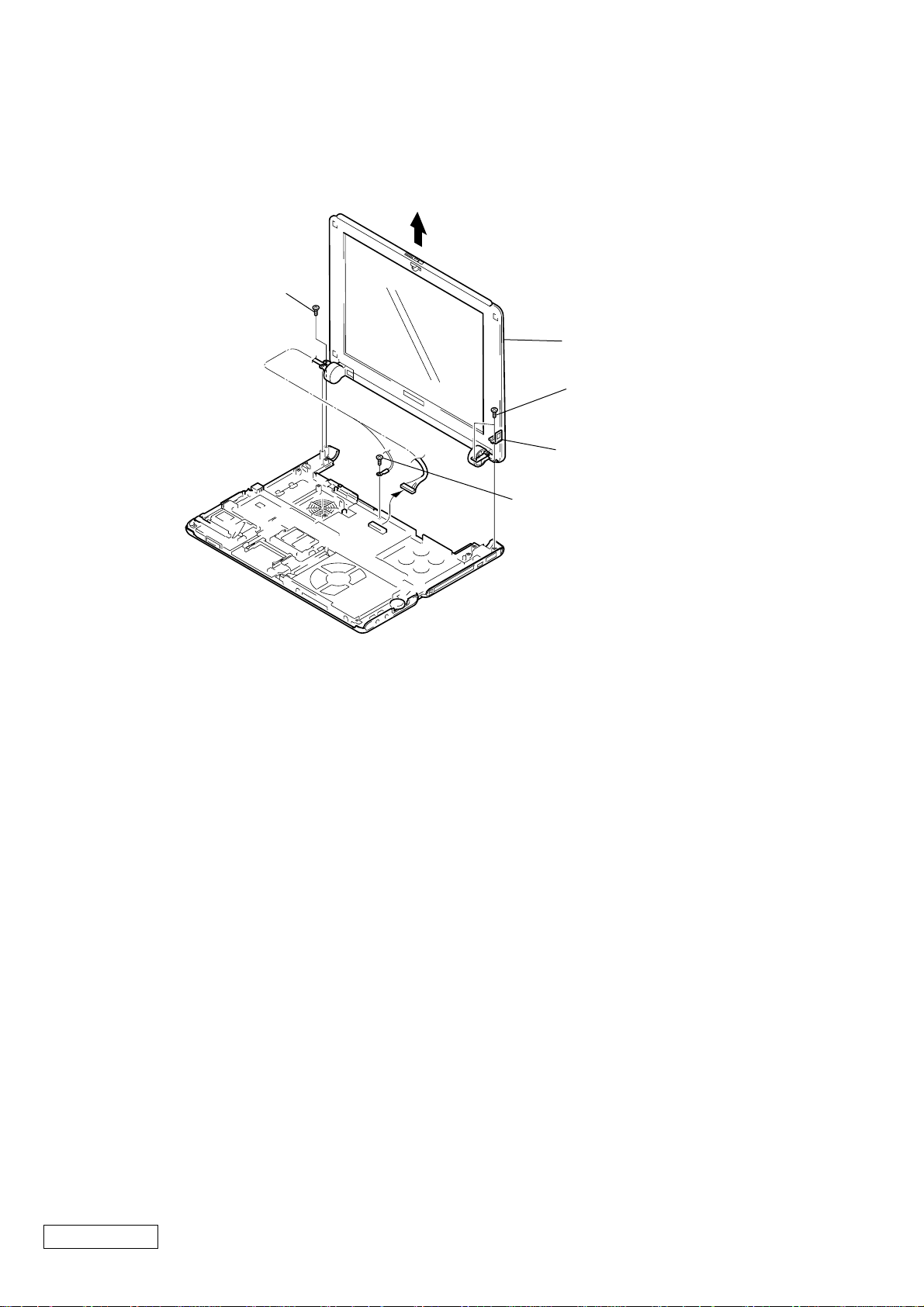
9. Display Assy
3 Lock Ace (M2.6X4) (Silver)
6
7 Display Assy
4 Lock Ace
(M2.6X4) (X2) (Silver)
5 Plate
1
2 Lock Ace (M2X3.5) (Gold)
Confidential
1-6PCG-SR27/SR27K (UC)
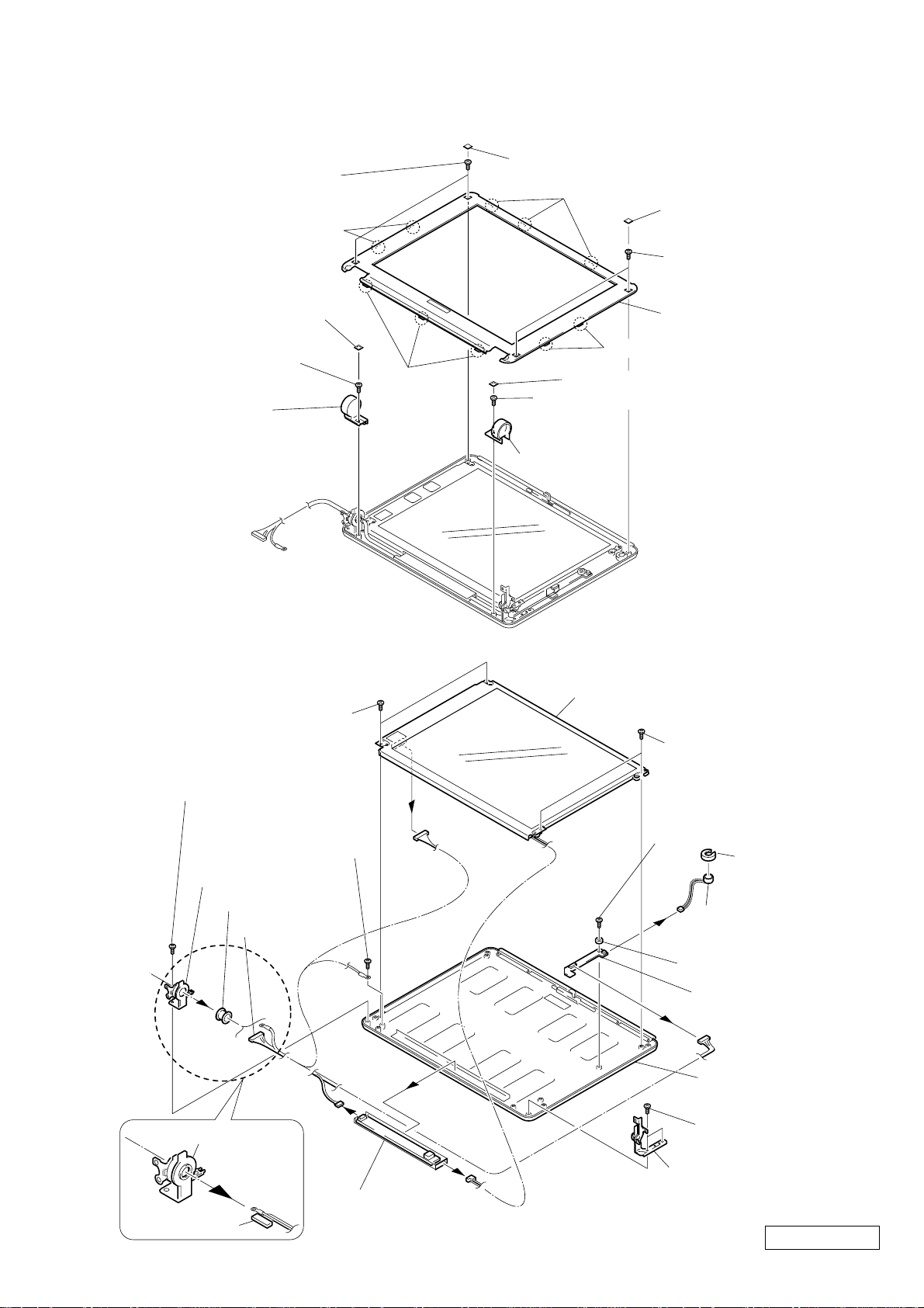
10. LCD Section – Made by TS –
1. Housing (Bezel) Assy
2 Lock Ace
(M2X4) (X2) (Silver)
Two Claws
1 Screw Blind (X2)
Three Claws
3 Screw Blind (X2)
4 Lock Ace
(M2X4) (X2) (Silver)
6 Screw Blind
7 Lock Ace
(M2X4) (Silver)
Three
8 Cover (L)
Claws
q; Lock Ace (M2X4) (Silver)
qa Cover (R)
2. Microphone, LCD Assy, Inverter Unit, ANL-24 Board
qs +B 2.6X2.5 (X2) (Gold)
5 Housing (Bezel) Assy
Two Claws
9 Screw Blind
qf LCD Assy
qs +B 2.6X2.5 (X2) (Gold)
qh Lock Ace
(M2.6X4) (X2) (Silver)
qg Lock Ace
(M2X4) (Silver)
ql Tilt (L)
qk Bushing
qj LCD Harness
Tilt (L), Bushing
LCD Harness
qd
8
9
qa Inverter Unit
4 Lock Ace (M2X4) (Black)
1 Holder
(Microphone)
2
3 Electret Condenser
Microphone
5 Bushing (PC Board)
7 ANL-24 Board
6
Housing
(Display) Assy
w; Lock Ace
(M2.6X4) (X2) (Silver)
wa Tilt (R)
q;
Confidential
1-7 PCG-SR27/SR27K (UC)
(END)

CHAPTER 2.
SELF DIAGNOSTICS
ATTENTION
Please confirm “Self Diagnostics” method which will be informed you with distribution
of “Self Diagnostics” software.
Confidential
2-1 PCG-SR27/SR27K (UC)
(END)
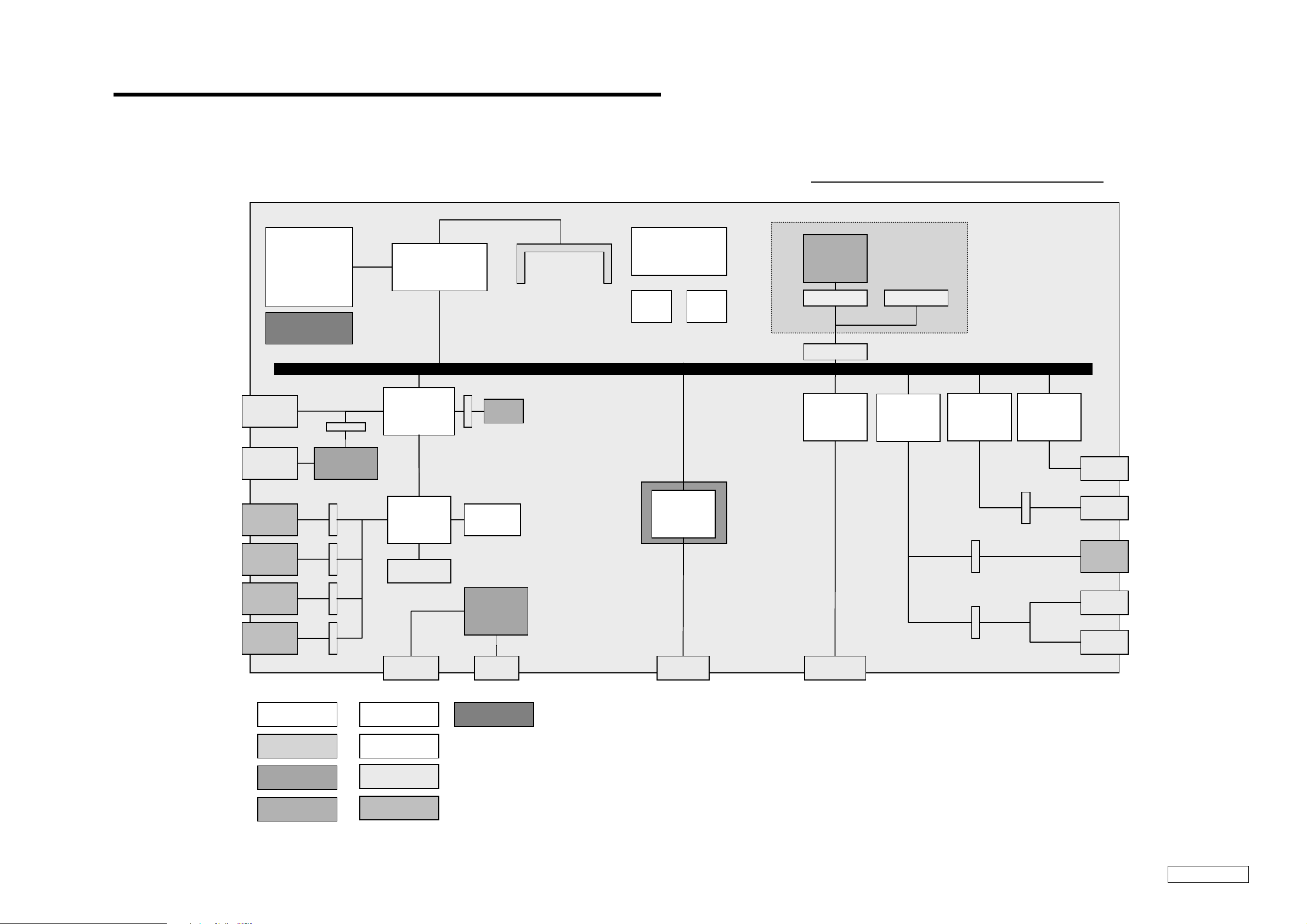
CHAPTER 3.
BLOCK DIAGRAM
PCG-SR Series Block Diagram
Pentium
Cooling FAN
USB
MS CN
TouchPad
JOG Dial
III
Memory
Stick
443ZX-100M
PIIX4E
H8
Port80/JIG
HDD
BIOS
(Onboard)
µ
DIMM
(2slot)
PCI bus
CPU core
Power Supply
Clock
Gen
Temp
sensor
Modem
Connexant
LCD
10.4”
Inverter
LCD CN
S3
Savage/IX
Internal MIC
YAMAHA
YFM754
i.LINK
Snowy
PCcard
R5C475II
PCcard
i.LINK
Stereo
speaker
Keyboard
LED
Mother PWB
LCD unit
Sub PWB
UNIT
Battery
Large IC
INT CN
EXT CN
User I/F
Power
Supply
Cooling
Phone
MIC
RJ-11DC in
VGA
Confidential
3-23-1
(END)
PCG-SR27/SR27K (UC)
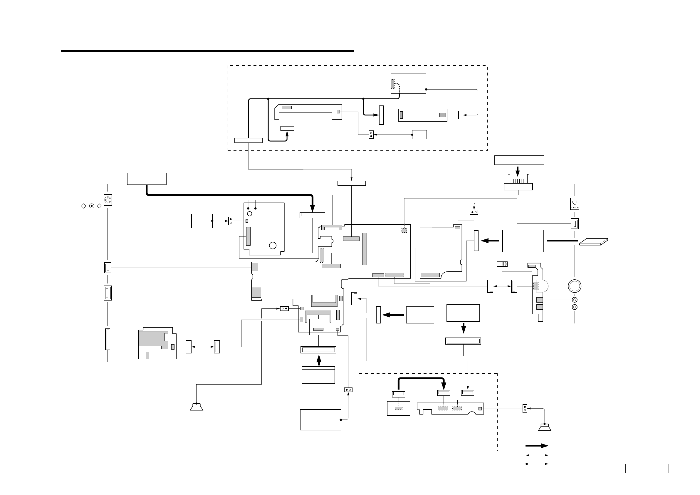
CHAPTER 4.
FRAME HARNESS DIAGRAM
DISPLAY ASSY
DC IN
CN351
DISPLAY
CN1902
USB
MEMORY
STICK
KEYBOARD
(CN2203)
NC
IFX-125
BOARD
(SIDE A)
CN2101
10
1
DC
FAN
DDC-3
BOARD
(SIDE A)
CN1901
2
10
CN502
1
9
ANL-24 BOARD
(SIDE A)
LCD HARNESS
LCD
INVERTER
1
4
CN3300
2
1
CN3301
MIC
BATTERY PACK
240
139
CN901
1
2
CN3151
25 1
CN301
MBX-44
BOARD
(SIDE A)
CN451
IFX-124
BOARD
(SIDE A)
1
2
CN401
68 34
CN5002
6
1
CN1502
PC
CARD
CONNECTOR
CN2601
24
1
CNX-107
BOARD
(SIDE A)
12
CN903
CN151
(CN806)
NC
CN1601
1143
2144
9110
CN902
2
CN5001 CN5000
12
49 50
CN1101
FPC
HDD
DRIVE
35 1
S2701
POWER
SWITCH
24
1
CN1802
RAM
2 144
CN152
1 143
SideSide
MODULER
JACK
i-LINK
PC
CARD
JOG DIAL
EXT MIC IN
HEADPHONE
PALM
RAM
1
(OPTION)
CN1503
2
110
112
CN1954CN1951
SPEAKER
VANADIUM
LITHIUM ION
BATTERY
TOUCH
PAD
SWX-61
BOARD
(SIDE A)
CN1955
4-24-1
(END)
1
2
SPEAKER
FROM board connector (direct connection)
Harness (connector at both end)
Harness (soldered at one end)
Confidential
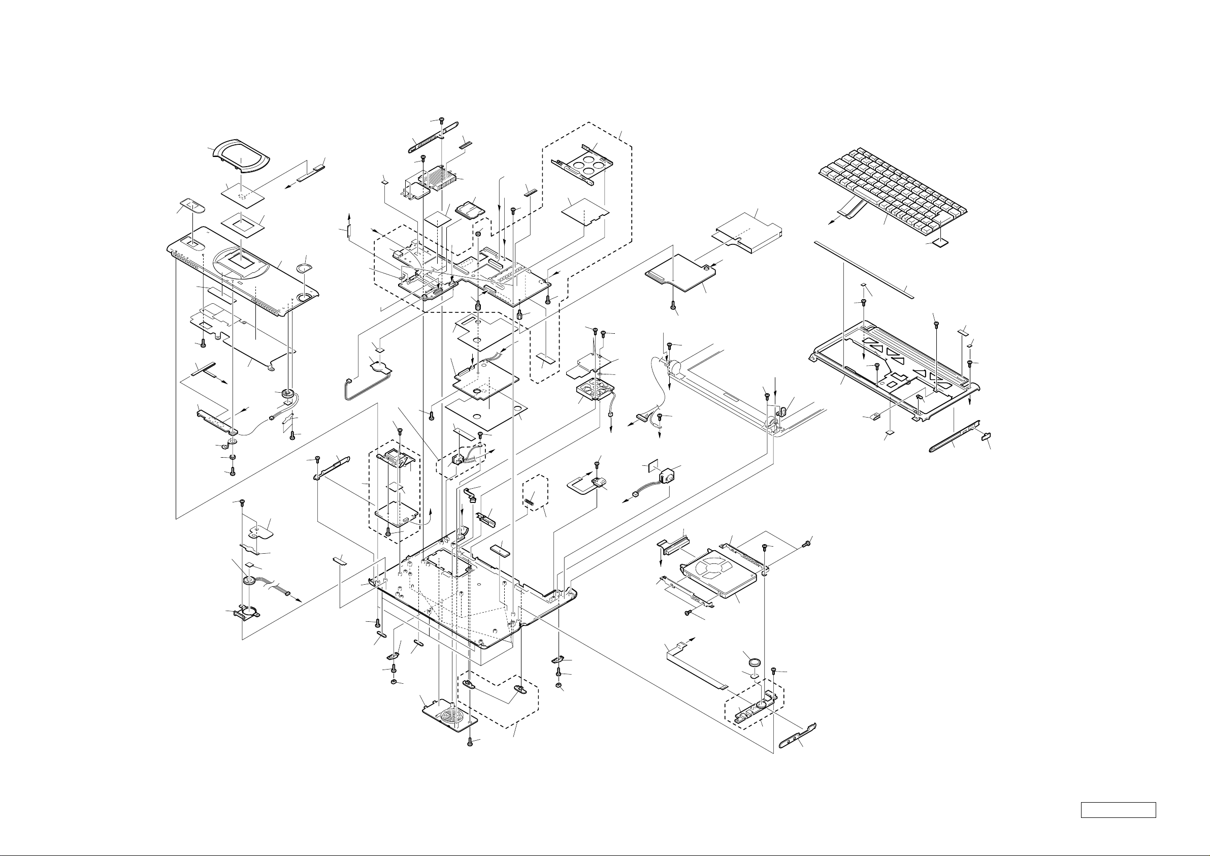
PCG-SR27/SR27K (UC)

EXPLODED VIEWS AND PARTS LIST
NOTE:
• The mechanical parts with no reference number in the
exploded views are not supplied.
• Items marked “ * ” are not stocked since they are seldom
required for routine service. Some delay should be
anticipated when ordering these items.
• When two or more parts are shown in parallel, use the
part described first as the main part.
CHAPTER 5.
The components identified by mark 0 or
dotted line with mark 0 are critical for safety.
Replace only with part number specified.
Les composants identifiés par une marque
0 sont critiques pour la sécurité.
Ne les remplacer que par une pièce portant
le numéro spécifié.
5-1
Confidential
PCG-SR27/SR27K (UC)

5-1. Main Section
Ref.No. Part No. Description Ref.No. Part No. Description
* 1 4-646-973-02 DUCT (L)
2 1-529-660-21 SPEAKER, (2.0CM)
4 4-644-492-31 ACE (M2), LOCK
5 4-644-492-51 ACE (M2), LOCK
6 X-4622-725-2 ESCUTCHEON (LF) ASSY
74 4-647-181-01 HEX SCREW (MBX)
* 75 4-646-732-01 BRACKET (B)
76 1-794-546-11 CONNECTOR, MEMORY STICK, EJECTOR
77 A-8066-718-A IFX-125 WHITE COMPLETE PWB
78 7-622-205-05 NUT M2 TYPE2
8 4-650-469-01 FOOT
9 X-4623-153-1 HOUSING (BOTTOM) ASSY
10 4-650-608-01 LID (HEAT) (A)
14 4-647-207-01 BUSHING (FAN)
15 4-644-493-11 ACE (M2.6), LOCK
16 4-635-956-01 SPRING (B), COMPRESSION COIL
18 4-647-535-01 INSULATOR RJ-11
19 1-794-537-11 HARNESS, MODULAR
20 1-678-628-11 PWB, FLEXIBLE PRINT
21 1-678-659-12 FPC (HDD)
* 22 4-646-726-01 BRACKET (F)
23 1-792-890-11 FFC (MBX-34-CNX-96)
24 4-646-724-01 ESCUTCHEON (RF)
25 4-635-301-01 SCREW M3X4
26 A-8025-092-A ASSY HDD 30GB (TOSHIBA) (S)
27 A-8066-712-A CNX-107 COMPLETE PWB
28 X-4622-918-2 DIAL ASSY
29 4-644-492-01 ACE (M2), LOCK
31 4-647-547-01 BUSHING (PC BOARD)
32 A-8066-515-A SWX-61 COMPLETE PWB
33 4-647-538-11 COOLING (1)
34 1-792-891-11 FFC (MBX-34-SWX-55)
35 4-648-320-01 TAPPING (M2)
36 1-529-660-31 SPEAKER, (2.0CM)
39 4-646-718-02 ESCUTCHEON (PAD)
40 1-772-529-21 PAD, TOUCH
41 1-792-893-11 FFC (SWX-55-TOUCH PAD)
42 4-646-814-01 WINDOW (JOG)
43 X-4622-697-5 HOUSING (PARM REST) ASSY
44 8-749-019-02 IC M463S1724CNO-L1L (128MB)
79 4-646-800-01 CUSHION (BB)
80 4-646-794-01 WINDOW (MS)
81 4-654-747-01 (SR27)...LABEL (ID GU)
81 4-654-746-01 (SR27K)...LABEL (ID GZU)
82 4-648-304-01 BLIND (PC BOARD)
* 83 4-646-719-01 HOLDER, SPEAKER
84 4-646-720-02 SHEET
85 7-685-504-19 SCREW +BTP 2X6 TYPE2 N-S
87 4-648-505-01 TAPE (FRAME), COPPER LEAF
88 4-648-819-01 COVER KEYBOARD
89 4-648-847-02 INSULATOR (DC JACK)
92 4-646-730-02 INSULATOR (MBX)
93 4-648-438-01 PLATE
94 4-649-669-01 CUSHION IFX
95 4-648-624-01 INSULATOR PC CARD
96 4-649-299-01 WOVEN (SP), FABRIC NON
97 4-651-347-11 FINGER (KEY BOARD)
98 4-652-170-01 SHIELD (PARM)
99 4-651-335-01 SHEET (BUTTON)
100 4-651-354-01 SHIELD MS
101 4-651-421-01 CUSHION (HDD)
102 4-648-354-03 MS SEAT
103 7-621-772-35 SCREW +B 2X6
* 104 4-652-171-01 CONTACT (PARM)
105 1-960-621-21 HARNESS (WITH DC JACK)
109 4-653-511-01 PLATE (SWX), GROUND
111 1-695-514-21 JACK (SMALL TYPE) 1P
112 1-794-548-11 CONECTOR, USB (A)
117 4-655-508-01 SEAL (JOG)
118 4-655-783-02 SPEAKER, CUSHION
45 1-792-892-12 FFC (MBX-34-IFX-109)
46 4-648-140-11 SHEET (C), THERMAL
47 4-646-728-04 ESCUTCHEON (LB)
* 48 4-650-213-02 HEATSINK NT2
49 4-651-343-01 SHEET (NT2), THERMAL
51 1-794-553-11 CONNECTOR,PC CARD (EJECTOR)
52 A-8025-089-A C/P MBX-44 (P3/750LU/XGA) (S)
53 1-528-984-11 BATTERY, V/L RECHARGEABL
55 A-8066-714-A IFX-124 COMPLETE PWB
56 4-647-533-02 INSULATOR IFX-108
57 A-8066-723-A DDC-3 COMPLETE PWB
58 4-647-534-02 INSULATOR DDC-2
59 4-646-852-01 CLAMP
60 1-763-562-11 FAN, DC (UDQFSEH52)
61 X-4623-483-2 FRAME ASSY
62 4-648-125-01 ACE (M2 SPECIAL FLAT), LOCK
63 4-646-722-02 BLIND, SCREW
64 X-4623-616-1 ESCUTCHEON (RB) ASSY
65 4-647-168-02 CAP MODEM
66 1-476-148-23 KEY BOARD UNIT
68 4-651-383-01 SHEET (TOUCH PAT) (2)
69 4-646-713-01 BASE (L), FOOT
70 4-646-708-01 FOOT, REAR
71 4-646-725-03 BUTTON, POWER
73 4-647-181-11 HEX SCREW (MBX)
119 4-653-077-11 SPACER (PARM REST)
Confidential
PCG-SR27/SR27K (UC)
5-2
80
35
99
34
32
39
109
31
35
40
5
105
92
57
49
D
89
97
74
K
C
33
44
78
A
15
14
59
4
G
97
H
5
J
58
J
94
Supplied
with 9
Included in 9
95
L
4
73
85
82
60
L
16
Included
in 9
69
15
70
47
41
46
B
45
F
E
112
104
I
79
53
6
77
118
9
29
8
15
68
42
43
98
D
5
2
1
B
36
96
83
35
5
100
83
96
E
Included
in 57
5
69
62
76
102
4
8
70
5
F
10
51
52
56
N
M
55
62
18
22
I
R
5
S
75
117
111
15
93
25
5
26
28
5
27
24
C
15
H
19
21
25
23
A
5
48
119
G
K
5
20
M
29
61
R
87
29
63
101
66
84
88
71
29
64
81
63
103
S
65
PCG-SR27/SR27K (UC)5-3 5-4
Confidential
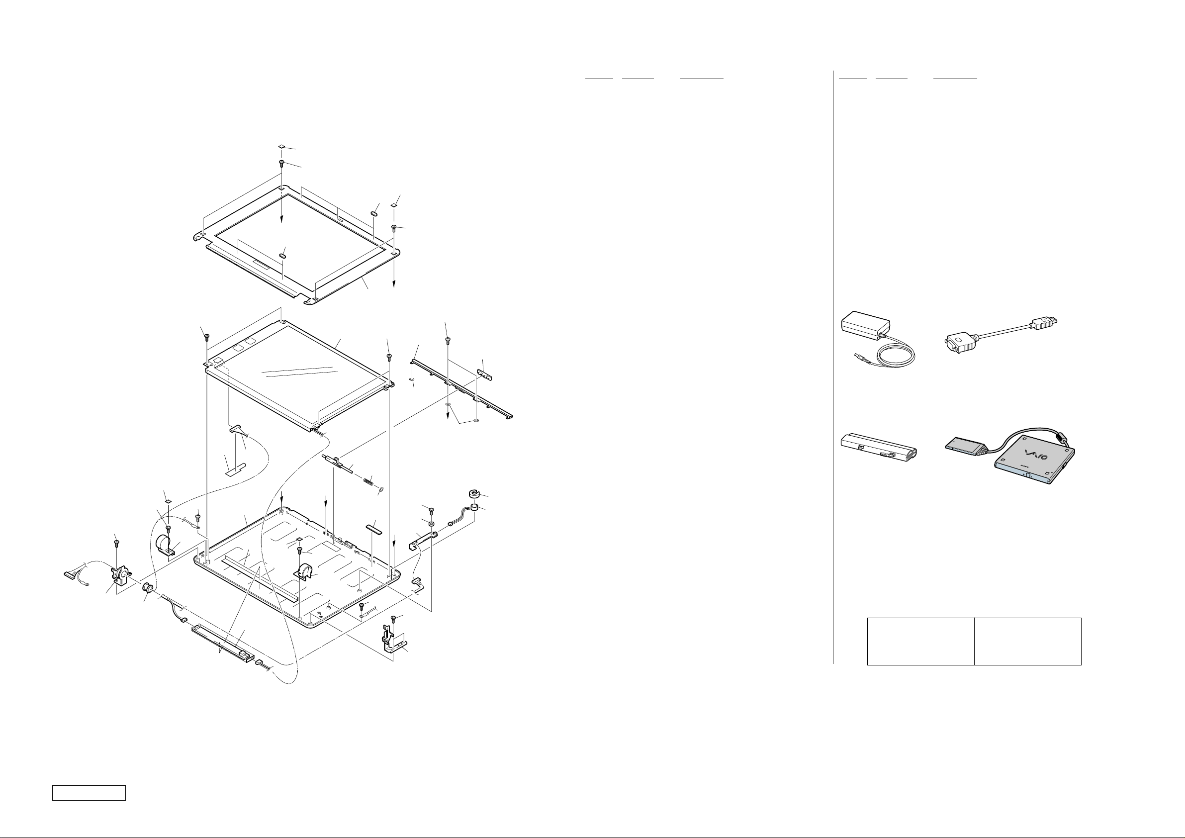
5-2. LCD Section – Made by TS –
301
303
O
330
309
305
304
330
309
P
301
303
306
351
333
Q
350
308
Ref.No. Part No. Description Ref.No. Part No. Description
301 4-646-977-01 BLIND (LCD), SCREW
303 4-644-492-31 ACE (M2), LOCK
ACCESSORIES
************
304 X-4623-481-1 HOUSING (BEZEL) ASSY
305 A-8045-747-A LCD ASSY (S)
306 4-646-705-02 TUBE, TOP
0 401 1-476-163-13 ADAPTOR, AC
402 1-756-100-21 BATTERY PACK, LITHIUM ION
403 1-757-026-11 CABLE, VGA
308 4-646-703-01 KNOB (LATCH)
309 4-639-890-01 SCREW (+B M2.6X2.5)
311 4-646-704-02 LEVER (LATCH)
0 1-757-562-21 CORD, POWER
4-653-282-11 MANUAL, INSTRUCTION
(PCGA-CD51 Series)
312 4-635-923-01 HOLDER (MICROPHONE)
314 1-542-402-21 MICROPHONE, ELECTRET CONDENSER
315 1-960-481-11 HARNESS, LCD
317 4-639-623-11 SPRING (LATCH), COIL
LOOK AT EXPLODED VIEWS OF THE PART
**********************************
318 4-644-493-11 ACE (M2.6), LOCK
319 4-646-791-11 TILT (L)
404 PCGA-CD51/A
320 4-646-706-11 COVER (L)
323 4-646-792-11 TILT (R)
324 1-418-085-41 INVERTER UNIT
325 4-646-722-02 BLIND, SCREW
326 4-646-700-11 COVER (R)
327 4-647-482-02 SEAL (LVDS)
328 X-4622-700-2 HOUSING (DISPLAY) ASSY
401
Adaptor AC
403
Display Adaptor
329 4-646-975-01 BUSHING
330 4-646-976-02 CUSHION (LATCH)
331 4-648-793-01 WASHER (LATCH)
332 4-648-451-01 SPACER
333 7-621-772-00 SCREW +B 2X3
348 A-8066-505-A ANL-24 COMPLETE PWB
349 4-647-547-01 BUSHING (PC BOARD)
350 4-653-077-01 SPACER (PARM REST)
351 4-653-077-11 SPACER (PARM REST)
402
Battery Pack
404
CD-ROM Drive (PCGA-CD51/A)
352 4-656-225-01 LCD HARNESS GUIDE SHEET
319
318
329
303
325
320
303
327
328
324
315
352
325
O
303
Q
326
311
317
331
332
303
P
303
349
348
318
323
312
314
• The CD-ROM Drive itself does
not have the Part No.
Refer to the PCGA-CD51 Series
Service manual (9-928-323-12).
The components identified by
mark 0 or dotted line with mark
0 are critical for safety.
Replace only with part number
specified.
Les composants identifiés par
une marque 0 sont critiques
pour la sécurité.
Ne les remplacer que par une
pièce portant le numéro spécifié.
Confidential
PCG-SR27/SR27K (UC)
5-5 5-6
(END)

VAIO® Notebook
Includes PCG-SR33 Update Notice
Quick Start
PCG-SR27/PCG-SR27K

Contents
1 Welcome ..........................................................5
Features.......................................................................................... 5
Unpacking Your Notebook.............................................................. 6
Notes on Use.................................................................................. 7
2 Setting Up Your VAIO® Notebook ...............11
Locating Controls and Connectors ............................................... 11
Connecting a Power Source .........................................................14
Starting Your Notebook................................................................ 20
Registering Your Notebook ..........................................................21
Shutting Down Your Notebook..................................................... 22
3 Power Saving Modes ....................................23
4 About the Software on Your Notebook .......27
Overview....................................................................................... 27
Application, Driver, and System Recovery CDs ............................32
Software Support Information...................................................... 36
5 Getting Help...................................................39
VAIO Support Agent .....................................................................40
3

VAIO® Notebook Quick Start
6 Troubleshooting ........................................... 51
Troubleshooting Your Notebook ...................................................51
Troubleshooting the LCD Screen ..................................................55
Troubleshooting the Mouse and Touchpad...................................56
Troubleshooting Drives, PC Cards, and Peripheral Devices ..........57
Troubleshooting Software.............................................................59
Troubleshooting the Modem.........................................................60
Troubleshooting Audio..................................................................61
Troubleshooting the Printer ..........................................................62
7 Index .............................................................. 63
4

Welcome
Congratulations on your purchase of the Sony VAIO® notebook. Sony has
combined leading-edge technology in audio, video, computing, and
communications to provide you with state-of-the-art personal computing.
Features
✍ For a complete description of the specifications of your VAIO Notebook, see “VAIO
Notebook Specifications” .
❑ Exceptional performance — Your notebook includes a fast low voltage
Mobile Intel
SpeedStep™ technology and a V.90/K56flex compatible modem.
❑ Portability — The high-capacity lithium-ion battery provides hours of use
without AC power.
❑ Sony audio and video quality — High-quality MPEG1 digital video,
which supports full-screen display (10.4-inch Active Matrix LCD screen)
and enables you to take advantage of today’s advanced multimedia
applications, games, and entertainment software.
❑ Microsoft
Microsoft
2000 Professional operating system.
❑ Communications — Access popular online services, send e-mail, and
browse the Internet.
❑ Optical drive (CD-ROM) — The CD-ROM drive utilizes a new optical
storage technology that provides a rich multimedia computing experience.
* Actual upload and download speeds may vary due to line conditions, ISP support, and gov-
ernment regulations.
®
Pentium® III processor 750MHz featuring Intel®
®
Windows® operating system — Your system includes the
®
Windows® Millennium Edition or the Microsoft® Windows®
*
5
VAIO® Notebook Quick Start
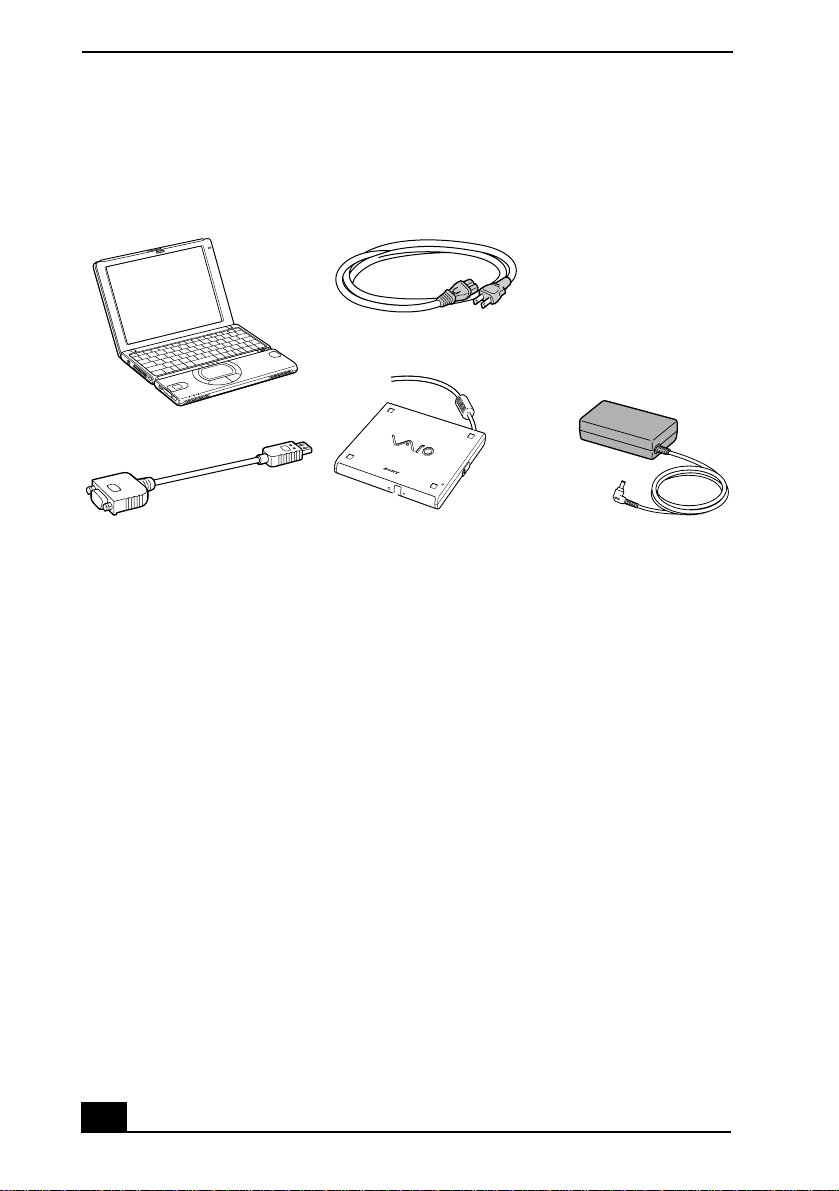
Unpacking Your Notebook
Hardware:
Main Unit
VGA Adapter
Power Cord
Optical Drive
AC Adapter
Documents
❑ VAIO
❑ The Microsoft
❑ Legal/Safety Information — Explains notes on use and offers safety tips.
❑ Specifications — Details the hardware specifications for your notebook.
®
Notebook Quick Start — Contains information on unpacking and
setting up your notebook, the features of your notebook, the applications
included with your system, and how to contact software vendors and solve
common problems.
®
Windows® Millennium Edition Getting Started document
or Microsoft
®
Windows 2000 Professional Getting Started document —
Explains how to use the basic features of the Windows operating system.
Software CDs
❑ Microsoft
the Sony computer you purchased.
6
®
Word 2002 — Allows you to reinstall Microsoft Word 2002 to

Notes on Use
Recovery CDs
❑ Application Recovery CD(s) — Enables you to reinstall individual
applications if they become corrupted or erased.
❑ Driver Recovery CD(s) — Enables you to reinstall individual device
drivers. Use it to restore corrupted or erased device drivers.
❑ System Recovery CD(s) — Enables you to format the C:\ partition of the
hard disk drive, then reinstall the operating system and software titles that
shipped with your notebook if they become corrupted or are erased.
Other
❑ Packet containing special product offers
❑ Warranty card
Notes on Use
You will be using your notebook computer as a portable device in a variety of
environments. Whenever possible, you should apply the following ergonomic
considerations to both stationary and portable environments.
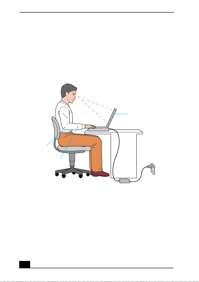
Ergonomic Guidelines
❑ Position of your notebook — Place the notebook directly in front of you as
you work. Keep your forearms horizontal, with your wrists in a neutral,
comfortable position while using the keyboard, touchpad, or external mouse.
Let your upper arms hang naturally at your sides. Take breaks during
sessions with your notebook. Excessive use of the notebook may strain
muscles or tendons.
❑ Furniture and posture — Sit in a chair with good back support and
armrests. Adjust the level of the chair so your feet are flat on the floor. A
footrest may make you more comfortable. Sit in a relaxed, upright posture
and avoid slouching forward or leaning far backward.
❑ Viewing angle of the notebook’s display — Use the display’s tilting
feature to find the best position. You can reduce eye strain and muscle
fatigue by adjusting the tilt of the display to the proper position. You can
adjust the brightness setting of the display also.
7
VAIO® Notebook Quick Start
❑ Lighting — Choose a location where windows and lights do not create glare
or reflection on the display. Use indirect lighting to avoid bright spots on the
display. You can also purchase accessories for your display that help reduce
glare. Proper lighting adds to your comfort and work effectiveness.
❑ Placement of an external display — When using an external display, set
the display at a comfortable viewing distance. Make sure the display screen
is at eye level or slightly lower when you are sitting in front of the monitor.
Recommended Position
Computer positioned
directly in front of you
Arms at desk
level
Wrists relaxed
and flat
Setting Up Your Notebook
❑ Do not place your notebook in a location subject to:
❑ Heat sources, such as radiators or air ducts
❑ Direct sunlight
❑ Excessive dust
❑ Moisture or rain
❑ Mechanical vibration or shock
❑ Strong magnets or speakers that are not magnetically shielded
❑ Ambient temperature of more than 95º F (35º C) or less than
40º F (5º C)
❑ High humidity
8

Notes on Use
❑ Do not place electronic equipment near your notebook. The notebook’s
electromagnetic field may cause a malfunction.
❑ Provide adequate air circulation to prevent internal heat build-up. Do not
place your notebook on porous surfaces such as rugs or blankets, or near
materials such as curtains or draperies that may block its ventilation slots.
Leave a space of at least 8 inches behind the back panel of the notebook.
❑ The notebook uses high-frequency radio signals and may cause interference
to radio or TV reception. Should this occur, relocate the notebook a suitable
distance away from the set.
❑ Use only specified peripheral equipment and interface cables; otherwise,
problems may result.
❑ Do not use cut or damaged connection cables.
❑ Your notebook will not work with party lines, cannot be connected to a coin-
operated telephone, and may not work with multiple phone lines or a private
branch exchange (PBX).
❑ If the telephone company makes a service call to your home or office and
determines that your notebook is responsible for a problem, the telephone
company may bill you for the service call. Also, if you do not disconnect
your notebook when it is adversely affecting the telephone line, the
telephone company has the right to disconnect your service until you correct
the problem.
Handling Your Notebook
❑ Clean the cabinet with a soft, dry cloth or a soft cloth lightly moistened with
a mild detergent solution. Do not use any type of abrasive pad, scouring
powder, or solvent such as alcohol or benzine, as these may damage the
finish of your notebook.
❑ Should any solid object or liquid fall into the notebook, shut down your
notebook and then unplug it. You may want to have the notebook checked by
qualified personnel before operating it any further.
❑ Do not drop the notebook or place heavy objects on top of the notebook.
9

VAIO® Notebook Quick Start
Cleaning Your Notebook
❑ Make sure to disconnect the AC adapter before cleaning the notebook.
❑ Avoid rubbing the LCD screen as this can damage the screen. Use a soft, dry
cloth to wipe the LCD screen.
❑ Clean the notebook with a soft cloth lightly moistened with a mild detergent
solution. Do not use any type of abrasive pad, scouring powder or solvent,
such as alcohol or benzine.
Handling the LCD Screen
❑ Do not leave the LCD facing the sun as it can damage the LCD. Be careful
when using the notebook near a window.
❑ Do not scratch the LCD or exert pressure on it. This could cause
malfunction.
❑ Using the notebook in low temperature conditions may produce a residual
image on the screen. This is not a malfunction. When the notebook returns to
normal temperature, the screen returns to normal.
❑ A residual image may appear on the screen if the same image is displayed
for a lengthy period of time. The residual image disappears in a while. You
can use a screen saver to prevent residual images.
❑ The screen becomes warm during operation. This is normal and does not
indicate a malfunction.
❑ The LCD is manufactured using high-precision technology. You may,
however, see tiny black points and/or bright points (red, blue, or green) that
continuously appear on the LCD. This is a normal result of the
manufacturing process and does not indicate a malfunction.
On Moisture Condensation
❑ If the notebook is brought directly from a cold location to a warm one,
moisture may condense inside your notebook. In this case, allow at least an
hour before turning on your notebook. If any problems occur, unplug your
notebook, and contact your Sony Service Center.
10
Setting Up Your VAIO® Notebook
This section describes the controls and connectors on your VAIO
Notebook, how to connect your notebook to a power source, and how to
start and shut down your notebook
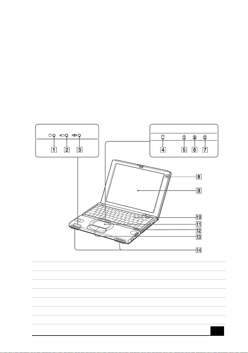
Locating Controls and Connectors
Front
1 Power Indicator 8 Microphone
2 Battery Indicator 9 LCD Screen
3 MG Memory Stick
4 Hard Disk Drive Indicator 11 Touchpad
5 Num Lock Indicator 12 Power Switch
6 Caps Lock Indicator 13 Left/Right Button
7 Scroll Lock Indicator 14 Speakers
®
Indicator 10 Keyboard
11
 Loading...