

Sony Vaio PCG-R505LE, Vaio PCG-R505LEK, Vaio PCG-R505ES, Vaio PCG-R505ESP, Vaio PCG-R505ESK Service Manual
...
PCG-R505EL/R505ELK/R505ES/
R505ESK/R505ESP
SERVICE MANUAL
Ver. 1-2002E
Revision History
Lineup: PCG-R505EL
PCG-R505ELK
PCG-R505ES
PCG-R505ESK
PCG-R505ESP
For American Area
US Model
Canadian Model
S400
Confidential
• Design and specifications are subject to
change without notice.
9-874-557-01
Notebook Computer

Information in this document is subject to change without notice.
Sony, VAIO and CLIE are trademarks or registered trademarks of
Sony. Microsoft, Windows, Windows Media, Outlook, Bookshelf
and other Microsoft products are trademarks or registered trademarks
of Microsoft Corporation in the United States and other countries.
The word Bluetooth and the Bluetooth logo are trademarks of
Bluetooth SIG, Inc. AMD, AMD logo, AMD Duron and
combinations thereof , 3DNow!, are trademarks of Advanced Micro
Devices, Inc. Intel Inside logo, Pentium and Celeron are trademarks
or registered trademarks of Intel Corporation.Transmeta, the
Transmeta logo, Crusoe Processor, the Crusoe logo and
combinations thereof are trademarks of Transmeta Corporation in
the USA and other countries. Graffiti, HotSync, PalmModem, and
Palm OS are resistered trademarks, and the Hotsync logo and Palm
are trademarks of Palm, Inc. or its subsidiaries. (M) and Motrola
are trademarks of Motrora, Inc. Other Motrola products and services
with (R) mark like Dragomball are the trademarks of Motrola, Inc.
All other names of systems, products and services in this manual
are trademarks or registered trademarks of their respective o wners.
In this manual, the (TM) or (R) mark are not specified.
Caution Markings for Lithium/Ion Battery - The following or similar
texts shall be provided on battery pack of equipment or in both the
operating and the service instructions.
CAUTION: Danger of explosion if battery is incorrectly replaced.
Replace only with the same or equivalent type recommended by
the manufacturer. Discard used batteries according to the
manufacturer’s instructions.
CAUTION: The battery pack used in this de vice may present a f ire
or chemical burn hazard if mistreated. Do not disassemble, heat
above 100°C (212°F) or incinerate.
Dispose of used battery promptly.
Keep away from children.
CAUTION: Changing the back up battery.
•Overcharging, short circuiting, reverse charging, multilation
or incineration of the cells must bi avoided to prevent one or
more of the following occurrences; release of toxic materials,
release of hydrogen and/or oxygen gas, rise in surface
temperature.
• If a cell has leaked or vented, it should be replaced
immediately while avoiding to touch it without any protection.
Service and Inspection Precautions
1. Obey precautionary markings and instructions
Labels and stamps on the cabinet, chassis, and components identify areas
requiring special precautions. Be sure to observe these precautions, as
well as all precautions listed in the operating manual and other associated
documents.
2. Use designated parts only
The set’s components possess important safety characteristics, such as
noncombustibility and the ability to tolerate large voltages. Be sure that
replacement parts possess the same safety characteristics as the originals.
Also remember that the 0 mark, which appears in circuit diagrams and
parts lists, denotes components that have particularly important safety
functions; be extra sure to use only the designated components.
3. Always follow the original design when
mounting parts and routing wires
The original layout includes various safety features, such as inclusion of
insulating materials (tubes and tape) and the mounting of parts above the
printer board. In addition, internal wiring has been routed and clamped so
as to keep it away from hot or high-voltage parts. When mounting parts or
routing wires, therefore, be sure to duplicate the original layout.
4. Inspect after completing service
After servicing, inspect to make sure that all screws, components, and wiring
have been returned to their original condition. Also check the area around
the repair location to ensure that repair work has caused no damage, and
confirm safety.
5. When replacing chip components...
Never reuse components. Also remember that the negati ve side of tantalum
capacitors is easily damaged by heat.
6. When handling flexible print boards...
•The temperature of the soldering-iron tip should be about 270C.
•Do not apply the tip more than three times to the same pattern.
•Handle patterns with care; never apply force.
Caution: Remember that hard disk drives are easily damaged by
vibration. Always handle with care.
– 2 –
Confidential
PCG-R505EL/R505ELK/R505ES/R505ESK/R505ESP
(AM)
TABLE OF CONTENTS
Section Title Page
CHAPTER 1. BLOCK DIAGRAM............................... 1-1
(to 1-2)
CHAPTER 2. FRAME HARNESS DIAGRAM........ 2-1
(to 2-2)
CHAPTER 3. EXPLODED VIEWS AND
PARTS LIST
3-1. Main Section.................................................................... 3-2
3-2. LCD Section .................................................................... 3-5
3-3. Accessories ...................................................................... 3-7
(to 3-7)
CHAPTER 4. OTHERS
4-1. Replacing the CPU .......................................................... 4-1
(to 4-2)
•Abbreviations
UC : US model / Canadian model
History of the changes is shown as the “Revision
History” at the end of this data.
– 3 –
Confidential
PCG-R505EL/R505ELK/R505ES/R505ESK/R505ESP
(AM)
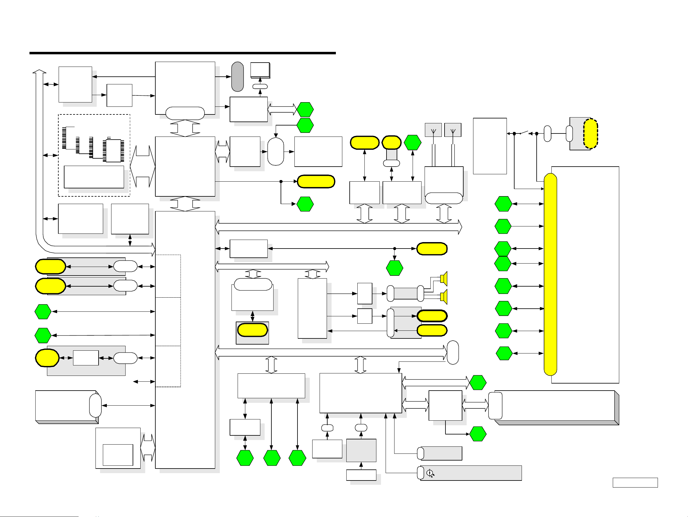
CHAPTER 1.
BLOCK DIAGRAM
USB
Port0
USB
Port1
USB Port5
5
USB Port6
6
VID
VID
Selector
Selector
FM3565
FM3565
On Board Memory
256Mbit x 4
PC133 SO-DIMM
PC133 SO-DIMM
144P Socket
144P Socket
Row#2, 3
CLK GEN
CLK GEN
IMI9870GTD
IMI9870GTD
(CK-Titan)
(CK-Titan)
SMBUS2
CNX-151
CNX-153
Row#0
Row#2, 3
Core
Voltage
Regulator
EEPROM
EEPROM
(Password)
(Password)
(ROMINFO)
(ROMINFO)
FFC
CN
FFC
CN
PC133
Memory
BUS
Pentum III-m
Pentum -m
Processor
Connector
GMCH-M
GMCH-M
FW82830MG
ICH3- M
Port0
USB Host
Controller0
Port1
Port2
USB Host
Controller1
Port3
CPU
CPU
&
&
Celeron
Celeron
Processor
uF CPGA
+
AGTL
FW82830MG
HL
ICH3- M
FW82801
FW82801
DVO
B
FAN
ITP
CN
Connector
ATF Sense
ATF Sense
FAN Control
FAN Control
ADM1030
ADM1030
VCH
VCH
FW82807
FW82807
Ether
Ether
82562
82562
MDC
Connector
MDC
MDC
RJ-11
CNX-1 5 2
SMBUS1
LCD
I/F
30pin
AC LINK
SMBUS1
1
LED Caps/Num/ScrLk
2
LCD 12.1" X GA
&
Inverter Board
LEX-32
VGA
DSub-15
VGA
4
PCI
Audio
Audio
CODEC
CODEC
YMF753
YMF753
PC Card
Socket
Cardbus
Cardbus
R5C476II
R5C476
Amp
Amp
Amp
i.LINK
0
FPC
CN
i.LINK
i.LINK
TSB43AB22
TSB43LV22
7
Ether
SWX-87
CN
SWX-151
CN
i.LINK
1
3
Diversity Antenna
IFX-182 IFX-183
W-LAN
W-LAN
Mod ule
Mod ule
802.11b
802.11b
Mini PCI
124pin
RJ-45
Speaker
CN
Headphone
Ext-MIC
Power
Supply
3.3V&5V
1.2V&1.8V
1.5V
Batt Charge
i.LINK
1
VGA
USB
Port5
USB
Port6
Ether
Serial
Pallarel
CN
CN
DC Jack
3
4
5
6
PCGA-DSM51
7
8
Docking Connector 100Pin
9
MS
Slot
HDD
MS
Chip
IFX-1 80
FPC
50pin
FFC
CN
N.C
FWH
FWH
E82802
E82802
Flash
BIOS R OM
8 Mbit
HL
Port4
USB Host
Controller2
Port5
Primary IDE
1-1 1-2
Serial
Serial
Buffer
Buffer
MA X3243
MA X3243
8 9
Super I/O
Super I/O
LPC47N227
LPC47N227
10
PallarelSerial FDD
LPC
CN
Int. KB D
Int. KB D
EC/KBC/SPIC
EC/KBC/SPIC
H8S/2149
H8S/2149
CN
JogDial
L/R Butto n
SWX-88
Touch PA D
Touch PA D
SMBUS0
FDD
Por t
Debug
SMBUS1
I/O Expande r
I/O Expande r
/SMBUS MU X
/SMBUS MU X
OZ998
OZ998
1
SMBUS0
2
Power SW
CN
SWX-87
FPC LED PWR/BATT/MS/W-LAN
CN
10
SMBUS1
Battery
Connector
LED Caps/Num/ScrLk
PCG-R505EL/R505ELK/R505ES/R505ESK/R505ESP
(END)
Baterry
BP2R/BP4R
Confidential
(AM)
 Loading...