

Sony pcg-r505afe Service Manual
PCG-R505AFE
SERVICE MANUAL
Ver. 1-2001J
“Revision History” is appended to the end of
this manual.
Update
Lineup: PCG-R505AFE
For American Area
Latin Model
S400
Confidential
9-872-290-01
Notebook Computer
Information in this document is subject to change without notice.
Sony and VAIO are trademarks of Sony. Microsoft, MS-DOS,
Windows, the Windo ws 95, W indo ws 98, W indows 2000, W indo ws
ME and W indows XP logo are trademarks of Microsoft Corporation.
All other trademarks are trademarks or registered trademarks of
their respective owners. Other trademar ks and trade names may be
used in this document to refer to the entitles claiming the marks and
names or their produces. Sony Corporation disclaims any proprietary
interest in trademarks and trade names other than its own.
Caution Markings for Lithium/Ion Battery - The following or similar
texts shall be provided on battery pack of equipment or in both the
operating and the service instructions.
CAUTION: Danger of explosion if battery is incorrectly replaced.
Replace only with the same or equivalent type recommended by
the manufacturer. Discard used batteries according to the
manufacturer’s instructions.
CAUTION: The battery pack used in this de vice may present a fire
or chemical burn hazard if mistreated. Do not disassemble, heat
above 100°C (212°F) or incinerate.
Dispose of used battery promptly.
Keep away from children.
CAUTION: Changing the back up battery.
• Overcharging, short circuiting, reverse charging, multilation
or incineration of the cells must bi avoided to prevent one or
more of the following occurrences; release of toxic materials,
release of hydrogen and/or oxygen gas, rise in surface
temperature.
• If a cell has leaked or vented, it should be replaced
immediately while avoiding to touch it without any protection.
Service and Inspection Precautions
1. Obey precautionary markings and instructions
Labels and stamps on the cabinet, chassis, and components identify areas
requiring special precautions. Be sure to observe these precautions, as
well as all precautions listed in the operating manual and other associated
documents.
2. Use designated parts only
The set’s components possess important safety characteristics, such as
noncombustibility and the ability to tolerate large voltages. Be sure that
replacement parts possess the same safety characteristics as the originals.
Also remember that the 0 mark, which appears in circuit diagrams and
parts lists, denotes components that have particularly important safety
functions; be extra sure to use only the designated components.
3. Always follow the original design when
mounting parts and routing wires
The original layout includes various safety features, such as inclusion of
insulating materials (tubes and tape) and the mounting of parts above the
printer board. In addition, internal wiring has been routed and clamped so
as to keep it away from hot or high-voltage parts. When mounting parts or
routing wires, therefore, be sure to duplicate the original layout.
4. Inspect after completing service
After servicing, inspect to make sure that all screws, components, and wiring
have been returned to their original condition. Also check the area around
the repair location to ensure that repair work has caused no damage, and
confirm safety.
5. When replacing chip components...
Never reuse components. Also remember that the negati ve side of tantalum
capacitors is easily damaged by heat.
6. When handling flexible print boards...
•The temperature of the soldering-iron tip should be about 270C.
•Do not apply the tip more than three times to the same pattern.
•Handle patterns with care; never apply force.
Caution: Remember that hard disk drives are easily damaged by
vibration. Always handle with care.
Confidential
PCG-R505AFE (AM)
– 2 –

TABLE OF CONTENTS
Section Title Page
CHAPTER 1. REMOVAL
1-1. Flowchart ......................................................................... 1-1
1-2. Main Electrical Parts Location Diagram ......................... 1-2
1-3. Removal ...........................................................................1-2
1. Key Board Unit ................................................................ 1-2
2. Palm Rest Section ............................................................1-3
3. SWX-72 Board, Encoder (Rotaly), Touch Pad ................ 1-3
4. IFX-141 Board ................................................................. 1-4
5. Battery.............................................................................. 1-4
6. HDD................................................................................. 1-5
7. Cover (Bottom LF/LR/R) ................................................ 1-5
8. Frame Housing................................................................. 1-6
9. SWX-76 Board, Speaker (L/R)........................................ 1-6
10. CNX-119 Board ............................................................... 1-7
11. Modem Card .................................................................... 1-7
12. CNX-121 Board ............................................................... 1-8
13. DC Fan ............................................................................. 1-8
14. MBX-48 Board ................................................................ 1-9
15. Heatsink (CPU)................................................................ 1-9
16. CNX-120 Board, LCD Section, CNX-131 Board ......... 1-10
17. Bezel .............................................................................. 1-11
18. LCD Unit ....................................................................... 1-11
19. LEX-29 Board, Inverter Unit ......................................... 1-12
(to 1-12)
CHAPTER 2. SELF DIAGNOSTICS.......................... 2-1
Please confirm “Self Diagnostics” method which will be informed
you with distribution of “Self Diagnostics” software.
CHAPTER 3. BLOCK DIAGRAM ............................... 3-1
(to 3-2)
CHAPTER 4. FRAME HARNESS DIAGRAM ........ 4-1
(to 4-2)
CHAPTER 5. EXPLODED VIEWS AND
PARTS LIST
5-1. Main Section ....................................................................5-2
5-2. LCD Section .................................................................... 5-5
5-3. Accessories ...................................................................... 5-7
(to 5-7)
– 3 –
Confidential
PCG-R505AFE (AM)
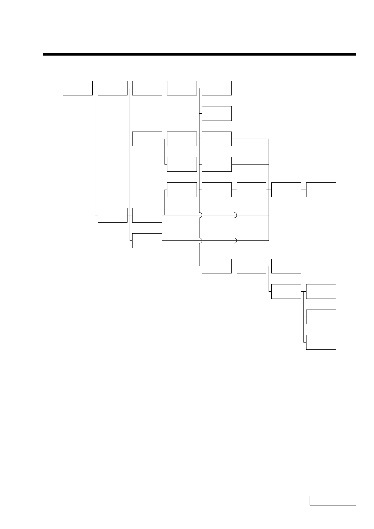
1-1. Flowchart
CHAPTER 1.
REMOVAL
POWER
OFF
KEY BOARD
UNIT
P 1-2
PALM REST
SECTION
P 1-3
COVER
(BOTTOM LF/
LR/R)
P 1-5
SWX-72
BOARD
P 1-3
IFX-141
BOARD
P 1-4
HDD
P 1-5
FRAME
HOUSING
P 1-6
ENCODER
(ROTARY)
P 1-3
TOUCH
PAD
P 1-3
BATTERY
P 1-4
SPEAKER
(L/R)
P 1-6
SWX-76
BOARD
P 1-6
CNX-119
BOARD
P 1-7
MODEM
CARD
P 1-7
CNX-121
BOARD
P 1-8
CNX-120
BOARD
P 1-10
DC
FAN
P 1-8
LCD
SECTION
P 1-10
MBX-48
BOARD
P 1-9
CNX-131
BOARD
P 1-10
HEATSINK
(CPU)
P 1-9
• P XX means pages that appears in this manual.
• Remember that hard disk drives are easily damaged by vibration. Always handle with care.
BEZEL
P 1-11
LCD
UNIT
P 1-11
LEX-29
BOARD
P 1-12
INVERTER
UNIT
P 1-12
1-1
Confidential
PCG-R505AFE (AM)
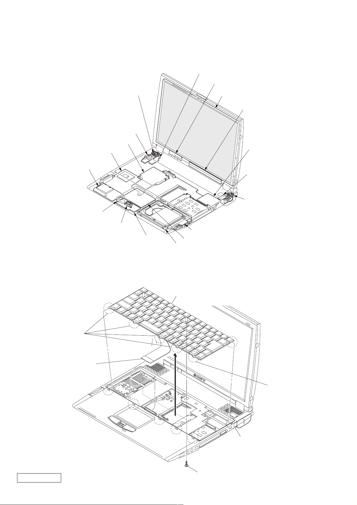
1-2. Main Electrical Parts Location Diagram
CNX-131 Board
LEX-29 Board
Speaker (L)
CNX-121 Board
LCD Unit
Inverter Unit
MBX-45 Board
IFX-141 Board
1-3. Removal
1. Key Board Unit
DC Fan
Battery
Encoder (Rotary)
SWX-72 Board
Modem Card
SWX-76 Board
Speaker (R)
CNX-119 Board
Touch Pad
HDD
Key Board Unit
2 Claw
4 Harness
Confidential
PCG-R505AFE (AM)
3
2 Claw
2 Claw
1 M2X6
1-2
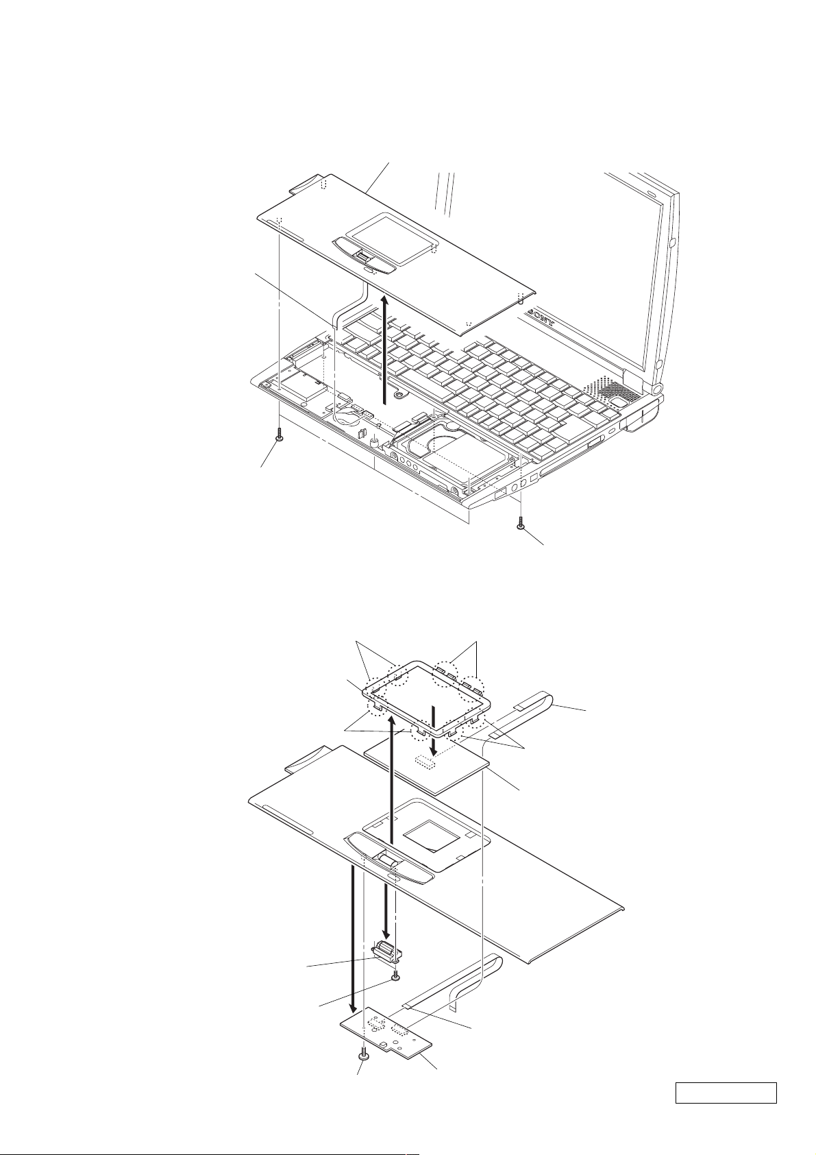
2. Palm Rest Section
3 Flexible Flat
Cable (10 core)
1 M2X6
Palm Rest Section
2
3. SWX-72 Board, Encoder (Rotaly), Touch Pad
7 Claw
8 Escutcheon (TP)
9
7 Claw
6
4
1 M2X6
7 Claw
2 Flexible Flat
Cable (12 core)
7 Claw
Touch Pad
Encoder (Rotary)
5 M1.4X3.5
3 M2X4
1 Flexible Flat Cable
(10 core)
SWX-72 Board
1-3
Confidential
PCG-R505AFE (AM)
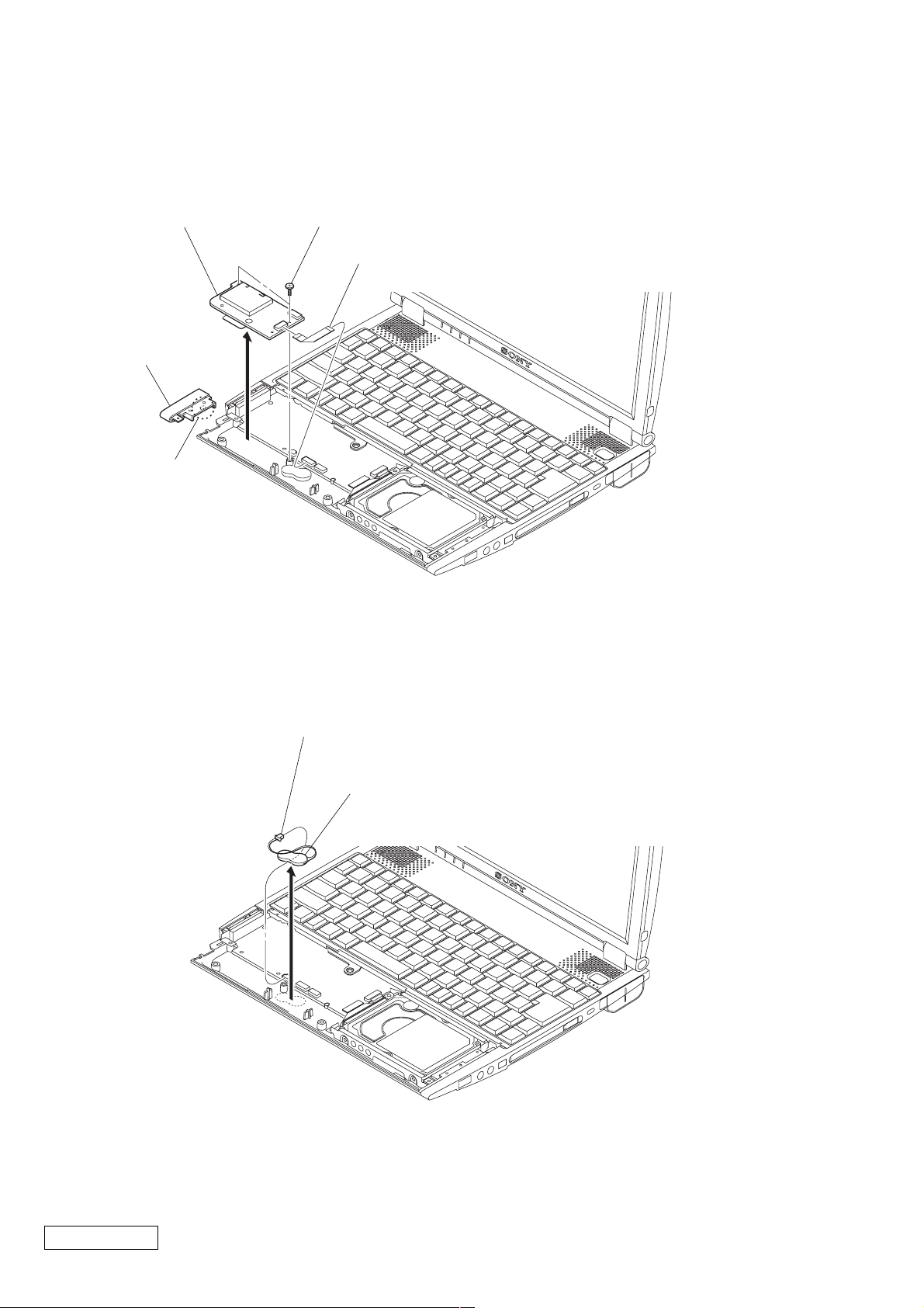
4. IFX-141 Board
IFX-141 Board
3 Cover (Bottom LF)
2 Claw
4 M2X4
1 Flexible Flat Cable (12 core)
5
5. Battery
1 Harness
Nickel Hydrogen Battery
2
Confidential
PCG-R505AFE (AM)
1-4
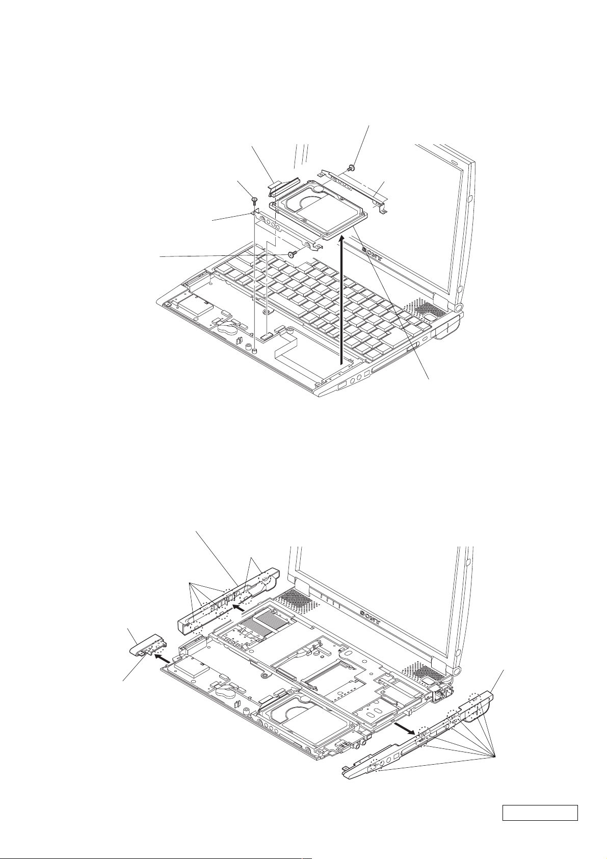
6. HDD
4 M3X4
1 FPC (HDD)
2 M2X4
7 Bracket (HDD F)
6 M3X4
7. Cover (Bottom LF/LR/R)
5 Bracket (HDD R)
3
HDD 30 GB
Cover
(Bottom LF)
1 Claw
Cover (Bottom LR)
3 Claw
2
3 Claw
4
1-5
Cover (Bottom R) Assy
6
5 Claw
Confidential
PCG-R505AFE (AM)
 Loading...