

NSR Series,Ipela NSR Series,Ipela NSR-1200,Ipela NSR-1100,Ipela NSR-1050H
Table of contents
 Loading...
Sony NSR Series,Ipela NSR Series,Ipela NSR-1200,Ipela NSR-1100,Ipela NSR-1050H User'smanual

Network
Surveillance
4-130-104-11 (2)
Server
User’s Guide
Before operating the unit, please read this manual thoroughly
and retain it for future reference.
NSR Series
© 2008 Sony Corporation

Table of Contents
Chapter 1 Introduction
Overview...........................................................................................6
Features and Functions ..................................................................8
System Requirements ...................................................................10
Reference Data for Installation.....................................................11
Front (When the Cover is Opened) ....................................................... 8
Rear ....................................................................................................... 9
Current Consumption and Inrush Current ........................................... 11
Storage Capacity for Recorded Data ................................................... 11
Recording Duration Guide .................................................................. 11
Number of Cameras............................................................................. 11
Chapter 2
Administration Menu
Overview.........................................................................................12
Displaying the Administration Menu ...........................................12
Changing Initial Settings with the Setup Menu...........................13
Displaying Setup Menu ....................................................................... 13
Details on Setting Items ...................................................................... 13
Configuring Settings Related to Servers.....................................20
Installing Patch Files.....................................................................21
Saving and Restoring Configuration Data ..................................22
Saving Configuration Data.................................................................. 22
Restoring Configuration Data ............................................................. 23
Exporting System Information .....................................................24
Chapter 3 Basic Operation
Overview.........................................................................................25
Logging On to the NSR .................................................................25
Basic Window Operations ............................................................27
Changing the Password................................................................29
Logging Off ....................................................................................29
Locking the NSR ............................................................................30
Shutting Down and Restarting the NSR ......................................30
Viewing Version Information ........................................................31
2
Table of Contents

Chapter 4
Application Settings
Alarms and Events ........................................................................32
Displaying Configuration Window ...............................................32
Registering Devices ......................................................................33
Selecting Automatically Detected Cameras and Registering Them
Simultaneously........................................................................... 33
Registering Devices Manually ............................................................ 35
Changing Registration Details............................................................. 36
Deleting Devices ................................................................................. 36
Settings Required when Using SNC-CS20/CM120/DS10/DM110/
DS60/DM160............................................................................. 37
Registering Device Groups ................................................................. 38
Details of Each Screen ........................................................................ 39
Configuring Camera Video Settings ............................................43
Configuring Camera Operations ..................................................44
Configuring Preset Positions ............................................................... 44
Configuring Camera Tours.................................................................. 45
Configuring Masks .............................................................................. 46
Configuring Control Protocol of Analog Camera ............................... 48
Configuring Network Camera Control................................................ 49
Configuring Audio .............................................................................. 49
Settings Related to Monitoring.....................................................50
Configuring Monitor Layout Settings ................................................. 50
Assigning Cameras to Monitor Frames............................................... 57
Configuring a Second Monitor............................................................ 57
Configuring Layout Tours................................................................... 58
Configuring Motion Detection Settings .......................................59
Using the Motion Detection Function of NSR (VMD (Recorder))..... 60
Using the Motion Detection Function of the Camera
(VMD (Camera)) ....................................................................... 62
Detecting Motion by Metadata (VMF) ............................................... 65
Configuring Settings Related to Storage ....................................70
Configuring Storage Settings .............................................................. 70
Configuring Settings Related to Deleting Recording Data ................. 73
Storage Configuration Example .......................................................... 75
Configuring Recording Schedules...............................................77
Configuring Schedules with Automatic Camera Registration ............ 77
Configuring Schedules Manually........................................................ 79
Configuring Alarm Recording and Event Recording.......................... 81
Configuring Sensor Inputs ...........................................................86
Changing Settings of Sensor Input Pins of NSR................................. 86
Changing Settings of Sensor Input Pins of Camera ............................ 86
Changing Settings of Sensor Input Pins of Barionet........................... 87
Table of Contents
3

Adding Logical Sensor Input Pins to NSR.......................................... 87
Deleting Logical Sensor Input Pins Created for NSR......................... 88
Setting Items of the [Logical Sensor In] Tab ...................................... 88
Configuring Alarm Output Settings .............................................89
Changing Settings of Alarm Output Pins of NSR............................... 89
Changing Settings of Alarm Output Pins of Camera .......................... 89
Changing Settings of Alarm Output Pins of Barionet......................... 90
Setting Items of the [Alarm Out] Tab ................................................. 90
Configuring Action Settings .........................................................92
Manual Action..................................................................................... 92
Event/Alarm Actions........................................................................... 95
Configuring Mail Notification Settings ........................................98
Configuring System Alert Settings ..............................................99
Registering Users ........................................................................101
User Levels and Permissions............................................................. 101
Registering a User ............................................................................. 101
Changing User Settings ..................................................................... 102
Deleting a User.................................................................................. 102
Setting Items of the [User] Tab ......................................................... 103
Configuring the Duration to Rewind for Quick Playback.........104
Chapter 5
Operation and Control
Monitoring ....................................................................................105
Monitoring Live Images.................................................................... 105
Monitoring Using Layout Tours........................................................ 106
Monitoring Audio from Cameras ...................................................... 106
Functions and Operating Procedure of Main Screen......................... 107
When a Click Action is Configured .................................................. 112
Second Monitor (Monitor 2) ............................................................. 112
Monitor Frame................................................................................... 113
Controlling Cameras ...................................................................114
Performing Pan, Tilt, and Zoom Operations ..................................... 114
Using Camera Presets........................................................................ 115
Performing Camera Tours ................................................................. 115
Recording, Searching, and Playing Images ..............................116
Recording Live Images ..................................................................... 116
Playing Recorded Images.................................................................. 116
Searching Recorded Images .............................................................. 117
Playing Recorded Images from Search Results ................................ 118
Details of Search Window................................................................. 119
Deleting Recorded Images..........................................................122
4
Table of Contents

Chapter 6 Appendix
Protecting Recorded Images ......................................................123
Exporting Recorded Images .......................................................124
Exporting Recorded Images .............................................................. 124
Exporting Recorded Images as Still Images...................................... 126
System Administration................................................................127
Monitoring the Error Status............................................................... 127
Exporting Log Files........................................................................... 128
I/O Port..........................................................................................130
STATUS LED ................................................................................132
Troubleshooting................................................................................. 133
Specifications ..............................................................................135
NSR-1200/1100/1050H..................................................................... 135
Index ............................................................................................136
For the State of California, USA only
Perchlorate Material - special handling may apply,
see www.dtsc.ca.gov/hazardouswaste/perchlorate
Perchlorate Material : Lithium battery contains perchlorate.
For the customers in Taiwan only
Trademarks
• “IPELA” and are trademarks of Sony Corporation.
• Microsoft, Windows, and Internet Explorer are either registered trademarks or trademarks of Microsoft Corporation in
the United States and/or other countries.
• HDMI, , and High-Definition Multimedia Interface are trademarks or registered trademarks of HDMI Licensing LLC.
• Other products or system names appearing in this document are trademarks or registered trademarks of their respective owners.
Further, the ® or ™ symbols are not used in the text.
Before using the server, be sure to read this manual.
Table of Contents
5
Chapter 1 Introduction
Introduction
Chapter
1
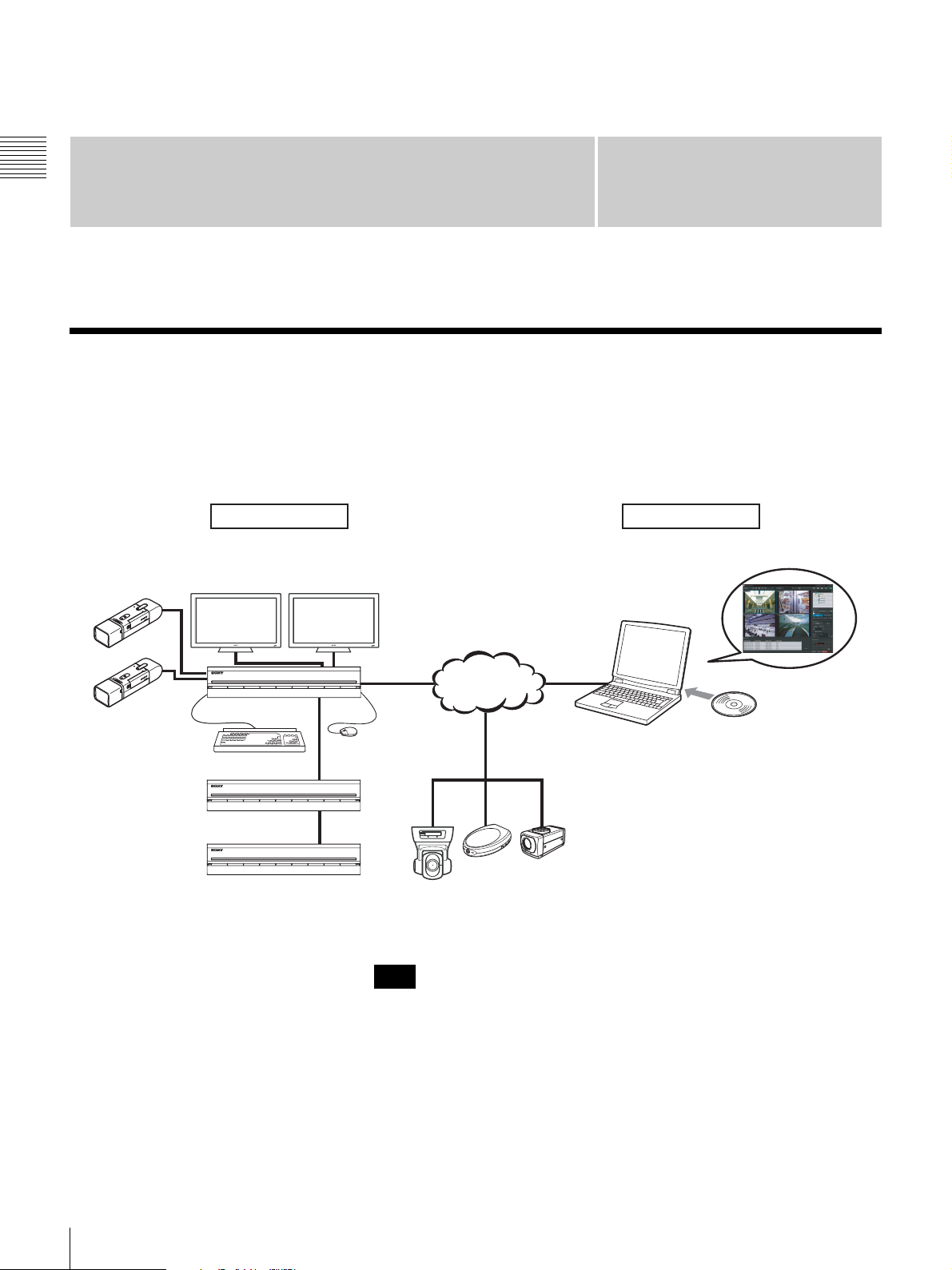
Overview
The NSR series is a hard disk recording server for network cameras. The NSR allows you to monitor and record network
camera images (JPEG or MPEG-4). It also allows you to play back the recorded images and search through it, making the
NSR a truly versatile monitoring system.
Machine room Surveillance room
Analog cameras
1)
NSR-1000 Series
NSRE-S200
NSRE-S200
Monitor
Keyborad
RealShot Manager Advanced
Client is used for surveillance
and configuration.
Network
Mouse
Surveillance cameras
1) The NSR-1050H is standard equipped with an NSBK-A16 analog encoder board,
but the NSR-1200/1100 requires an optional NSBK-A16 expansion.
Note
With two monitors connected to the NSR, you can perform settings and
monitoring operations on monitor 1 and hot spot monitoring on monitor 2.
Windows PC
Installing
RealShot Manager Advanced
Client Softwate
6
Overview

Control compatible cameras from remote
locations
You can pan, tilt, and perform zoom operations of
compatible cameras.
Compatible with analog cameras
You can monitor and record images from analog cameras
by connecting them directly to the unit
1) The NSR-1200/1100 requires an NSBK-A16 (optional)
expansion, while the NSR-1050H has a built-in connector.
1)
.
High reliability
The NSR-1200 supports RAID 5
1)
and peforms with high
reliability. The system can continue functioning even if
one of the hard disks develops a malfunction. Similarly,
because the system software and settings are stored on the
internal flash memory of the NSR, if the system software
develops a malfunction, lightning-quick restoration of the
system is possible. The NSR also supports uninterruptible
power supplies (UPS)
2)
, making them extremely reliable
systems.
Chapter 1 Introduction
Large-capacity hard disks allow recording for
long periods of time
Equipped with large-capacity hard disks, the unit is
capable recording high-quality images for extended
periods of time. For reference examples, see “Reference
Data for Installation” (page 11).
Slim type (2U), space-saving 19-inch rack
mounting model
With the optional rack mounting kit (sold separately), the
unit can be installed in a standard universal pitch EIA 19inch rack.
High-resolution up to 480 fps (VGA, JPEG)
recording
The NSR-1200 can support up to 64 cameras, the NSR1100 can support up to 32 cameras, and the NSR-1050H
can support up to 20 cameras. The NSR-1200 records
images at a total frame rate of 480 fps
NSR-1100, 120 fps with the NSR-1050H) in VGA
resolution (640 × 480 pixels)
2)
and JPEG image format (1
1)
(240 fps with the
frame about 31 KB) for a crisp image quality.
1) Maximum frame rate when 16 cameras are connected to the
recorder. Each camera has a frame rate of approximately 30
fps. This frame rate may become less because of
fragmentation on the internal hard disks. Values are based on
Sony measurements. These values are not guaranteed, as
performance may change due to the user’s operating
environment.
2) In QuadVGA resolution (1,280 × 960), the frame rate is 1/4
that of VGA resolution.
1) RAID 5 is a system for dividing and storing data and parity
(error correcting codes) onto more than one hard disk drive.
Although this system allows continued operation should one
of the hard disks malfunction, it does not guarantee restoration
of lost data. In addition, due to high internal processing loads
during reconstruction after you replace the malfunctioned
hard disk, the unit may not be able to record images at the
configured recording rate while reconstruction is in progress.
2) If the power turns off suddenly during operation, the data may
be corrupted. In particular, when using the unit together with
an NSRE-S200 or other expansion storage, use a UPS.
Other features
• You can display the images from up to 64 cameras
(8 × 8 images) on one screen.
• The NSR is capable of manual, scheduled, and alarm
recording, among others.
• The NSR is equipped with a motion detection function
1)
(Video Motion Detection (Recorder)).
• Run searches for recorded images by camera name, date,
alarm, and other methods.
• Create privacy zones by using the dynamic masking
functions
2)
. Dynamic masking covers pan, tilt, and
zoom.
• Precise alarm processing is made possible by performing
the various types of filtering
3)
that use the image
processing results sent from the camera in the form of
object information metadata. Because filtering can be
applied to metadata that has already been recorded, you
can also search for areas of interest after recording is
finished.
• Audio recording and playback
4)
are also supported from
compatible cameras.
1) Some functions are limited depending on the number of
cameras connected.
2) Some functions are limited depending on which camera
models are connected.
3) To perform motion detection and object detection using
metadata, a camera that supports motion detection by
metadata is required. The use of metadata is supported for up
to 32 cameras.
4) Optional audio amplifiers or speakers are required.
Overview
7
Features and Functions
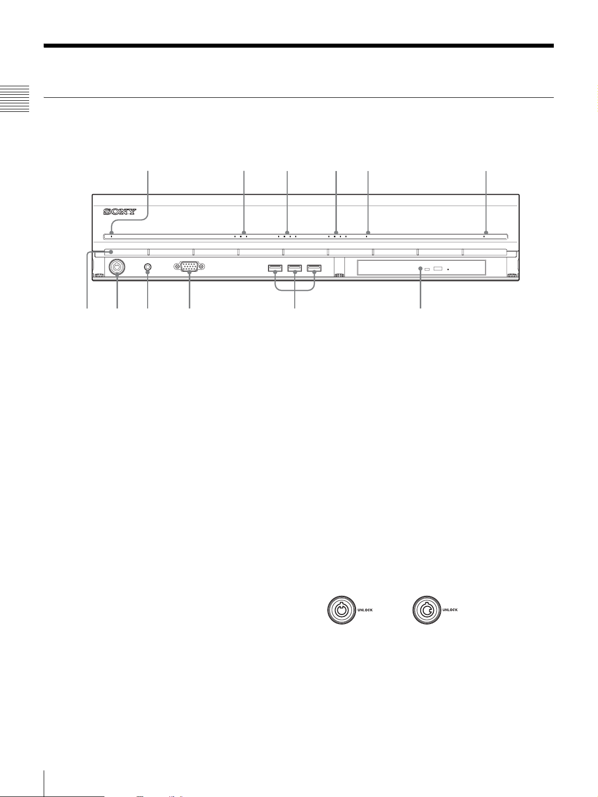
Front (When the Cover is Opened)
Chapter 1 Introduction
NSR-1200/1100/1050H
12345 6
POWER 1 2 3NETWORK 1 2 3 4HDD 1 2 3 4 ERRORSTATUS REC
708qa 9qs
A Power LED
Lights green when the unit is turned on.
Lights amber when it is on standby.
B Network LED (1 to 3)
Lights green when there is activity at the
corresponding LAN connector at the rear of the NSR.
C HDD LED
Blinks green when the internal hard disks are accessed.
Lights amber when an error occurs with a hard disk.
D Status LED (1 to 4)
Lights in sequence (1, 2, 3, 4) when the NSR starts.
When an error occurs, the corresponding status LED
lights together with the error LED, which lights or
blinks to indicate the type of error.
For details, see “STATUS LED” (page 132).
E Error LED
Lights or blinks when an error occurs.
F REC LED
Lights when recording images.
G DVD/CD drive
Use this drive to write data from the NSR hard disks to
DVD and CD.
H USB connector
Use this connector to connect a USB keyboard, USB
mouse, or USB flash memory to the NSR.
I Monitor connector 1
Use this connector to connect a monitor.
Monitor connector 1 (and monitor connector 1 on the
rear of the unit) and HDMI monitor connector 1 on the
rear of the unit cannot be used at the same time.
J Power switch
Press this to turn on the unit. (You cannot turn off the
unit with this switch.)
K Lock
Use this in conjunction with the supplied front panel
key to lock the front bezel. When the front bezel is
locked, you cannot pull out the front bezel. Also, do
not lock the front bezel when the front bezel is pulled
out. You can distinguish the locked position from the
unlocked position by looking at the lock, as illustrated
below.
The front bezel is
locked
The front bezel is
unlocked
L Vent holes
These openings allow air to flow from the front of the
NSR to the rear.
Do not block the vent holes, allow dust to accumulate
in the inner mesh of the vent holes, or obstruct the
airflow in any way. Obstructing the airflow allows
heat to build up inside the NSR and may result in fire
or damage.
8
Features and Functions
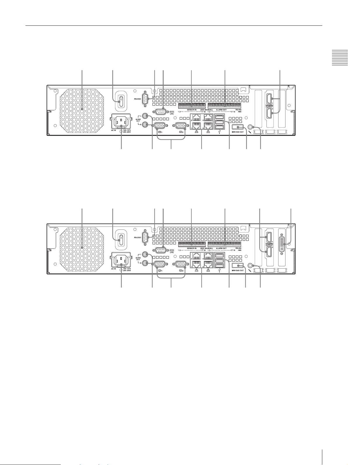
Rear
8
8q
q
90q
q
NSR-1200/1100
NSR-1050H
2316547
Chapter 1 Introduction
9qs 0qaqdqf
2316547qg
f
A Fan
Take care not to obstruct the fan grille. If the grille is
obstructed, heat may build up in the unit, leading to
damage and/or fire.
B Power switch
Press the switch in the 1 position to turn on the unit.
C RS-232C Connector
Use this connector to control analog cameras.
This connector cannot be used at the same time as the
RS-422/485 connector (four rightmost pins on F
alarm output connector).
D UPS connector (RS-232C)
Use this connector to connect the control line of the
uninterruptible power supply (UPS).
d
s
E Sensor input connector
F Alarm output connector
a
Additional configuration is necessary to perform
automatic shutdown with the UPS. Select [Enable] in
the UPS screen of the Setup Menu, and configure the
protocol according to the UPS in use. For details, see
“Setting Items of UPS Screen” (page 19).
Use this connector to connect the sensor input lines.
For connection details and wiring diagrams for sensor
inputs, see “I/O Port” (page 130).
Use this connector to connect the alarm output lines.
For connection details and a wiring diagram for alarm
output, see “I/O Port” (page 130).
Features and Functions
9

G HDMI monitor connectors (1 and 2)
Use these connectors to connect monitors that support
HDMI input.
HDMI monitor connector 1 and L monitor connector
1 (and monitor connector 1 on the front of the unit)
Chapter 1 Introduction
cannot be used at the same time, while HDMI monitor
connector 2 and L monitor connector 2 cannot be
used at the same time.
H Audio input connector (Used for future expansion)
Use this connector to input audio from a peripheral
audio device, such as a microphone.
Plug-In Power microphones are supported.
I Mini-SAS output connector
Use this connector to connect the mini-SAS cable used
for connecting an NSRE-S200.
The NSRE-S200 is an optional expansion storage unit.
J USB connector
Use this connector to connect a USB keyboard, USB
mouse, or USB flash memory to the NSR.
K LAN connectors (1 to 4)
Use these connectors to connect 10 Base-T, 100 BaseTX, or 1000 Base-T network cables.
LAN1: Network cameras
LAN2: Remote Clients
LAN3: Used for future expansion
LAN4: Used for future expansion
L Monitor connectors (1 and 2)
Use these connectors to connect a monitor.
Monitor connector 1 (and monitor connector 1 on the
front of the unit) and H HDMI monitor connector 1
cannot be used at the same time, while monitor
connector 2 and H HDMI monitor connector 2 cannot
be used at the same time.
M Audio output connectors (L and R)
Use these connectors to output audio to a peripheral
audio device.
N Power supply connector
Use this connector to connect the power cord.
System Requirements
The hardware required in order to use this recorder are as
follows.
• Sony Network cameras
Contact your dealer for details about compatible Sony
network cameras.
• Monitor
• USB keyboard
•USB mouse
• USB remote controller
•Network switch
• 1000Base-T/100Base-TX/10Base-T cable
• USB memory device
1) This unit supports HDMI-compatible devices and computer
displays that support RGB input.
The following resolutions can be specified.
- Full High-Definition (1,920 × 1,080)
- WUXGA (1,920 × 1,200)
- Full Wide XGA (1,360 × 768)
- UXGA (1,600 × 1,200)
- SXGA (1,280 × 1,024)
- XGA (1,024 × 768)
2) Use a USB keyboard with a cable. However, keys other than
the standard may not function. Wireless or infrared USB
keyboards may also not function properly.
3) Use a USB mouse with a cable. However, three-button or
wheel mice may not function properly. Wireless or infrared
USB mice may also not function properly.
4) You can use a remote controller to control pan, tilt, and zoom
operations for cameras.
- This unit supports IP Desktop USB controllers from CH
5) Required when backing up system information such as logs.
- This unit supports standard USB 2.0 Mass Storage devices.
Note
When using displays that support both HDMI and RGB
input, we recommend using RGB input.
1)
2)
3)
4)
5)
Products. Other remote controllers are not supported.
Depending on the type of USB 2.0 Mass Storage device,
however, errors may occur when writing data to the device.
If errors occur when writing data, use a USB memory
device of a different type.
O Analog camera cable input connector
Use this connector to connect analog cameras via the
analog camera input cable.
The NSR-1050H is standard equipped with this
connector, but the NSR-1200/1100 requires an NSBKA16 (optional) expansion.
10
System Requirements

Reference Data for Installation
Current Consumption and Inrush Current
Model AC input
voltage
NSR-1200
NSR-1100
NSR-1050H
NSRE-S200
100 V 2.66 A
220 V 1.14 A
100 V 1.84 A
220 V 0.79 A
100 V 1.75 A
220 V 0.76 A
100 V 0.79 A
220 V 0.34 A
Full loading Inrush
current
13 A
Recording Duration Guide
Codec
Server Expansion
NSR-1050H
NSR-1100
NSR-1200
NSR-1200
Server Expansion
NSR-1050H
NSR-1100
NSR-1200
NSR-1200
storage
0 units 8 MPEG4
0 units 16 MPEG4
0 units 16 MPEG4
7 units 16 MPEG4
storage
0 units 4 JPEG
0 units 4 JPEG
0 units 16 JPEG
7 units 16 JPEG
Number of cameras
Number
of
cameras
(size)
(VGA)
(VGA)
(VGA)
(VGA)
Codec
(size)
(VGA)
(VGA)
(VGA)
(VGA)
Number
of days
10 512 kbps 10.00 fps
10 512 kbps 10.00 fps
16 512 kbps 10.00 fps
60 1,024 kbps 20.00 fps
Number
of days
4 Level 5 10.00 fps
10 Level 5 8.00 fps
30 Level 5 1.00 fps
30 Level 5 9.00 fps
Bitrate Frame
Quality Frame
rate
rate
Chapter 1 Introduction
mini-SAS cable (accessory of NSRE-S200):
SONY Part No. 9-885-130-46
Storage Capacity for Recorded Data
The storage capacities for recorded data on the NSR-1200/
1100/1050H and optional expansion storage are as
follows.
Model Storage capacity for recorded data
NSR-1200 1,366 GB
NSR-1100 886 GB
NSR-1050H 443 GB
NSRE-S200 1,396 GB
* Data capacities are approximations based on the following
equation for 1 GB:
1,024 × 1,024 × 1,024 = 1,073,740,000 bytes
Number of Cameras
Maximum number of cameras
Model Maximum number of cameras
NSR-1200 64
NSR-1100 32
NSR-1050H 20
Maximum number of analog cameras (included in
total number of cameras)
Model Maximum number of analog cameras
NSR-1200 16 (with optional NSBK-A16)
NSR-1100 16 (with optional NSBK-A16)
NSR-1050H 16
Maximum number of megapixel cameras
(included in total number of cameras)
Model Maximum number of cameras
NSR-1200 8
NSR-1100 4
NSR-1050H 4
Ex.) NSR-1050H (maximum number of cameras: 20)
IP cameras : 12
IP cameras (megpixel) : 4
Analog cameras : 4
Reference Data for Installation
11

Administration Menu
Chapter 2
Administration Menu
Overview
The Administration Menu allows you to change settings
that were configured with the Setup Wizard when you
turned on the NSR for the first time, and also allows you to
perform configurations and operations related to the
server.
This chapter describes the following configurations and
operations for the Administration Menu.
• “Displaying the Administration Menu” (page 12)
• “Changing Initial Settings with the Setup Menu”
(page 13)
• “Configuring Settings Related to Servers” (page 20)
• “Installing Patch Files” (page 21)
• “Saving and Restoring Configuration Data” (page 22)
• “Exporting System Information” (page 24)
Chapter
2
Displaying the Administration Menu
1
Enter the user name and password in the logon screen,
and click [Administration Menu].
Note
For details on restart and shutdown procedures, see
Chapter 3 “Shutting Down and Restarting the NSR”
(page 30).
Note
If you are already logged on to the NSR, you can
display the logon screen by clicking at the top
right of the Main screen and logging off from the
dialog box that appears.
The Administration Menu screen appears.
12
Overview
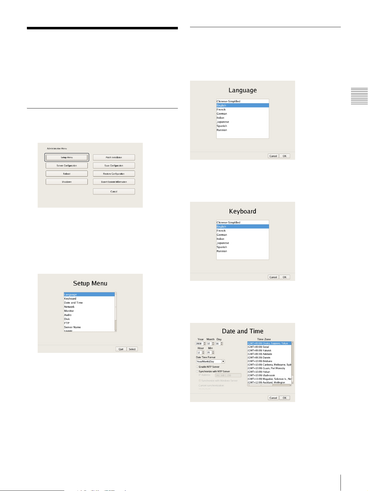
Changing Initial Settings
Details on Setting Items
with the Setup Menu
Use the Setup Menu to change settings that were
configured with the Setup Wizard when you turned on the
NSR for the first time.
Displaying Setup Menu
1
Click [Setup Menu] in the Administration Menu.
The menu items of the Administration Menu differ
depending on the server and clients.
Setting Items of Language Screen
Select the language to display on the screens, and click
[OK].
Chapter 2
Administration Menu
Setting Items of Keyboard Screen
Select the language of the USB keyboard connected to
NSR, and click [OK].
The Setup Menu appears.
2
Select the item you want to configure, and click
[Select].
The screen corresponding to the item appears.
Setting Items of Date and Time Screen
Configure the date and time of the equipment, and click
[OK].
Year/Month/Day
Enter the date.
Hour/Min
Enter the time.
Changing Initial Settings with the Setup Menu
13
Date Format
Select the format for the date and time.
Enable NTP Server
Select the check box to enable the NTP server of NSR.
Synchronize with NTP Server
Select the check box to obtain the current time from
another NTP server.
IP Address
Chapter 2
Enter the IP address of the NTP server from which to
obtain the information.
Synchronize with Windows Server
Administration Menu
When a Windows server is used as the NTP server,
select the check box when synchronization of the time
is not possible.
Selecting this check box forces the time to be
synchronized with the Windows NTP server.
Current Synchronization
This displays the IP address of the NTP server from
which the current information is being obtained.
Time Zone
Select the region to configure the date and time.
Note
There is no setting for enabling or disabling daylight
saving time. If you select a time zone in which daylight
saving time is observed, the clock is adjusted
automatically for daylight saving time.
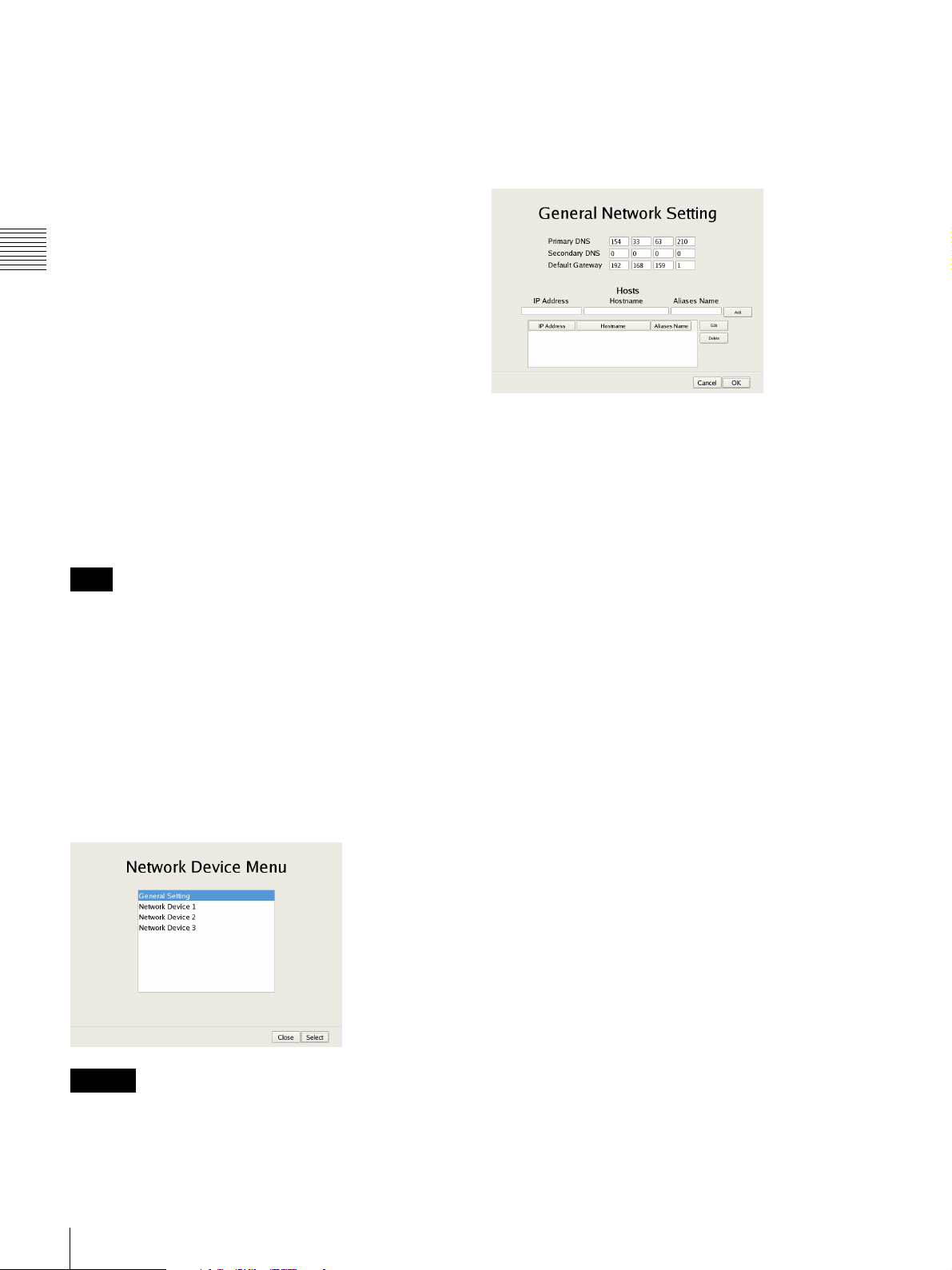
Setting Items of Network Device Menu
Screen
The network settings consist of “General Network” for
setting general settings, and “Network Device 1 to 3” for
setting LAN ports.
Select the network you want to configure, and click [OK].
LAN3: External storage device (Such a device may not be
supported depending on the software version. Consult
the place of purchase.)
xSetting Items of General Network Screen
Configure each item, and click [OK].
Primary DNS
Enter the IP address for the primary DNS (Domain Name
Server).
Do not enter this if there is no primary DNS, or if it is not
required.
Secondary DNS
Enter the IP address for the secondary DNS. Do not enter
this if there is no secondary DNS, or if it is not required.
Default Gateway
Enter the IP address for the default gateway. Do not enter
this is if there is only a local network or there is no need to
connect to another network.
Hosts
If there is a special need to register a host name for the host
file, enter a combination of the IP address and host name,
and click [Add] to add the host to the list.
Caution
Connect the following devices to the LAN ports.
LAN1: Network camera
LAN2: Remote client
14
Changing Initial Settings with the Setup Menu
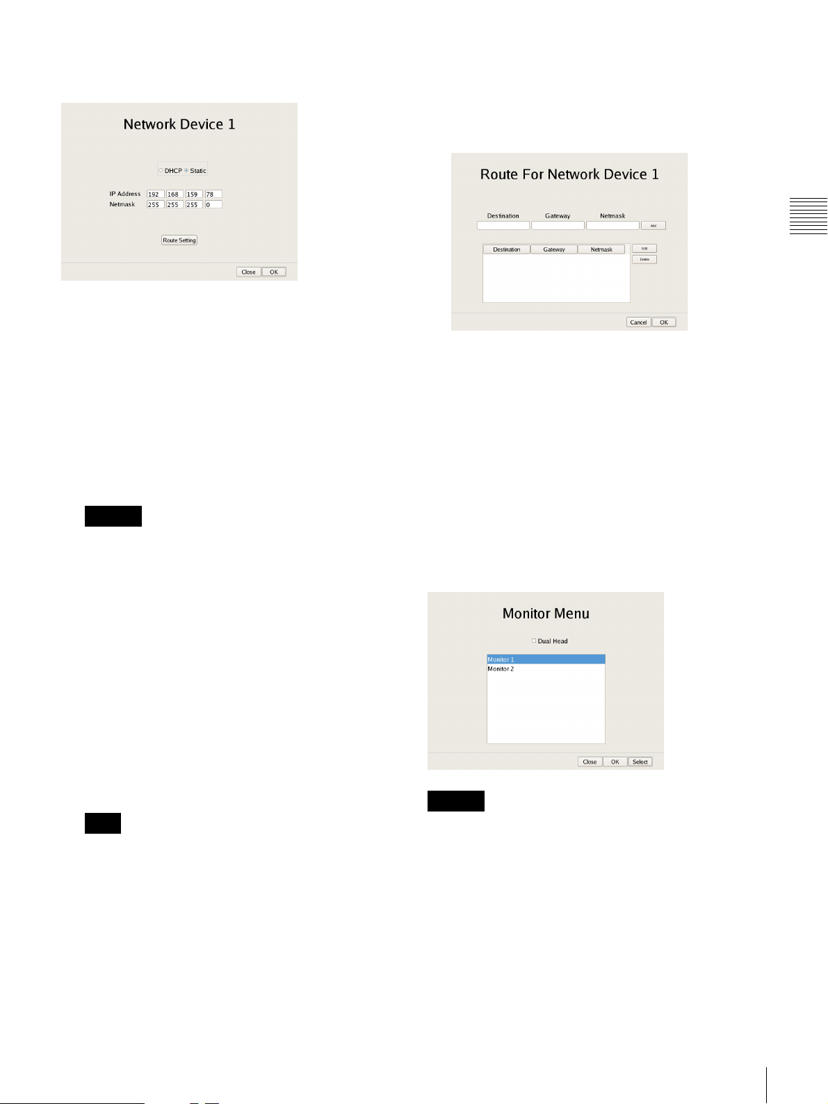
xSetting Items of Network Device 1 to 3
Configure each item, and click [OK].
Route Setting
Click this when you need to configure the route to
another network.
Configure the settings as follows on the Route For
Network Device 1 screen that appears.
Chapter 2
Configure the settings as follows in accordance with your
environment.
To use a DHCP to obtain the address setting automatically:
Select [DHCP].
To configure the address setting manually:
1 Click [Static].
2 Enter the following address.
IP Address
Enter the IP address.
Caution
• Before you enter the IP address, make sure there is
no machine that uses the same value on the same
network. Even if a machine that uses the same value
does exist, an error message will not be displayed.
However, be careful because more than one machine
using the same value will result in incorrect
operation.
• Even if you set an IP address that is prohibited under
the IP address assignment rules, it will not be
reflected in the system.
Example: 224.0.0.0 to 255.255.255.255
0.0.0.0
127.0.0.1, etc.
Administration Menu
1 Enter the address, gateway, and netmask of the
other network to which to connect, and click [Add]
to add the network to the list.
For details, contact the administrator of the network
to which you will connect.
2 Click [OK].
Setting Items of Monitor Menu Screen
Select the monitor you want to configure, and click
[Select].
When you want to use two monitors connected to NSR,
selecting the [Dual Head] check box allows you to
configure the second monitor.
Netmask
Enter the subnet mask.
Note
The default values for a network device are shown
below.
IP Address: 192.168.[0/1/2]
Netmask: 255.255.255.0
1)
The setting values for each of the network devices [#1/#2/
#3].
1)
.1
Caution
After you configure the second monitor, the system needs
to be restarted while the second monitor is connected.
Changing Initial Settings with the Setup Menu
15
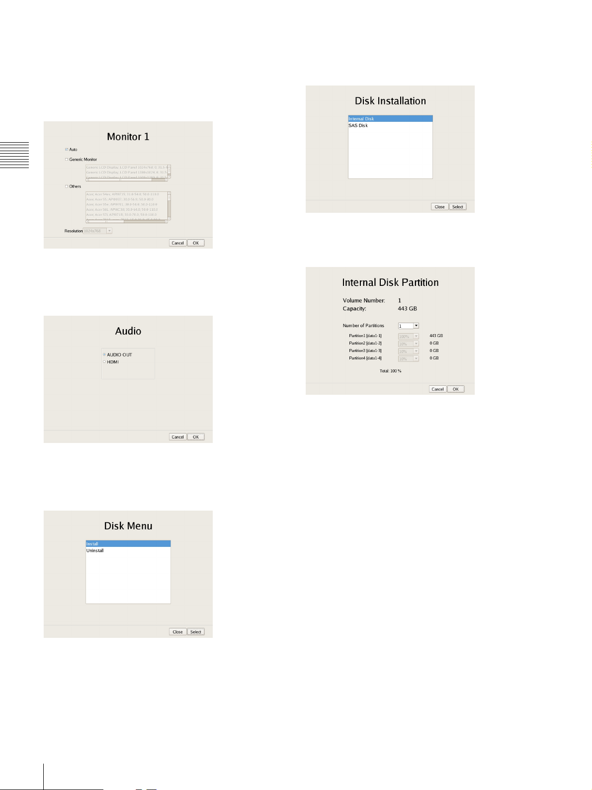
xSetting Items of Monitor 1 to 2
Select the type and resolution of the monitor connected to
this equipment, and click [OK].
If you select [Auto], the type and resolution of the
connected monitor is detected and the setting is configured
automatically.
Chapter 2
Administration Menu
Setting Items of Audio Screen
Select the audio connector you want to use, and click
[OK].
xSetting Items of Disk Installation Screen
Select the hard disk drive you want to operate, and click
[Select].
xSetting Items of Internal Disk Partition Screen
Configure the partitions of the internal hard disk drive, and
click [OK].
Setting Items of Disk Menu Screen
Select the operation for the hard disk drive, and click
[Select].
Capacity
This displays the capacity of the internal hard disk drive.
Number of Partitions
Select the number of partitions.
Partition1 [data1-1]
Select the size to allocate each partition as a percentage.
16
Changing Initial Settings with the Setup Menu
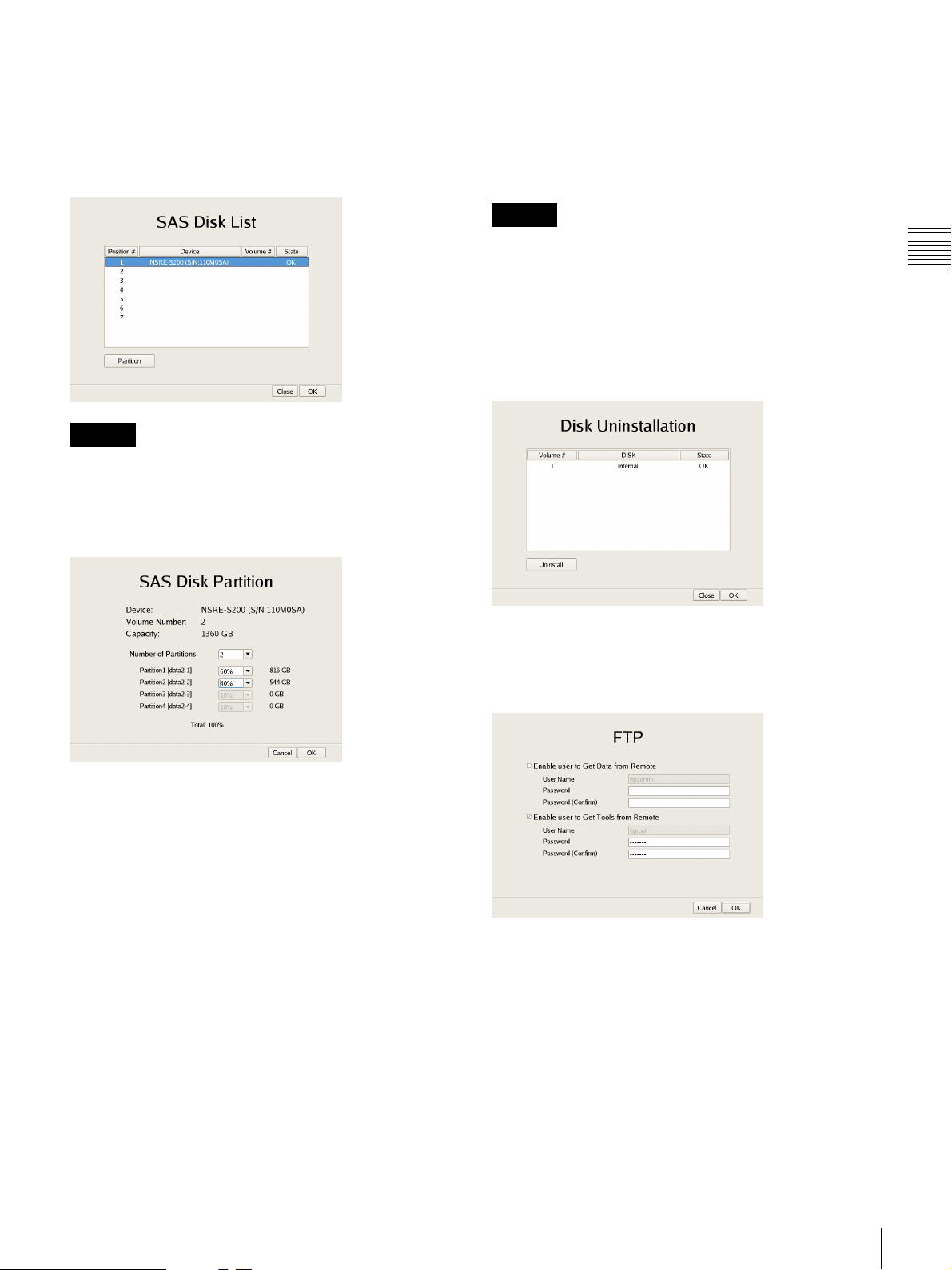
xSetting Items of SAS Disk List Screen
Select the NSRE-S200 for which you want to configure the
partition settings, and click [Partition]. When you have
finished configuring the settings, click [OK].
(This screen is only displayed when an NSRE-S200 is
connected.)
Caution
When an NSRE-S200 is connected, use a UPS.
xSetting Items of SAS Disk Partition Screen
Configure the partitions of the internal hard disk drive of
NSRE-S200, and click [OK].
xSetting Items of Disk Uninstallation Screen
Select the hard disk drive you want to delete, and click
[Uninstall]. When you have finished configuring the
settings, click [OK].
If you uninstall a hard disk, all of the data on the hard disk
will be deleted.
Caution
In particular, if you uninstall a hard disk drive that has
multiple partitions, multiple logical volumes registered on
the [Storage] tab of the Server Configuration screen will be
deleted automatically. Before you uninstall a hard disk,
check the [Storage] tab to confirm whether it is alright to
delete the registered storage.
For details on the [Storage] tab of servers, refer to
“Configuring Settings Related to Storage” (page 70).
Chapter 2
Administration Menu
Capacity
This displays the capacity of the internal hard disk drive.
Number of Partitions
Select the number of partitions.
Partition1 [data1-1]
Select the size to allocate each partition as a percentage.
Setting Items of FTP Screen
Configure each of the items when you want to enable the
FTP server, and click [OK].
Enable user to Get Data from Remote
Select the check box to enable remote client downloading
of recorded data using FTP.
If you select this check box, set the password.
User Name
This displays the user name. The user name is
“ftpupdate.”
It cannot be changed.
Password
Enter the password.
Changing Initial Settings with the Setup Menu
17
Enable user to Get Tools from Remote
Select the check box to enable remote client downloading
of tools, operating manuals, and other documents using
FTP.
This is enabled under default settings.
User Name
This displays the user name. The user name is
“ftptool.”
It cannot be changed.
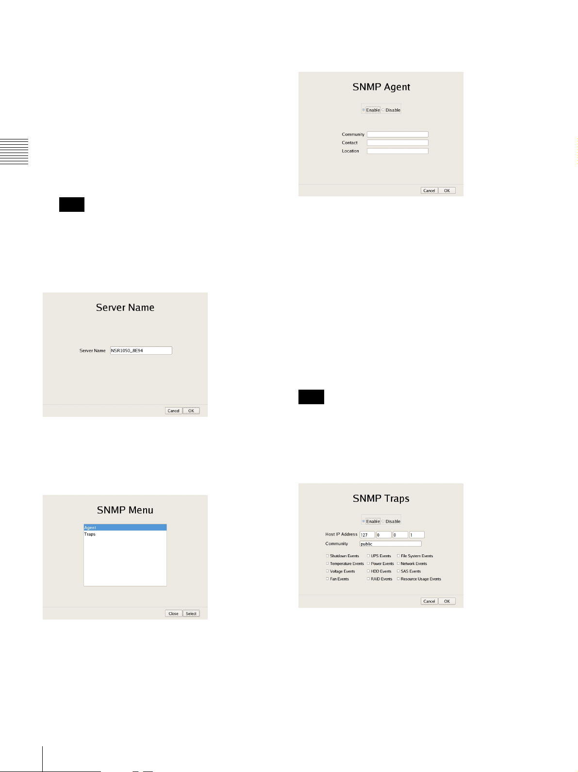
xSetting Items of SNMP Agent Screen
Configure each item, and click [OK].
Chapter 2
Password
Enter the password. The default password is “ftptool.”
Administration Menu
Note
The user name and default password are both
“ftptool.”
Setting Items of Server Name Screen
Enter the server name of NSR, and click [OK].
Setting Items of SNMP Menu Screen
Select [Agent] when configuring an SNMP community,
and [Traps] when configuring an SNMP trap, and click
[OK].
Enable
Select this to enable the SNMP agent function.
Disable
Select this to disable the SNMP agent function.
Community
Enter the SNMP community name.
Contact
Enter the contact.
Normally, enter the mail address of the system
administrator.
Location
Enter the installation location of NSR.
Note
The MIB-2 object of “System” or “SystemUptime”
indicated with the object ID “.1.3.6.1.2.1.1” or
“.1.3.6.1.2.1.25.1.1” can be obtained.
xSetting Items of SNMP Traps Screen
Configure each item, and click [OK].
18
Changing Initial Settings with the Setup Menu
Enable
Select this to enable the SNMP traps function.
Disable
Select this to disable the SNMP traps function.
Host IP Address
Enter the IP address of the traps host.
Community
Enter the SNMP community name.
Shutdown Events
Notify when the NSR shuts down.
Temperature Events
Notify when the temperature of NSR rises.
Voltage Events
Notify when the voltage is abnormal.
Fan Events
Notify when the fan is abnormal.
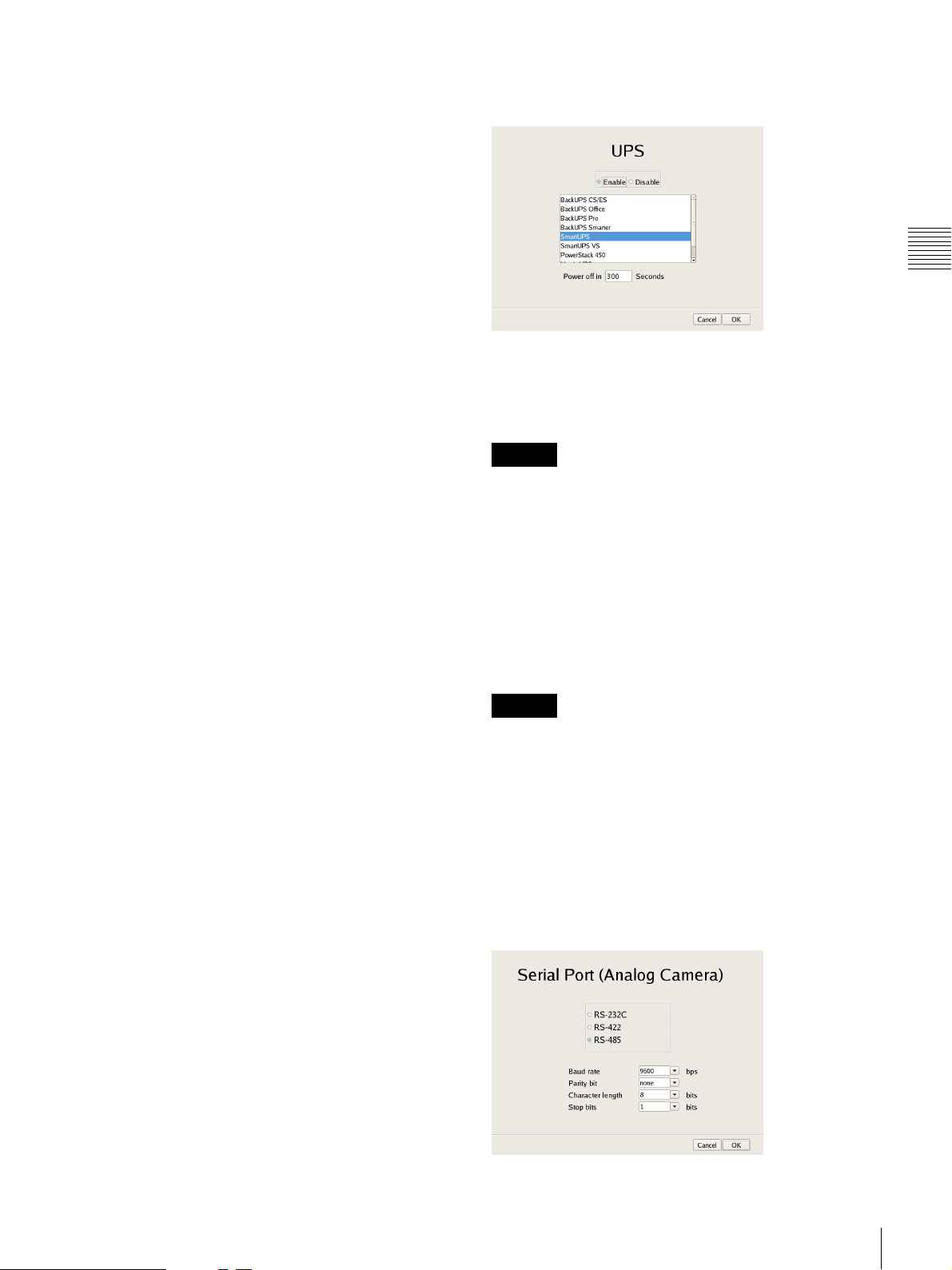
Setting Items of UPS Screen
Configure settings related to UPS, and click [OK].
Chapter 2
UPS Events
If a UPS is connected, notify when the UPS has detected a
power cut, and when the UPS has detected recovery from
the power cut.
Power Events
Notify when a power malfunction occurs.
HDD Events
Notify when a hard disk drive malfunctions.
RAID Events
Notify when a RAID group rebuilds.
File System Event
Notify when a file system malfunction occurs.
Network Events
Notify when a network device malfunction occurs.
Resource Usage Events
Notify when the management domain of the hard disk
drive or percentage of CPU used is abnormally high.
SAS Events
Notify when a connected NSRE-S200 malfunctions.
Administration Menu
Enable
Select this when using a UPS.
If this is selected, select the type of UPS to be used from a
list of UPS.
Caution
If the power turns off suddenly during operation, the data
may be corrupted. In particular, when using the unit
together with an NSRE-S200 or other expansion storage,
use a UPS.
Disable
Select this when not using a UPS.
Power off in XXX Seconds
Enter the time from when a power cut is detected until
shutdown.
Caution
For details on automatic startup after power is restored,
contact your dealer.
Setting Items of Serial Port (Analog
Camera) Screen
Configure settings related to the analog camera
connection.
Configure each item, and click [OK].
(This screen appears when an NSR-1050H or NSBK-A16
(option) is connected.)
Changing Initial Settings with the Setup Menu
19
Serial standard (RS-485, RS-422, RS-232C)
Select the serial standard for connecting to the analog
camera you want to control.
Baud rate
Select the communication baud rate.
Configuring Settings Related to Servers
Parity bit
Select the parity bit.
Character length
Select the character length.
Chapter 2
Stop bits
Select the stop bits.
Administration Menu
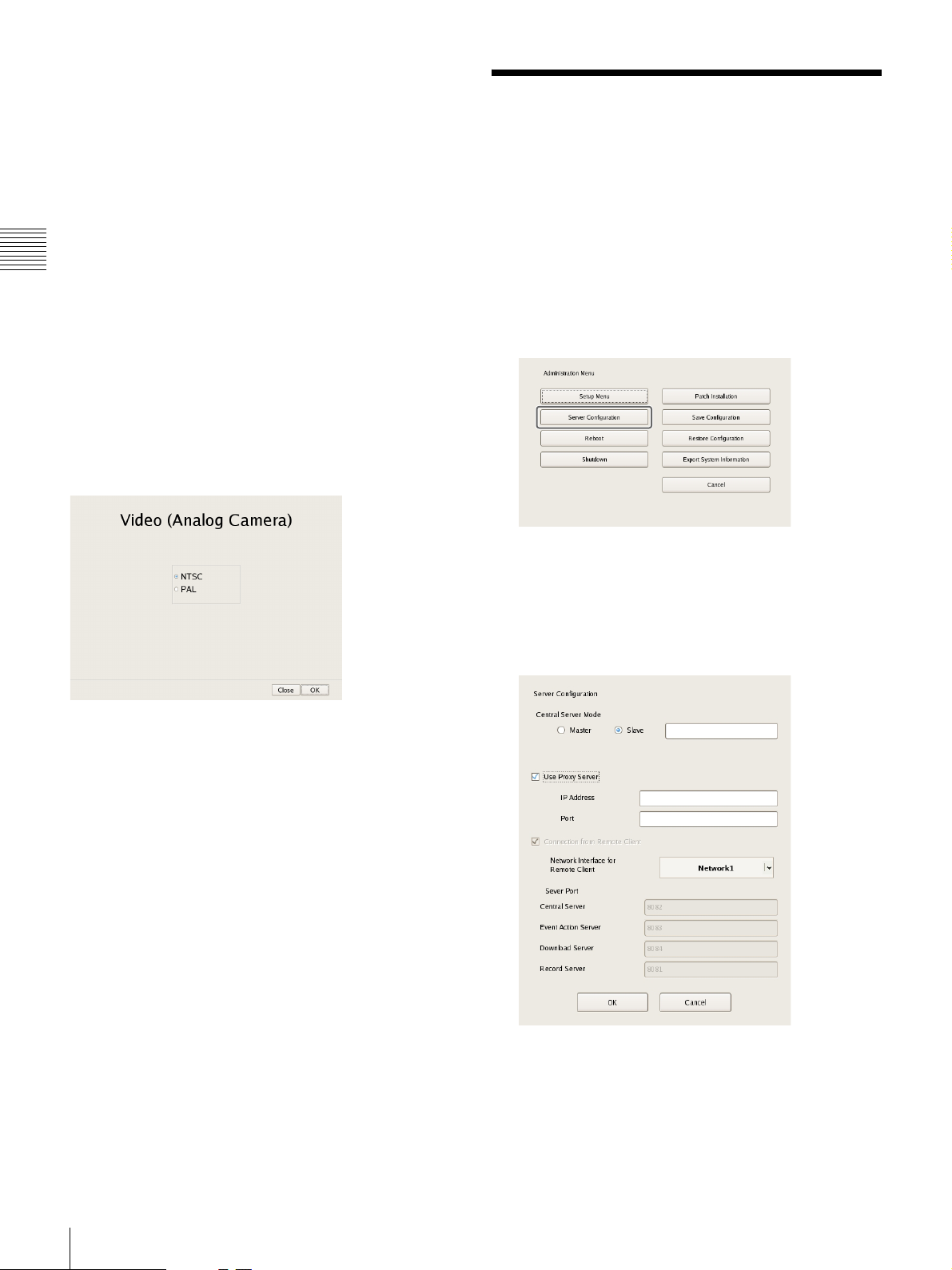
Setting Items of Video (Analog Camera)
Screen
Select the video format for the analog camera to be
connected, and click [OK].
(This screen appears when an NSR-1050H or NSBK-A16
(option) is connected.)
Configure these settings when, for example, you want to
change the network settings to match the network
environment of the users, or you want to centralize user
administration when using multiple NSR and RealShot
Manager Advanced together.
1
Click [Server Configuration] in the Administration
Menu.
The menu items of the Administration Menu differ
depending on the server and clients.
The Server Configuration screen appears.
2
Configure each item, and click [OK].
20
Configuring Settings Related to Servers
Central Server Mode
Set this if you want to manage multiple NSRs and
RealShot Manager Advanced Server as one system
or you want to connect from RealShot Manager Client.
You can set one master server for uniformly managing
users in the system, and multiple slave servers.
1) This is for when you want to perform common user
management with multiple servers, or when you want to
connect from RealShot Manager Client.
Select [Master] or [Slave].
If you select [Slave], enter the master server address to
which to connect.
If a server is changed from master to slave, the user
information that was configured locally is discarded
and the user information of the master is used.
If you want to change this setting, basically change it
immediately after installation.
If you change this setting, restart the system.
Use Proxy Server
Select the check box when using a proxy server for
connecting to the slave servers and master server of the
central server.
1)
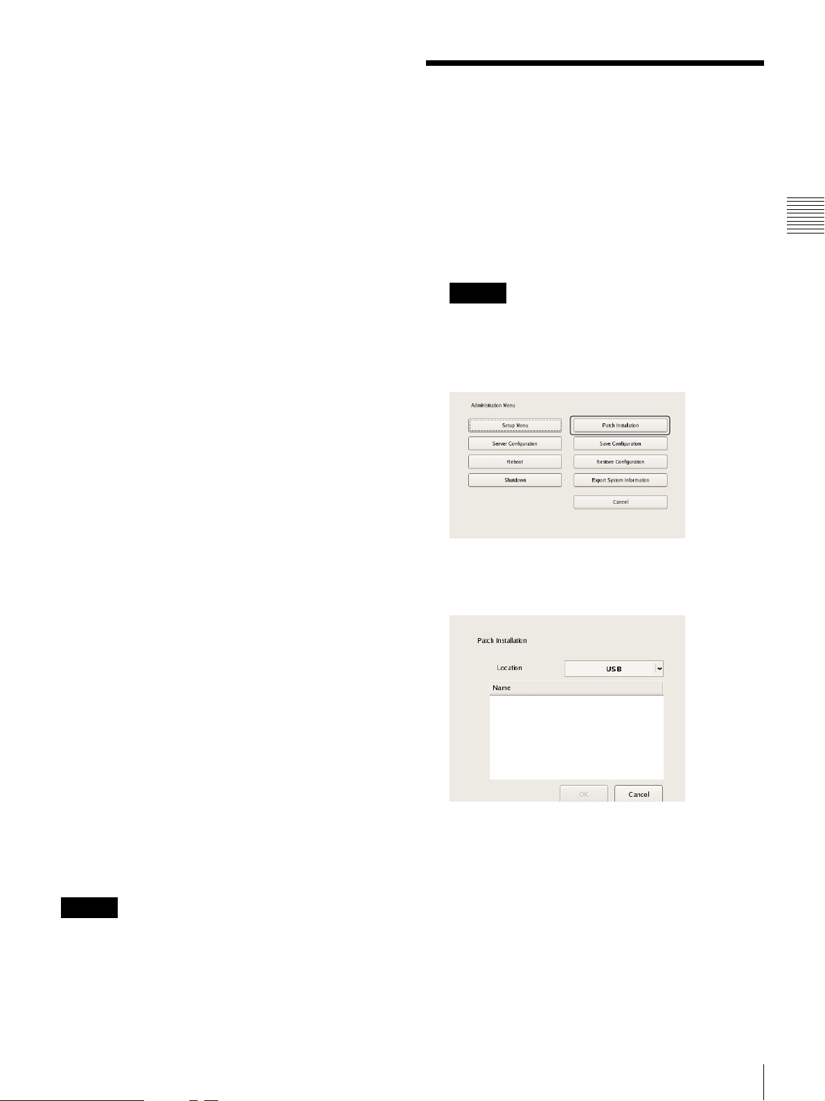
Installing Patch Files
,
You can install patch files distributed by Sony onto the
NSR.
Patch files will be uploaded onto the official Sony Web site
as more NSR-compatible cameras, for example, are added.
1
Download the patch file from the official Sony Web
site, and copy it onto a USB memory device or CD/
DVD.
Caution
Do not change the file name or other aspects of the
patch file.
2
Click [Patch Installation] in the Administration Menu.
Chapter 2
Administration Menu
IP Address
Enter the IP address for the proxy server.
Port
Enter the port number for the proxy server.
Connection from Remote Client
Select the check box to connect from a remote client.
Network Interface for Remote Client
Select the network to use for the connecting with
remote client.
Server Port
Central Server
Display the port number for the central server.
Event Action Server
Display the port number for the event action server.
Download Server
Display the port number for the download server.
Record Server
Display the port number for the record server.
The settings are changed.
The Patch Installation screen appears.
3
Select the media on which the patch file is stored.
A list of patch file names appears.
4
Confirm a patch file name, and click [OK].
A confirmation message appears.
Caution
When the central server mode is changed, a message
appears and the system restarts.
Installing Patch Files
21
5
Confirm the content of the message, and click [Yes].
Chapter 2
Administration Menu
Caution
The NSR will automatically reboot after installation of
certain patch files. A confirmation screen will appear
if reboot is necessary. If you cannot stop your current
operations, select [No] to cancel installation, and
perform installation when rebooting the NSR will not
be a problem.
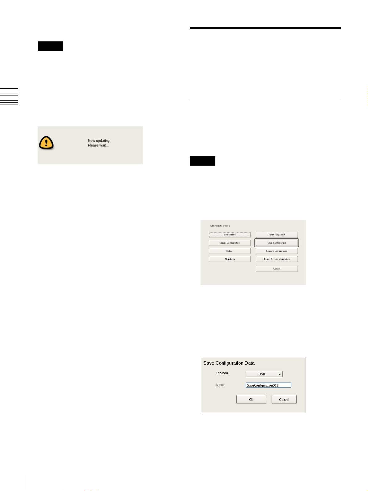
The following screen appears during installation of the
patch file.
When installation is complete, the patch is applied.
Saving and Restoring Configuration Data
You can save the configuration data of NSR to external
media, and restore saved configuration data.
Saving Configuration Data
Generally, the settings configured in the Server
Configuration screen in the Administration Menu of the
logon screen and settings configured in the settings screen
after logging on are stored as configuration data.
Caution
Note that the following information is not saved.
• Recording records
• Log information
1
Click [Save Configuration] in the Administration
Menu.
The menu items of the Administration Menu differ
depending on the server and clients.
The Save Configuration screen appears.
2
Select the media to save the configuration data, enter
the file name for the configuration data, and click
[OK].
A progress bar is displayed during the backing up of
the configuration data, and the configuration data is
saved when the backup is finished.
22
Saving and Restoring Configuration Data
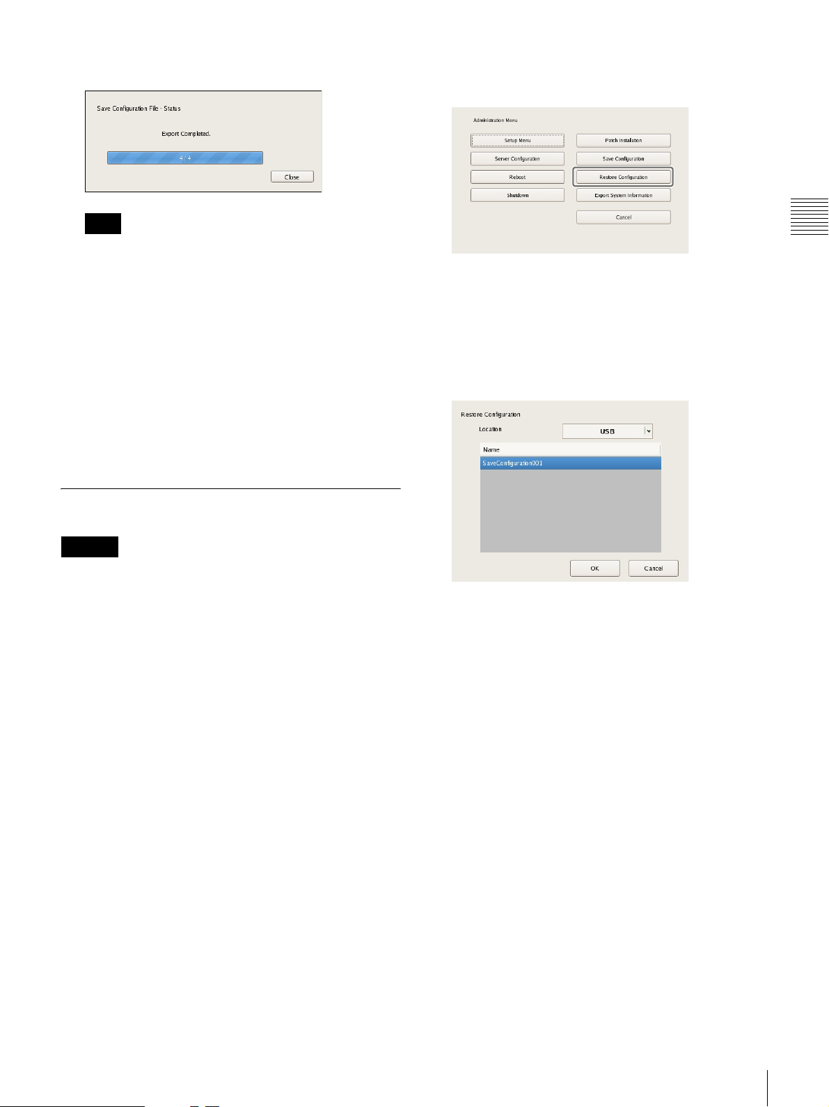
3
Click [Close].
1
Click [Restore Configuration] in the Administration
Menu.
Note
When saving of the configuration data finishes, the
following files are created in the save location.
<Configuration data save name>.item
<Configuration data save name>_db.tar.gz
<Configuration data save name>_img.tar.gz
<Configuration data save name>_os.tar.gz
Example: When the configuration data is saved under
the name “Configuration001,” files with the names
shown below are created.
Configuration001.item
Configuration001_db.tar.gz
Configuration001_img.tar.gz
Configuration001_os.tar.gz
Restoring Configuration Data
Caution
• Note that the following information is not restored.
– Recording records
– System settings such as network settings and time
information (Items of [Setup Menu] (page 13))
– Logs
• The settings of the external storage itself cannot be
restored, so it is necessary to configure them to the same
settings as those at the time of saving.
• The configuration data cannot be restored if the first two
digits of the current version (e.g.: “a.b” of “a.b.c”
separated by “.”) differ from those at the time of saving
or the model differs.
• When the configuration data is restored, the recording
operation performed up until that point is stopped
automatically. If a recording schedule has been
configured, recording resumes automatically after
restoration. If manual recording was performed, it needs
be started again.
The menu items of the Administration Menu differ
depending on the server and clients.
The Restore Configuration screen appears.
2
Select the location where the configuration data is
saved and the configuration data, and click [OK].
A confirmation message appears to notify you that this
operation requires NSR to be restarted.
3
Click [OK].
A confirmation message appears.
4
Click [OK].
A progress bar appears during restoring, NSR restarts
when the process is finished, and the configuration
data is restored.
Chapter 2
Administration Menu
Saving and Restoring Configuration Data
23
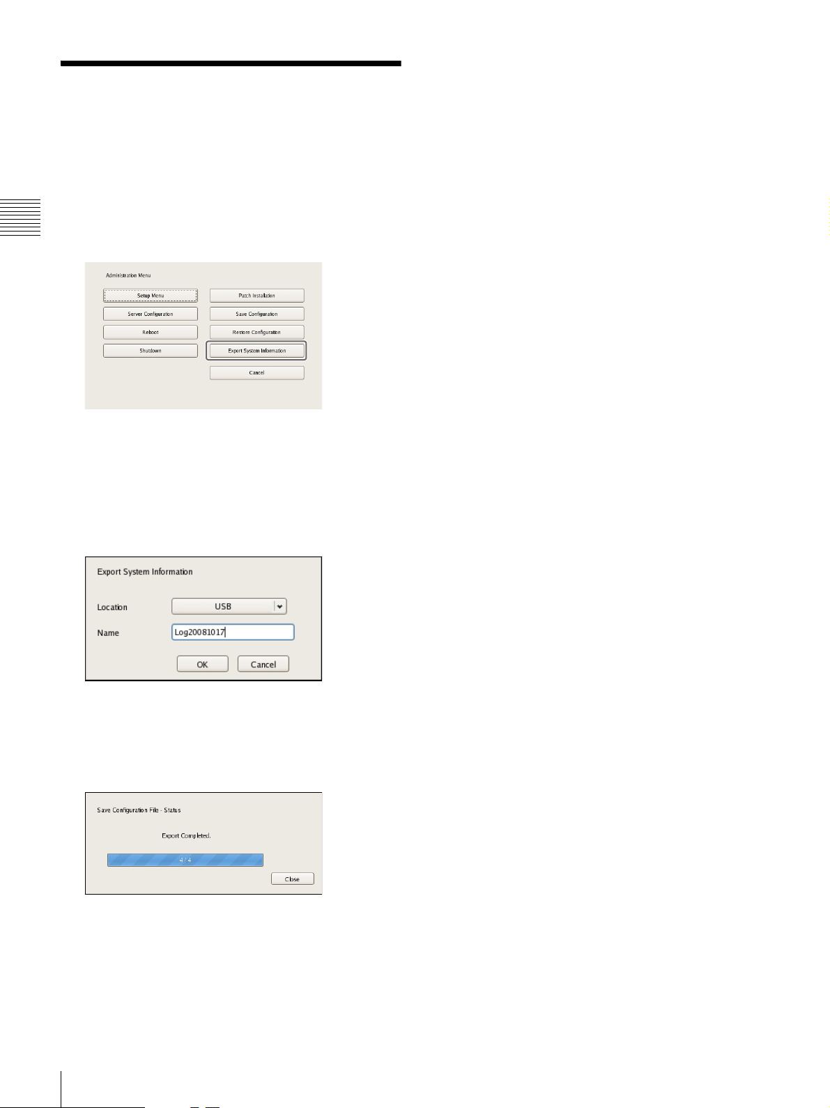
Exporting System Information
You can save NSR system information as files onto
external media.
1
Chapter 2
Administration Menu
Click [Export System Information] in the
Administration Menu.
The items that appear in the Administration Menu vary
depending on the server and client.
The Export System Information screen appears.
2
Select the media on which to save the system
information, enter the file name, and then click [OK].
A progress bar is displayed during exporting of the
system information, and the system information is
saved when exporting is finished.
3
Click [Close].
24
Exporting System Information

Basic Operation
Chapter
3
Overview
This chapter describes how to perform the following basic
operations on the NSR, including logging on, using
various windows, changing the password, and turning off
the unit.
• “Logging On to the NSR” (page 25)
• “Basic Window Operations” (page 27)
• “Changing the Password” (page 29)
• “Logging Off” (page 29)
• “Locking the NSR” (page 30)
• “Shutting Down and Restarting the NSR” (page 30)
• “Viewing Version Information” (page 31)
Note
For details on settings related to devices, schedules, sensor
inputs, and alarm outputs, see Chapter 4 “Application
Settings” (page 32). For details on monitoring and search
for and playing back recorded images, see Chapter 5
“Operation and Control” (page 105).
Logging On to the NSR
Before you can use the NSR, you must first log on.
1
Press the power switch on the front or rear panel of the
NSR to turn it on.
The startup screen appears, and the progress bar for
software startup appears.
Note
The fan noise may be loud for about 2 seconds after
turning on the unit. This is not a malfunction.
Chapter 3 Basic Operation
After startup, the logon screen appears.
Overview
25
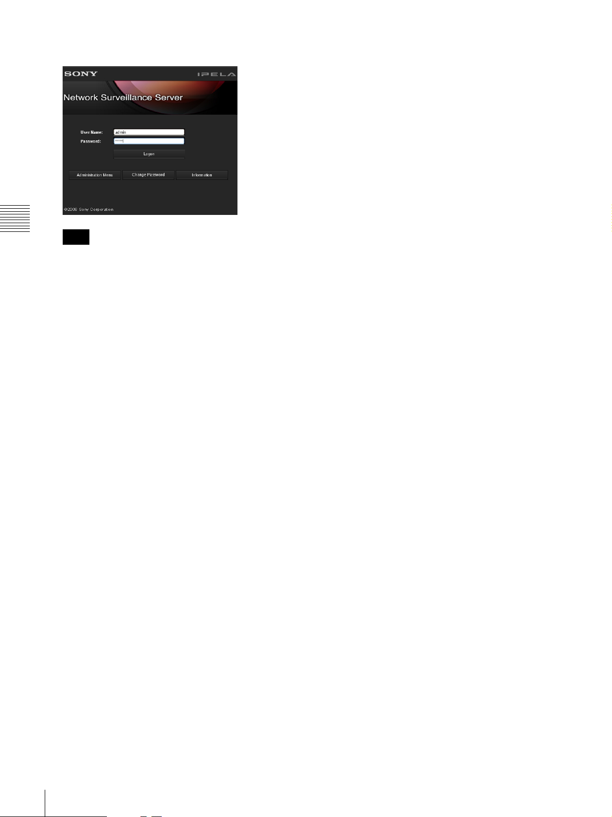
2
Enter the user name and password, and click [Logon].
Chapter 3 Basic Operation
Note
The first time you turn on the NSR, the administrator
is the only user registered on the system. The default
user name for the administrator is as follows.
User name: admin
Password: admin
26
Logging On to the NSR
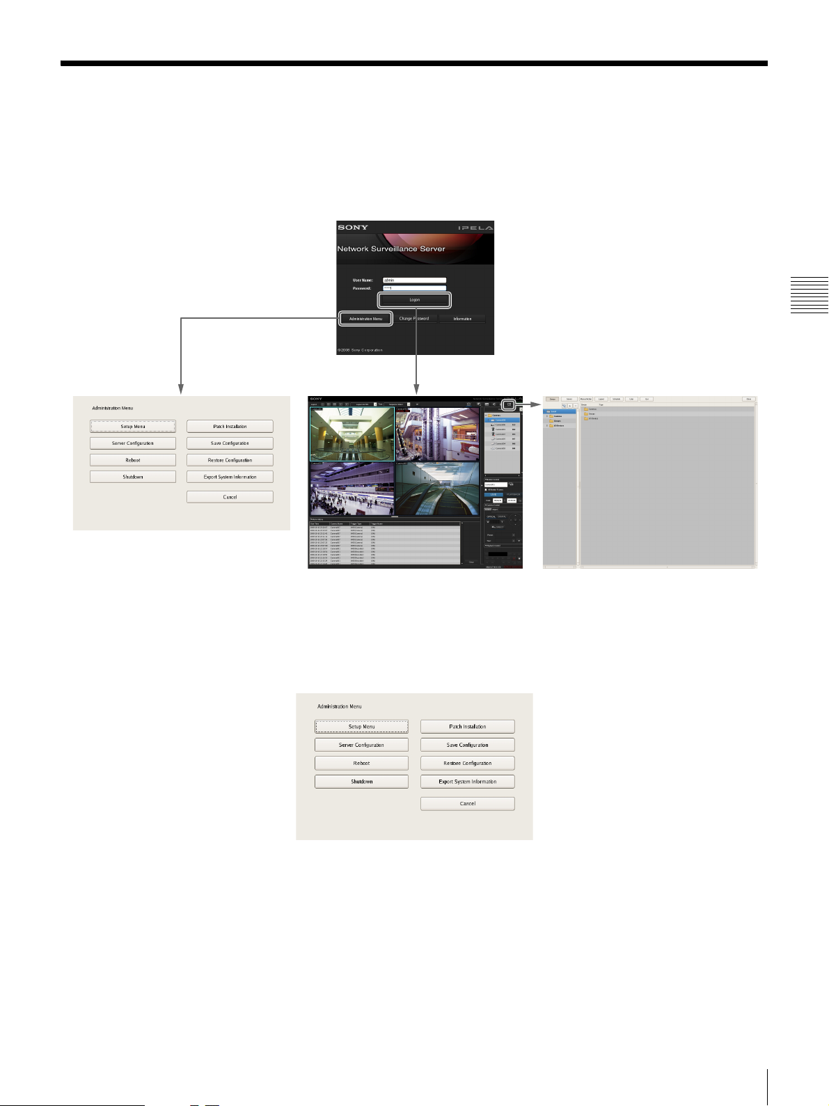
Basic Window Operations
This section provides a brief description of the basic operations for each screen.
The unit includes a Main screen for monitoring images, a configuration screen for configuring various settings, and an
Administration Menu for performing configurations and operations related to the NSR unit.
Logon Screen
Chapter 3 Basic Operation
Administration Menu Main Screen Configuration Screen
Administration Menu
When you click [Administration Menu] in the logon screen, the Administration Menu screen appears. Click each button
to perform various configurations and operations for the NSR unit.
For details on settings that can be configured from the Administration Menu, see Chapter 2 “Administration Menu”
(page 12).
Basic Window Operations
27
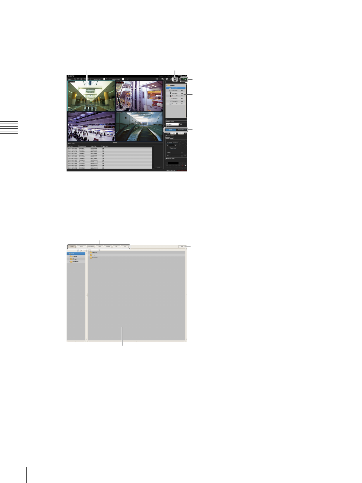
Main screen
In the Main screen, you can monitor live images from each monitor frame, and search for and play back recorded images.
To switch between live image display and playback of recorded images, click the target monitor frame, and then click
[LIVE] or [PLAYBACK] on the right side of the window.
Monitor frame Displays the Configuration screen.
Allows you to log off or restart the NSR.
Select cameras.
Switch between live image display and
Chapter 3 Basic Operation
For details on monitoring and searching for and playing back recorded images, see Chapter 5 “Operation and Control”
(page 105).
playback of recorded images.
Configuration screen
Configure settings that are necessary for operating the NSR, such as camera registration, schedule settings, and user
registration.
For details on setting items and how to configure them, see Chapter 4 “Application Settings” (page 32).
Click the button for the item you want to configure.
Returns to the Main screen.
Setting items appear based on the button you clicked.
28
Basic Window Operations
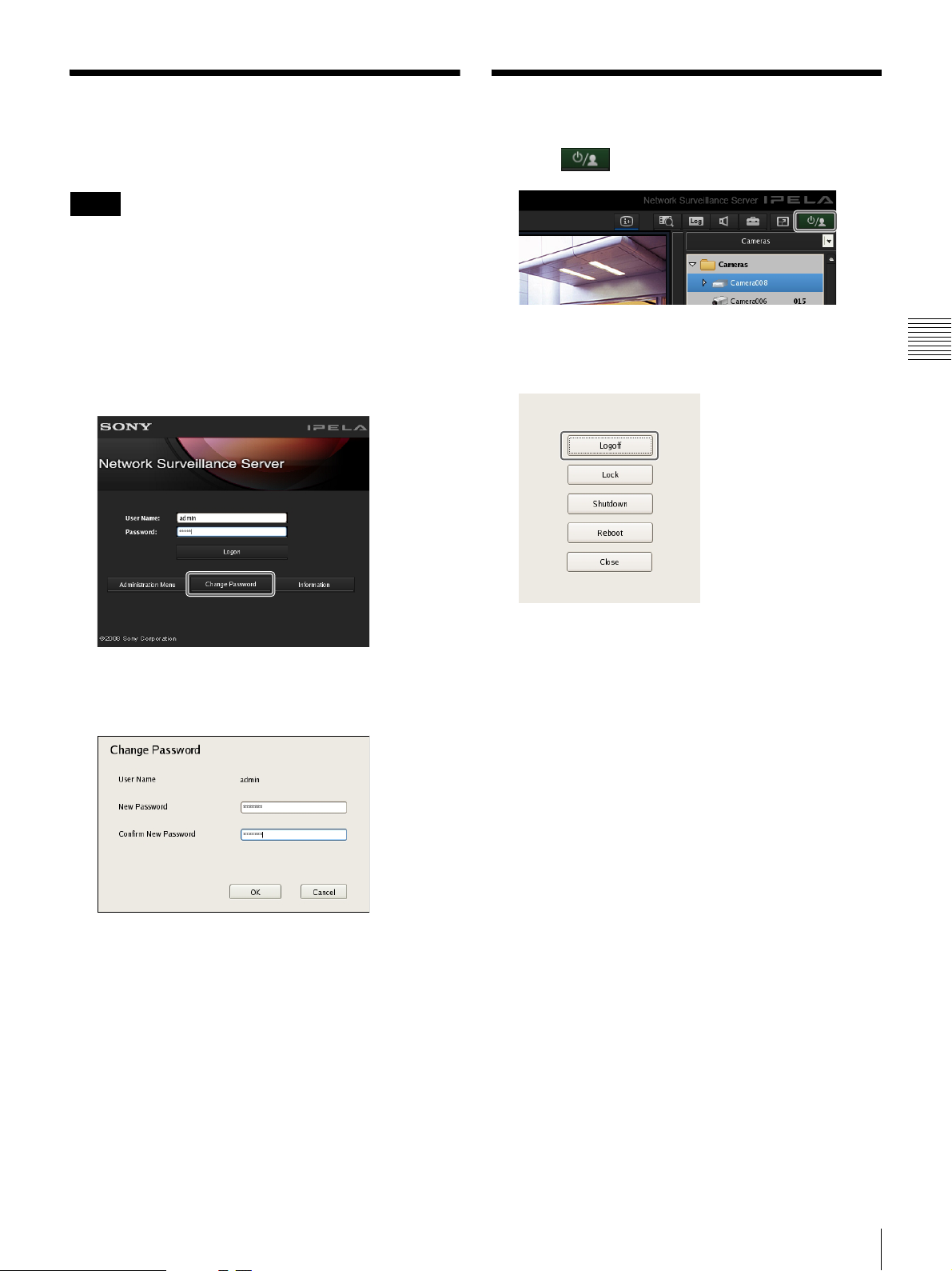
Changing the Password
Logging Off
You change the password for logging in to NSR.
Notes
• The password is extremely important to the security of
this equipment. The first time you log in to NSR after
purchasing the equipment, be sure to change the
password before monitoring and configuring various
settings. Take care to keep the password secure.
• When using a remote control for operations, create
passwords consisting only of numbers.
1
Click [Change Password] on the [Logon] screen.
1
Click in the Main screen.
The following screen appears.
2
Click [Logoff].
Chapter 3 Basic Operation
The Change Password dialog box appears.
2
Enter a new password, and click [OK].
Enter the same password again in [Confirm New
Password].
The password is changed.
A logoff confirmation message appears.
3
Click [OK].
You are logged off the NSR, and the logon screen
appears.
To log on again, enter the user name and password and
click [Logon].
Changing the Password / Logging Off
29
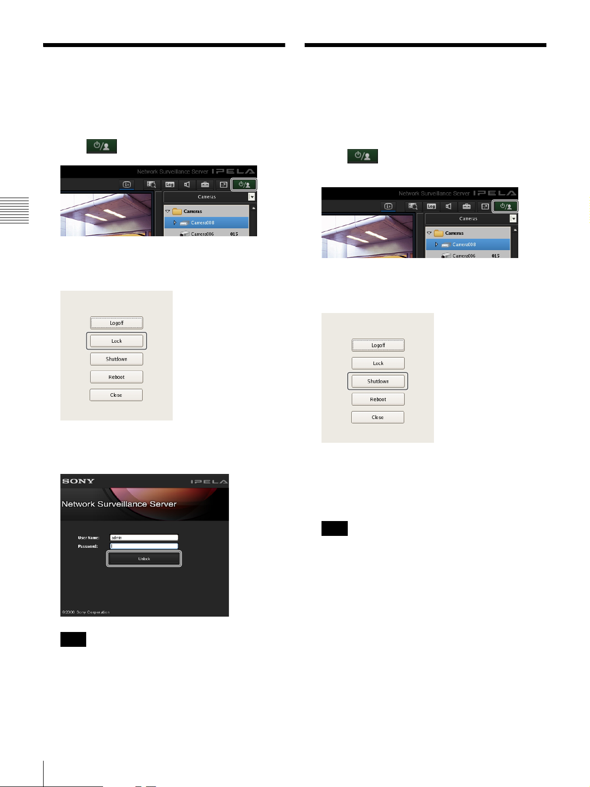
Locking the NSR
You can temporarily lock the screen in its current state.
Use the lock function when you need to leave your seat
during operation, for example.
1
Click in the Main screen.
Chapter 3 Basic Operation
The following screen appears.
Shutting Down and Restarting the NSR
Always shut down or restart the NSR from the Main
screen.
1
Click at the top of the Main screen, and select
[Shutdown] or [Reboot] from the menu that appears.
2
Click [Lock].
Operations are locked, and the logon screen appears.
To unlock operations, enter the user name and
password and click [Unlock].
The following screen appears.
2
Click [Shutdown] or [Reboot].
A confirmation message appears.
3
Click [OK].
The NSR shuts down or restarts.
Note
Under normal conditions, the NSR shuts down or
restarts after a few minutes. If the NSR does not shut
down or restart after several minutes, shut it down
manually by pressing the power switch located on the
rear of the unit in the 1 position for more then five
seconds.
Note
Only the user that is currently logged on or a level 5
user can undo the lock function.
30
Locking the NSR / Shutting Down and Restarting the NSR
Loading...