

Sony NSR-500 Series Installation Manual

Network
Surveillance
Server
4-272-492-05 (1)
Installation Manual ________ GB
設置説明書 ________________ JP
NSR-500 Series
Software Version 1.5.1 and Later
お買い上げいただきありがとうございます。
電気製品は安全のための注意事項を守らないと、
火災や人身事故になることがあります。
この取扱説明書には、事故を防ぐための重要な注意事項と製品の
取り扱いかたを示してあります。この取扱説明書をよくお読みのうえ、
製品を安全にお使いください。お読みになったあとは、
いつでも見られるところに必ず保管してください。
© 2010 Sony Corporation
Manuel d’installation ______ FR
Installationsanleitung ______ DE
Manuale all’installazione ___ IT
Manual de instalacion _____ ES

Before operating the unit, please read this
manual thoroughly and retain it for future
reference.
WARNING
To reduce the risk of fire or
electric shock, do not expose
this apparatus to rain or
moisture.
To avoid electrical shock, do not
open the cabinet. Refer
servicing to qualified personnel
only.
THIS APPARATUS MUST BE
EARTHED.
IMPORTANT NOTICE
This equipment is assigned a Model No.
PTOM001 for regulatory compliance
certifications. The number is indicated on
the model number label on your product
along with the rated voltage and current.
WARNING
When installing the unit, incorporate a
readily accessible disconnect device in the
fixed wiring, or connect the power plug to
an easily accessible socket-outlet near the
unit. If a fault should occur during
operation of the unit, operate the disconnect
device to switch the power supply off, or
disconnect the power plug.
WARNING
Using this unit at a voltage other than 120 V
may require the use of a different line cord
or attachment plug, or both. To reduce the
risk of fire or electric shock, refer servicing
to qualified service personnel.
Attention-when the product is
installed in Rack:
1. Prevention against overloading of branch
circuit
When this product is installed in a rack
and is supplied power from an outlet on
the rack, please make sure that the rack
does not overload the supply circuit.
2. Providing protective earth
When this product is installed in a rack
and is supplied power from an outlet on
the rack, please confirm that the outlet is
provided with a suitable protective earth
connection.
3. Internal air ambient temperature of the
rack
When this product is installed in a rack,
please make sure that the internal air
ambient temperature of the rack is within
the specified limit of this product.
4. Prevention against achieving hazardous
condition due to uneven mechanical
loading
When this product is installed in a rack,
please make sure that the rack does not
achieve hazardous condition due to
uneven mechanical loading.
5. Install the equipment while taking the
operating temperature of the equipment
into consideration
For the operating temperature of the
equipment, refer to the specifications of
the Operation Manual.
6. When performing the installation, keep
the following space away from walls in
order to obtain proper exhaust and
radiation of heat.
Right, Left : 4 cm (1.6 inches) or more
Rear : 10 cm (4 inched) or more
When installing the installation space must
be secured in consideration of the
ventilation and service operation.
• Do not block the ventilation slots at the
left side and right side panels, and vents
of the fans.
• Leave a space around the unit for
ventilation.
• Leave more than 40 cm of space in the
rear of the unit to secure the operation
area.
When the unit is installed on the desk or the
like, leave at least 4 cm of space in the left
and right sides. Leaving 40 cm or more of
space above the unit is recommended for
service operation.
2

WARNING: THIS WARNING IS
APPLICABLE FOR USA ONLY.
If used in USA, use the UL LISTED power
cord specified below.
DO NOT USE ANY OTHER POWER
CORD.
Plug Cap Parallel blade with ground pin
(NEMA 5-15P Configuration)
Cord Type SJT, three 16 or 18 AWG
wires
Length Minimum 1.5m (4 ft. 11in.),
Less than 4.5 m (15 ft.)
Rating Minimum 10A, 125V
Using this unit at a voltage other than 120V
may require the use of a different line cord
or attachment plug, or both. To reduce the
risk of fire or electric shock, refer servicing
to qualified service personnel.
WARNING: THIS WARNING IS
APPLICABLE FOR OTHER
COUNTRIES.
1. Use the approved Power Cord (3-core
mains lead) / Appliance Connector / Plug
with earthing-contacts that conforms to
the safety regulations of each country if
applicable.
2. Use the Power Cord (3-core mains lead) /
Appliance Connector / Plug conforming
to the proper ratings (Voltage, Ampere).
If you have questions on the use of the
above Power Cord / Appliance Connector /
Plug, please consult a qualified service
personnel.
IMPORTANT
The nameplate is located on the bottom.
For the customers in the U.S.A.
This equipment has been tested and found
to comply with the limits for a Class A
digital device, pursuant to Part 15 of the
FCC Rules. These limits are designed to
provide reasonable protection against
harmful interference when the equipment is
operated in a commercial environment.
This equipment generates, uses, and can
radiate radio frequency energy and, if not
installed and used in accordance with the
instruction manual, may cause harmful
interference to radio communications.
Operation of this equipment in a residential
area is likely to cause harmful interference
in which case the user will be required to
correct the interference at his own expense.
You are cautioned that any changes or
modifications not expressly approved in
this manual could void your authority to
operate this equipment.
All interface cables used to connect
peripherals must be shielded in order to
comply with the limits for a digital device
pursuant to Subpart B of Part 15 of FCC
Rules.
This device complies with Part 15 of the
FCC Rules. Operation is subject to the
following two conditions: (1) this device
may not cause harmful interference, and (2)
this device must accept any interference
received, including interference that may
cause undesired operation.
For the State of California, USA
only
Perchlorate Material - special handling may
apply, Seewww.dtsc.ca.gov/
hazardouswaste/perchloratePerchlorate
Material : Lithium battery contains
perchlorate.
For the customers in Canada
This Class A digital apparatus complies
with Canadian ICES-003.
For the customers in Europe,
Australia and New Zealand
WARNING
This is a Class A product. In a domestic
environment, this product may cause radio
interference in which case the user may be
required to take adequate measures.
GB
3
For the customers in Europe
The manufacturer of this product is Sony
Corporation, 1-7-1 Konan, Minato-ku,
Tokyo, 108-0075 Japan.
The Authorized Representative for EMC
and product safety is Sony Deutschland
GmbH, Hedelfinger Strasse 61, 70327
Stuttgart, Germany. For any service or
guarantee matters please refer to the
addresses given in separate service or
guarantee documents.
This apparatus shall not be used in the
residential area.
For kundene i Norge
Dette utstyret kan kobles til et ITstrømfordelingssystem.
For the customers in Taiwan only
4

Table of Contents
Usage Precautions .......................... 7
Package Contents ........................... 9
Downloading the Operating
Instructions and Tools ................. 10
System Requirements ................... 11
Using the CD-ROM manual ........ 12
Features and Functions................ 13
Reference Data for Installation ... 17
Preparation Steps ......................... 18
Step 1: Installation ....................... 19
Step 2: Connections ...................... 20
Step 3: Settings ............................. 24
Step 4: Verifying Operation ........ 39
Installing Patch Files .................... 40
Others ............................................ 41
I/O Port ................................... 41
Troubleshooting ...................... 42
Specifications ................................ 44
Trademarks
• “IPELA” and are
trademarks of Sony Corporation.
• HDMI, HDMI logo and High-Definition
Multimedia Interface are trademarks or
registered trademarks of HDMI
Licensing LLC.
• Other products or system names
appearing in this document are
trademarks or registered trademarks of
their respective owners. Further, the ™ or
® symbols are not used in the text.
Before using the unit, be sure to read
“END-USER LICENSE AGREEMENT”
in the User’s Guide (PDF).
• Reproduction or duplication, in whole
or part, of the software or operation
manual supplied with the server, as well
as renting or leasing of the software
without the authorization of the right
holder is prohibited under copyright
law.
• Sony assumes no responsibility for
damages, loss of income, or any claims
from a third party arising out of use of
the server or supplied software.
• For complete terms and conditions of
the warranty for the server, refer to the
warranty card included in the package.
• The software supplied with the server
cannot be used with any other servers.
• It is not possible to install any software
into the equipment other than the
software supplied by Sony specifically
for use with the equipment.
• Note that the specifications of the
server and supplied software are subjec t
to change for improvement without
prior notice.
Table of Contents
5

Servicing must only be
performed by trained
technicians
Handling of the interior of the unit by
general users may result in electrical shock
or injury.
Disclaimer of liability for
recorded content
Sony Corporation does not accept any
liability whatsoever for any problems
arising from a failure to record, or from
damage or erasure of recorded content on
this equipment, for any reason. This
includes claims for compensation of
recorded content, and for any concomitant
and consequential damages. Sony
Corporation will not repair, restore, or
duplicate any recorded content. Your use of
this product is subject to these conditions.
Table of Contents
6

Usage
Precautions
Important Information About
Safety
• Be sure to connect the unit to a power
source that conforms fully to the
electrical specifications of this unit.
• Do not coil the power cord or bundle it
with other cords. Do not piggy back
connections. If current ratings are
exceeded, there is a risk of fire and other
accidents.
• Make sure that all AC outlets and power
cords are properly grounded.
• Do not use the unit with the cover or case
opened or removed. Otherwise there is a
risk of fire and electric shock. Do not
attempt to open or remove the cover or
case yourself. Always consult your
supplier if opening is necessary.
Important Information About
Installation
Locations for use/storage
To prolong the life of the product, avoid use
or storage in the following locations.
• Locations that can become extremely hot
or cold. (Be sure to use the unit that
conforms fully to the specifications of
this unit.)
• Locations exposed for an extended time
to direct sunlight, and locations near
heating appliances. (Note that the
temperature in a closed car in summer
can exceed +50 ºC/+122 ºF.)
• Locations with high levels of humidity or
dust
• Locations subject to strong vibrations
• Locations subject to strong magnetic
fields
• Locations in the vicinity of radio or TV
transmitters creating a strong magnetic
field
Do not stack units or place the unit
on other objects that generate heat
When one unit is stacked on top of another
unit, the heat generated by both units can
get extremely hot. Do not stack units on top
of each other or place the unit on other
objects that may generate heat.
Do not block the ventilation
openings
• The ventilation openings on the sides of
the unit serve to prevent internal heat
buildup. Always leave a clearance on
both sides as well as behind and above
the unit.
• Do not use the unit in a closed box or
other enclosure.
Use the unit in a horizontal
position
• The unit is designed to be operated in a
horizontal position.
• Do not install the unit on a slanted
surface, and protect the unit from shocks.
• When the unit is dropped or otherwise
subject to strong shocks, it can be
seriously damaged.
Maintenance
• Before cleaning the unit or performing
any other kind of maintenance, be sure to
disconnect the power cord from the AC
outlet.
• For cleaning, lightly wipe the cabinet and
panels with a dry cloth. To remove
stubborn stains, lightly moisten the cloth
with a mild, neutral detergent and wipe
with a dry cloth afterwards.
• Do not use cleaning alcohol, solvents,
benzine, insecticide, or any other volatile
substances, because these may damage
the finish and lead to discoloration.
Usage Precautions
7

Transport
Use the original packing material or similar
packing to protect the unit from shocks.
even to very light shocks. After this period,
the hard disk will be fully stopped and the
unit can be manipulated.
Precautions for products with
built-in HDD
This unit has a built-in hard disk drive
(HDD). The HDD is a precision device. If
subject to shock, vibration, static
electricity, high temperature or humidity,
data loss can occur. When installing and
using the unit, closely observe the
following precautions.
Protect from shocks and
vibrations
When subject to shocks or vibrations, the
HDD can be damaged and loss of data on
the HDD can occur.
• When transporting the unit, use the
specified packing material. When
transporting on a dolly or similar, use a
type which does not transmit excessive
vibrations. Excessive shocks and
vibrations can damage the HDD.
• Never move the unit while it is powered.
• Do not remove panels or outer parts of
the unit.
• When placing the unit on a floor or other
surface, make sure that the unit is
equipped with the specified rubber feet,
and put the unit down carefully. If there
are no feet, mount the rubber feet first.
• Do not place the unit near other devices
that may become a source of vibrations.
Wait for 30 seconds after turning
power off
For a brief interval after the power is turned
off, the platters inside the HDD will still
keep spinning and the heads will be in an
insecure position. During this interval, the
unit is more susceptible to shocks and
vibrations than during normal operation.
For a period of at least 30 seconds after
turning power off, avoid subjecting the unit
Temperature and humidity related
precautions
Use and store the unit only in locations
where the specified temperature and
humidity ranges are not exceeded. (Be sure
to use the unit that conforms fully to the
specifications of this unit.)
When HDD seems to be faulty
Even if the HDD is showing signs of
malfunction, be sure to observe all the
above precautions. This will prevent further
damage from occurring until the problem
can be diagnosed and corrected.
Replacement of the HDD and other
consumable parts
The HDD, and battery of the unit are
consumable parts that will need periodic
replacement. When operating at room
temperature, the recommended
replacement cycle is about two to three
years. However, this replacement cycle
represents only a general guideline and does
not imply that the life expectancy of these
parts is guaranteed. For details on parts
replacement, contact your dealer.
Precautions for using USB devices
• This unit supports USB 2.0, Mass
Storage class devices. However, it does
not support USB 2.0, Mass Storage class
HDDs or CD/DVD drives. Do not
connect mass storage class devices other
than USB flash memory devices to the
unit. Be aware that errors may still occur
when writing data to a USB 2.0, Mass
Storage class memory device, depending
on the type of device used. If errors occur
when writing data, use a USB memory
device of a different type.
• To ensure proper operation of USB
devices, do not connect the devices via a
USB hub. Connect the devices directly to
Usage Precautions
8

the USB connectors on the unit.
Operation is not guaranteed when
devices are connected via a USB hub,
USB switch, or extension cable.
Package Contents
Protect data from power
interruptions
If the power supply is interrupted while the
unit is in operation, data may be damaged.
Always use an uninterruptible power
supply (UPS) to protect data.
Check that the following items are included
in this package:
• NSR-500 series (1)
• HDD cover key (2)
• Installation Manual (this document) (1)
• CD-ROM (User’s Guide) (1)
• WEEE booklet (1)
• Warranty booklet (1)
• Rubber feet (4)
• DVD-ROM (Setup Program) (1) (models
without HDD only)
• HDD screws (24) (models without HDD
only)
Notes
• This package may contain additional
hardware and/or documentation for those
options.
• Save the boxes and packing materials for
future use.
• The system controller (RM-NS1000) is
optional (sold separately).
Package Contents
9

Downloading the
Operating
Instructions and
Tools
You can download operating instructions
and copyright information for NSR and
tools such as RealShot Manager Advanced
(Client) as follows.
1 Use an FTP client such as Internet
Explorer to specify the following URL
on your computer.
ftp://ftptool@<NSR IP address>
2 Enter the following user name and
password.
User name: ftptool
Password: ftptool
Note
To change the user name and
password, change the [Enable user to
Get Tools from Remote] configuration
in “FTP” of the Setup Menu. In
addition, if you change the user name,
you must also change the address that
follows “ftp://” in the specified URL to
the new “user name@<NSR IP
address>.”
4 Download the necessary files directly
or from the specified links.
3 Click the folders that contain the files
you desire.
A list of downloadable files or a file
that contains links to locations from
which you can download will appear
for each folder.
Downloading the Operating Instructions and Tools
10

System
Requirements
The hardware required in order to use this
unit are as follows.
• Monitor
• Sony network cameras2) or Sony analog
• USB keyboard
•USB mouse
• Network hub
• 1000Base-T/100Base-TX/10Base-T
• USB flash memory device
1) Computer displays that accept RGB input are
2) Contact your dealer for details about
3) The NSR requires an NSBK-EB05 (optional)
4) Use a USB keyboard with a cable. However,
5) Use a USB mouse with a cable. Wireless or
1)
3)
cameras
cable
supported.
The supported resolutions are as follows.
- Full High-Definition (1,920 × 1,080)
- WUXGA (1,920 × 1,200)
- Full Wide XGA (1,360 × 768)
- UXGA (1,600 × 1,200)
- SXGA (1,280 × 1,024)
- XGA (1,024 × 768)
When NSBK-DH05 (optional) is
mounted
HDMI-compatible devices and computer
displays that accept RGB input are supported.
The supported resolutions are as follows.
- Full High-Definition (1,920 × 1,080)
- WUXGA (1,920 × 1,200)
- Full Wide XGA (1,360 × 768)
- UXGA (1,600 × 1,200)
- SXGA (1,280 × 1,024)
- XGA (1,024 × 768)
However, WUXGA is not supported on
HDMI-compatible devices.
compatible Sony network cameras.
expansion.
keys other than the standard may not function.
Wireless or infrared USB keyboards may also
not function properly.
infrared USB mice may not function properly.
Functions such as three-button and wheel
operations may also function improperly.
4)
5)
6)
6) Required when backing up system
information such as logs.
- This unit supports USB 2.0, Mass Storage
class devices. However, it does not support
USB 2.0, Mass Storage class HDDs or CD/
DVD drives. Do not connect mass storage
class devices other than USB memory
devices to the unit. Be aware that errors may
still occur when writing data to a USB 2.0,
Mass Storage class memory device,
depending on the type of device used. If
errors occur when writing data, use a USB
flash memory device of a different type.
System Requirements
11

Using the
CD-ROM manual
The supplied CD-ROM includes manuals
(User’s Guide) for this unit (Japanese,
English, French, German, Italian, Spanish
and Simplified Chinese versions). The
copies of these manuals are created in pdf
(Portable Document Format).
Preparations
One of the following programs must be
installed on your computer in order to use
the manuals contained on the CD-ROM
disc.
• Adobe Reader Version 6.0 or higher
Note
If Adobe Reader is not installed, you can
download it from the following URL:
http://www.adobe.com/
Note
Depending on the version of Adobe Reader
you are using, the file may not display
properly. If the file does not display
properly, download the latest version of
Adobe Reader from the URL found in the
“Preparations” section.
Caution
If you lose the CD-ROM disc or you cannot
read it for some reason, you can purchase a
new CD-ROM disc. Contact your nearest
Sony service representative.
Adobe and Adobe Reader are trademarks of
Adobe Systems Incorporated in the United
States and/or other countries.
Reading the CD-ROM
Manual
To read the manual on the CD-ROM,
proceed as follows.
1 Insert the CD-ROM into the CD-ROM
drive.
The manuals are saved in the “Manual”
folder.
2 Select and click the manual that you
want to read.
Using the CD-ROM manual
12
Features and Functions
12 3 4 5
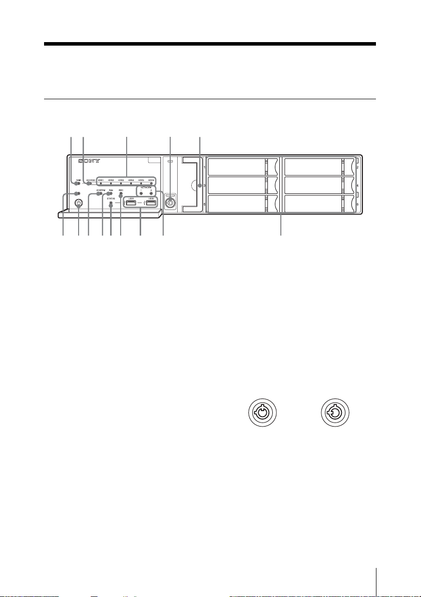
Front (When the Front Cover and the HDD Cover are Opened)
qdqs 90qaqf
A RAID LED
Lights green when the RAID
configuration is functioning properly.
Lights red if a fatal problem exists with
the RAID due to an internal HDD
failure, for example.
Lights amber if the RAID is degraded or
rebuilding.
B ACCESS LED
Blinks green when the HDDs are
accessed.
C HDD LEDs (1 to 6)
Light green when the internal hard disk
drives are functioning properly.
Light red when failures or other
problem occurs.
Also, light amber during the rebuilding
of RAID.
D Lock
Use this in conjunction with the
supplied HDD cover key to lock the
HDD cover.
768
When the HDD cover is locked, you
cannot remove it.
The fan unit is also locked when the
HDD cover is locked.
When attaching the HDD cover, make
sure the lock is the unlocked state before
you attach the cover.
You can distinguish the locked position
from the unlocked position by looking
at the lock, as illustrated below.
The HDD cover
is locked
E Fan unit
For details on maintenance, contact
your Sony dealer.
F HDDs
For details on maintenance, contact
your Sony dealer.
The HDD cover
is unlocked
Features and Functions
13
G NETWORK LEDs (1 and 2)
Light green when there is a link to the
network.
Blink amber when the network is being
accessed.
H USB connectors (1 and 2)
Use this connector to connect a USB
mouse, keyboard, USB flash memory,
or system controller (RM-NS1000) to
the unit.
M Power switch
Press this to turn on the unit.
If you press the power switch during
operation, the POWER LED blinks
green for up to 3 seconds.
Pressing the power switch again during
this time turns off the unit.
If 3 seconds elapse without the power
switch being pressed while the POWER
LED is blinking, the unit does not turn
off and operation continues.
I REC LED
Lights red when recording images.
J STATUS LED
Indicates the recognition status of USB
flash memory devices.
If a device is recognized, this lights
green.
If a device is not recognized, this lights
red.
Caution
Do not remove the USB flash memory
device while the LED is blinking.
K FAN LED
Lights green when the internal fan is
functioning properly. Lights red when a
fan failure occurs.
L SYSTEM LED
Blinks green while the unit is starting up
and then changes to always on when the
unit has started.
During operation, this LED is lit green
when the system is functioning
normally. When a system error or other
problem occurs, it lights red.
If this LED is lit red, contact your Sony
dealer.
Caution
Pressing and holding down the power
switch (approximately 5 seconds) turns
off the unit forcefully.
N POWER LED
Lights green when the unit is turned on.
If you press the power switch during
operation, the POWER LED blinks
green for up to 3 seconds.
Features and Functions
14
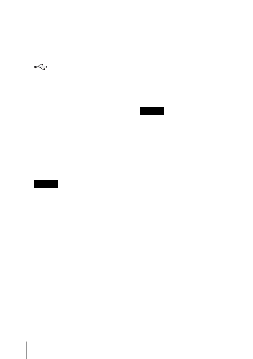
Rear
12345
q
7
q
NSR-500
qs 90qa
768
When NSBK-DH05 (optional) When NSBK-EB05 (optional)
is mounted is mounted
d
A Fan
Caution
Take care not to obstruct the fan grille.
If the grille is obstructed, heat may build
up in the unit, leading to damage and/or
fire.
B AUDIO OUT (line output) connector
(stereo)
Use these connectors to output audio to
a peripheral audio device.
C AUDIO IN (microphone input)
connector (used for future expansion)
Use this connector to input audio from a
peripheral audio device, such as a
microphone.
7
Plug-In Power microphones are
supported.
D RS-232C 1 (UPS) connector
Use this connector to connect the
control line of the uninterruptible power
supply (UPS).
E RS-232C 2 connector
Use this connector to connect analog
cameras via the analog camera input
cable.
This connector cannot be used at the
same time as the I RS-422/485
connector.
For pin assignment details and wiring
diagrams for sensor inputs, see “I/O
Port” (page 41).
f
Features and Functions
15
F LAN connectors (1 and 2)
Use these connectors to connect
10Base-T, 100Base- TX, or 1000BaseT network cables.
LAN1: Network cameras
1)
LAN2: Network cameras1) (LAN2 can
only be used when using a different
segment from LAN1.)
1) Connect remote clients to the network
specified with the [Network Interface for
Remote Client] setting (either LAN1 or
LAN2) in the Server Configuration
screen. For details, refer to the User’s
Guide (PDF).
Caution
• Do not configure LAN connectors 1
and 2 to the same network segment.
• For details on using iSCSI storage,
contact your Sony dealer.
CAUTION
• For safety, do not connect the
connector for peripheral device
wiring that might have excessive
voltage to the following ports.
- LAN1 connector
- LAN2 connector
Follow the instructions for the above
ports.
• When you connect the LAN cable of
the unit to peripheral device, use a
shielded-type cable to prevent
malfunction due to radiation noise.
connector cannot be used at the same
time.
H USB connectors (1 and 2)
Use this connector to connect a USB
mouse, keyboard, USB flash memory,
or system controller (RM-NS1000) to
the unit.
I RS-422/485 connector
Use this connector to connect analog
cameras via the analog camera input
cable.
This connector cannot be used at the
same time as the E RS-232C 2
connector.
For pin assignment details and wiring
diagrams for sensor inputs, see “I/O
Port” (page 41).
J ALARM OUT (alarm output)
connector
Use this connector to connect the alarm
output lines.
For connection details and a wiring
diagram for alarm output, see“I/O
Port” (page 41).
K SENSOR (sensor input) connector
Use this connector to connect the sensor
input lines.
For connection details and wiring
diagrams for sensor inputs, see “I/O
Port” (page 41).
G Monitor connectors (1 and 2)
Use this connector to connect a monitor
that supports analog RGB input.
Caution
If the optional NSBK-DH05 is installed,
monitor connector 1 will not be
available for use. Only monitor
connector 2 will be available. Monitor
connector 2 and the HDMI monitor
Features and Functions
16
L Power supply connector
Use this connector to connect the power
cord.
M HDMI monitor connector
Use this connector to connect a monitor
that supports HDMI input.
Monitor connector 2 and the HDMI
monitor connector cannot be used at the
same time.

This connector can only be used when
an NSBK-DH05 (optional) is mounted.
N Analog camera cable input connector
Use this connector to connect the analog
camera input cable.
This connector can only be used when
an NSBK-EB05 (optional) is mounted.
CAUTION
When you connect the analog camera
input cable of the unit to peripheral
device, use the supplied cable to prevent
malfunction due to radiation noise.
Reference Data
for Installation
Current Consumption and
Inrush Current
Model AC input
NSR500:12
voltage
100 V 0.57 A
230 V 0.34 A
Storage Capacity for
Recorded Data
Full
loading
Inrush
current
11 A
You can confirm the configurations and the
hard disk drive capacity of the NSR
clicking [Information] in the Logon screen,
and viewing the Information screen that
appears. You can also confirm the actual
storage capacity
recorded in the [Storage] tab of the Server
screen.
1) Capacities for hard disk drives are
approximations based on the following
equation for 1 GB: 1,000 × 1,000 × 1,000 =
1,000,000,000 bytes
2) Storage capacities are approximations based
on the following equation for 1 GB: 1,024 ×
1,024 × 1,024 = 1,073,740,000 bytes
2)
to which data can be
1)
by
Number of Cameras
At the time of purchase, the maximum
number of cameras that can be registered is
16.
Installing the optional NSBK-CL05
increases the maximum number of cameras
that can be registered to 24.
Reference Data for Installation
17
Note
For details on the expansion limit for the
number of cameras, contact your Sony
dealer.
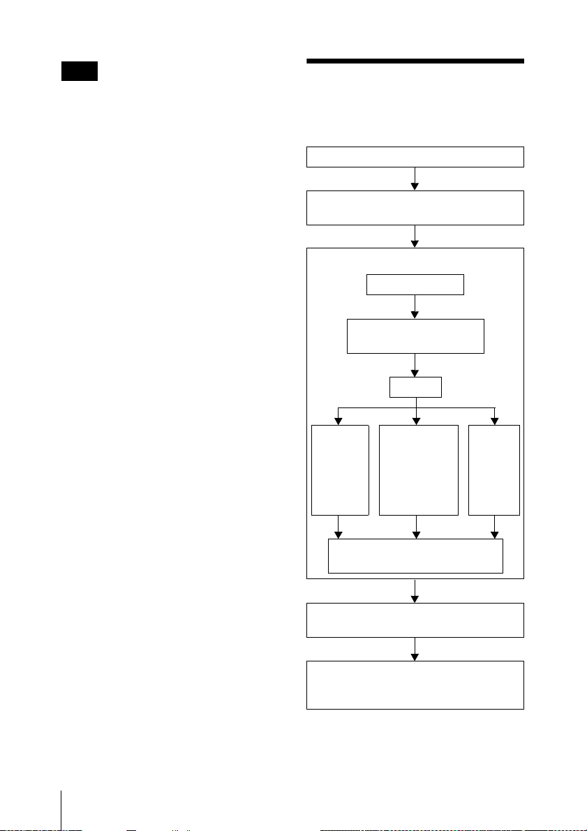
Preparation Steps
Maximum number of analog
cameras (included in maximum
camera count)
16 cameras (with optional NSBK-EB05
installed)
Step 1: Installation (page 19)
Step 2: Connections (page 20)
Connect each device to the unit.
Step 3: Settings (page 24)
Turn on the unit.
Configure initial settings
with the Setup Wizard.
Log on.
Perform
registration
with Easy
Setup.
Configure automatic record
settings.
Select
automatically
detected
cameras and
register them
simultaneously.
Register
devices
manually.
18
Step 4: Verifying Operation
(page 39)
If advanced configuration is
necessary
Refer the User’s Guide (PDF).
Preparation Steps
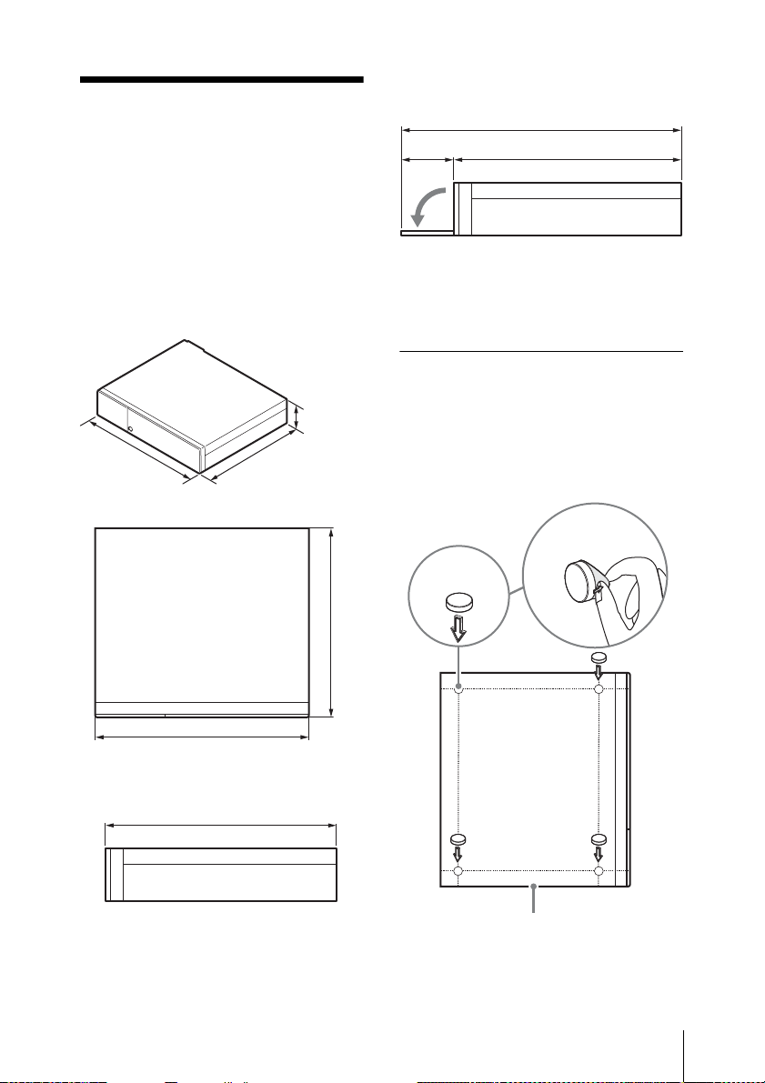
Step 1:
Installation
Before setting up, be sure that the location
for installation provides sufficient space
and strength to support the unit.
For the unit weight, see “Specifications”
(page 44).
The dimensions for the unit are as follows.
When the front cover is opened
470 mm (18 5/8 in.)
1
392 mm (15
/2 in.)78 mm (31/8 in.)
When installing the unit on a rack, use the
rack mount kit designed specifically for this
unit. For details on the rack mount kit,
contact your Sony dealer.
Installation Without a Rack
89 mm
(3
440 mm
3
(17
/8 in.)
392 mm
1
(15
/2 in.)
Top
TOP
440 mm (173/8 in.)
When the front cover is closed
392 mm (151/2 in.)
5
/8 in.)
1
Attach the provided rubber feet to the unit.
Place the unit upright so that the bottom
surface is visible. Then affix the adhesive
surfaces of the rubber feet on the bottom of
the unit as illustrated below.
Remove
the film
Rubber
foot
/2 in.)
392 mm (15
Bottom of the unit
Step 1: Installation
19
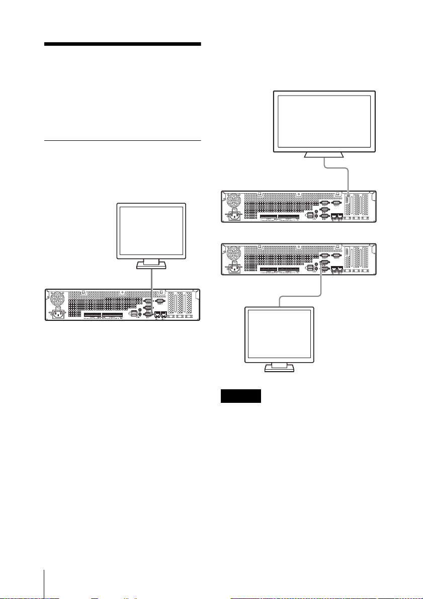
Step 2:
Connections
Connect each device to the unit.
Connecting the Monitors
Connect the monitor to monitor connector
1.
Monitor
With the optional NSBK-DH05
installed
Connect the monitor to monitor connector 2
or the HDMI monitor connector.
HDMI monitor connector
or
Monitor connector 1
Monitor connector 2
Caution
• When monitors are connected via a
monitor switch, images may not always
display. We recommend connecting
monitors directly to the unit.
• Monitor connector 2 and the HDMI
monitor connector cannot be used at the
same time.
Step 2: Connections
20
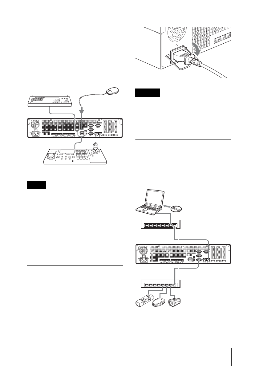
Connecting the Keyboard,
Mouse and System
Controller
Connect the devices to the USB connectors
on the unit.
Example)
Keyboard
Mouse
System controller
Notes
• This unit supports RM-NS1000 system
controller and IP Desktop USB
controllers from CH Products. Other
remote controllers are not supported. Do
not connect more than one remote
controller.
• When using USB devices, be sure to read
“Precautions for using USB devices”
(page 8) in the “Usage Precautions”
section beforehand.
Caution
Before installing, carefully read “Important
Information About Safety” (page 7). When
using the unit in combination with multiple
NSR units, make sure that the power supply
is sufficient.
Connecting to a Network
Connect to the network as follows.
Remote client
Connect LAN connector to the same
network as the Windows PC being used as
the remote client.
Windows PC
RealShot Manager
Advanced
Client software
Network hub
LAN connecter 2
Connecting the Power
Cord
Connect the power cord to the power supply
connector.
Attach the safety clip to prevent the power
cord from disconnecting.
Network hub
Network cameras
Connect LAN connector 1 to the same
network as the network cameras.
LAN connecter 1
Step 2: Connections
21
Connections to remote clients
When a remote client is necessary, you can
use the RealShot Manager Advanced client
software supplied with this unit.
• Use the version of RealShot Manager
Advanced supplied with this unit. For
details on how to download the installer
for RealShot Manager Advanced, see
“Downloading the Operating
Instructions and Tools” (page 10). For
details on installation and connecting to
the NSR, refer to the RealShot Manager
Advanced Installation Guide (PDF).
• RealShot Manager Advanced client
software operates on Windows
computers. For details on recommended
system specifications, refer to the release
notes included in the install archive for
RealShot Manager Advanced client
software.
• When using RealShot Manager
Advanced as a remote controller for the
NSR, select [Client] during installation
of RealShot Manager Advanced.
• When connecting to the user area
network, use LAN connector 2.
• For details on NSR settings when using
the RealShot Manager Advanced client
software, see “Configurations for Using
RealShot Manager Advanced Client
Software” (page 38).
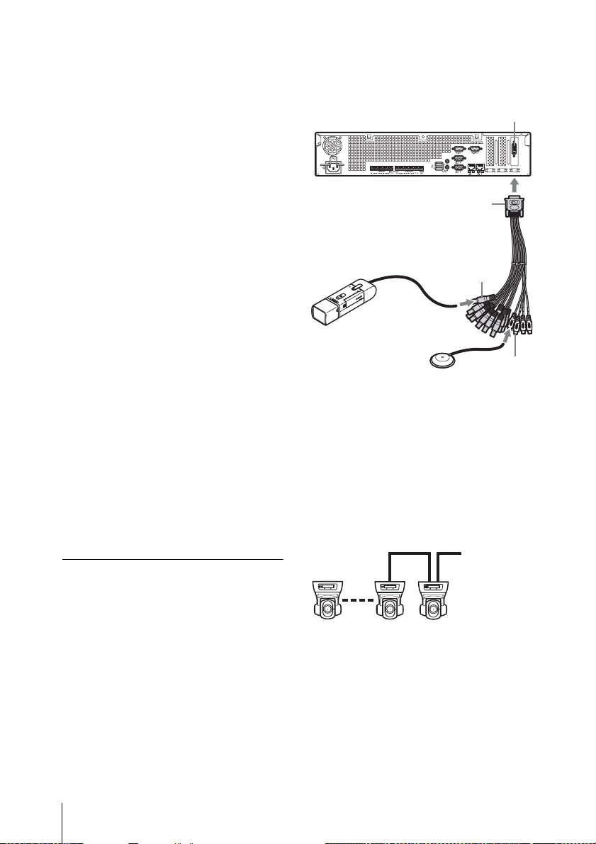
Connecting an Analog
Camera (when NSBK-EB05
(Optional) is Mounted)
Use the analog camera input cable supplied
with the NSBK-EB05 (optional) to connect
the analog cameras.
To control pan, tilt, and zoom operations,
connect a camera control cable to the
RS-232C 2 connector or the RS-422/485
connector (four rightmost pins on the alarm
output connector). (Only one of these
connectors (RS- 232C, RS-422, RS-485)
can be used at any one time.)
Analog camera cable
input connector
Analog camera input cable
Analog camera
Audio device
Video input
connector (black)
Audio input
connector
(white)
Connections for controlling
pan, tilt, and zoom
For RS-232C (VISCA)
communication
Configure a daisy chain connection as
follows.
Maximum number of cameras: 7
To RS-232C 2
connector
Analog
camera
PTZ
Step 2: Connections
22
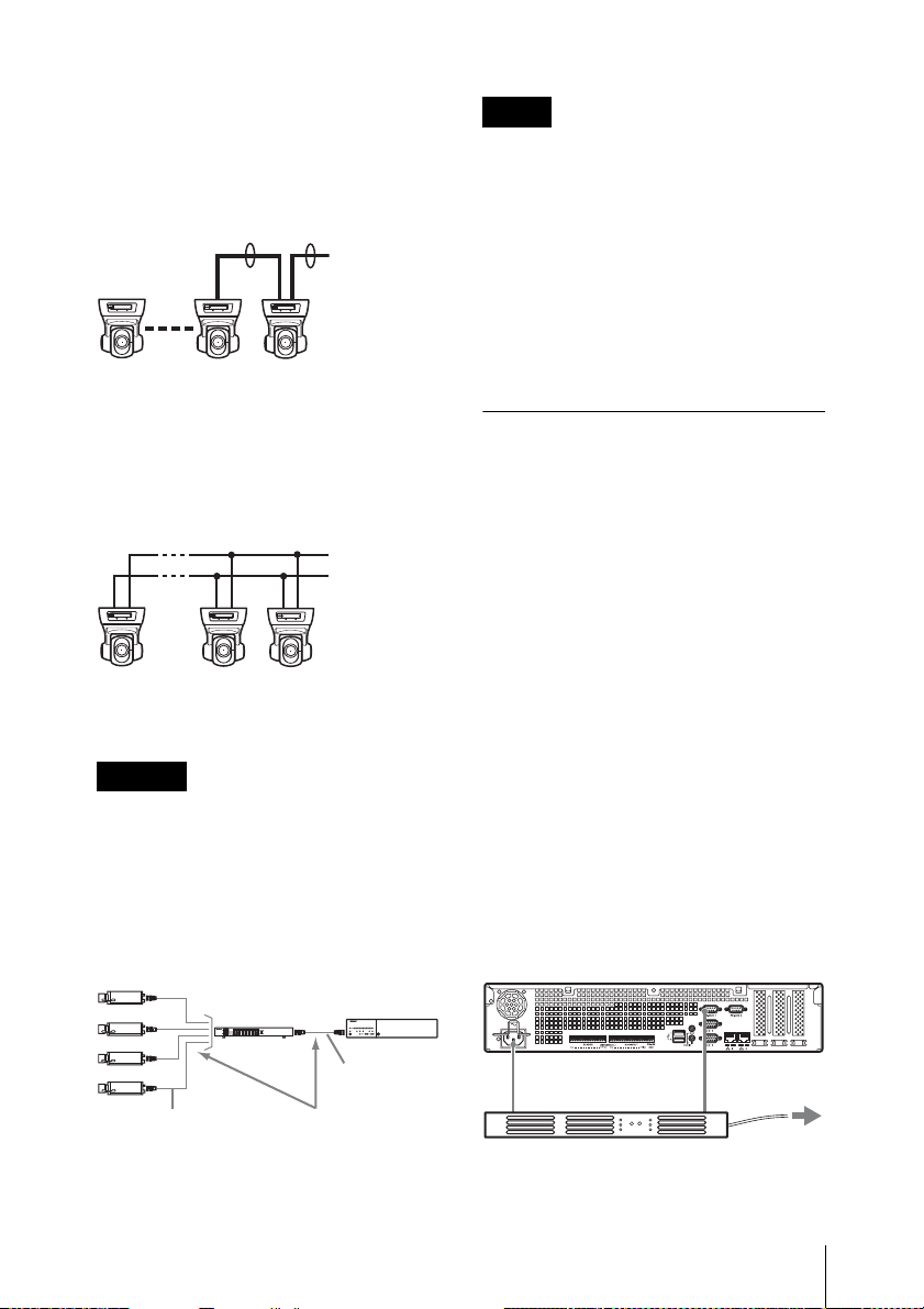
For RS-422 (VISCA, PELCO-D)
Anal
communication
Configure a daisy chain connection as
follows.
Maximum number of cameras: 7
4
4
To RS-422
connector
Analog
camera
PTZ
For RS-485 (PELCO-D)
communication
Configure a star connection as follows.
Maximum number of cameras: 16
To RS-485
connector
Notes
• To perform pan, tilt, and zoom, control
numbers must be configured. Be sure that
the numbers do not overlap when
multiple analog cameras are connected.
For details on configuring control
numbers, refer to the operating
instructions for the analog camera.
• For details on the pin assignment for the
RS-422/485 connector, see “Pin
Assignment of I/O Port” (page 41).
Connecting Other Devices
Connecting Sensor Inputs
and Alarm Outputs
Connect the wires to the sensor input
connector and the alarm output connector.
For details, see “I/O Port” (page 41).
Analog
camera
PTZ
Caution
When using cameras and power supply units
that superimpose DC voltage on the video
coaxial cable, pay close attention to the coaxial
cable wiring. If the camera cable on which DC
voltage is superimposed is connected to the
NSR, malfunctions may occur.
og
cameras
Coaxial cable
on which DC
voltage is
superimposed
Power
supply
unit
VIDEO
OUT
Coaxial cable
Be careful not to connect
the coaxial cable for the
analog cameras to the
NSR unit.
NSR
Connecting an
Uninterruptible Power Supply
(UPS)
1 Connect the UPS to the power outlet.
2 Connect the NSR to the UPS with the
power cord.
3 Connect the NSR to the UPS with the
dedicated serial cable to the
RS-232C 1 (UPS) connector on the
rear of the NSR.
Power cord
Serial cable
To Power sourceUPS
Step 2: Connections
23
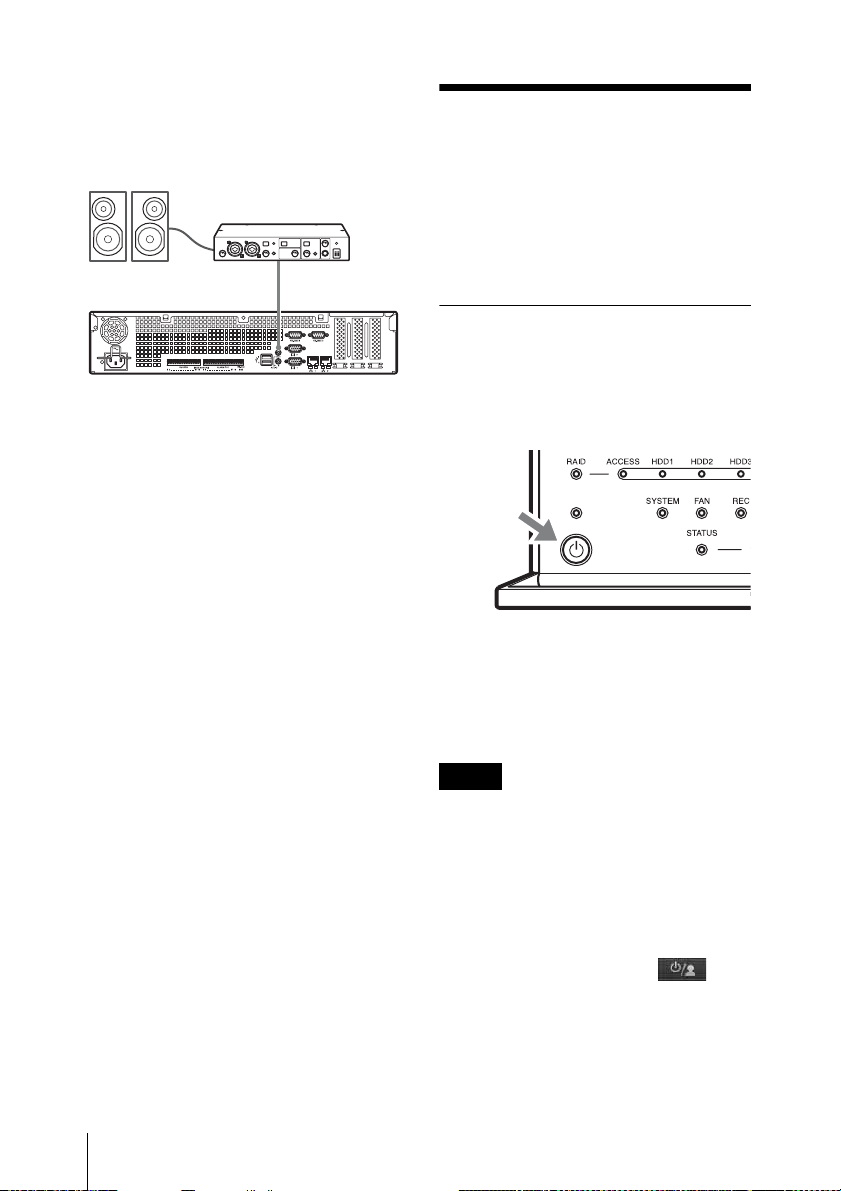
Connecting an Audio Output
Device
Connect the audio output device to the line
output connector.
Audio cable
Step 3: Settings
This section provides information on how
to turn on the unit, and general explanations
on how to register cameras and other
devices.
Turning On the Unit
When you press the power switch on the
front panel of the unit, the unit turns on and
the POWER LED on the front panel lights
green.
When you turn on the unit for the first time,
the Setup Wizard starts automatically.
Continue to the following section,
“Configuring Initial Settings with Setup
Wizard.”
24
Notes
• The fan noise may be loud after turning
on the unit. This is not a malfunction.
• If a forced shutdown was performed
previously, the unit may take longer to
start up.
To turn off the unit
After logging on to NSR, click at the
top of the “Main” screen, and select
[Shutdown] from the menu that appears.
Step 3: Settings
Also, if you press the power switch, and
then press the power switch again while the
POWER LED is blinking green (for up to 3
seconds), the unit begins the shutdown
process and then the power turns off after
several minutes.
Note
If the unit does not turn off after a while,
press and hold the power switch on the front
of the unit (for about 5 seconds) to force the
power to turn off.
Configuring Initial Settings
with Setup Wizard
This section explains the general flow of the
Setup Wizard. For further details on
settings, refer to “Changing Initial Settings
with the Setup Menu” in the User’s Guide
(PDF).
r
Click [Next].
The Setup Wizard starts automatically
when you turn on the unit for the first time.
You can configure the same settings
afterward by accessing the logon screen, the
Administration Menu, and then the Setup
Menu.
For details, refer to “To access the Setup
Menu from the logon screen” (page 28).
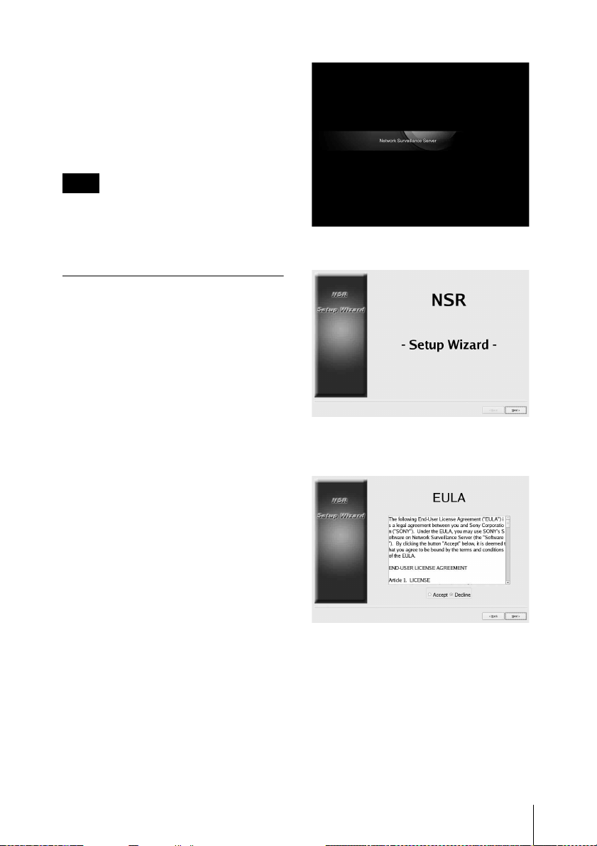
When you turn on the unit, the Setup
Wizard starts after the following screen
appears.
r
Read the user license agreement carefully,
click [Accept], and then click [Next].
r
Select a display language, and click [Next].
Step 3: Settings
25
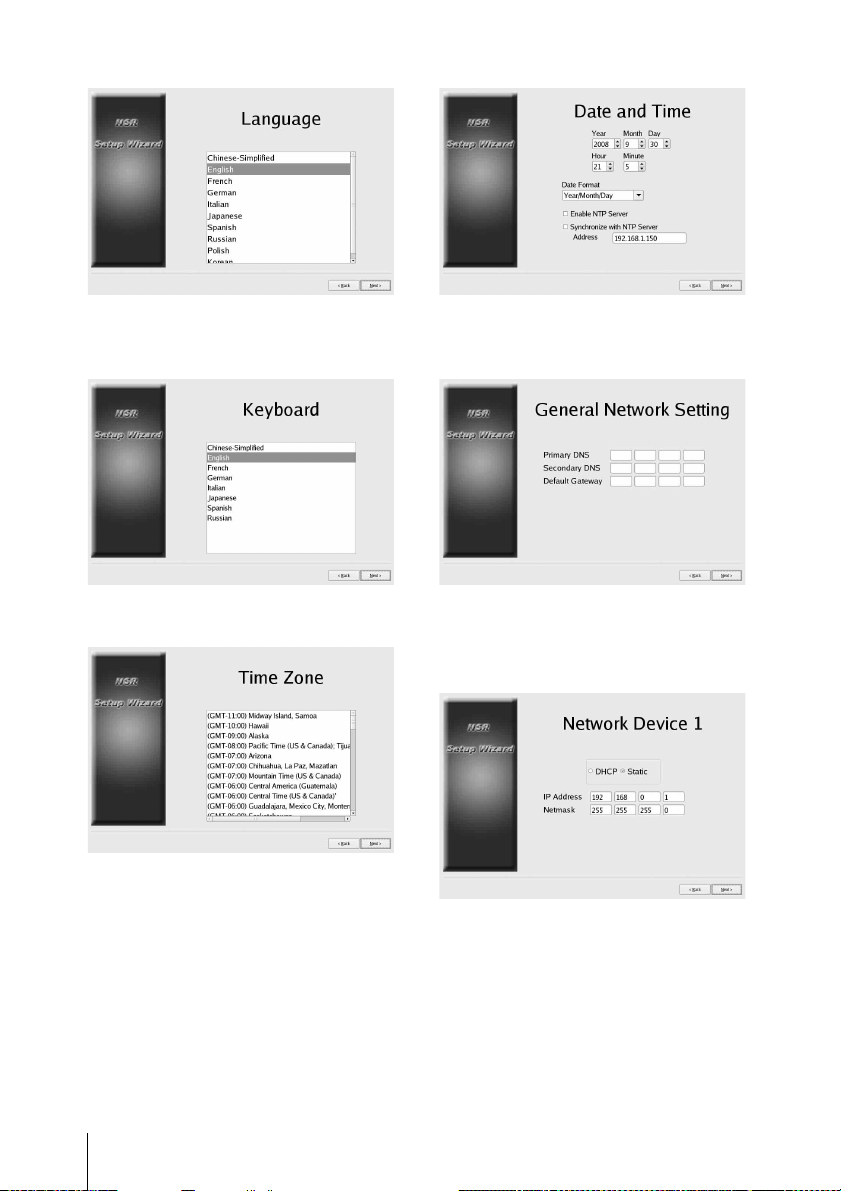
r
Select a language for the keyboard, and
click [Next].
r
Set the IP address for each server, and click
[Next].
r
Select a time zone, and click [Next].
Set the date and time, and click [Next].
• When you select the [Enable NTP
Server] check box, the unit acts as the
NTP server for date and time
synchronization.
• When you select the [Synchronize with
NTP Server] check box, you can
synchronize the date and time with a
different NTP server.
Step 3: Settings
26
r
Set the IP address for LAN connector 1, and
click [Next].
r
r
Set the IP address for LAN connector 2, and
click [Next].
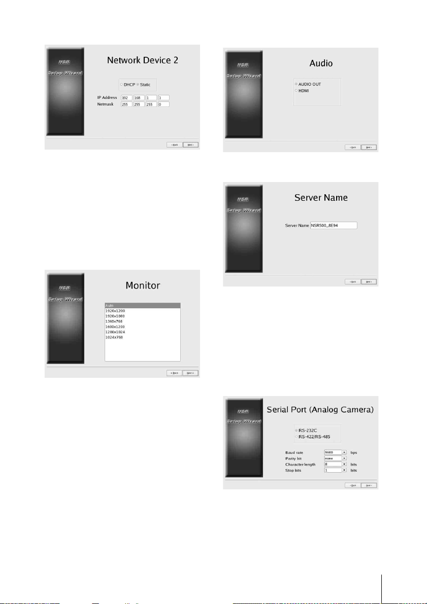
r
Select the resolution of the monitor
connected to the unit, and click [Next].
If you select [Auto], the maximum
resolution of the connected monitor will be
detected and selected automatically.
The maximum resolution will also be
detected and selected automatically if the
connected monitor does not support the
resolution you select.
r
Select the audio output connector to use,
and click [Next].
When using audio output from an HDMI
monitor, select [HDMI]. ([HDMI] can only
be selected when an optional NSBK-DH05
is installed.)
r
Set the server name, and click [Next].
r
Configure analog camera connection
settings, and click [Next].
Select the serial transmission standard with
which the camera you want to control will
be connected, and configure settings such
as baud rate and parity bits.
(This screen only appears when an optional
NSBK-EB05 is installed.)
r
Select the video format for the analog
cameras to be connected, and click [Next].
(This screen only appears when an optional
NSBK-EB05 is installed.)
Step 3: Settings
27
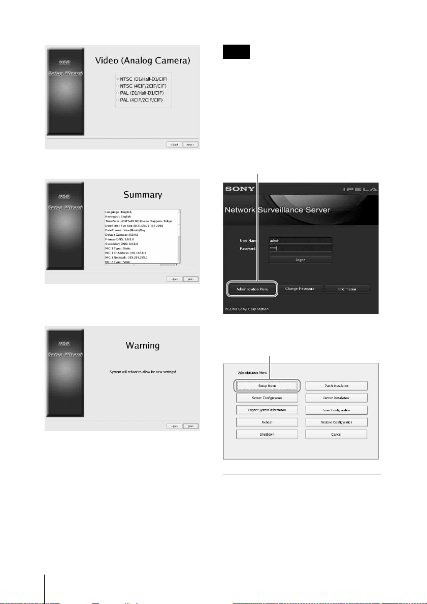
r
1
2
Verify configurations, and click [Next].
r
Click [Finish] when the restart confirmation
message appears.
Note
If you want to reconfigure the settings after
configuring them with the Setup Wizard,
you can reconfigure them from the login
screen.
To access the Setup Menu
from the logon screen
Click [Administration Menu].
r
Click [Setup Menu].
The unit restarts.
The logon screen appears.
Continue to the following section,
“Logging On.”
Step 3: Settings
28
r
r
Installing Licenses
You can install a license on the NSR to
enable registration of additional cameras.
You can register up to 16 cameras under
factory default conditions, but this can be
increased to up to 24 cameras.
Notes
• For details on licenses, refer to the
NSBK-CL05 Installation Guide (PDF).
• For details on acquiring licenses, contact
your Sony dealer.
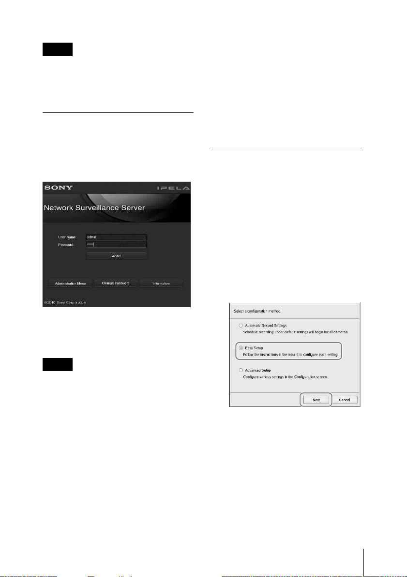
Logging On
Enter the user name and password, and
click [Logon].
Default user name: admin
Default password: admin
r
When logon is successful, the Camera Auto
Registration dialog appears.
not appear on subsequent startup of the
software, and cameras will not be
located. If you selected this check box
previously and want to perform
automatic camera registration again later,
configure settings in the [Administration
Menu] to reenable display of this dialog
box. For details on the [Administration
Menu], refer to the User’s Guide (PDF).
Registering Cameras
You can register cameras using one of the
following methods: register cameras using
Easy Setup; select cameras that were
automatically detected and then register
them simultaneously; or register devices
manually.
Registration using Easy Setup
Follow the instructions of the wizard to
configure each setting.
1 Select [Easy Setup], and click [Next].
Notes
• Only Sony cameras will be located and
registered.
• Only cameras with IP address settings
that have not been changed from factory
default conditions will be located and
registered. To register cameras with IP
addresses that have been changed, use
[Easy Setup] (page 29), or return the
camera IP address settings to default
conditions and restart the unit.
• If you want to manually specify cameras
for registration, click [No] and proceed to
the next section, “Registering Cameras.”
• If you select the [Do not show this dialog
box again] check box, this dialog box will
The Easy Setup wizard appears.
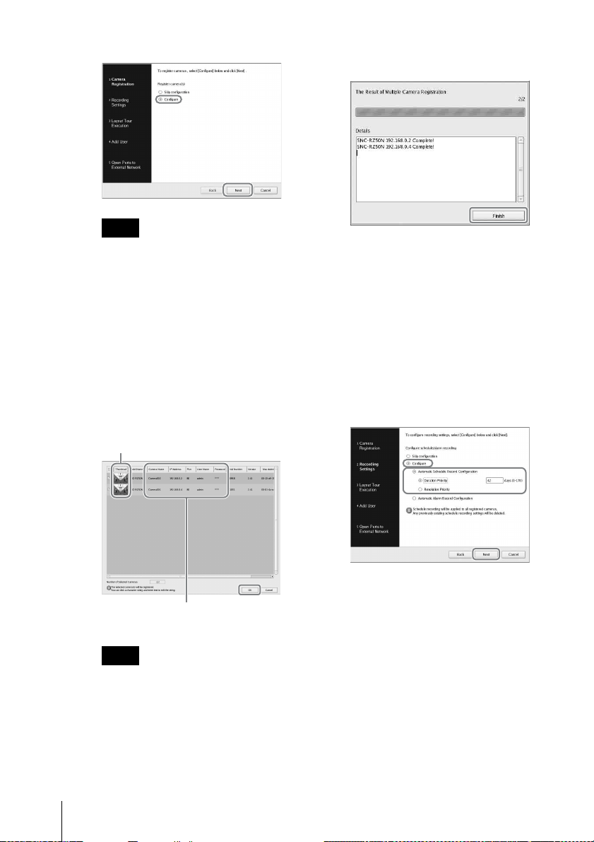
2 Register the cameras.
If you do not want to register cameras,
select [Skip configuration] and click
[Next], and proceed to step 3.
1 Select [Configure], and click
[Next].
Step 3: Settings
29
Note
To return to the previous screen and
reconfigure settings, click [Back].
3 Click [Finish].
Proceed to “3 Recording
Schedule”.
The Camera Registration screen
appears.
2 Select the check boxes for the
cameras you want to register, and
click [OK].
The cameras are registered in the
order that they appear in the list.
Images from the camera are
displayed.
Click on a text string to enable
text entry modification.
Note
If you clear the check box for a
camera that is already registered
and click the [OK] button, the
registration will be canceled.
3 Configure recording settings.
If you do not want to configure
recording settings, select [Skip
configuration] and click [Next], and
proceed to step 4.
1 Select [Configure], select the
recording method, and click [Next].
Automatic Schedule Record
Configuration
Perform schedule recording using
settings automatically configured
based on the number of cameras
and storage capacity.
When you select this setting, be
sure to also select [Duration
Priority] or [Resolution Priority].
30
When registration completes, the
following screen appears.
Step 3: Settings
 Loading...