

Page 1

Network
Surveillance
4-272-495-16 (1)
Server
User’s Guide
Software Version 1.6 and Later
Before operating the unit, please read this manual thoroughly
and retain it for future reference.
NSR-500 Series
© 2011 Sony Corporation
Page 2

Table of Contents
Chapter 1 Introduction
Overview...........................................................................................6
Features and Functions ..................................................................8
System Requirements ...................................................................11
Front (When the Front Cover and the HDD Cover are Opened) .......... 8
Rear ....................................................................................................... 9
Chapter 2
Administration Menu
Overview.........................................................................................12
Displaying the Administration Menu ...........................................12
Changing Initial Settings with the Setup Menu...........................13
Displaying Setup Menu ....................................................................... 13
Details on Setting Items ...................................................................... 13
Configuring Settings Related to Servers.....................................18
Installing Patch Files.....................................................................20
Saving and Restoring Configuration Data ..................................21
Saving Configuration Data.................................................................. 21
Restoring Configuration Data ............................................................. 22
Exporting System Information .....................................................23
Installing Licenses.........................................................................24
Chapter 3 Basic Operation
Overview.........................................................................................25
Logging On to the NSR .................................................................25
Basic Window Operations ............................................................27
Changing the Password................................................................30
Logging Off ....................................................................................31
Locking the NSR ............................................................................31
Shutting Down and Restarting the NSR ......................................32
Viewing Version Information ........................................................32
2
Table of Contents
Page 3

Chapter 4
Application Settings
Alarms and Events ........................................................................33
Displaying Configuration Window ...............................................33
Registering Devices ......................................................................34
Changing Registration Details............................................................. 34
Deleting Devices ................................................................................. 35
Settings Required when Using SNC-CS20/CM120/DS10/DM110/
DS60/DM160............................................................................. 35
Registering Device Groups ................................................................. 36
Details of Each Screen ........................................................................ 37
Configuring Camera Video Settings ............................................41
Configuring Camera Operations ..................................................45
Configuring Preset Positions ............................................................... 45
Configuring Camera Tours.................................................................. 46
Configuring Shadow Tours ................................................................. 47
Configuring Masks (Camera).............................................................. 48
Configuring Control Protocols for Analog Cameras........................... 50
Configuring Network Camera Control................................................ 50
Configuring Audio .............................................................................. 51
Settings Related to Monitoring.....................................................51
Configuring Monitor Layout Settings ................................................. 51
Assigning Cameras to Monitor Frames............................................... 57
Configuring Layout Tours................................................................... 57
Configuring Motion Detection Settings .......................................59
Using the Motion Detection Function of the Camera
(VMD (Camera)) ....................................................................... 59
Configuring Camera Tamper Detection and Audio Detection... 61
Configuring Edge Storage Settings.............................................62
Configuring Settings Related to Storage ....................................63
Configuring Storage Settings .............................................................. 63
Configuring Settings Related to Deleting Recording Data ................. 66
Configuring Recording Schedules...............................................69
Configuring Schedules Manually........................................................ 69
Configuring Alarm Recording and Event Recording.......................... 71
Configuring Sensor Inputs ...........................................................76
Changing Settings of Sensor Input Pins of NSR................................. 76
Changing Settings of Sensor Input Pins of Camera ............................ 76
Changing Settings of Sensor Input Pins of Barionet........................... 77
Adding Logical Sensor Input Pins to NSR.......................................... 77
Deleting Logical Sensor Input Pins Created for NSR......................... 78
Setting Items of the [Logical Sensor In] Tab ...................................... 78
Configuring Alarm Output Settings .............................................79
Changing Settings of Alarm Output Pins of NSR............................... 79
Table of Contents
3
Page 4

Changing Settings of Alarm Output Pins of Camera .......................... 79
Changing Settings of Alarm Output Pins of Barionet......................... 80
Setting Items of the [Alarm Out] Tab ................................................. 80
Configuring Action Settings .........................................................82
Manual Action..................................................................................... 82
Event/Alarm Actions........................................................................... 85
Configuring Mail Notification Settings ........................................89
Configuring System Alert Settings ..............................................90
Registering Users ..........................................................................91
User Levels and Permissions............................................................... 91
Registering a User ............................................................................... 92
Changing User Settings ....................................................................... 93
Deleting a User.................................................................................... 93
Setting Items of the [User] Tab ........................................................... 93
Configuring the Duration to Rewind for Quick Playback...........95
Chapter 5
Operation and Control
Monitoring ......................................................................................96
Monitoring Live Images...................................................................... 96
Monitoring Using Layout Tours.......................................................... 97
Monitoring Audio from Cameras ........................................................ 97
Functions and Operating Procedure of Main Screen........................... 98
When a Click Action is Configured .................................................. 103
Monitor Frame................................................................................... 103
Controlling Cameras ...................................................................104
Performing Pan, Tilt, and Zoom Operations ..................................... 104
Using Camera Presets........................................................................ 105
Performing Camera Tours ................................................................. 106
Recording, Searching, and Playing Images ..............................106
Recording Live Images ..................................................................... 106
Playing Recorded Images.................................................................. 107
Searching Recorded Images .............................................................. 108
Playing Recorded Images from Search Results ................................ 108
Details of Search Window................................................................. 108
Deleting Recorded Images..........................................................110
Protecting Recorded Images ......................................................111
Exporting Recorded Images .......................................................112
Exporting Recorded Images .............................................................. 112
Exporting Recorded Images as Still Images...................................... 114
System Administration................................................................115
Monitoring the Error Status............................................................... 115
4
Table of Contents
Page 5

Chapter 6 Appendix
Exporting Log Files........................................................................... 116
END-USER LICENSE AGREEMENT ...........................................118
Concerning GPL-LPGL................................................................119
MPEG-4 Video Patent Portfolio License....................................120
GNU GENERAL PUBLIC LICENSE .............................................120
Preamble............................................................................................ 120
TERMS AND CONDITIONS FOR COPYING, DISTRIBUTION
AND MODIFICATION........................................................... 121
END OF TERMS AND CONDITIONS ...........................................124
How to Apply These Terms to Your New Programs ........................ 124
GNU LESSER GENERAL PUBLIC LICENSE..............................125
Preamble............................................................................................ 125
TERMS AND CONDITIONS FOR COPYING, DISTRIBUTION
AND MODIFICATION........................................................... 126
END OF TERMS AND CONDITIONS ...........................................130
How to Apply These Terms to Your New Libraries ......................... 130
Index ............................................................................................132
Trademarks
• “IPELA” and are trademarks of Sony Corporation.
• The terms HDMI and HDMI High-Definition Multimedia Interface, and the HDMI Logo are trademarks or registered
trademarks of HDMI Licensing LLC in the United States and other countries.
• Other products or system names appearing in this document are trademarks or registered trademarks of their respective owners.
Further, the ® or ™ symbols are not used in the text.
Before using the unit, be sure to read "END-USER LICENSE AGREEMENT" in this manual.
Table of Contents
5
Page 6
Chapter 1 Introduction
Introduction
Chapter
1
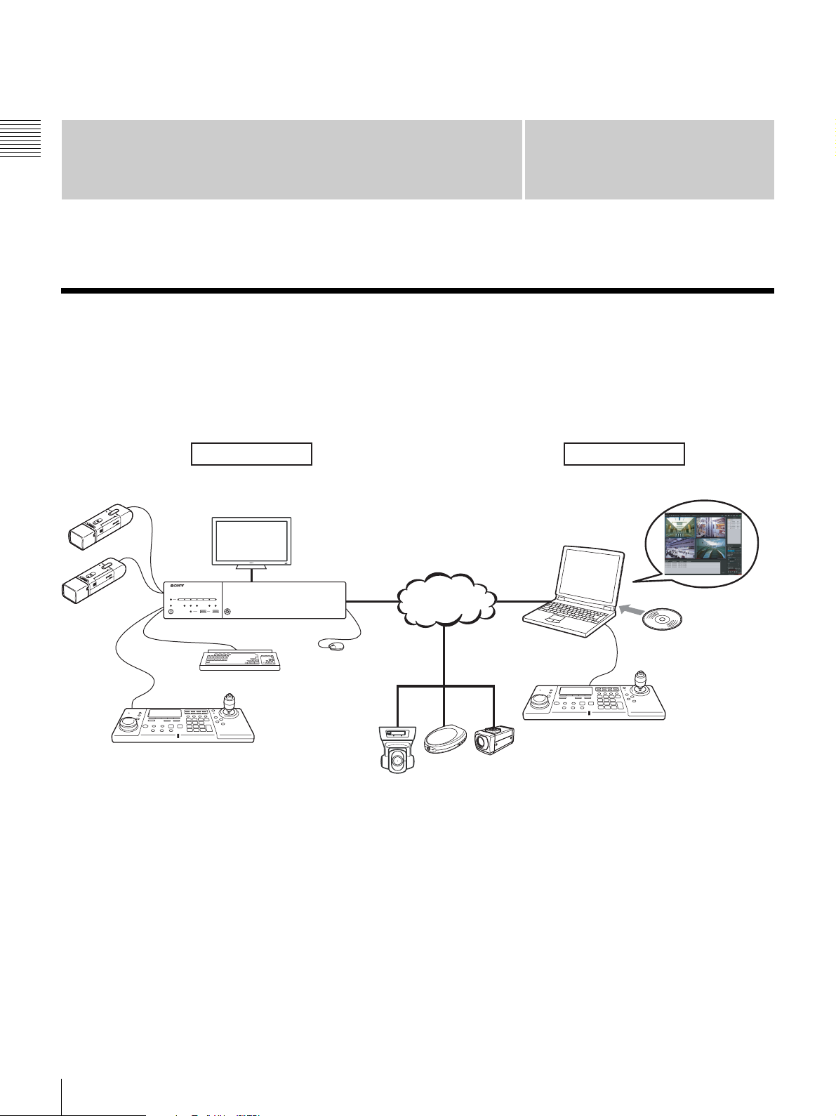
Overview
The NSR-500 series is a network surveillance server for network cameras. The NSR series allows you to monitor and
record JPEG, MPEG-4, and H.264 images from network cameras via the network. It also allows you to search and play
back recorded images, making the NSR a truly versatile monitoring system.
Machine room Surveillance room
Analog Camera
System Controller
1)
Monitor
Network
NSR-500 Series
Mouse
Keyboard
Surveillance cameras
1) The NSR requires an NSBK-EB05 (optional) expansion.
RealShot Manager Advanced
Client is used for surveillance
and configuration.
Windows PC
System Controller
RealShot Manager Advanced
Client Software
Installing
6
Overview
Page 7

Control compatible cameras from remote
locations
You can pan, tilt, and perform zoom operations of
compatible cameras.
Compatible with analog cameras
You can monitor and record images from analog cameras
by connecting them directly to the unit
1) The NSR requires an NSBK-EB05 (optional) expansion.
1)
.
Slim type (2U), space-saving 19-inch rack
mounting model
With a purpose-built rack mounting kit, the unit can be
installed in a standard universal pitch EIA 19-inch rack.
For details on the rack mounting kit, contact your Sony
dealer.
High reliability
The NSR supports redundant configurations such as RAID
1)
5
and performs with high reliability. In a RAID 5
configuration, for example, the system can continue
functioning even if one of the hard disks develops a
malfunction. The NSR also supports uninterruptible power
supplies (UPS)
2)
, making them extremely reliable
systems.
1) RAID 5 is a system for dividing and storing data and parity
(error correcting codes) onto more than one hard disk drive.
Although this system allows continued operation should one
of the hard disks malfunction, it does not guarantee restoration
of lost data. In addition, due to high internal processing loads
during reconstruction after you replace the malfunctioned
hard disk, the unit may not be able to record images at the
configured recording rate while reconstruction is in progress.
2) If the power turns off suddenly during operation, the data may
be corrupted.
Chapter 1 Introduction
Protect data from power interruptions
If the power supply is interrupted while the unit is in
operation, data may be damaged. We recommend using an
uninterruptible power supply (UPS).
Other features
• Custom layout support allows you to display images in a
variety of different layouts in addition to standard 2 × 2
and 3 × 3 layouts.
• The NSR is capable of manual, scheduled, and alarm
recording, among others.
• Run searches for recorded images by camera name, date,
alarm, and other methods.
• Audio recording and playback
1)
are also supported from
compatible cameras.
• If a video loss occurs due to the network connection
being disrupted or an abnormal shutdown occurring,
video can be recorded to the camera’s Edge Storage,
allowing you to retrieve the data later after the system is
restored.
1) Optional audio amplifiers or speakers are required.
Overview
7
Page 8
Features and Functions
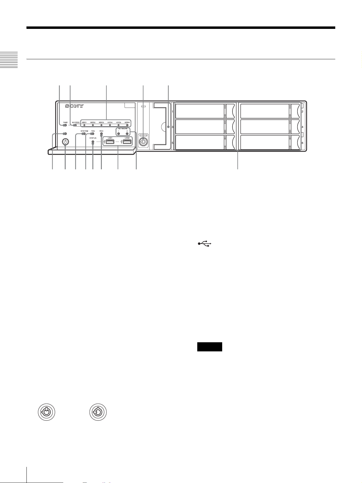
Front (When the Front Cover and the HDD Cover are Opened)
Chapter 1 Introduction
12 3 4 5
qd qs 90qaqf
A RAID LED
Lights green when the RAID configuration is
functioning properly.
Lights red if a fatal problem exists with the RAID due
to an internal HDD failure, for example.
Lights amber if the RAID is degraded or rebuilding.
B ACCESS LED
Blinks green when the HDDs are accessed.
C HDD LEDs (1 to 6)
Light green when the internal hard disk drives are
functioning properly.
Light red when failures or other problem occurs.
Also, light amber during the rebuilding of RAID.
D Lock
Use this in conjunction with the supplied HDD cover
key to lock the HDD cover.
When the HDD cover is locked, you cannot remove it.
The fan unit is also locked when the HDD cover is
locked.
When attaching the HDD cover, make sure the lock is
the unlocked state before you attach the cover.
You can distinguish the locked position from the
unlocked position by looking at the lock, as illustrated
below.
The HDD cover is
locked
E Fan unit
For details on maintenance, contact your Sony dealer.
The HDD cover is
unlocked
768
F HDDs
For details on maintenance, contact your Sony dealer.
G NETWORK LEDs (1 and 2)
Light green when there is a link to the network.
Blink amber when the network is being accessed.
H USB connectors (1 and 2)
Use these connectors to connect a USB mouse, USB
keyboard, USB flash memory device, USB CD/DVD
drive, or system controller (RM-NS1000) to the unit.
I REC LED
Lights red when recording images.
J STATUS LED
Indicates the recognition status of USB flash memory
devices.
If a device is recognized, this lights green.
If a device is not recognized, this lights red.
Caution
Do not remove the USB flash memory device while
the LED is blinking.
K FAN LED
Lights green when the internal fan is functioning
properly. Lights red when a fan failure occurs.
L SYSTEM LED
Blinks green while the unit is starting up and then
changes to always on when the unit has started.
During operation, this LED is lit green when the
system is functioning normally. When a system error
or other problem occurs, it lights red.
If this LED is lit red, contact your Sony dealer.
8
Features and Functions
Page 9
M Power switch
Press this to turn on the unit.
If you press the power switch during operation, the
POWER LED blinks green for up to 3 seconds.
Pressing the power switch again during this time turns
off the unit.
If 3 seconds elapse without the power switch being
pressed while the POWER LED is blinking, the unit
does not turn off and operation continues.
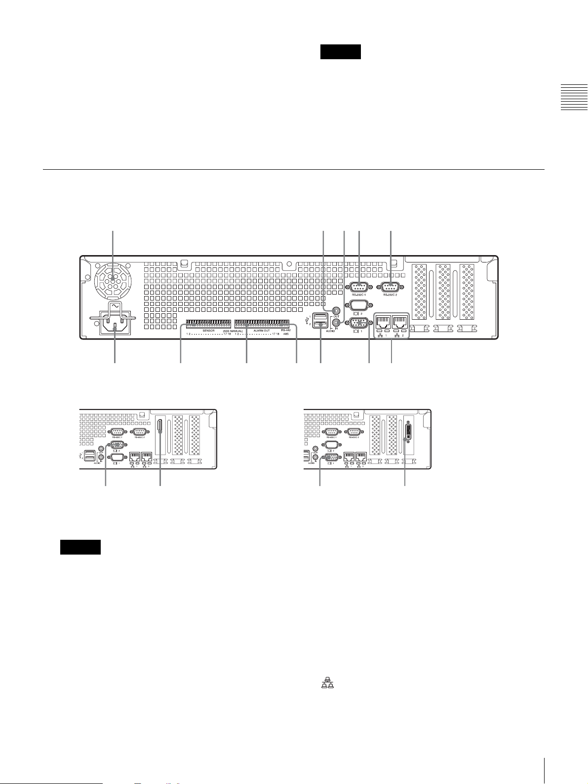
Rear
NSR-500
12345
Caution
Pressing and holding down the power switch
(approximately 5 seconds) turns off the unit forcefully.
N POWER LED
Lights green when the unit is turned on.
If you press the power switch during operation, the
POWER LED blinks green for up to 3 seconds.
Chapter 1 Introduction
qs 90qa
When NSBK-DH05 (optional) is mounted When NSBK-EB05 (optional) is mounted
qd7
A Fan
Caution
Take care not to obstruct the fan grille. If the grille is
obstructed, heat may build up in the unit, leading to
damage and/or fire.
B AUDIO OUT (line output) connector (stereo)
Use these connectors to output audio to a peripheral
audio device.
C AUDIO IN (microphone input) connector (used for
future expansion)
Use this connector to input audio from a peripheral
audio device, such as a microphone.
Plug-In Power microphones are supported.
D RS-232C 1 (UPS) connector
Use this connector to connect the control line of the
uninterruptible power supply (UPS).
E RS-232C 2 connector
Use this connector to connect analog cameras via the
analog camera input cable.
This connector cannot be used at the same time as the
I RS-422/485 connector.
For pin assignment details and wiring diagrams for
sensor inputs, refer to the Installation Manual
(separate document).
F LAN connectors (1 and 2)
Use these connectors to connect 10Base-T, 100BaseTX, or 1000Base-T network cables.
LAN1: Network cameras
768
qf7
1)
Features and Functions
9
Page 10

LAN2: Network cameras1) (LAN2 can only be used
when using a different segment from LAN1.)
1) Connect remote clients to the network specified with the [Network
Interface for Remote Client] setting (either LAN1 or LAN2) in the
Server Configuration screen. For details, see “Configuring Settings
Related to Servers” (page 18).
Chapter 1 Introduction
Caution
• Do not configure LAN connectors 1 and 2 to the
same network segment.
• For details on using iSCSI storage, contact your
Sony dealer.
CAUTION
• For safety, do not connect the connector for
peripheral device wiring that might have excessive
voltage to the following ports.
- LAN1 connector
- LAN2 connector
• Follow the instructions for the above ports.
• When you connect the LAN cable of the unit to
peripheral device, use a shielded-type cable to
prevent malfunction due to radiation noise.
G Monitor connectors (1 and 2)
Use this connector to connect a monitor that supports
analog RGB input.
For connection details and wiring diagrams for sensor
inputs, refer to the Installation Manual (separate
document).
L Power supply connector
Use this connector to connect the power cord.
M HDMI monitor connector
Use this connector to connect a monitor that supports
HDMI input.
Monitor connector 2 and the HDMI monitor connector
cannot be used at the same time.
This connector can only be used when an NSBKDH05 (optional) is mounted.
N Analog camera cable input connector
Use this connector to connect the analog camera input
cable.
This connector can only be used when an NSBK-EB05
(optional) is mounted.
CAUTION
When you connect the analog camera input cable of
the unit to peripheral device, use the supplied cable to
prevent malfunction due to radiation noise.
Caution
If the optional NSBK-DH05 is installed, monitor
connector 1 will not be available for use. Only monitor
connector 2 will be available. Monitor connector 2 and
the HDMI monitor connector cannot be used at the
same time.
H USB connectors (1 and 2)
Use these connectors to connect a USB mouse, USB
keyboard, USB flash memory device, USB CD/DVD
drive, or system controller (RM-NS1000) to the unit.
I RS-422/485 connector
Use this connector to connect analog cameras via the
analog camera input cable.
This connector cannot be used at the same time as the
E RS-232C 2 connector.
For pin assignment details and wiring diagrams for
sensor inputs, refer to the Installation Manual
(separate document).
J ALARM OUT (alarm output) connector
Use this connector to connect the alarm output lines.
For connection details and a wiring diagram for alarm
output, refer to the Installation Manual (separate
document).
K SENSOR (sensor input) connector
Use this connector to connect the sensor input lines.
10
Features and Functions
Page 11

System Requirements
The hardware required in order to use this unit are as
follows.
- We do not recommend using a USB hub.
Chapter 1 Introduction
• Monitor
• Sony network cameras2) or Sony analog cameras3)
• USB keyboard
•USB mouse
1)
4)
5)
•Network hub
• 1000Base-T/100Base-TX/10Base-T cable
• USB flash memory device
• USB CD/DVD drive
1) Computer displays that accept RGB input are supported.
The supported resolutions are as follows.
- Full High-Definition (1,920 × 1,080)
- WUXGA (1,920 × 1,200)
- Full Wide XGA (1,360 × 768)
- UXGA (1,600 × 1,200)
- SXGA (1,280 × 1,024)
- XGA (1,024 × 768)
When NSBK-DH05 (optional) is mounted
HDMI-compatible devices and computer displays that accept
RGB input are supported.
The supported resolutions are as follows.
- Full High-Definition (1,920 × 1,080)
- WUXGA (1,920 × 1,200)
- Full Wide XGA (1,360 × 768)
- UXGA (1,600 × 1,200)
- SXGA (1,280 × 1,024)
- XGA (1,024 × 768)
However, WUXGA is not supported on HDMI-compatible
devices.
2) Contact your dealer for details about compatible Sony
network cameras.
3) The NSR requires an NSBK-EB05 (optional) expansion.
4) Use a USB keyboard with a cable. However, keys other than
the standard may not function. Wireless or infrared USB
keyboards may also not function properly.
5) Use a USB mouse with a cable. Wireless or infrared USB
mice may not function properly. Functions such as threebutton and wheel operations may also function improperly.
6) Required when backing up system information such as logs.
- This unit supports USB 2.0, Mass Storage class devices.
However, it does not support USB 2.0, Mass Storage class
HDDs. Be aware that errors may still occur when writing
data to a USB 2.0, Mass Storage class memory device,
depending on the type of device used. If errors occur when
writing data, use a USB flash memory device of a different
type. Only FAT-format USB flash memory devices are
supported.
7) The following restrictions apply.
- Supported media: CD-R, CD-RW, DVD-R, DVD+R,
DVD+R DL
- Format: ISO 9660 format (RockRidgeExtension/
JolietExtension)
- Use blank media or media that has previously been written
on using the NSR-500 series.
- Media that has been written on using equipment other than
the NSR-500 series is not supported.
- USB 1.1/2.0 supported.
- We do not recommend using USB bus power. Use an AC
power supply.
6)
7)
System Requirements
11
Page 12
Administration Menu
Chapter 2
Administration Menu
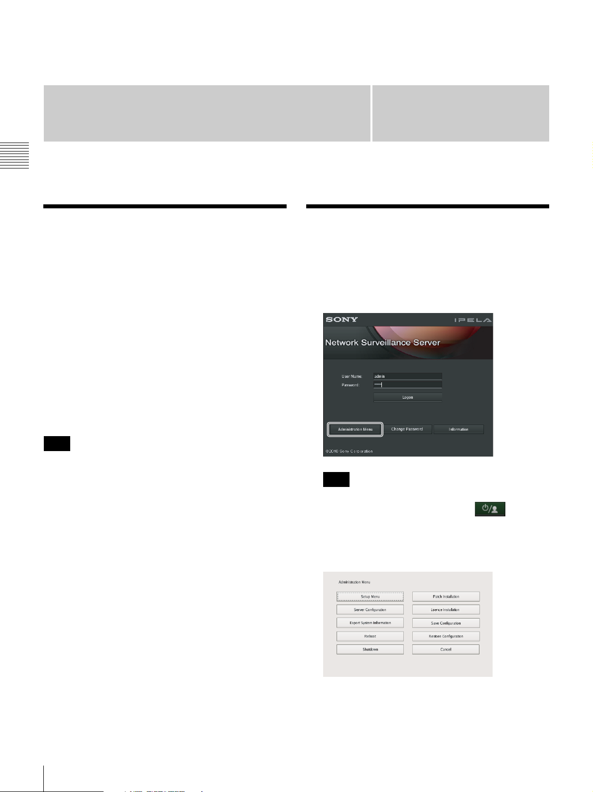
Overview
The Administration Menu allows you to change settings
that were configured with the Setup Wizard when you
turned on the NSR for the first time, and also allows you to
perform configurations and operations related to the
server.
This chapter describes the following configurations and
operations for the Administration Menu.
• “Displaying the Administration Menu” (page 12)
• “Changing Initial Settings with the Setup Menu”
(page 13)
• “Configuring Settings Related to Servers” (page 18)
• “Installing Patch Files” (page 20)
• “Saving and Restoring Configuration Data” (page 21)
• “Exporting System Information” (page 23)
Chapter
2
Displaying the Administration Menu
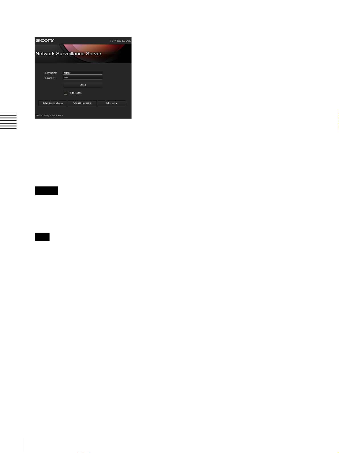
1
Enter the user name and password in the logon screen,
and click [Administration Menu].
Note
For details on restart and shutdown procedures, see
Chapter 3 “Shutting Down and Restarting the NSR”
(page 32).
Note
If you are already logged on to the NSR, you can
display the logon screen by clicking at the top
right of the Main screen and logging off from the
dialog box that appears.
The Administration Menu screen appears.
12
Overview / Displaying the Administration Menu
Page 13
Changing Initial Settings
Details on Setting Items
with the Setup Menu
Use the Setup Menu to change settings that were
configured with the Setup Wizard when you turned on the
NSR for the first time.
Displaying Setup Menu
1
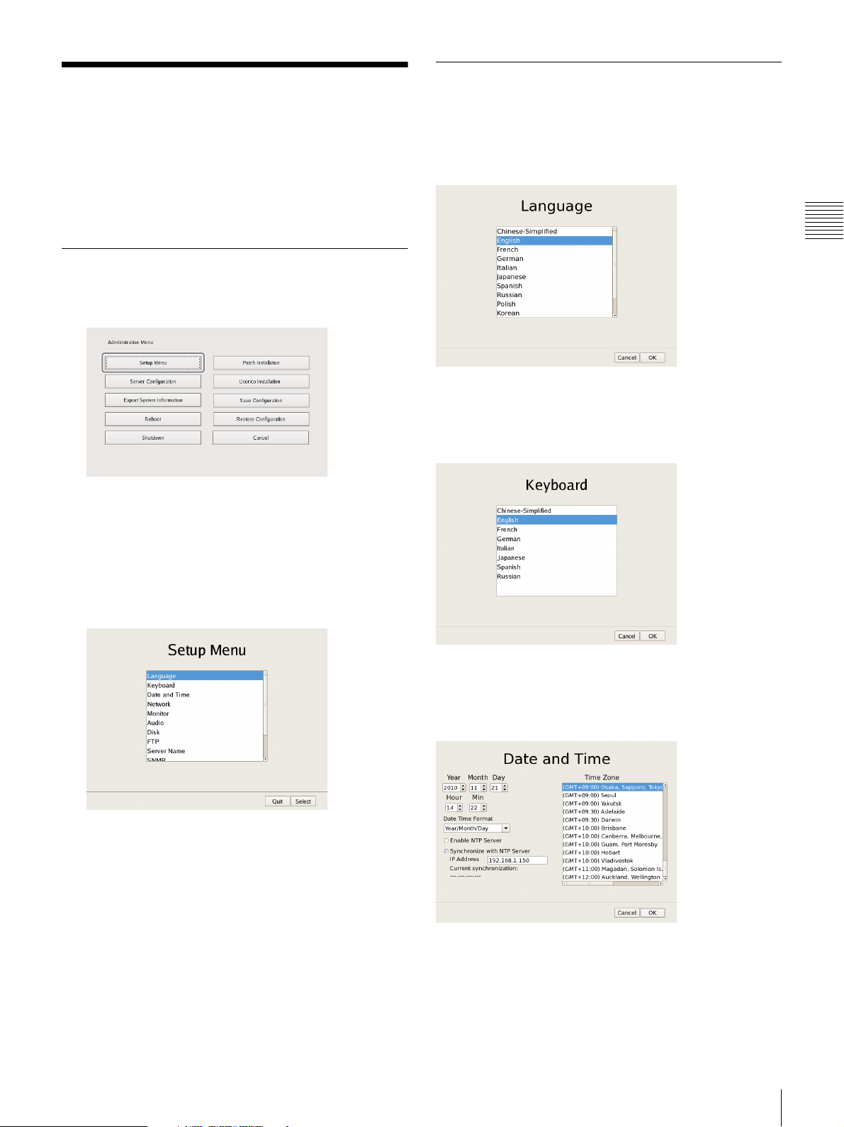
Click [Setup Menu] in the Administration Menu.
The menu items of the Administration Menu differ
depending on the server and clients.
Setting Items of Language Screen
Select the language to display on the screens, and click
[OK].
Chapter 2
Administration Menu
Setting Items of Keyboard Screen
Select the language of the USB keyboard connected to
NSR, and click [OK].
The Setup Menu appears.
2
Select the item you want to configure, and click
[Select].
The screen corresponding to the item appears.
Setting Items of Date and Time Screen
Configure the date and time of the equipment, and click
[OK].
Year/Month/Day
Enter the date.
Hour/Min
Enter the time.
Changing Initial Settings with the Setup Menu
13
Page 14
Date Time Format
Select the format for the date and time.
Enable NTP Server
Select the check box to enable the NTP server of NSR.
LAN2: Network cameras1) (LAN2 can only be used when
using a different segment from LAN1.)
1) Connect remote clients to the network specified with the [Network
Interface for Remote Client] setting (either LAN1 or LAN2) in the Server
Configuration screen. For details on the Server Configuration screen, see
“Configuring Settings Related to Servers” (page 18).
Caution
When the NTP server of NSR is enabled, enable
[Synchronize with NTP Server] as well, and configure
settings to obtain clock information from other NTP
Chapter 2
servers. If you do not configure the settings, the clock may
deviate dramatically.
Synchronize with NTP Server
Administration Menu
Select the check box to obtain the current time from
another NTP server.
IP Address
Enter the IP address of the NTP server from which to
obtain the information.
Current Synchronization
This displays the IP address of the NTP server from
which the current information is being obtained.
Time Zone
Select the region to configure the date and time.
Note
There is no setting for enabling or disabling daylight
saving time. If you select a time zone in which daylight
saving time is observed, the clock is adjusted
automatically for daylight saving time.
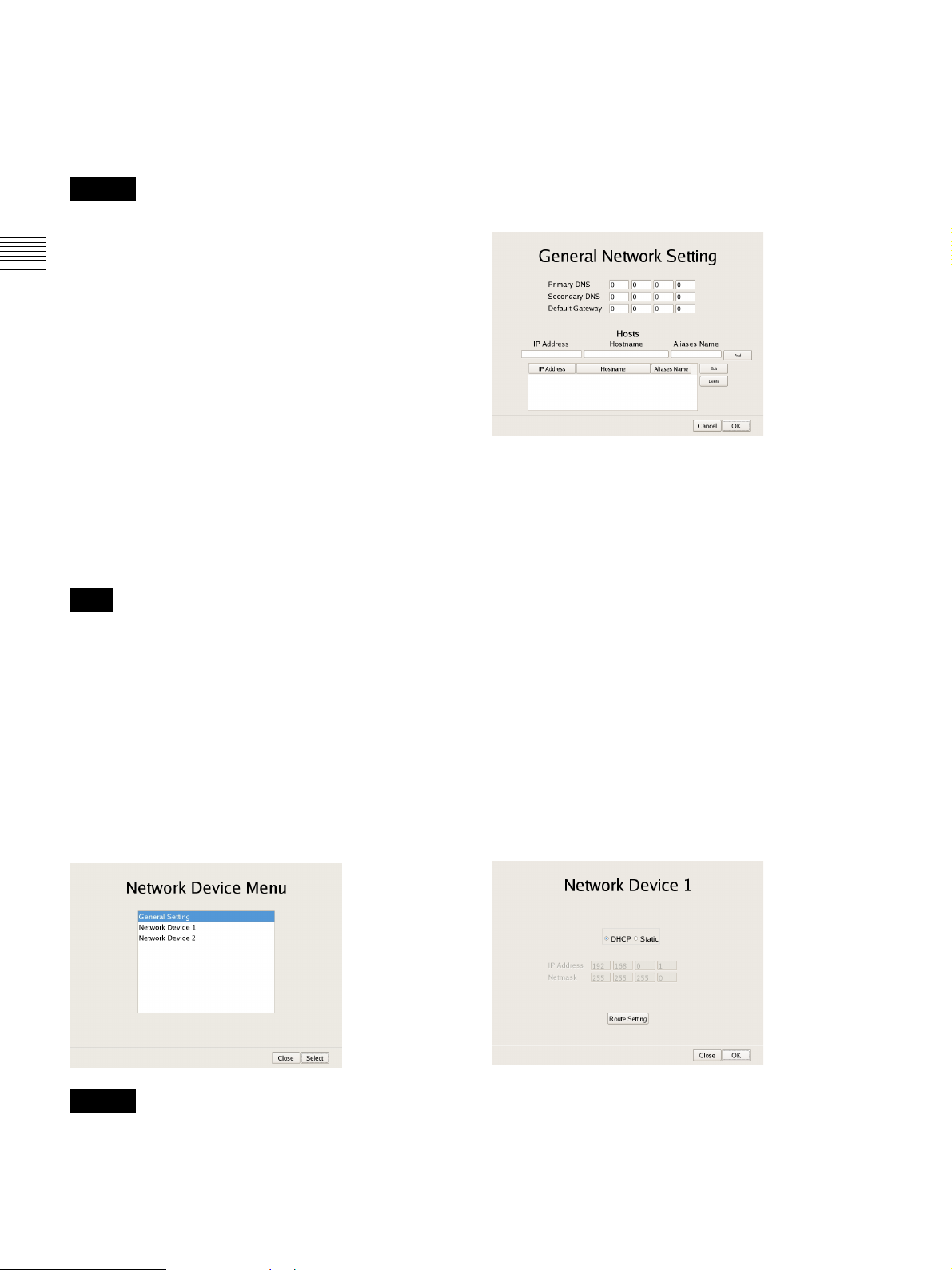
xSetting Items of General Network Screen
Configure each item, and click [OK].
Primary DNS
Enter the IP address for the primary DNS (Domain Name
Server).
Do not enter this if there is no primary DNS, or if it is not
required.
Secondary DNS
Enter the IP address for the secondary DNS. Do not enter
this if there is no secondary DNS, or if it is not required.
Default Gateway
Enter the IP address for the default gateway. Do not enter
this is if there is only a local network or there is no need to
connect to another network.
Setting Items of Network Device Menu
Screen
The network settings consist of “General Network” for
setting general settings, and “Network Device 1 to 2” for
setting LAN connectors.
Select the network you want to configure, and click [OK].
Caution
Connect the following devices to the LAN connectors.
LAN1: Network camera
1)
Hosts
If host name registration is necessary, enter a combination
of the IP address and host name, and click [Add] to add the
host to the list.
xSetting Items of Network Device 1 to 2
Configure each item, and click [OK].
Configure the settings as follows in accordance with your
environment.
14
Changing Initial Settings with the Setup Menu
Page 15
To use a DHCP to obtain the address setting automatically:
Select [DHCP].
To configure the address setting manually:
1 Click [Static].
2 Enter the following address.
IP Address
Enter the IP address.
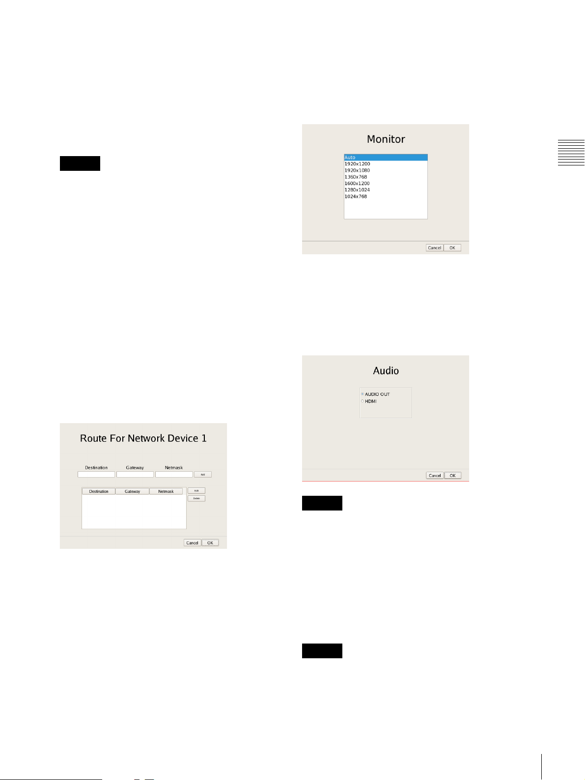
Setting Items of Monitor Screen
Select the resolution of the monitor connected to the unit,
and click [OK].
If you select [Auto], the maximum resolution of the
connected monitor will be detected and selected
automatically.
Caution
• Before you enter the IP address, make sure there is
no machine that uses the same value on the same
network. Even if a machine that uses the same value
does exist, an error message will not be displayed.
However, be careful because more than one machine
using the same value will result in incorrect
operation.
• Do not set an IP address that is prohibited under the
IP address assignment rules.
Example: 224.0.0.0 to 255.255.255.255
0.0.0.0
127.0.0.1, etc.
Netmask
Enter the subnet mask.
Route Setting
Click this when you need to configure the route to
another network.
Configure the settings as follows on the Route For
Network Device 1 screen that appears.
Chapter 2
Administration Menu
Setting Items of Audio Screen
Select the audio connector you want to use, and click
[OK].
When using audio output from an HDMI monitor, select
[HDMI]. ([HDMI] can only be selected when an optional
NSBK-DH05 is installed.)
1 Enter the address, gateway, and netmask of the
other network to which to connect, and click [Add]
to add the network to the list.
For details, contact the administrator of the network
to which you will connect.
2 Click [OK].
Caution
When removing an NSBK-DH05 from the main unit, be
sure to check that AUDIO OUT is in use. If the
NSBK-DH05 is removed from the main unit while
[HDMI] is selected, audio will not be output from AUDIO
OUT until it is reselected. In such cases, reselect [AUDIO
OUT] in the Audio screen.
Setting Items of Disk Screen
Configure iSCSI settings.
Caution
Contact your Sony dealer when using iSCSI.
Changing Initial Settings with the Setup Menu
15
Page 16
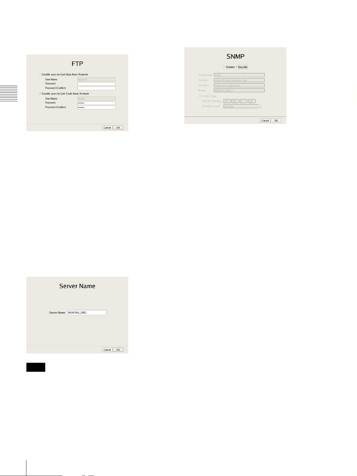
Setting Items of FTP Screen
Configure each of the items when you want to enable the
FTP server, and click [OK].
Chapter 2
Administration Menu
Enable user to Get Data from Remote
This function is used for service and maintenance.
Enable user to Get Tools from Remote
Select the check box to enable remote client downloading
of tools, operating manuals, and other documents using
FTP.
This is enabled under default settings.
User Name
This displays the user name. The user name is
“ftptool.”
It cannot be changed.
Password
Enter the password. The default password is “ftptool.”
Setting Items of Server Name Screen
Enter the server name of NSR, and click [OK].
Setting Items of SNMP Screen
Configure each item related to SNMP, and click [OK].
Enable
Select this to enable the SNMP agent function.
Disable
Select this to disable the SNMP agent function.
Community
Enter the SNMP community name.
Contact
Enter the contact.
Normally, enter the mail address of the system
administrator.
Location
Enter the installation location of NSR.
Name
Enter the name of the NSR unit.
Enable Trap
Select this to enable SNMP trap transmission.
Notes
• If you do not set a server name, a default name (e.g.,
NSR500_DB12) to which the last four digits of this
unit’s LAN1 MAC address is appended is set.
• Do not use spaces when entering the server name.
Sink IP Address
Enter the destination IP address for SNMP traps.
Severity Level
Select the severity level for SNMP trap transmission.
An SNMP trap will be sent when severity levels meet or
exceed this setting.
For details on SNMP traps, contact your Sony dealer.
16
Changing Initial Settings with the Setup Menu
Page 17
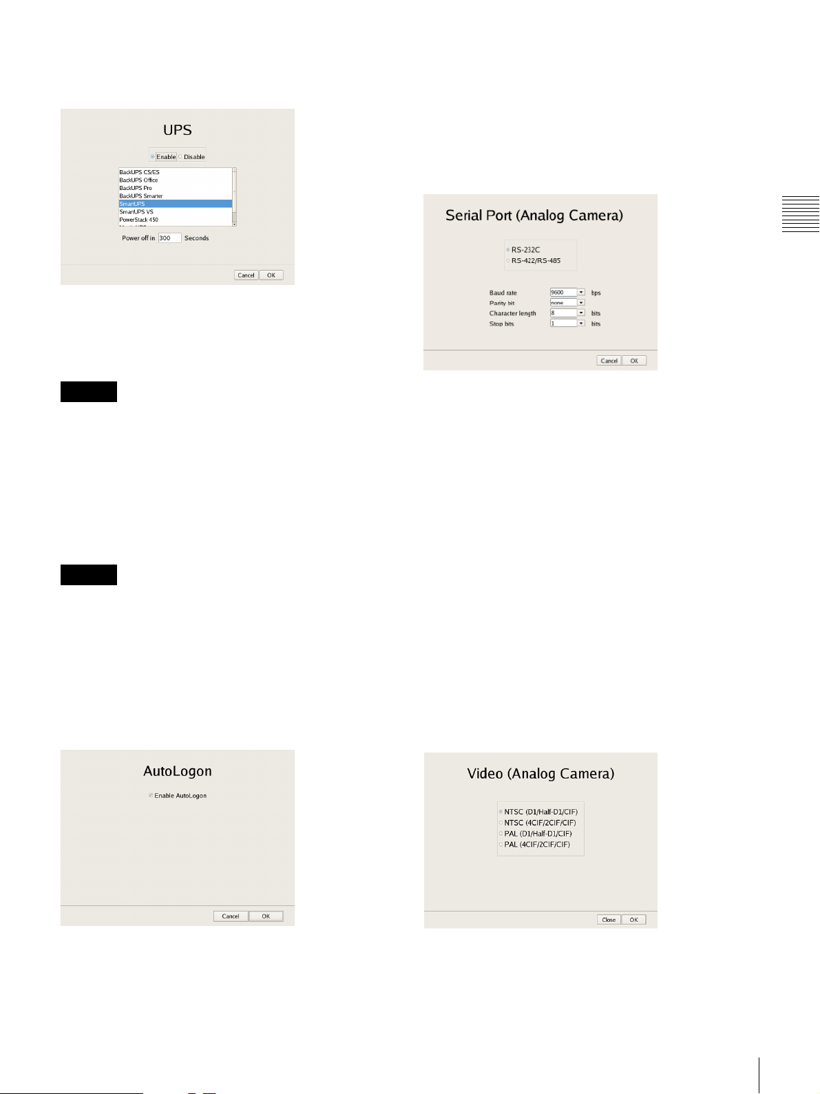
Setting Items of UPS Screen
Configure settings related to UPS, and click [OK].
Enable
Select this when using a UPS.
If this is selected, select the type of UPS to be used from a
list of UPS.
Setting Items of Serial Port (Analog
Camera) Screen
Configure settings related to the analog camera
connection.
Configure each item, and click [OK].
(This screen only appears when an optional NSBK-EB05
is installed.)
Chapter 2
Administration Menu
Caution
If the power turns off suddenly during operation, the data
may be corrupted.
Disable
Select this when not using a UPS.
Power off in XXX Seconds
Enter the time from when a power cut is detected until
shutdown to start.
Caution
For details on automatic startup after power is restored,
contact your dealer.
Setting Items of Auto Logon Screen
When you want to enable the auto logon function, select
the [Enable Auto Logon] check box, and click [OK].
For details on the auto logon function, refer to “Logging
On to the NSR” (page 25).
Serial standard (RS-485, RS-422, RS-232C)
Select the serial standard for connecting to the analog
camera you want to control.
Baud rate
Select the communication baud rate.
Parity bit
Select the parity bit.
Character length
Select the character length.
Stop bits
Select the stop bits.
Setting Items of Video (Analog Camera)
Screen
Select the video format for the analog camera to be
connected, and click [OK].
(This screen only appears when an optional NSBK-EB05
is installed.)
Changing Initial Settings with the Setup Menu
17
Page 18
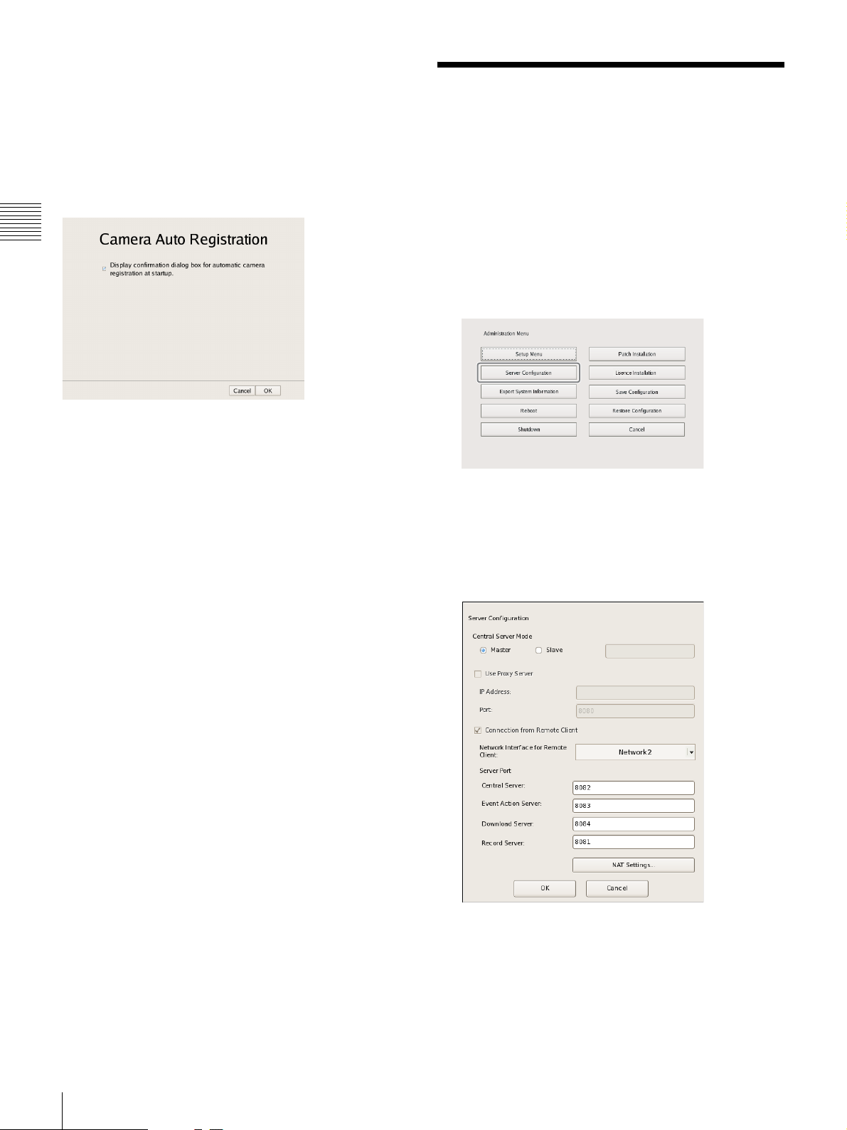
Setting Items of Camera Auto Registration
Screen
When you want to enable the camera auto registration
function, select the [Display confirmation dialog box for
automatic camera registration at startup] check box and
click [OK]. If you select this check box, the Camera
Automatic Registration screen appears when the unit starts
up.
Chapter 2
Administration Menu
Configuring Settings Related to Servers
Configure these settings when, for example, you want to
change the network settings to match the network
environment of the users, or you want to centralize user
administration when using multiple NSR and RealShot
Manager Advanced together.
1
Click [Server Configuration] in the Administration
Menu.
The menu items of the Administration Menu differ
depending on the server and clients.
The Server Configuration screen appears.
2
Configure each item, and click [OK].
18
Configuring Settings Related to Servers
Central Server Mode
Set this if you want to manage multiple NSRs and
RealShot Manager Advanced (Server) as one
1)
system
Manager Advanced (Client).
, or you want to connect from RealShot
Page 19
You can set one master server for uniformly managing
users in the system, and multiple slave servers.
1) This is for when you want to perform common user
management with multiple servers, or when you want to
connect from RealShot Manager Advanced (Client).
Select [Master] or [Slave].
If you select [Slave], enter the master server address to
which to connect.
If a server is changed from master to slave, the user
information that was configured locally is discarded
and the user information of the master is used.
If you want to change this setting, basically change it
immediately after installation.
If you change this setting, restart the system.
Use Proxy Server
Select the check box when using a proxy server for
connecting to the slave servers and master server of the
central server.
IP Address
Enter the IP address for the proxy server.
Port
Enter the port number for the proxy server.
Connection from Remote Client
Select the check box to connect from a remote client.
Network Interface for Remote Client
Select the network to use for the connecting with
remote client.
Server Port
Central Server
Configure the port number for the central server.
• When the central server mode or the server port is
changed, a message appears and the system restarts.
• If you changed the network interface for the remote
client, you must restart the system. When changing the
server mode, be sure to change the network interface
setting and restart the system beforehand.
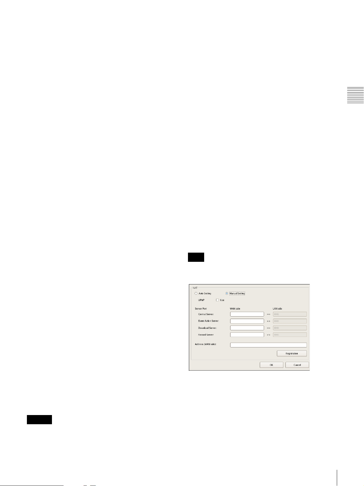
Setting Items of NAT Setting Dialog Box
Configure port forwarding settings for broadband routers.
If the router supports the UPnP function, you can use the
UPnP function to configure the router settings.
• If you select [Auto Setting], all of the setting items will
be configured automatically via UPnP. Select [Manual
Setting] if you want to specify port numbers manually.
• Regardless of whether [Auto Setting] or [Manual
Setting] is selected, router configuration is not necessary
if the UPnP function is used.
• If you select [Manual Setting] and do not use the UPnP
function, be sure to configure settings on the router side,
and enter those same settings for the appropriate items in
this dialog box.
• If you changed the network interface for the remote
client, you must restart the system. When changing the
server mode, be sure to change the network interface
setting and restart the system beforehand.
This dialog box appears when you select [NAT Setting] on
the Server Configuration screen (page 18). After
configuring each setting, click [OK].
Note
These settings are not required if you do not intend to
connect from clients on external networks.
Chapter 2
Administration Menu
Event Action Server
Configure the port number for the event action
server.
Download Server
Configure the port number for the download server.
Record Server
Configure the port number for the record server.
NAT Setting
Displays the NAT Setting dialog box (page 19).
Configure these settings when you want to connect
to the server via an Internet connection, for
example, from a client connected to an external
network using a broadband router.
Caution
• When changing to [Slave], register a user other than
“admin” on the master server, and use that user. The user
level for the user must be “Level 5”.
Auto Setting
Automatically configures settings for the router.
UPnP
If you select [Auto Setting], the [Use] check box will
be selected automatically.
Configuring Settings Related to Servers
19
Page 20
Manual Setting
Specify port numbers and a global IP address.
When you select this option, enter values for each setting
item under [Server Port] and [Address (WAN side)].
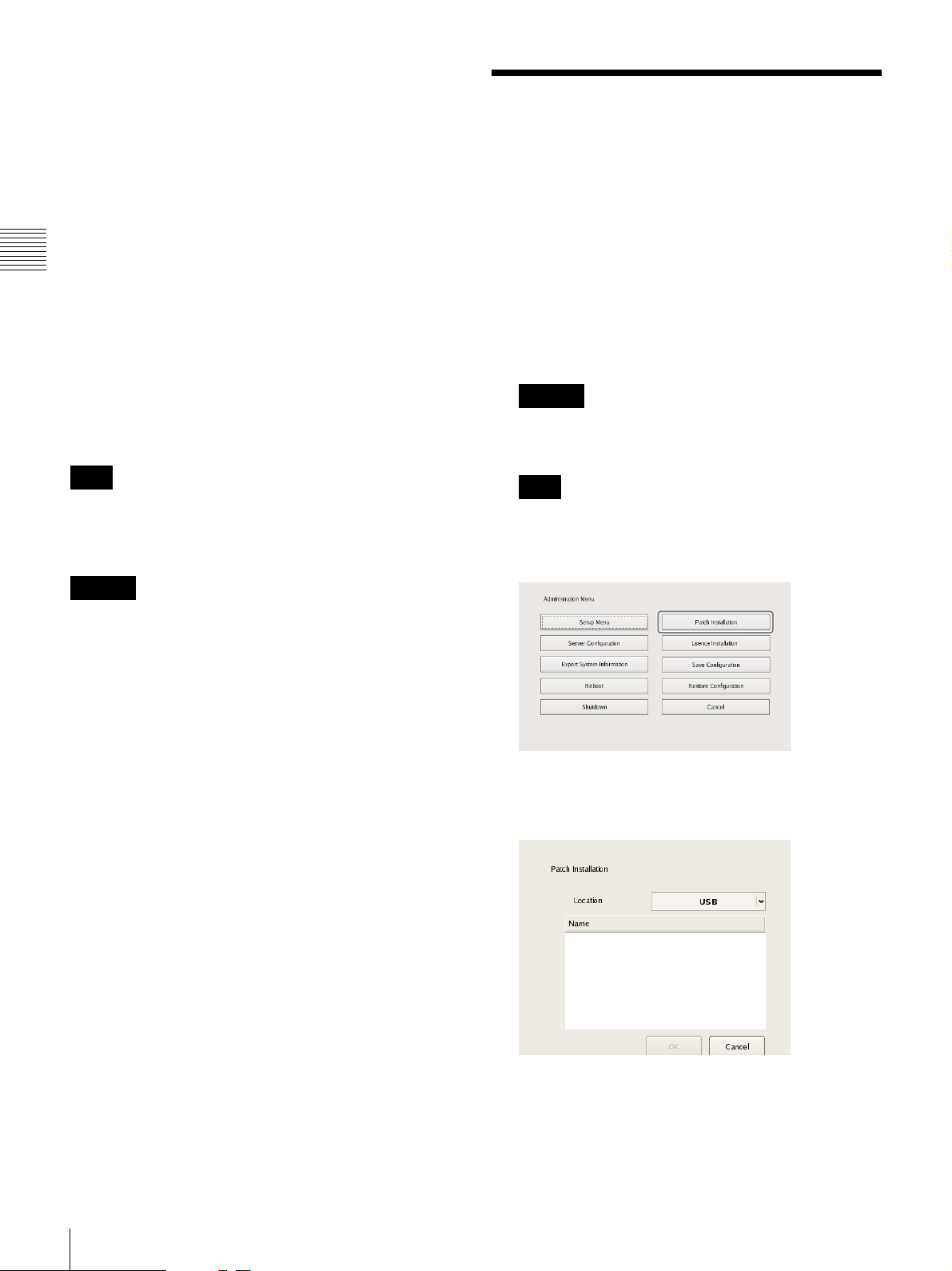
Installing Patch Files
UPnP
To use the UPnP function, select the check box next to
[Use].
Server Port
Enter the WAN-side port number of the Central Server,
Chapter 2
Event Action Server, Download Server, and Record
Server.
The LAN-side port numbers are only for display and
cannot be configured.
Administration Menu
Address (WAN side)
Enter a global IP address.
Registration
Registers your settings.
Note
When connecting from a client, the [Address] and [Central
Server] under [Server Port] configured in the above will be
used as the client logon server.
Caution
• To ensure Internet (WAN side) security, be sure to use
the firewall function on your router or similar device,
and confirm that the security for the configured port is
enabled.
• If security is not enabled via the router or similar device,
there is a risk of the NSR being accessed by
unauthorized users via the WAN side ports. To maintain
security, change the password regularly and configure
other related settings.
password, refer to “Changing the Password” (page 30).
• If unauthorized users log onto NSR, there is a risk of the
following.
– NSR settings may be changed.
– Images from cameras and recorded images may be
• Depending on your router and operating environment,
connection from an external network may be disabled.
1)
3)
viewed and operated.
2)
For details on changing the
Patch files distributed by Sony can be installed on the
NSR.
A patch file is distributed when, for example, cameras
supported by the NSR are added to the lineup and when
new functions are added. We recommend installing patch
files so that you can operate the unit with the latest
software.
For details on patch file distribution, contact your Sony
dealer.
1
Copy the patch file onto a USB flash memory device.
Caution
Do not change the file name or other aspects of the
patch file.
Note
The USB flash memory only supports FAT32 format.
2
Click [Patch Installation] in the Administration Menu.
The Patch Installation screen appears.
3
Select the media on which the patch file is stored.
1) For details on router security settings, refer to the operating
instructions for the routers, or contact the manufacturer of
each router.
2) Changing the password does not guarantee prevention of log
on by unauthorized users.
3) Sony Corporation is not liable for any loss of profits incurred
by the customer as a result of such occurrences. The customer
is responsible for configuring appropriate settings and
measures.
20
Installing Patch Files
A list of patch file names appears.
4
Confirm a patch file name, and click [OK].
A confirmation message appears.
Page 21
5
Confirm the content of the message, and click [Yes].
Caution
The NSR will automatically restart after installation of
certain patch files. A confirmation screen will appear
if restart is necessary. If you cannot stop your current
operations, select [No] to cancel installation, and
perform installation when restarting the NSR will not
be a problem.
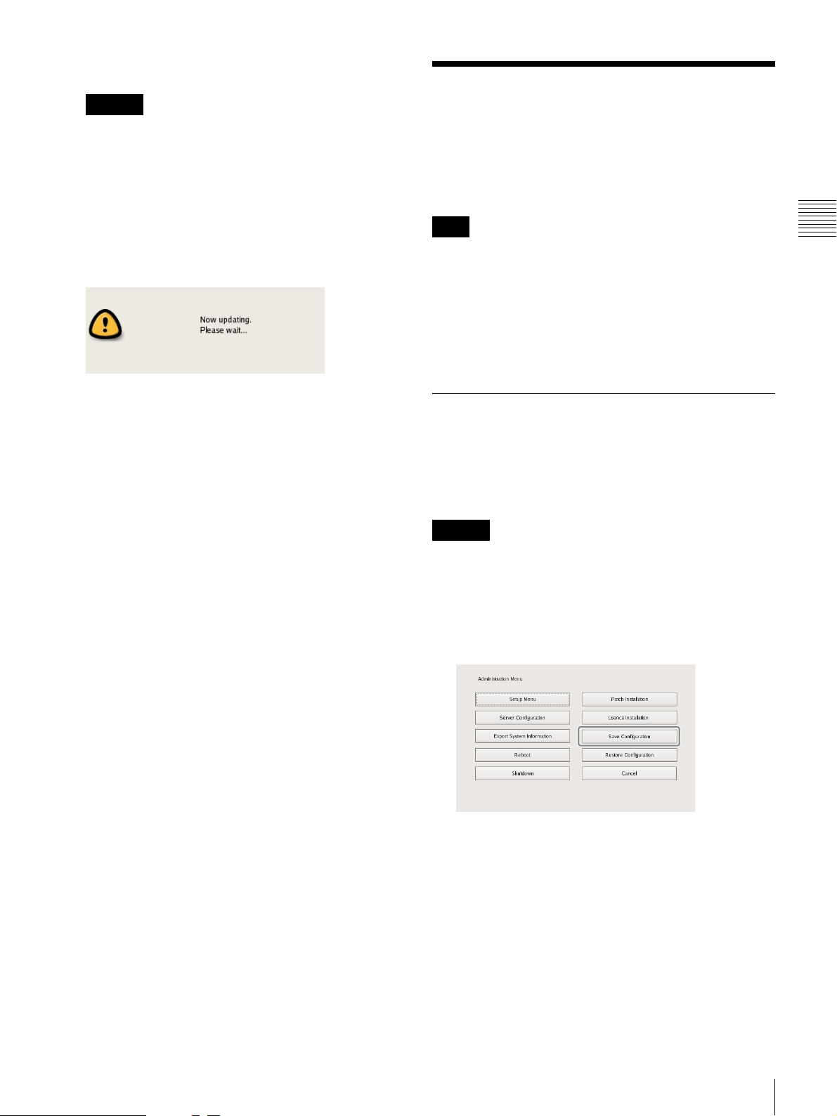
The following screen appears during installation of the
patch file.
When installation is complete, the patch is applied.
After restarting the unit, you can check the software
version under [Information] in the logon screen. Make
sure that the software has been updated to the correct
version.
Saving and Restoring Configuration Data
You can save the configuration data of NSR to external
media, and restore saved configuration data.
Note
Configuration data consists of configurations for all NSR
settings. You can quickly return to a previous
configuration environment by restoring configuration
data.
We recommend saving configuration data regularly each
time you change settings or upgrade the software version,
for example.
Saving Configuration Data
Generally, the settings configured in the Server
Configuration screen in the Administration Menu of the
logon screen and settings configured in the settings screen
after logging on are stored as configuration data.
Chapter 2
Administration Menu
Caution
Note that the following information is not saved.
• Recording records
• Log information
1
Click [Save Configuration] in the Administration
Menu.
The menu items of the Administration Menu differ
depending on the server and clients.
The Save Configuration screen appears.
Saving and Restoring Configuration Data
21
Page 22
Chapter 2
Administration Menu
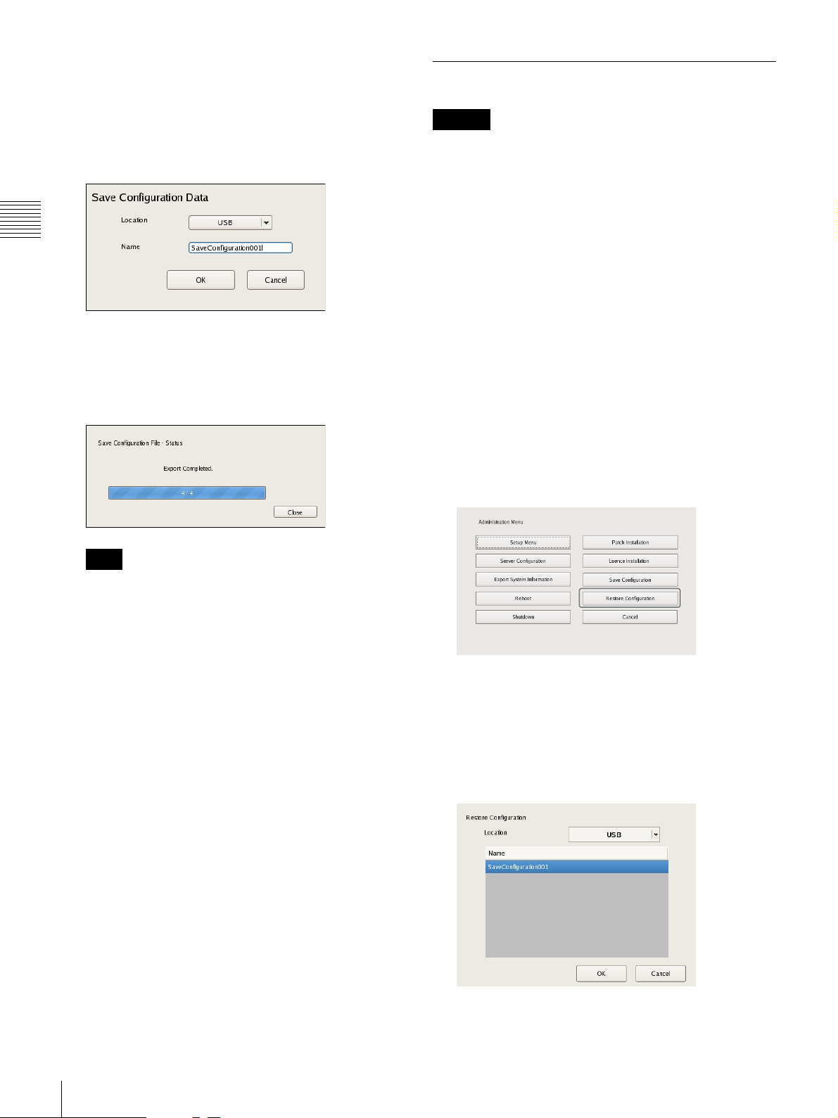
2
Select the media to save the configuration data, enter
the file name for the configuration data, and click
[OK].
You can use alphanumeric characters and some
symbols (periods (.), hyphens (-), underscores (_))
when entering the file name.
A progress bar is displayed during the backing up of
the configuration data, and the configuration data is
saved when the backup is finished.
3
Click [Close].
Restoring Configuration Data
Caution
• Note that the following information is not restored.
– Recording records
– System settings such as network settings and time
information (Items of [Setup Menu] (page 13))
– Logs
• The settings of the external storage itself cannot be
restored, so it is necessary to configure them to the same
settings as those at the time of saving.
• The configuration data cannot be restored if the first two
digits of the current version (e.g.: “a.b” of “a.b.c”
separated by “.”) differ from those at the time of saving
or the model differs.
• When the configuration data is restored, the recording
operation performed up until that point is stopped
automatically. If a recording schedule has been
configured, recording resumes automatically after
restoration. If manual recording was performed, it needs
be started again.
1
Click [Restore Configuration] in the Administration
Menu.
Note
When saving of the configuration data finishes, the
following files are created in the save location.
<Configuration data save name>.item
<Configuration data save name>_db.tar.gz
<Configuration data save name>_img.tar.gz
<Configuration data save name>_os.tar.gz
<Configuration data save name>_preset.tar.gz
Example: When the configuration data is saved under
the name “Configuration001,” files with the names
shown below are created.
Configuration001.item
Configuration001_db.tar.gz
Configuration001_img.tar.gz
Configuration001_os.tar.gz
Configuration001_preset.tar.gz
The menu items of the Administration Menu differ
depending on the server and clients.
The Restore Configuration screen appears.
2
Select the location where the configuration data is
saved and the configuration data, and click [OK].
22
Saving and Restoring Configuration Data
A confirmation message appears to notify you that this
operation requires NSR to be restarted.
Page 23
3
Click [OK].
A confirmation message appears.
4
Click [Yes].
A progress bar appears during restoring, NSR restarts
when the process is finished, and the configuration
data is restored.
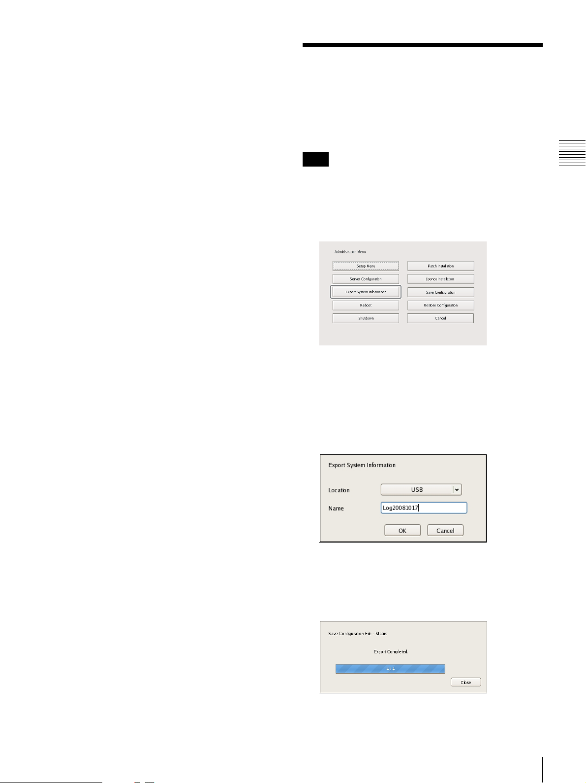
Exporting System Information
You can save NSR system information as files onto
external media.
Note
System information consists of NSR system configuration
information and logs.
1
Click [Export System Information] in the
Administration Menu.
Chapter 2
Administration Menu
The Export System Information screen appears.
2
Select the media on which to save the system
information, enter the file name, and then click [OK].
You can use alphanumeric characters and some
symbols (periods (.), hyphens (-), underscores (_))
when entering the file name.
A progress bar is displayed during exporting of the
system information, and the system information is
saved when exporting is finished.
3
Click [Close].
Exporting System Information
23
Page 24
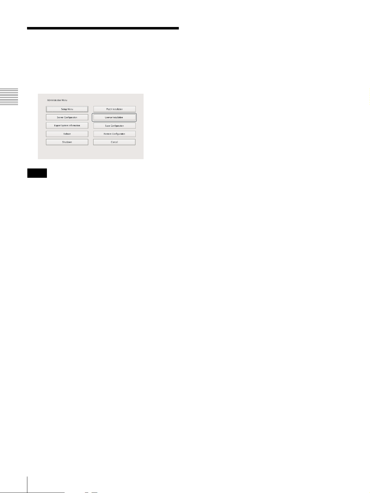
Installing Licenses
You can install a license on the NSR to enable registration
of additional cameras.
You can register up to 16 cameras normally, but this can
be increased to up to 24 cameras.
Chapter 2
Administration Menu
Notes
• For details on licenses, refer to the NSBK-CL05
Installation Guide (PDF).
• For details on acquiring licenses, contact your Sony
dealer.
24
Installing Licenses
Page 25

Basic Operation
Chapter
3
Overview
This chapter describes how to perform the following basic
operations on the NSR, including logging on, using
various windows, changing the password, and turning off
the unit.
• “Logging On to the NSR” (page 25)
• “Basic Window Operations” (page 27)
• “Changing the Password” (page 30)
• “Logging Off” (page 31)
• “Locking the NSR” (page 31)
• “Shutting Down and Restarting the NSR” (page 32)
• “Viewing Version Information” (page 32)
Note
For details on settings related to devices, schedules, sensor
inputs, and alarm outputs, see Chapter 4 “
Settings
for and playing back recorded images, see Chapter 5
“
” (page 33). For details on monitoring and search
Operation and Control
” (page 96).
Application
Logging On to the NSR
Before you can use the NSR, you must first log on.
1
Press the power switch on the front of the NSR to turn
it on.
The startup screen appears, and the progress bar for
software startup appears.
Note
The fan noise may be loud after turning on the unit.
This is not a malfunction.
Chapter 3 Basic Operation
After startup, the logon screen appears.
Overview / Logging On to the NSR
25
Page 26
2
Enter the user name and password, and click [Logon].
Chapter 3 Basic Operation
• If you log on with the [Auto-Logon] check box
selected, the logon screen will not appear the next
time you start the application, and you will be logged
on automatically.
• To change the user that you are logged on as, first
log off from the Main screen.
• To enable the auto logon function, configure it from
the [Setup Menu] of the Administration Menu.
Caution
The selection status of the check box is applied each
time you log on.
Therefore, you must log on once in order for an
unselected status to be applied.
Note
The first time you turn on the NSR, the administrator
is the only user registered on the system. The default
user name for the administrator is as follows.
User name: admin
Password: admin
26
Logging On to the NSR
Page 27
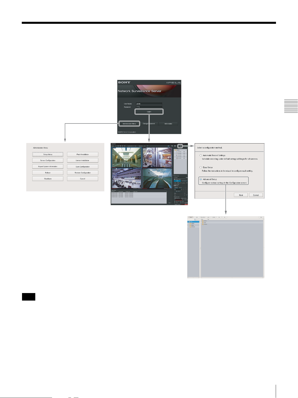
Basic Window Operations
This section provides a brief description of the basic operations for each screen.
The unit includes a Main screen for monitoring images, a configuration screen for configuring various settings, and an
Administration Menu for performing configurations and operations related to the NSR unit.
Logon Screen
Recorder Settings Screen
Chapter 3 Basic Operation
Administration Menu
Main Screen
Configuration Screen
Note
Click [Automatic Record Settings] or [Easy Setup] to register and configure cameras with a few simple operations. For
details on the operating procedures, refer to the Installation Manual (separate document).
Basic Window Operations
27
Page 28
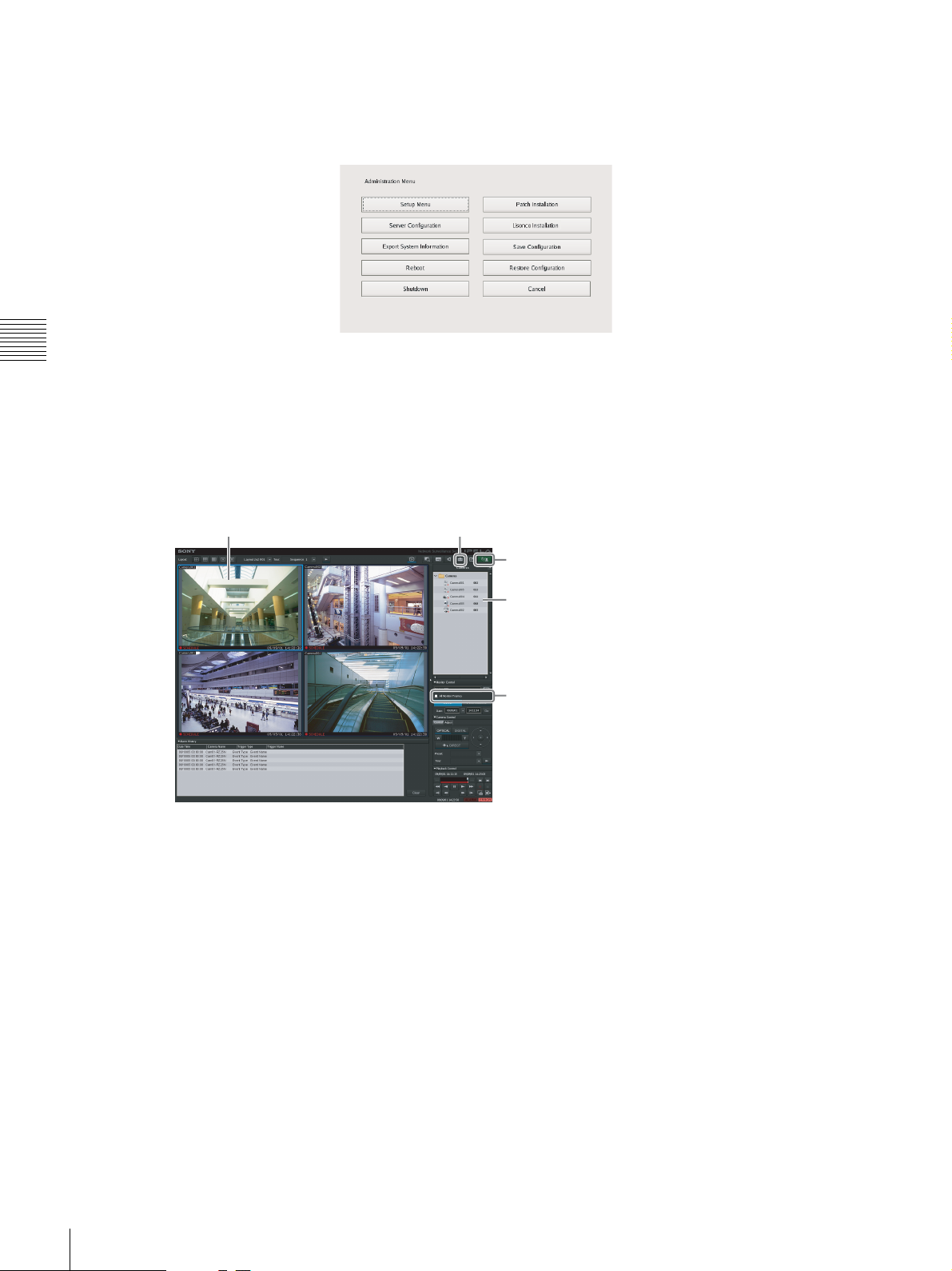
Administration Menu
When you click [Administration Menu] after entering your user name and password in the logon screen, the
Administration Menu screen appears. Click each button to configure settings and perform operations related to the NSR
unit.
Chapter 3 Basic Operation
For details on settings that can be configured from the Administration Menu, see Chapter 2 “
Administration Menu
(page 12).
Main screen
In the Main screen, you can monitor live images from each monitor frame, and search for and play back recorded images.
To switch between live image display and playback of recorded images, click the target monitor frame, and then click
[LIVE] or [PLAYBACK] on the right side of the window.
Monitor frame Displays the Configuration screen.
”
Allows you to log off or restart the NSR.
Select cameras.
Switch between live image display and
playback of recorded images.
For details on monitoring and searching for and playing back recorded images, see Chapter 5 “
(page 96).
Operation and Control
”
28
Basic Window Operations
Page 29

Configuration screen
Configure settings that are necessary for operating the NSR, such as camera registration, schedule settings, and user
registration.
Click the button for the item you want to configure.
Returns to the Main screen.
Setting items appear based on the button you clicked.
Chapter 3 Basic Operation
For details on setting items and how to configure them, see Chapter 4 “
Application Settings
” (page 33).
Basic Window Operations
29
Page 30
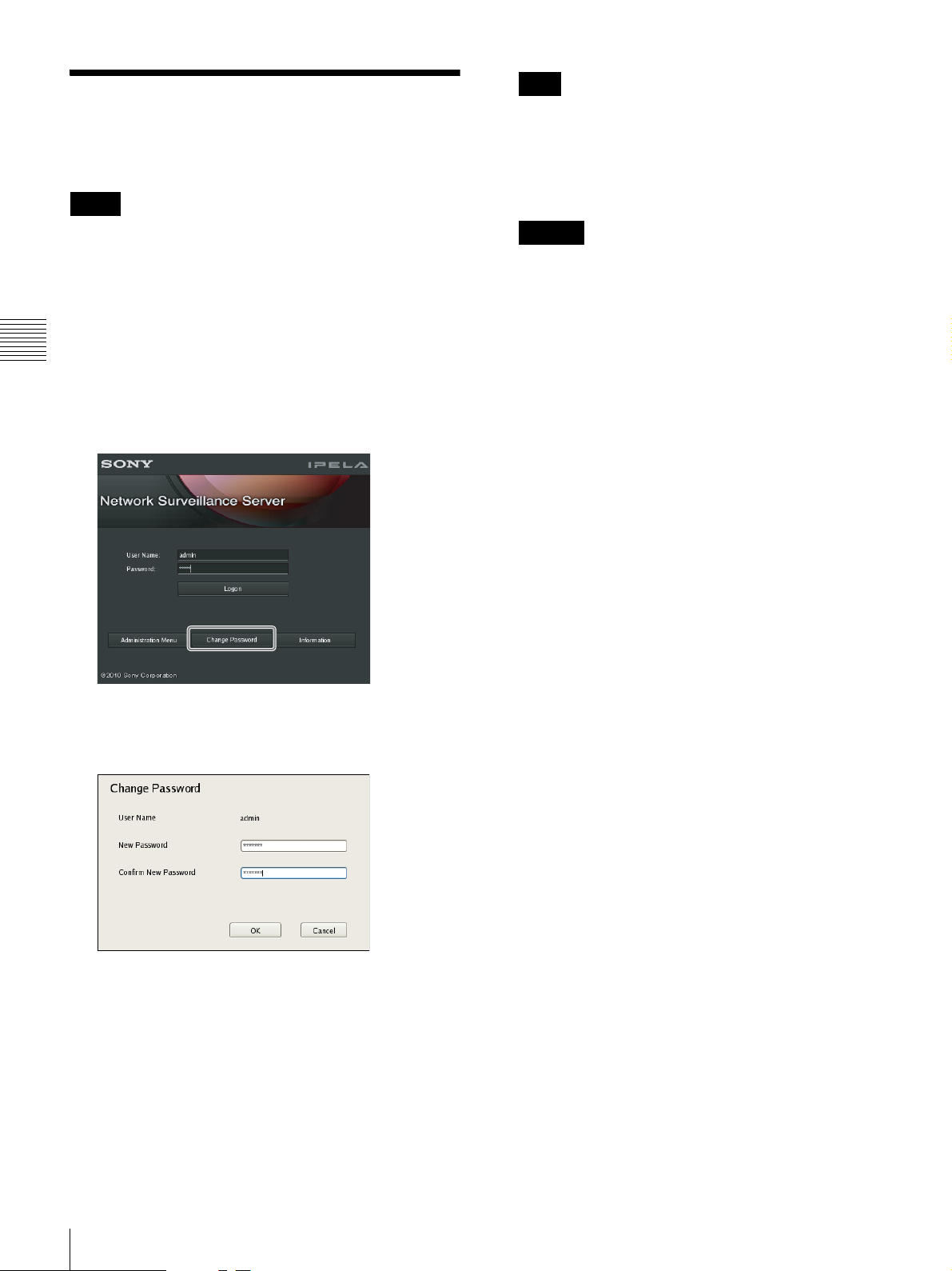
Changing the Password
You change the password for logging on to NSR.
Notes
Note
If [Enable Auto Logon] is enabled, the logon screen
will not appear during application startup, and you will
be logged on automatically. To change the password
while [Enable Auto Logon] is enabled, first log off
from the Main screen.
• The password is extremely important to the security of
this equipment. The first time you log in to NSR after
purchasing the equipment, be sure to change the
password before monitoring and configuring various
settings. Take care to keep the password secure.
• When using a System Controller (RM-NS1000) for
operations, create user names and passwords consisting
Chapter 3 Basic Operation
only of numbers.
1
Enter the user name and password on the [Logon]
screen, and click [Change Password].
Caution
When changing the password of an administrator or a
user with “User Configuration” permission, be sure to
memorize the new password.
The Change Password dialog box appears.
2
Enter a new password, and click [OK].
Enter the same password again in [Confirm New
Password].
The password is changed.
30
Changing the Password
Page 31

Logging Off
1
Click in the Main screen.
The following screen appears.
Locking the NSR
You can temporarily lock the screen in its current state.
Use the lock function when you need to leave your seat
during operation, for example.
1
Click in the Main screen.
2
Click [Logoff].
A logoff confirmation message appears.
3
Click [Logoff].
You are logged off the NSR, and the logon screen
appears.
To log on again, enter the user name and password and
click [Logon].
The following screen appears.
2
Click [Lock].
Operations are locked.
To unlock operations, enter the user name and
password and click [Unlock].
Chapter 3 Basic Operation
Note
Only the user that is currently logged on or a level 5
user can undo the lock function.
Logging Off / Locking the NSR
31
Page 32

Shutting Down and
Viewing Version
Restarting the NSR
Always shut down or restart the NSR from the Main
screen.
1
Click at the top of the Main screen, and select
[Shutdown] or [Reboot] from the menu that appears.
Chapter 3 Basic Operation
The following screen appears.
2
Click [Shutdown] or [Reboot].
Information
1
Click [Information] in the logon screen.
Version information for the software appears.
A confirmation message appears.
3
Click [Shutdown] or [Reboot].
The NSR shuts down or restarts.
Note
Under normal conditions, the NSR shuts down or
restarts after a few minutes. If the NSR does not shut
down or restart after several minutes, shut it down
manually by pressing the power switch on the front of
the unit for about five seconds.
32
Shutting Down and Restarting the NSR / Viewing Version Information
Page 33

Application Settings
Chapter
4
Alarms and Events
You can configure sensor inputs, VMD, manual actions,
and other triggers as alarms or events on the NSR, and
record or execute actions in response. Although alarms and
events are nearly identical in function, the following
functions are enabled when you configure triggers of
higher priority as alarms.
• When searching for recordings, you can search for
alarms and events separately.
• Alarm logs are listed in the alarm history of the Main
screen, and the ALARM lamp in the Main screen lights.
• A red frame appears around the monitor frame of the
camera that triggered the alarm.
• Images from the camera that triggered the alarm appear
in the hot spot.
• You can confirm alarms and events separately in the
event/alarm log.
As shown in the table below, you can configure a
recording or action for the source that will become the
trigger. In addition, the trigger will be determined as an
alarm depending on the configured recording or action.
Source to
become
trigger of
event/alarm
Sensor input a
VMD
•VMD
(camera)
System alert
Manual action – –
1) An action is performed but is not determined to be an
event or action.
Recording/Action Corresponding to
Recording setting Action setting
Event
record
(event)a(alarm)a(alarm)
a
(event)a(alarm)a(alarm)
––
Alarm
record
Event/Alarm
Camera
action I/O
a
(alarm)
1)
a
Client
action
(event)
(event)
(event)
a
a
a
1)
a
Displaying Configuration Window
You can configure various settings in the Configuration
window.
1
Click (Configuration) on the top right of the
main screen.
The Recorder setting screen appears.
2
Select [Advanced Setup], and click [Next].
Note
Selecting [Automatic Record Settings] or [Easy Setup]
allows you to register and configure cameras with a
few simple operations. For details on Automatic
Record Settings and Easy Setup, refer to the
Installation Manual (separate document).
Chapter 4
Application Settings
Alarms and Events / Displaying Configuration Window
33
Page 34

The Configuration window appears.
Chapter 4
Application Settings
3
Click the button of the item you want to set at the top
of the window.
The configuration screen that corresponds to the
button appears.
Example: When [Device] is clicked:
The Device Configuration screen appears.
Registering Devices
You can register the devices to manage with NSR, and
configure detailed settings for the operation of the devices.
There are the following way of registering devices.
• Registration Using Easy Setup
Register cameras on the network automatically. For
details on the operation, refer to the Installation Manual
(separate document).
• Selecting Automatically Detected Cameras and
Registering Them Simultaneously
Detect the devices that exist on the same network as
NSR automatically, select the cameras to register, and
then register them simultaneously. For details on the
operation, refer to the Installation Manual (separate
document).
• Registering Devices Manually
Specify the IP address of a device, and register the
device individually. For details on the operation, refer to
the Installation Manual (separate document).
Notes
• When using non-Sony IP cameras (network cameras) or
ONVIF (Open Network Video Interface Forum)
cameras, simultaneous registration through basic
configuration and automatic detection is not possible.
Register the cameras manually.
• Control protocol configuration is necessary to control
pan, tilt, and zoom on an analog camera. For details, see
“Configuring Control Protocols for Analog Cameras”
(page 50).
Changing Registration Details
This section describes the procedure for changing the
settings on the [General] tab of the Device Configuration
screen.
The items on the [General] tab allow you set multiple
cameras simultaneously.
Note
Some of the setting items differ depending on whether you
are configuring the settings of one camera or the settings
of multiple cameras simultaneously.
• A blank is displayed for setting items with which the
setting state differs for each camera. If these setting
items are saved as is, the corresponding setting items of
each camera are not modified. Reselecting an item from
a list or entering a numeral sets the new value for all of
the cameras.
34
Registering Devices
Page 35

• If a common value cannot be set for multiple cameras,
that setting item is unavailable. Change the combination
of cameras to select, and then configure the setting.
1
Select the camera(s) you want to change the
registration details of on the Device Configuration
screen.
You can also select multiple cameras at once by
holding down the Shift key or Ctrl key while selecting.
2
Click (Delete).
A confirmation message appears.
The camera registration details appear.
2
Click the [General] tab, and modify the settings of the
items you want to change.
For details on each of the items, refer to “Setting Items
of the [General] Tab” (page 38).
For details on Generic Camera, refer “Settings
Required when Using SNC-CS20/CM120/DS10/
DM110/DS60/DM160” (page 35).
3
Click [Yes].
The device is deleted.
Caution
• When a camera is deleted, “No Camera” is displayed in
the monitoring window in the layout. When you register
a camera in the default layout, the camera is assigned to
the first empty (“No Camera”) monitoring window
available.
• If you delete a camera, you will no longer be able to find
data recorded with that camera. The recorded data is not
deleted at that time. The recorded data becomes target
for deletion at the point in time when the criteria for
deleting the recordings or overwriting the data in storage
are met. For details, refer “Configuring Settings Related
to Storage” (page 63).
Chapter 4
Application Settings
3
After configuring each item, click [Apply].
The settings are changed.
Deleting Devices
1
Select the camera you want to delete on the Device
Configuration screen.
You can also select multiple devices at once by
holding down the Shift key or Ctrl key while selecting.
Settings Required when Using SNCCS20/CM120/DS10/DM110/DS60/
DM160
With the following six models1) of camera, other functions
are restricted depending on the setting values of the
functions to be used. It is necessary to prioritize and select
the functions you want to use before you configure various
settings.
• SNC-CS20 • SNC-CM120
• SNC-DS10 • SNC-DM110
• SNC-DS60 • SNC-DM160
Flow when Using SNC-CS20/CM120/DS10/
DM110/DS60/DM160
When using any of the above cameras, first select the
combination of functions to use, and then configure
various settings. First, you must select a combination of
1)
1)
Registering Devices
35
Page 36

functions and then perform the setup. When you select the
combination of functions, the setting range for each item is
determined automatically. Therefore, it is important to
select the combination of functions carefully according to
the intended use of the camera.
1 Select the combination of functions to use
↓
2 Configure the necessary settings in each setup screen
↓
3 Start operation
1) Setting restrictions may also exist on future camera models. When using a
camera for which the [Function Selection] tab appears, be sure to
configure a combination of functions as you would with the above
cameras.
Caution
• The available settings and setting value ranges will vary
depending on the function combination. Be sure to
Chapter 4
configure the settings to match the intended operation.
Example 1: When a certain codec is used, the motion
detection function will not be available. Choose a
Application Settings
• Be sure to select the function combination first and then
• After changing a setting, be sure to check all settings
1
combination with this codec only if motion
detection function settings are not required.
Example 2: When a combination with an available
setting value range of 1 to 50 has been selected, the
available range on the respective setup screens
will be limited to 1 to 50 even if the camera setting
range is 1 to 100.
configure the settings. If you select or change the
function combination after starting to configure settings,
the available ranges for values will also change
depending on the function combination, which may lead
to earlier settings being altered.
Example: 70 was selected for an item with an available
range of 1 to 100, but the available range later
became 1 to 50 because of a function combination
change, and the setting was altered to 25.
before starting operation. If the changed value is within
the available range, there will be no problem, but if it is
out of range, the setting will automatically be changed to
a value within the range.
Click [Select Camera Function] on the [Function
Selection] tab of the Device Configuration screen.
2
Select the function combination one line at a time in
order from the top left, and click the [OK] button.
Select the function you want to set with [Item], and
select the setting value with [Parameter].
Notes
• The control range is narrowed down based on your
item selection sequence and parameters. The items
and values selectable on subsequent lines will
change accordingly.
• If you change a selected line, all lower lines will
revert to the non-selected condition. Note that the
function combination selected here determines the
setting range for the various setup screens.
3
Configure the other items on the [General] tab.
Also configure the settings in each screen as
necessary.
4
After completing the setting procedure, check all the
settings to make sure they are set to appropriate values.
5
Start operation.
Registering Device Groups
You can set a device group for each floor or region that a
device is installed in order to improve management
efficiency. Also, you can set the permissions for the
operations users and user groups can perform for each
device group.
36
Registering Devices
Registering a Device Group
Select [Group] in the tree on the left of the Device
Configuration screen, and click (Add) to add a group.
A screen for selecting the function combination to use
with camera appears.
Page 37

Notes
CBD E
• When you want to create a sub-group below a group,
select the upper group and click (Add).
• When you want to rename a group, click a group name
selected in the tree and then enter the new group name.
Next, add devices to the device group.
Adding Devices to a Group
Drag and drop the devices you want to belong to the group
onto the icon of the group in the tree to add them to the
group.
Deleting a Group
Select the group you want to delete in the tree, and click
(Delete) to delete the group.
Details of Each Screen
Setting Items of Device Configuration
Screen
This screen displays a list of the devices registered to NSR.
It is displayed by clicking [Device] in the Configuration
screen.
Chapter 4
Application Settings
Removing Devices from a Group
Drag the icons of the devices you want to remove from the
group outside of the tree.
A
A Tree Structure
This displays a list of the devices registered to NSR in a
tree structure.
Selecting a device from the tree structure displays the
items corresponding to the selected device in area E.
B (Camera Auto Registration)
This displays the Camera Auto Registration dialog box for
automatically searching for and registering cameras
connected to the network.
Registering Devices
37
Page 38

C (Add)
This displays the Add Device dialog box (page 40) for
registering a device manually.
D (Delete)
This deletes a device.
Select the device you want to delete from the tree structure
or device list, and click this button to delete the device.
E Device List
This displays a list of the devices belonging to the device
group selected in the tree structure on the left.
Setting Items of the [General] Tab
This tab allows you to change the settings of the device
selected in the tree structure on the left.
After configuring each item, click [Apply] to save your
settings.
Chapter 4
Application Settings
Global ID
Enter a number for the global ID.
In NSR and RealShot Manager Advanced, cameras are
managed by assigning IDs to the connected cameras
individually.
In addition, in a system in which multiple NSR and
RealShot Manager Advanced are used as servers, all the
cameras connected to each server are assigned an ID that
is unique within the system. You can use a global ID to
specify the cameras to perform monitoring directly from
RealShot Manager Advanced of a remote client without
being aware of each server.
IP Address
Enter the IP address or the host name for the camera.
Caution
When specifying host names, be sure to configure DNS
settings so that the host names can be resolved.
Port
Enter the port number on the camera side for when
connecting with the camera. The default setting is “80.”
Proxy
Set this when the camera will be accessed via a proxy
server.
Name
Enter up to 32 characters (excluding \ / : , ; * ? " < > ¦ [ ])
to assign a name to the device to be added.
Model
This item displays the device type. It cannot be changed.
User Name
Enter the user name for connecting to the device. It can be
up to 32 characters and consist of alphanumeric characters.
Password
Enter the password for connecting to the device. It can be
up to 32 characters and ASCII characters (upper or lower
case alphanumeric characters and symbols (! " # $ % & ' (
) * + , - . / : ; < = > ? @ [ \ ] ^ _ ` { | } ~)).
Caution
The user name and password for a device cannot be
changed from NSR. To change them, access the device
directly from a Web browser. For details, refer to the
instruction manual of the device to be used. If you change
the user name and password for a device registered to
NSR, you must also change the configurations in NSR.
Enable
Select the check box, and configure the following
items.
IP Address
Enter the IP address for the proxy server.
Port
Enter the port number for the proxy server.
Preview
This displays the images from the camera.
Apply
This saves the settings.
Cancel
This cancels the settings.
Close
This closes the screen.
38
Registering Devices
Page 39

Setting Items of Multiple Camera
Registration Dialog Box
This dialog box displays the results of the automatic
search, and allows you to register the detected devices
simultaneously.
It is displayed by selecting [Open Multiple Camera
Registration Window] in the Camera Auto Registration
dialog box, and clicking [OK].
After configuring each item, click [Register].
Device List
This displays a list of the devices detected with the
automatic search.
Terget
Select the check boxes of the devices to register to
NSR.
Thumbnail
This displays thumbnail images from the camera.
Images may not be displayed in some cases.
Model Name
This displays the type of device.
Camera Name
This displays the device name.
IP Address
This displays the IP address of the device.
Caution
Analog cameras without input signals will not be detected
with the automatic search.
Network
A list of the devices connected to the network selected in
the drop-down menu is displayed.
Reload
This performs the automatic search again.
Take care because apart from the user name and password
of the administrator, all of the values you entered up until
now will be replaced with the results obtained with the
automatic search.
Input All
This displays the Input All dialog box (page 40).
Show
This allows you to use the following conditions to narrow
down the display of devices shown in the device list.
Unregistered Cameras
This displays only the devices that have not yet been
registered to NSR.
Registered Cameras
This displays only the devices that have already been
registered to NSR.
All Cameras
This displays all of the devices detected with the
automatic search.
Port
This displays the port number on the device side for
when connecting with the device.
The default setting is “80.”
User Name
Enter the user name for connecting to the device.
Password
Enter the password for connecting to the device.
Serial No.
This displays the serial number of the device.
Version
This displays the firmware version of the camera.
Mac address
This displays the MAC address of the device.
Network
This displays the network in which the device is
corrected.
Caution
The user name and password for a device cannot be
changed from NSR. To change them, access the device
directly from a Web browser. For details, refer to the
instruction manual of the device to be used. If you
change the user name and password for a device
registered to NSR, you must also change the
configurations in NSR.
Registration
This registers the devices with check marks to NSR, and
closes the dialog box.
Cancel
This cancels the registration and close the dialog box.
Chapter 4
Application Settings
Registering Devices
39
Page 40

Setting Items of Input All Dialog Box
This dialog box allows you to simultaneously configure
the same setting values to multiple selected devices for the
following setting items when registering devices detected
via automatic search.
It is displayed by clicking [Input All] in the Multiple
Camera Registration dialog box (page 39).
Select the check boxes of the items you want to set, enter
the setting values, and click [OK].
Chapter 4
User Name
Enter the user name for connecting to the device. It can be
up to 32 characters and consist of alphanumeric characters.
Application Settings
Setting Items of Add Device Dialog Box
Enter the setting items when registering a device manually.
This dialog box is displayed by clicking (Add) on the
Device Configuration screen (page 37).
After configuring each item, click [OK].
Caution
Only the name can be configured for analog cameras.
Password
Enter the password for connecting to the device. It can be
up to 32 characters and ASCII characters (upper or lower
case alphanumeric characters and symbols (! " # $ % & ' (
) * + , - . / : ; < = > ? @ [ \ ] ^ _ ` { | } ~)).
IP Address
Enter the IP address for the device.
When registering multiple devices simultaneously, IP
addresses are configured sequentially, starting with the
entered address.
Port No.
Enter the port number on the device side for when
connecting with the device.
The default setting is “80.”
OK
This reflects the setting values in the device list of the
Multiple Camera Registration dialog box, and closes the
dialog box.
Cancel
This cancels your settings, and closes the dialog box.
Device Type
Select the model name for the camera.
Normally, select “Auto Connect.”
When setting this manually, select the model name.
Name
Enter up to 32 characters (excluding \ / : , ; * ? " < > ¦ [ ])
to assign a name to the camera to be added.
IP Address
Enter the IP address or the host name for the camera.
Port
Enter the port number on the camera side for when
connecting with the camera. The default setting is “80.”
Proxy
Set this when the camera will be accessed via a proxy
server.
Enable
Select the check box, and configure the following
items.
IP Address
Enter the IP address or the host name for the proxy
server.
40
Registering Devices
Port
Enter the port number for the proxy server.
Page 41

User Name
Enter the user name for connecting to the device. It can be
up to 32 characters and consist of alphanumeric characters.
Password
Enter the password for connecting to the device. It can be
up to 32 characters and ASCII characters (upper or lower
case alphanumeric characters and symbols (! " # $ % & ' (
) * + , - . / : ; < = > ? @ [ \ ] ^ _ ` { | } ~)).
OK
This registers the device with the set values, and closes the
dialog box.
Configuring Camera Video Settings
You can configure settings related to the images captured
from a camera.
The setting items and selectable values differ depending on
the camera. In addition, some functions may be limited
depending on configurations. For details, refer to the
manual for your camera.
Close
This cancels the registration, and closes the dialog box.
1
Click [Device] at the top of the Configuration window,
and select the camera for which you want to configure
the settings for captured images.
The registration details of the selected camera appear.
2
Click the [Video] tab, and configure each item.
For details on each of the items, refer to “Setting Items
of [Video] Tab” (page 42).
3
Click [Apply].
Chapter 4
Application Settings
The settings are changed.
Configuring Camera Video Settings
41
Page 42

Setting Items of [Video] Tab
This tab allows you to change settings related to images
captured from the camera selected in the tree on the left.
After configuring each item, click [Apply] to save your
settings.
Chapter 4
Notes
• The setting items and selectable values differ depending
on the camera.
Application Settings
• For details on settings for the SNC-XX600 series (XX
represents two letters), see “Setting Items of [Video] Tab
(for the SNC-XX600 series)” (page 43).
Video Channel
In the case of a camera server with multiple channels (SNT
series, etc.), the video channel to use is displayed.
E-Flip
Configure to enable the E-Flip function for flipping the top
and bottom of images output from the camera.
E-Flip (Recorder) is the image flip function on NSR.
E-Flip (Camera) is the image flip function on the camera.
Audio Channel
Select the analog camera audio channel to tie to the analog
camera.
Bit Rate (for MPEG4 or H.264)
Select the bit rate for images of the camera.
Frame Rate
Select the frame rate for images of the camera.
Event/Alarm Record
Configure settings related to images for when recording an
alarm or event.
Codec
Set the image codec for the camera. Select JPEG,
MPEG4 or H.264.
Image Size
Select the resolution for the camera.
Image Quality (for JPEG)
Select the image quality for images of the camera.
Bit Rate (for MPEG4 or H.264)
Select the bit rate for images of the camera.
Frame Rate
Select the frame rate for images of the camera.
Monitoring
Configure settings related to images for when monitoring.
Codec
Set the image codec for the camera. Select JPEG,
MPEG4 or H.264.
Image Size
Select the resolution for the camera.
Image Quality (for JPEG)
Select the image quality for images of the camera.
Bit Rate (for MPEG4 or H.264)
Select the bit rate for images of the camera.
Frame Rate
Select the frame rate for images of the camera.
Note
You can only select from CH01 to CH04 for the audio
channel. The audio of each channel can be used.
Schedule Record
Configure settings related to images for when scheduling
recording.
Codec
Set the image codec for the camera. Select JPEG,
MPEG4 or H.264.
Image Size
Select the resolution for the camera.
Image Quality (for JPEG)
Select the image quality for images of the camera.
42
Configuring Camera Video Settings
Light Funnel
Select the mode to use when the camera has a light funnel
function.
Note
The light funnel function may not be able to be used
depending on the conditions. For details, check the user’s
guide for the camera.
Threshold
Select the brightness for when to switch to night mode.
Hold Time
Select the time for responding to changes in
brightness.
Page 43

View-DR
Select whether the View-DR function is turned on or off
for cameras equipped with this function.
Turning on the View-DR function allows the camera to
improve the visibility of images, reducing overexposure
and underexposure even in high-contrast environments,
such as under backlighting, by combining the normal
image with an image taken at high shutter speed.
Visibility Enhancer
If the camera is equipped with the Visibility Enhancer
function, select [High], [Middle], [Low], or [Off] as the
amount for the camera to automatically adjust the image
brightness and contrast.
When you turn on the Visibility Enhancer function, the
camera optimizes the contrast pixel-by-pixel,
compensating for the overexposure of bright areas and for
the underexposure of dark areas. This allows the camera to
record a vivid image even in high-contrast environments,
such as under backlighting.
If you do not want to use the Visibility Enhancer function,
select [Off].
XDNR
If the camera is equipped with the XDNR function, select
[High], [Middle], [Low], or [Off] as the strength of the
noise reduction filter applied by the camera to reduce the
amount of image noise.
When you turn on the XDNR function, the camera
distinguishes between noise occurring in areas of the
image without motion and those with motion, and
performs the appropriate noise reduction on each for better
image visibility.
This improves the effectiveness of the camera under
lowlight conditions.
If you do not want to use the XDNR function, select [Off].
IR Illuminator
If the camera is equipped with the IR illuminator function,
configure the operations of the infrared sensor.
Mode
Select [Sync with Day/Night] or [Off].
When [Sync with Day/Night] is selected, the infrared
sensor operates in coordination with the switch
between day and night.
If you do not want to use the infrared sensor, select
[Off].
Edge Storage
Select this check box if the camera is equipped with an
Edge Storage function and you want to download the
images stored on the camera’s Edge Storage.
When this function is enabled and a video loss occurs
during a recording schedule or the unit restarts, video is
recorded to the camera’s Edge Storage, allowing you to
retrieve the data later after the system is restored.
In addition, the following settings on the camera will be
configured automatically when this function is enabled.
Setting Configuration
Edge Storage On
Overwrite setting Off
Video recording Video 1 or Video 2
Audio recording Off
Recording
duration
Recording mode Alarm recording, Condition: 1, 1: Network
Active time frame Always
Caution
If Video 1: 1 second before alarm/event
start, 10 seconds after alarm/event start
If Video 2: 0 seconds before alarm/event
start, 10 seconds after alarm/event start
disconnection, Monitoring IP: IP address
of this unit
• A recording schedule must be configured to use this
function.
• For details on the recommended values for the video
settings, refer to the release notes for the camera.
Setting Items of [Video] Tab (for the
SNC-XX600 series)
Configure each setting for [Video 1] to [Video 3], and
specify the video codec to use for monitoring and manual
recording.
After configuring each item, click [Apply] to save your
settings.
Chapter 4
Application Settings
Maximum Strength
Select the maximum strength of the infrared beam.
Six levels are available for the maximum strength,
with 1 as the weakest and 6 as the strongest.
Configuring Camera Video Settings
43
Page 44

Notes
• The setting items and selectable values differ depending
on the camera. In addition, some functions may be
limited depending on configurations. For details, refer to
the manual for your camera.
• For details on supported cameras, refer to the release
notes.
Wide dynamic range (View-DR)
Select whether the View-DR function is turned on or off
for cameras equipped with this function.
Turning on the View-DR function allows the camera to
improve the visibility of images, reducing overexposure
and underexposure even in high-contrast environments,
such as under backlighting, by combining the normal
image with an image taken at high shutter speed.
Video Channel
In the case of a camera server with multiple channels (SNT
series, etc.), the video channel to use is displayed.
E-Flip
Configure to enable the E-Flip function for flipping the top
and bottom of images output from the camera.
E-Flip (Recorder) is the image flip function on NSR.
E-Flip (Camera) is the image flip function on the camera.
Audio Channel
Select the analog camera audio channel to tie to the analog
Chapter 4
camera.
Note
Application Settings
You can only select from CH01 to CH04 for the audio
channel. The audio of each channel can be used.
Video 1 to Video 3
Configure video settings for [Video 1] to [Video 3].
Note
[Video 2] and [Video 3] cannot be configured for some
cameras. For details, refer to the manual for your camera.
Codec
Set the image codec for the camera. Select JPEG or
H.264.
Profile
Select Baseline, Main, or High for the profile when the
selected codec is H.264.
Visibility Enhancer
If the camera is equipped with the Visibility Enhancer
function, select [High], [Middle], [Low], or [Off] as the
amount for the camera to automatically adjust the image
brightness and contrast.
When you turn on the Visibility Enhancer function, the
camera optimizes the contrast pixel-by-pixel,
compensating for the overexposure of bright areas and for
the underexposure of dark areas. This allows the camera to
record a vivid image even in high-contrast environments,
such as under backlighting.
If you do not want to use the Visibility Enhancer function,
select [Off].
XDNR
If the camera is equipped with the XDNR function, select
[High], [Middle], [Low], or [Off] as the strength of the
noise reduction filter applied by the camera to reduce the
amount of image noise.
When you turn on the XDNR function, the camera
distinguishes between noise occurring in areas of the
image without motion and those with motion, and
performs the appropriate noise reduction on each for better
image visibility.
This improves the effectiveness of the camera under
lowlight conditions.
If you do not want to use the XDNR function, select [Off].
Monitoring
Select the video codec to use during monitoring.
Manual Recording
Select the video codec to use during manual recording.
Image Size
Select the resolution for the camera.
CBR/VBR
Select CBR (constant bit rate) or VBR (variable bit
rate) for the bit rate.
Bit Rate
Select the bit rate for images of the camera.
Frame Rate
Select the frame rate for images of the camera.
44
Configuring Camera Video Settings
Note
The video codec used during schedule recording is
selected in the Schedule Configuration screen.
Page 45

Configuring Camera
1
Operations
In NSR, you can configure the following settings for
camera operations.
• “Configuring Preset Positions” (page 45)
You can configure preset positions for the camera.
• “Configuring Camera Tours” (page 46)
You can configure camera tours for sequentially moving
a camera to the pan, tilt, and zoom positions specified for
presets.
• “Configuring Control Protocols for Analog Cameras”
(page 50)
You can configure settings for controlling the pan, tilt,
and zoom on an analog camera.
Configuring Preset Positions
This section describes configuring camera preset
positions.
These settings are only available for cameras with a
function for configuring preset positions. The items and
buttons on the [Preset] tab are unavailable for cameras
without a function for configuring preset positions.
Configuring a New Preset Position
3
Configure each item.
1 Select the field of the position (position number) to
create the preset, and enter the preset name.
2 Confirm the images in the preview area while
operating the pan, tilt, and zoom to adjust the
camera position.
You can also select a preset, and move the camera
to the preset position.
3 Click [Set preset].
The current camera position is stored as a preset.
When creating multiple presets, repeat Steps 1 to
3.
3
2
Chapter 4
Application Settings
1
Click [Device] at the top of the Configuration window.
The Device Configuration screen appears.
2
Select the camera for which you want to configure the
preset position, and click the [Preset] tab.
Images from the camera are displayed in the preview
area.
Note
The number of presets depends on the type of camera
used. For details, refer to the manual for your camera.
4
When you have finished configuring the settings, click
[Apply].
Changing Preset Settings
1
Select the camera for which you want to change the
preset position, and click the [Preset] tab.
2
When changing the preset name, re-enter the preset
name in the list at the top of the screen.
3
When changing the preset position, operate the pan,
tilt, and zoom to adjust the camera position.
4
Click [Set preset].
The settings are changed.
Configuring Camera Operations
45
Page 46

Deleting Presets
1245
1
Select the camera for which you want to delete the
preset position, and click the [Preset] tab.
2
Select the preset to delete in the list at the top of the
screen, and click [Clear].
The preset is deleted.
3
Click [Set Preset].
Configuring Camera Tours
You can configure camera tours for sequentially moving a
camera to the pan, tilt, and zoom positions specified for
presets.
Note
Chapter 4
The tour function uses the built-in tour features on a
camera. As a result, tour configuration information is
stored on the camera.
Application Settings
3
Configure each item.
1 Select [Preset Tour].
2 Select the number of the tour you want to configure.
3 Click (Add), select the preset to add in the
Select Preset dialog box that appears, and click
[OK].
3
7
8
6
Setting a New Tour
1
Click [Device] at the top of the Configuration window.
The Device Configuration screen appears.
2
Select the camera for which you want to configure the
tour, and click the [Tour] tab.
Images from the camera are displayed in the preview
area.
The preset is added to the list.
4 Enter the amount of time that the camera will
remain at that position in [Stay Duration], and enter
the speed (level) for moving the camera in [Speed].
For details on camera speeds (levels), refer to the
user’s guide for your camera.
5 In [Resume time on inactivity], configure the
duration after which a tour resumes when it is
interrupted by an operation.
46
Configuring Camera Operations
6 When you want to change the preset order, select a
preset in the list and click (Move preset of tour
up one place) or (Move preset of tour down one
place).
7 When you have finished configuring the presets,
click [Set Tour].
Page 47

8 Click [Test] to show and check the set tour.
2 413
To Configure a New Tour
Camera Tour Operation
In NSR, the camera tour function is achieved by
configuring the same stay duration and speed for each
position specified by a camera preset.
Notes
• The configured stay duration is applied to all preset
positions, and the configured speed is applied to all
preset movements.
• The camera tour appears with a name (P-1, P-2, …) in
the [Tour] list on the [Camera Control] pane of the Main
screen.
Caution
Even if the values configured for the camera speed (level)
are the same, actual speeds may differ depending on the
models of camera. When configuring the settings of a tour,
be sure to test the tour to confirm the operation.
Changing Settings
1
Select the camera(s) you want to change the
registration details of on the Device Configuration
screen.
1
Click [Device] at the top of the Configuration screen.
The Device Configuration screen appears.
2
Select the camera for which you want to configure a
tour, and then click [Tour].
The camera image appears in the preview area.
3
Configure each of the setting items.
7
6
Chapter 4
Application Settings
2
Click the [Tour] tab, and modify the settings of the
items you want to change.
3
Click [Set Tour].
The settings are changed.
Configuring Shadow Tours
For cameras equipped with the shadow tour function, you
can record the motions of the camera, when operated
remotely using a mouse or joystick, and configure them as
a shadow tour.
You can configure up to four tour operations (S-1 to S-4).
Note
These tours use the tour function of the camera. As a result,
the configured tour information is saved on the camera.
5
1 Select [Shadow Tour].
2 Select the tour number you want to configure.
3 For [Resume time on inactivity], set the length of
time to wait before resuming the tour after it is
interrupted by an operation.
4 Click [Record] to start recording.
5 Adjust the camera position using the pan, tilt, and
zoom operations while confirming the image in the
preview area.
You can also select [Preset] to make the camera
move to a preset position.
6 Click [Stop] to finish recording.
7 Click [Test] to display and confirm the configured
tour.
Configuring Camera Operations
47
Page 48

Notes
• Recording time may be limited depending on the camera
specifications.
• If the recording time available on the camera is
exceeded, recording will stop before you click [Stop].
• The shadow tour appears with a name (S-1to S-4) in the
[Tour] list on the [Camera Control] pane of the Main
screen.
3
Configure each item.
For details on each of the items, refer to “Setting Items
of [Mask (Camera)] Tab” (page 49).
1
Configuring Masks (Camera)
You can use the camera’s built-in mask function to
configure masks for hiding specific areas within images
monitored by the camera. The mask function works in
conjunction with the camera’s pan, tilt, and zoom
movements to constantly hide the specified areas.
The mask function (camera) can only be used with Sony
SNC-XX600 series (XX represents two letters) network
Chapter 4
cameras that support camera masks.
Notes
Application Settings
• A mask area configured for a camera with pan and tilt
functions may shift when the camera is panned, tilted, or
zoomed. When configuring the mask area, allow for
approximately 10% (of the full image size) of additional
space around the object you wish to mask. In addition, be
sure to position the object you wish to mask in the center
of the monitoring screen before configuring a mask area
for a camera with pan and tilt functions.
• When configuring the mask settings from a client, be
sure to preview the settings before configuring them.
1
Click [Device] at the top of the Configuration window.
2
3
4
5
1 Enter the name of the mask.
2 Select how the mask will be displayed.
3 Use these buttons to create the mask while checking
the image in the preview area.
4 For a camera equipped with pan, tilt, and zoom
functions, use these buttons to control the pan, tilt,
and zoom of the camera, and to confirm whether the
camera moves properly so as to hide the area you
set.
You can also select a preset, and move the camera
to the preset position.
5 Click [Apply].
The mask you created is added to the list.
When creating multiple masks, repeat Steps 2 to
5.
The Device Configuration screen appears.
2
Select the camera for which you want to configure the
mask, and click the [Mask] tab.
Images from the camera are displayed in the preview
area.
48
Configuring Camera Operations
Notes
• Setting changes will be applied immediately after
you click [Apply].
• The number of masks that can be configured varies
depending on the camera specifications.
Page 49

Setting Items of [Mask (Camera)] Tab
A
A
After configuring each item, click [Apply].
E
F G H
Setting Items of [Video] Tab (for the
SNC-XX600 series)
B
C
D
D Pan, Tilt, and Zoom Toolbar
This is available when the camera is equipped with pan,
tilt, and zoom functions.
Use the buttons to control the pan, tilt, and zoom of the
camera, and check whether or not the camera moves
correctly to hide a configured area.
You can also select a preset, and move the camera to the
preset position.
Caution
• A mask area configured for a camera with pan, tilt, and
zoom functions may shift when the camera is panned,
tilted, or zoomed. When configuring the mask area,
leave approximately 10% of additional space around the
object you wish to mask.
• Images in the left and right or top and bottom areas of the
preview image may not appear in some cases. In such
cases, you can display the entire image by changing the
resolution used for monitoring.
E Preview Area and Tool Buttons
Use these buttons to configure the mask while checking
the image in the preview area.
Chapter 4
Application Settings
B
C
D
E
F G H
A Mask List
This displays a list of the masks configured for the device
selected in the tree structure.
B Mask Type
Select how the mask will be displayed.
The mask types that can be selected vary depending on the
camera.
C Data
If [Single color] is selected as the mask type, a list of color
names appears.
(Create/Move Area)
Use this button to create a rectangular mask or move a
mask by dragging with the mouse.
(Edit Points)
Use this button to edit points and create masks of
complex quadrilateral shapes.
(Remove Area)
Use this button to delete the selected mask.
(Refresh Image)
Use this button to refresh the still image that includes
all the masks.
You can continue editing afterwards.
(Preview)
Use this button to display live images from the camera
that includes the mask.
This allows you to confirm how the configured area
will appear.
F Apply
This saves the settings.
G Cancel
This cancels the changes to the settings.
H Close
This closes the screen.
Configuring Camera Operations
49
Page 50

Configuring Control Protocols for
1
24
Analog Cameras
When an optional NSBK-EB05 is installed, configure the
control protocols for the analog cameras to control the pan,
tilt, and zoom on the cameras.
1
Click [Device] at the top of the Configuration window.
The Device Configuration screen appears.
2
Select the camera server or NSBK-EB05, and click the
[Control] tab.
Chapter 4
Application Settings
Note
Make sure that the serial port is configured according to
the analog camera you are using. You can configure the
serial port from the Setup Menu of the Administration
Menu.
Configuring Network Camera Control
You can configure settings to control pan and tilt speed
based on the zoom level of the camera.
1
Click [Device] at the top of the Configuration window.
The Device Configuration screen appears.
2
Select the network camera, and click the [Control] tab.
3
Configure each item.
3
1 Select a protocol in accordance with the analog
camera.
2 Click [Apply].
3 Select [Control] for each channel, and configure the
control number configured on the analog camera.
3
Select the [Auto Pan & Tilt Speed] check box, and
click [Apply].
Pan and tilt speed will be controlled based on the zoom
level of the camera.
4 Click [Apply].
Controlling the pan, tilt, and zoom on the analog
camera becomes possible.
50
Configuring Camera Operations
Page 51

Configuring Audio
Configure settings for monitoring audio.
1
Click [Device] at the top of the Configuration window.
The Device Configuration screen appears.
2
Select the camera for which to enable audio, and click
the [Audio] tab.
3
Configure each item, and click [Apply].
Settings Related to Monitoring
You can configure the following settings related to the
monitor layout and camera images.
• “Configuring Monitor Layout Settings” (page 51)
You can create multiple layouts according to your
operating environment and objective.
• “Assigning Cameras to Monitor Frames” (page 57)
You can assign a camera to each monitor frame.
• “Configuring Layout Tours” (page 57)
You can sequentially switch the display of each display
at a preset time.
Configuring Monitor Layout Settings
By setting the number and size of camera monitor frames,
you can create a layout according to your operating
environment and objective.
Notes
Chapter 4
Application Settings
Enable
Select this check box to allow the NSR to receive
audio from the camera.
To monitor audio, the microphone input on the camera
must also be enabled.
Caution
If you clear the check box to disable audio and then
play back a recording that was created while audio was
enabled, the audio will not play back. To play back the
audio in such cases, select the check box and re-enable
audio first.
• When you register a camera, the layouts 2×2, 3×3, and
4×4 are created as the default layouts automatically. The
size of the monitor frame cannot be changed for the
default layout.
• Created layouts are saved on the NSR they are created
on. For example, layouts created on a remote client
(RealShot Manager Advanced Client Software) are
saved on the remote client.
Creating a New Layout
1
Click [Layout] at the top of the Configuration window.
The Layout Configuration screen appears.
2
Select “Custom Layout A” or “Custom Layout B”
from the [Layout] tree, and click (Add).
Codec
Specify the audio codec.
Record
Select this check box to record audio from the camera.
Settings Related to Monitoring
51
Page 52

Chapter 4
1 53 2
Application Settings
Note
“Custom Layout A” and “Custom Layout B” are
preset layout groups. Use them according to your
objective.
The area on the left side changes to the display for
setting the layout.
3
Configure each item.
For details on each of the items, refer to “Setting Items
of Layout Configuration Screen” (page 53).
4
6
For details on each of the items, refer to “Setting
Items of Insert Background Image Dialog Box”
(page 56).
4 Move the monitor frames to determine their
positions, as necessary.
Move the monitor frames by dragging them with
the mouse.
5 Set a hotspot monitor, as necessary.
Click to select one monitor frame to specify as the
hotspot monitor, and click [Hotspot].
A hotspot monitor displays the same images as the
camera monitor frame currently selected on the
main screen. To make images from the camera
monitor frame easier to see, the hotspot monitor is
specified to be larger than a regular camera monitor
frame.
1 Enter a name for the layout, as necessary.
You can enter up to 32 characters.
2 Set the number and layout of monitor frames.
Click [Template], set each item in the Insert
Template dialog box that appears, and click [OK].
For details on each of the items, refer to “Setting
Items of Insert Template Dialog Box” (page 56)
3 Import an image such as a map or floor plan for the
background, as necessary.
Click [Background], set each item in the Insert
Background Image dialog box that appears, and
click [OK].
6 Configure each tab of [Properties], as necessary.
For details on the setting items of each tab, refer to
“Setting Items of Properties” (page 54).
4
After configuring each item, click [Apply].
The layout is created.
Changing Registration Details
1
Select the layout you want to change the registration
details of on the Layout Configuration screen.
2
Reconfigure each item.
3
Click [Apply].
The settings are changed.
Deleting Layouts
Note
Default layouts cannot be deleted.
52
Settings Related to Monitoring
Page 53

1
B C DE F
LM N
Select the layout you want to delete from the [Layout]
tree on the Layout Configuration screen, and click
(Delete).
Note
Default layouts cannot be deleted.
A confirmation message appears.
2
Click [Yes].
The layout is deleted.
Setting Items of Layout Configuration
Screen
This screen is displayed by clicking [Layout] in the
Configuration window.
After changing the settings, click [Apply] to save your
settings.
G
A
K
H
I
J
B Name
Enter the name of the layout. It can be up to 32 characters
long.
C Show on the Main Window
Select the check box to enable this layout to be displayed
on the main screen.
D Hotspot
Set the hotspot monitor.
Click to select one monitor frame to specify as the hotspot
monitor, and click this button.
If you set a hotspot monitor, when you click a certain
monitor frame or an alarm is generated, images are
displayed on the monitor frame set as the hotspot monitor.
A hotspot monitor displays the same images as the camera
monitor frame currently selected on the main screen. To
make images from the camera monitor frame easier to see,
the hotspot monitor is specified to be larger than a regular
camera monitor frame.
E Background
This displays the Insert Background Image dialog box
(page 56) for importing an image such as a map or floor
plan for the background.
F Template
This displays the Insert Template dialog box (page 56) for
setting the number and layout of monitor frames.
Chapter 4
Application Settings
A [Layout] Tree
This displays a list of the configured layouts in a tree
structure.
Selecting a layout from the tree displays the setting details
in the area on the right.
(Add)
This creates a new layout.
Select “Custom Layout A” or “Custom Layout B,” and
click this button.
Note
“Custom Layout A” and “Custom Layout B” are
preset layout groups. Use them according to your
objective.
(Delete)
This deletes a layout.
Select the layout you want to delete from the tree, and
click this button to delete the layout.
G Tool Buttons
(Insert Image)
Use this button to display the Insert Image dialog box
(page 56) for inserting an image.
(Insert Image Map)
Use this button to insert an image map.
You can assign an action to a specific area in the image
background using an image map. When you click
within this area, the assigned action is activated.
(Remove Item)
Use this button to remove the selected item.
(Remove Assigned Cameras)
Use this button to remove the cameras assigned to the
selected monitor frame.
(Bring to Front)
Use this button to move the selected image in front of
all others.
(Bring Forward)
Use this button to move the selected image forward.
Settings Related to Monitoring
53
Page 54

(Send Backward)
Use this button to move the selected image backward.
(Send to Back)
Use this button to move the selected image behind all
others.
(Flip Horizontally)
Use this button to flip the selected image horizontally.
(Rotate)
Use this button to spin the selected image 90 degrees
counterclockwise.
Setting Items of Properties
x When a monitor frame is selected:
•[General] Tab
Select the camera to assign to the monitor frame.
(Grid)
Use this button to display grid lines to assist in placing
monitor frames and images.
H Monitor Frame
A monitor frame is created by dragging to any size in the
configuration area of the layout and using a template.
Chapter 4
This is used to monitor live images and play back
recordings.
For each monitor frame, you can specify the camera that
displays images.
Application Settings
By configuring a large monitor frame as a hotspot monitor,
you can display a larger version of the same image that
appears in the currently selected monitor frame.
I Actual Size/Window Size
When you are editing a layout and want to see the whole
layout, select [Window Size].
When you want to confirm a layout at actual scale, select
[Actual Size].
J Properties Tabs
This displays tabs for configuring the advanced settings of
the monitor frames, images, and image map. For details on
the setting items of each tab, refer to “Setting Items of
Properties” (page 54).
Camera
Select the camera to assign to the monitor frame.
• [Display Information] Tab
Select the check boxes for the items to display on the
monitor frame.
Camera Name
This displays the name of the camera set on the Device
Configuration window.
Status
This displays error messages, such as “NO
CONNECTION.”
Time
This displays the current time.
Display Image per Second
This displays the speed at which camera images on the
display are refreshed.
K [Device] Tree
This displays a list of the devices registered to NSR in a
tree structure.
When you are creating a layout, you can assign cameras by
dragging and dropping them from the [Device] tree to
monitor frames.
L Apply
This saves the settings.
M Cancel
This cancels the changes to the settings.
N Close
This closes the screen.
54
Settings Related to Monitoring
Frame Rate
This displays the import speed for camera images.
Bandwidth
This displays the amount of bandwidth to use for
transferring images over a network connection.
Apply to All Monitor Frames
This applies the items with check marks to all monitor
frames.
•[Options] Tab
Select how the image size should appear when the size
of the monitor frame changes.
Page 55

Scale to Monitor Frame
Images are enlarged or reduced to fit the monitor
frame.
Keep Aspect Ratio
This maintains the image aspect ratio, regardless of
the size of the monitor frame.
Restrict the display image per second
This reduces the processing load on the system by
limiting the display to only I-frames.
This function is only available for cameras on which
MPEG4/H.264 has been selected for the codec.
Click Action
Select the check box to enable an action, and select the
action to perform.
• [Camera Select] Tab
Set the function for displaying an image of the
specified camera in the specified monitor frame when
you select the image or image map.
Apply to All Monitor Frames
This applies the items with check marks to all monitor
frames.
xWhen an image or image map is selected:
•[General] Tab
Configure settings related to the inserted image or
image map.
File Name
Click [Reference], and specify the image file to insert.
Reload Original Size
This displays the image at the original size.
Transparent Color
This option allows you to set one color in the image as
a transparent color.
Select the check box, click within the box, and specify
the color to make transparent in the dialog box that
appears.
Camera Select
Select the check box to enable this function, and
configure the following items.
Server
Select the remote server.
This item is displayed in the case of a client.
Camera
Select the camera to assign to the monitor frame.
Monitor Frame
Select the monitor frame to display the images of
the camera.
• [Highlight] Tab
Configure settings for the highlight function that
displays flashing red frames around images in the
layout during specified conditions.
Chapter 4
Application Settings
• [Action] Tab
Assign actions to the selected image or image map. If
an action is assigned to the selected image or image
map, clicking the mouse within the image performs the
set action.
Enable
Select this check box to enable the highlight function.
Alarm Trigger Only
Select this check box to highlight icons only when an
alarm occurs.
Highlight Off Timing
Select the timing at which highlight display ends.
Settings Related to Monitoring
55
Page 56

Alarm/Event Trigger Off
Highlight display ends when the alarm or event
trigger ends.
Icon Click
Highlight display ends when you click the image.
Select Trigger
Displays the [Select Trigger] dialog box (page 57)
used for selecting triggers with which to initiate
highlight display.
Summary of Trigger
Displays a list of triggers selected in the [Select
Trigger] dialog box (page 57).
Setting Items of Insert Template Dialog
Box
This dialog box creates a new layout.
It is displayed by clicking [Template] on the Layout
Chapter 4
Configuration screen (page 53).
After configuring each item, click [OK].
Setting Items of Insert Background Image
Dialog Box
This dialog box imports an image such as a map or floor
plan for the background.
It is displayed by clicking [Background] on the Layout
Configuration screen (page 53).
After configuring each item, click [OK].
Color
Select the check box to configure a color for the
background.
If you select this check box, click within the box, and
specify a color in the dialog box that appears.
Application Settings
Layout
Set the number of camera monitor frames you want to
display on the screen by specifying the number of columns
and rows.
Columns
For the number of columns, enter the number of
monitor frames to align horizontally.
Rows
For the number of rows, enter the number of monitor
frames to align vertically.
Merge Rows and Columns
Select the check box when you set a screen that is
larger than a regular monitor frame such as when using
the screen as a hotspot monitor, and specify the rows
and columns to preview while checking the preview
area.
Insert Image
Select the check box to insert an image for the background.
If you select this check box, click [Reference], and specify
the image data to insert.
Stretch
This stretches the image to fill the entire background.
Center
This displays the image in the center of the
background.
OK
This inserts an image in accordance with the set values,
and closes the dialog box.
Cancel
This cancels your settings, and closes the dialog box.
Setting Items of Insert Image Dialog Box
This dialog box allows you to set the image file to insert.
It is displayed by clicking on the Layout
Configuration screen (page 53).
After configuring each item, click [OK].
OK
This creates a layout in accordance with the set values,
and closes the dialog box.
Cancel
This cancels your settings, and closes the dialog box.
56
Settings Related to Monitoring
Page 57

Assigning Cameras to Monitor Frames
Assign a camera for displaying images to each monitor
frame.
1
Select a layout from the [Layout] tree on the Layout
Configuration screen.
2
Assign the cameras to monitor frames.
Location
Select the media containing the image file, and select the
image file.
When you select the media, a list of the stored image files
appears.
Preview
This displays a preview of the image file selected in the
list.
OK
This inserts the selected image, and closes the dialog box.
Cancel
This cancels your settings, and closes the dialog box.
Setting Items of Select Trigger Dialog Box
Select the triggers with which to initiate highlight display.
This dialog box appears when you click [Select Trigger] in
the [Highlight] tab (page 55).
Select the check boxes for triggers that will initiate
highlight display, and click [OK].
The following methods are available for assigning
cameras.
• Drag and drop a camera from the [Device] tree to a
monitor frame.
• Select a monitor frame, and select a camera from the
[General] tab at the bottom of the screen.
Chapter 4
Application Settings
Configuring Layout Tours
You can set a layout tour for sequentially switching the
display shown on the display at a preset time during
monitoring.
Creating a New Layout Tour
1
Select “Tour” from the [Layout] tree on the Layout
Configuration screen, and click (Add).
Settings Related to Monitoring
57
Page 58

A layout tour is added to the tree.
2 154
2
Create a layout tour.
2 Enter a name for the tour.
3 When you want to change the display order, select
a layout in the list and click (Move layout
of tour up one place) or (Move layout of
tour down one place).
The layouts are displayed from the top of the list in
order.
4 When you want to change the duration, click the
box and enter the number of seconds.
5 Select the check box to enable this layout tour to be
specified on the main window.
3
After configuring each item, click [Apply].
Changing Registration Details
Chapter 4
Application Settings
1 Click (Add) on the right of the list,
specify the layout and duration (seconds) in the
Layout Tour dialog box that appears, and click
[OK].
3
1
Select the layout you want to change the registration
details of from the [Layout] tree on the Layout
Configuration screen.
2
Reconfigure each item.
3
Click [Apply].
The settings are changed.
Deleting Layout Tours
1
Select the layout tour you want to delete from the
[Layout] tree on the Layout Configuration screen, and
click (Delete).
A confirmation message appears.
2
Click [Yes].
The layout tour is deleted.
The layout is added to the list on the Layout Tour
screen.
In the same way, add other layouts to display in the
tour to the list.
58
Settings Related to Monitoring
Page 59

Configuring Motion
3
1
Detection Settings
You can configure the motion detection and object
detection functions for cameras on the NSR.
2
Configure each item on the [VMD] tab, and configure
the motion detection area.
About Motion Detection and Object
Detection
What is Motion Detection?
A function for detecting moving objects (such as people or
cars).
What is Object Detection?
This function for detecting when a moving object has
stopped (unattended) or when an object has moved from its
original position (removed).
Caution
• When using the motion detection function, be sure to test
it before operation.
• Object detection requires at least approximately 40
second initialization period before starting. Also,
moving objects that have remained still for at least
approximately 40 seconds are regarded as unattended.
Using the Motion Detection Function of the Camera (VMD (Camera))
To use the motion and object detection functions by
camera (VMD (camera)), use the procedure below to
configure the VMD (camera) pin, and motion detection
and object detection areas.
The setting items for the motion detection and object
detection areas differ depending on the camera you are
using.
1
Click [Device] at the top of the Configuration window.
2
For details on each of the items, refer to “Setting Items
of [VMD] Tab (VMD (Camera))” (page 59).
1 Select the [Enable] check box.
2 Configure the motion detection area while checking
the preview.
3 Click [Apply].
The motion detection area is configured.
Setting Items of [VMD] Tab (VMD (Camera))
This tab is displayed by clicking [Device] in the
[Configuration] window, and selecting the VMD tab.
After changing the settings, click [Apply] to save your
settings.
Notes
• For the NSBK-EB05, [VMD] appears instead of [VMD
(Camera)] in the [VMD] tab.
• The setting item D differs depending on the camera you
are using.
Chapter 4
Application Settings
The Device Configuration screen appears.
Configuring Motion Detection Settings
59
Page 60

For the SNC-XX600 series (XX represents
F G H
A
F G H
A C
two letters)
Chapter 4
Application Settings
B
D
C
E
B
D
C Preview
This displays the images from the camera.
Use the following procedure to create an area for detecting
motion.
• Click and drag the mouse over the image to create a
motion detection area (red frame).
By dragging each edge of the area, you can change the
size of the area.
• Enter pixel values in the [Active Area] boxes to set the
motion detection area.
D
For a camera equipped with pan, tilt, and zoom functions,
use this to change the direction and zoom of the camera
when configuring an area.
E Advanced settings
Configure advanced settings, as necessary.
Camera Position
Select the camera position to configure.
Current Position
Select this to process the same area on the screen,
regardless of the direction the camera is facing.
A Enable
Select the check box to enable the motion detection
function.
B Pulse
Select the check box when you wish to specify a pulse
duration and input a pulse.
If you select this, enter a value for [Pulse Duration].
Pulse Duration
Enter the duration in milliseconds to sustain pulse
input from the VMD (camera) pin once it is turned on.
E
Preset Position
Select this option when configuring settings for each
preset.
If you select this, select a preset from the drop-down
menu, and move the camera to that preset position.
When the camera is moved to the preset position you
specified, the settings for that position are enabled.
The settings for one preset position cannot be used for
another preset position.
Object Type
Select [Moving] or [Unattended].
The following items differ for [Moving] and
[Unattended].
You can only configure one of [Moving] and
[Unattended] within each screen.
This setting cannot be changed for the SNC-XX600
series (XX represents two letters). It will be fixed at
[Moving].
• When Moving:
Threshold
Enter a value for the threshold for motion detection.
• When Unattended:
Detection Time
Enter from 40 to 43200 (seconds) for the time from
when an object stops moving until the object is
detected as unattended and an alarm is triggered.
The countdown is reset if the object starts moving
again during the specified duration.
60
Configuring Motion Detection Settings
Page 61

Caution
2
3
1
After an unattended object is detected (after the alarm
occurs), another unattended object may not be
detected for up to one minute.
Area 1 to Area 4
Select Active or Inactive for each detection area.
For the SNC-XX600 series (XX represents two
letters), select whether each area is enabled or
disabled. The number of areas that can be configured
varies depending on the camera model.
Minimum Detectable Object Size
Enter a minimum size for the object to be detected.
Alternatively, configure the size by using the mouse to
drag the minimum detectable object size setting frame
(light blue). You can change the size by dragging each
of the edges. The setting frame cannot be deleted.
Maximum Detectable Object Size
Enter a maximum size for the object to be detected.
Alternatively, configure the size by using the mouse to
drag the maximum detectable object size setting frame
(blue). You can change the size by dragging each of
the edges. The setting frame cannot be deleted.
Configuring Camera Tamper Detection and Audio Detection
Cameras equipped with the tamper detection function can
be configured to detect tampering activity, such as a forced
change in camera orientation or the application of spray
paint to the camera lens. For cameras equipped with a
sound pressure detection function, you can also configure
settings for a function that allows you to detect when a
sound that exceeds a specific level is picked up by a
microphone connected to the camera.
Configure this function when you want to use the alarm
output upon detection of camera tampering activity as a
coordinating alarm for other actions.
1
Click [Device] at the top of the Configuration screen.
Chapter 4
Application Settings
F Apply
This saves the settings.
G Cancel
This cancels the changes to the settings.
H Close
This closes the screen.
The Device Configuration screen appears.
2
Select the camera from the [Device] tree structure on
the left side of the screen.
3
On the [Detection] tab, configure each of the setting
items.
1 To configure the tamper detection function, select
the [Tamper Detection] check box, and specify the
sensitivity for detecting tampering activity on the
camera.
You can select from [High], [Middle], or [Low].
Configuring Camera Tamper Detection and Audio Detection
61
Page 62
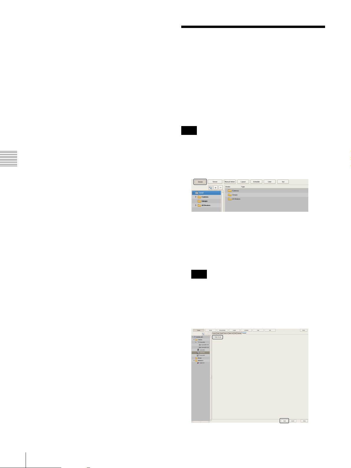
2 To configure the sound pressure detection function
on the camera, select the [Audio detection] check
box.
3 Click [Apply].
The camera tamper detection function is
configured.
Configuring Edge Storage Settings
If the camera is equipped with an Edge Storage function,
and you can configure settings for downloading the images
stored on the camera’s Edge Storage.
When this function is enabled and a video loss occurs
during a recording schedule, video is recorded to the
camera’s Edge Storage, allowing you to retrieve the data
later after the system is restored.
Note
You may need to adjust video settings to use the Edge
Storage function. For details, refer to the release notes for
the camera.
Chapter 4
Application Settings
1
Click [Device] at the top of the Configuration screen.
The Device Configuration screen appears.
2
Select the camera from the [Device] tree structure on
the left side of the screen.
You can also select multiple cameras at once by
holding down the Shift key or Ctrl key while selecting.
Note
If you selected multiple cameras and one or more of
the cameras do not support Edge Storage, the [Storage]
tab will not appear.
3
On the [Storage] tab, select the [Edge Storage] check
box, and click [Apply].
62
Configuring Edge Storage Settings
The Edge Storage function is configured.
Page 63

Configuring Settings
1
4
Related to Storage
You can configure settings for storage in the storage
location for image data and audio data of cameras.
You can configure up to 32 storage items, and configure
settings such as the maximum size of the recording file for
each storage item.
In addition, there are the following modes for storage, and
you can classify and save recording data.
• [Record Type] Mode
You can specify storage for each recording type, such as
schedule recording and alarm recording.
• [Camera] Mode
You can specify storage for saving recording data for
each camera.
4
Select the location to add as storage, and click [OK].
The storage is added to the list.
5
Configure each item, and click [Apply].
Chapter 4
Configuring Storage Settings
Add new storage, and specify the recording data to save to
the storage.
Storage can be added as individual logical volumes.
Adding New Storage
1
Click [Server] at the top of the Configuration window.
The Server Configuration screen appears.
2
Select the server for which you want to set the storage
from the [Server] tree on the left of the screen.
2
3
For details on each of the items, refer to “Setting Items
of the [Storage] Tab” (page 64).
1 Select the configured storage.
2 Enter a name for the storage.
3 Configure the settings related to overwriting data,
as necessary.
4 Click [Apply].
The storage is added.
Application Settings
3
Click (Add Storage) on the right of the list on the
[Storage] Tab.
The Add Storage dialog box appears.
Configuring Settings Related to Storage
63
Page 64

Configuring Storage for Each Recording
1 2
3
2 1 3
A
Type ([Record Type] Mode)
You can specify storage for each recording type, such as
manual recording, schedule recording, and alarm
recording.
1
Select the server for which you want to configure
storage from the [Server] tree, and click the [Storage
Assign] tab.
2
Configure each item, and click [Apply].
Chapter 4
2
Configure each item, and click [Apply].
4
For details on each of the items, refer to “Setting Items
of [Storage Assign] Tab” (page 65).
1 Select [Camera].
Application Settings
For details on each of the items, refer to “Setting Items
of [Storage Assign] Tab” (page 65).
1 Select [Record Type].
2 Select storage for each recording type.
3 Click [Apply].
Storage is set for each recording data.
Configuring Storage for Each Camera
([Camera] Mode)
You can specify storage for saving recording data for each
camera.
It is possible to save all recording data to one storage, and
specify storage for saving for each recording type.
1
Select the server for which you want to configure
storage from the [Server] tree, and click the [Storage
Assign] tab.
2 Select the default storage.
3 Select storage for each camera.
4 Click [Apply].
Storage is set for each recording data.
Setting Items of the [Storage] Tab
This tab is displayed by clicking [Server] in the
[Configuration] window, and clicking the [Storage] tab.
After configuring each item, click [Apply].
B
C
D
E
64
Configuring Settings Related to Storage
G H IF
Page 65

A Storage List
A
This displays a list of the storage configured for the server
selected in the [Server] tree.
I Close
This closes the screen.
Name
This displays the name of the storage.
Capacity (%)
This displays the capacity of the storage.
Free (%)
This displays the amount of free space as a percentage.
Free
This displays the amount of free space.
Total
This displays the total size of this storage.
B (Add Storage)
This adds new storage.
C (Delete Storage)
This deletes the storage selected in the list.
Caution
If you delete storage, all of the internal data will be lost.
D Name
Enter a name for the storage selected in the list.
Setting Items of [Storage Assign] Tab
This tab is displayed by clicking [Server] in the
[Configuration] window, and clicking the [Storage
Assign] tab.
After configuring each item, click [Apply].
Chapter 4
Application Settings
A Storage Mode
Select the method for specifying recording data for saving
to storage.
The setting items vary depending on this selection.
E Location
This displays a location (path) for saving the recording
data.
This item cannot be changed.
F Overwrite
Set this option to delete data from the oldest, regardless of
how many days it has been stored, to ensure storage space
is available.
Enable
Select the check box to enable the data overwrite
function.
The data is deleted automatically beginning with files
within the oldest record whenever the amount of free
space of the storage will fall below a specified size.
Not to be less than
Enter the minimum limit for free space as a percentage
or in gigabytes.
G Apply
This saves the settings.
H Cancel
This cancels the changes to the settings.
Record Type
Select this to specify storage for each recording type,
such as schedule recording and alarm recording.
Camera
Select this to specify storage for saving recording data
for each camera.
xTo assign storage for each recording type
B Record Type and Storage
Select storage for each recording type.
B
C D E
Configuring Settings Related to Storage
65
Page 66

Manual Record
Select storage for saving for manual recording.
Manual Record
Select storage for saving for manual recording.
Schedule Record
Select storage for saving for schedule recording.
Alarm Record
Select storage for saving for alarm recording.
Event Record
Select storage for saving for event recording.
Edge Storage Record
Select storage for saving the recorded data retrieved
from the camera’s Edge Storage.
C Apply
This saves the settings.
D Cancel
This cancels the changes to the settings.
Chapter 4
E Close
This closes the screen.
Application Settings
xTo assign storage for each camera
B
Schedule Record
Select storage for saving for schedule recording.
Alarm Record
Select storage for saving for alarm recording.
Event Record
Select storage for saving for event recording.
Edge Storage
Select storage for saving the recorded data retrieved
from the camera’s Edge Storage.
D Apply
This saves the settings.
E Cancel
This cancels the changes to the settings.
F Close
This closes the screen.
Configuring Settings Related to Deleting Recording Data
C
D E F
B Default Storage
Select the default save location for recording data.
C Storage for Each Camera and Record Type
Specify storage for each camera and recording type.
Click the setting item, and select from the list that appears.
Camera
This displays a list of the cameras registered to NSR.
This item cannot be changed.
All Record Type
Select storage for when recording the recording data of
all recording types to one storage.
When specifying storage for each recording type,
select [Select Each].
There are the following methods for deleting recording
data saved to storage.
• Data Overwriting (page 66)
Delete data from the oldest automatically, regardless of
how many days it has been stored, to ensure storage
space is always available.
• Cleanup (page 67)
Set the number of days to store recording data, and
automatically delete data that exceeds that number of
days.
• Deleting Manually (page 110)
Specify recording data for deletion manually.
Data Overwriting
Delete data from the oldest automatically, regardless of
how many days it has been stored, to ensure storage space
is always available. You can set overwriting for each
recording location.
Caution
• Estimate enough storage space to record the images you
want to save before you configure the minimum value.
However, if the minimum value is set low, the
performance may be reduced. We recommend setting
the value to 20% or more when an optional NSBK-DH05
will be installed, and to 10% or more when one will not
be installed.
66
Configuring Settings Related to Storage
Page 67

• When the data overwrite function is enabled and a file
1
432
21
currently being played back falls under the conditions
for deletion, playback of that file stops and the file is
deleted.
• If data overwriting is performed for the recording data of
a normal recording, multiple files within one record will
be deleted at one time, which may result in only the
recording of a certain camera being deleted at one time.
Configuring the following setting allows you to more
uniformly delete the recording data of multiple cameras.
– In the recurrent schedule of the normal recording,
insert at least a 1-second break each day.
Example: Start time: 00:00:00 End time: 23:59:59
1
Select the server for which you want to configure
storage from the [Server] tree, and click the [Storage]
tab.
2
Configure each item on the [Data Cleanup] tab, and
click [Apply].
3
2
Configure each item, and click [Apply].
1 Select the storage you want to configure.
2 Select the [Enable] check box.
3 Enter the minimum limit for free space as a
percentage or in gigabytes.
4
For details on each of the items, refer to “Setting Items
of the [Data Cleanup] Tab” (page 68).
1 Select the [Enable] check box.
2 Configure the time for performing the cleanup.
3 Select the check boxes of the cameras to be target
for the cleanup, and configure the number of days
to store each type of recording data.
To configure the same settings for all cameras,
click [Input All] and configure the number of
storage days in the Input All dialog box that
appears.
Chapter 4
Application Settings
4 Click [Apply].
Overwriting is configured.
Cleanup
To ensure storage space is available, set the number of
days to store recording data, and automatically delete data
that exceeds that number of days. You can configure the
same number of storage days for all cameras, or configure
the settings separately for each camera.
1
Select the server for which you want to configure
storage from the [Server] tree.
4 Click [Apply].
The cleanup is configured.
Configuring Settings Related to Storage
67
Page 68

Setting Items of the [Data Cleanup] Tab
BA
E F G
This tab is displayed by clicking [Server] in the
[Configuration] window, and clicking the [Data Cleanup]
tab.
After configuring each item, click [Apply].
Edge Storage (days)
Enter the number of storage days for Edge Storage
recording.
E Apply
This saves the settings.
F Cancel
This cancels the changes to the settings.
Chapter 4
A Enable
Application Settings
Select the check box to enable the cleanup function.
B Execution Time
Configure the time for executing the cleanup.
C Input All
Display the Input All dialog box for configuring the same
settings for all cameras.
D Cleanup Setting List
This displays a list of the cleanup settings.
C
D
G Close
This closes the screen.
Target
Select the check boxes of the cameras to be the targets
for the cleanup.
Name
This displays a list of the names of the cameras
registered to NSR.
Manual (days)
Enter the number of storage days for manual
recording.
Schedule (days)
Enter the number of storage days for schedule
recording.
Alarm (days)
Enter the number of storage days for alarm recording.
Event (days)
Enter the number of storage days for event recording.
68
Configuring Settings Related to Storage
Page 69

Configuring Recording Schedules
segmented, it will be displayed as a different record in
searches and the like.
1) The number 10,000 is the total number of files since
recording started. It includes files that are deleted with
the cleanup and data overwrite functions.
You can configure a recording schedule for each camera to
perform recording at regular intervals, and start recording
when an alarm or event occurs.
There are the following types of schedule.
• Schedule Recording (Normal Recording)
This records images from cameras according to the set
schedule.
• Alarm Recording
This begins recording only when an alarm occurs within
the time set for the schedule.
• Event Recording
This begins recording only when an event occurs within
the time set for the schedule.
You can use the following procedures to configuring
schedules.
• Configuring Schedules Manually (page 69)
You can manually configure the durations for
performing schedule recording, alarm recording, and
event recording. The duration setting methods are
“recurrent schedule,” which allows you to repeat
schedules weekly, and “date & time schedule,” which
allows you to specify specific dates and times to run
schedules.
• Configuring Alarm Recording/Event Recording
(page 71)
You can configure an alarm recording/event recording to
begin recording only when an alarm or event occurs
within the duration configured for the schedule.
Caution
The time period segmented will differ depending on the
frame rate and resolution.
Example:
Conditions Codec:
Resolution:
Frame rate:
Image quality:
Time until segmentation Approx. 19 days
When recording continuously over long periods, we
recommend segmenting the record by setting a recording
schedule that inserts a 1-second recording break each day.
For details, refer to “Configuring Schedules Manually”
(page 69).
JPEG
VGA
10 fps
Level 5
Configuring Schedules Manually
You can manually configure the durations for performing
schedule recording, alarm recording, and event recording.
Note
For details on settings such as the codec and frame rate for
images captured from the camera during schedule
recording, alarm recording, or event recording, refer to
“Configuring Camera Video Settings” (page 41).
Configuring Recurrent Schedules
You can configure a recurrent schedule to repeat a
schedule weekly.
Chapter 4
Application Settings
Before you set alarm recording or event recording,
configure the inputs that will be the alarm triggers and the
motion detection function. For the setting procedure, refer
to “Configuring Motion Detection Settings” (page 59) and
“Configuring Sensor Inputs” (page 76).
Record Segmenting in Continuous Longterm Recording
When you record continuously over a long period (such as
from 00:00 to 24:00 every day for a long time), the number
of configuration files for a record may exceed 10,000
When this happens, the record is segmented, and
subsequent data is recorded as a new record. If a record is
1)
.
1
Select the camera for which you want to configure the
schedule from the [Schedule] tree of the Schedule
screen.
You can also select multiple cameras at once by
holding down the Shift key or Ctrl key while selecting.
To display only the schedules that are common to all
the cameras selected in the left camera tree, select the
[Common Schedule Display] check box.
Configuring Recording Schedules
69
Page 70

2
2
5
1
2
5
1
Click [Recurrent] to switch to recurrent view, and
click [New Record].
The New Record dialog box appears.
3
Configure each item, and click [OK].
The setting items differ depending on the type of
schedule.
Screen example: When schedule recording
For details on how to view the schedule, refer to “Setting
Items of Schedule Screen” (page 73).
Configuring a Schedule for a Specific Date
and Time
You can configure a schedule for a specific date and time
to specify a date and time to run a schedule. The only
difference from a recurrent schedule is the procedure for
specifying a start and end date and time.
1
Select the camera for which you want to configure the
schedule from the [Schedule] tree of the [Schedule]
screen.
You can also select multiple cameras at once by
holding down the Shift key or Ctrl key while selecting.
Chapter 4
Application Settings
For details on each of the items, refer to “Setting Items
of New Record Dialog Box” (page 74).
1 Enter a name for the schedule.
2 Select the type of schedule.
3 Select the check boxes for the days you want to run
the schedule, and configure a start time and end
time for the schedule.
4 Configure each item, as necessary.
For details on the setting procedure for alarm
recording and event recording, refer to
“Configuring Alarm Recording and Event
Recording” (page 71).
5 Click [OK].
The schedule is created.
3
4
2
Click [Date Time] to switch to date and time view, and
click [New Record].
The New Record dialog box appears.
3
Configure each item, and click [OK].
The setting items differ depending on the type of
schedule.
Screen example: When schedule recording
3
4
4
Click [Apply].
The schedule is saved.
70
Configuring Recording Schedules
Page 71

For details on each of the items, refer to “Setting Items
1862
of New Record Dialog Box” (page 74).
1 Enter a name for the schedule.
2 Select the type of schedule.
3 Configure the start date and time and end date and
time to apply the schedule.
2
Click [Recurrent] or [Date Time] to switch to the view
of the schedule you want to configure, and click [New
Record].
4 Configure each item, as necessary.
For details on the setting procedure for alarm
recording and event recording, refer to
“Configuring Alarm Recording and Event
Recording” (page 71).
5 Click [OK].
The schedule is created.
4
Click [Apply].
The schedule is saved.
For details on how to view the schedule, refer to “Setting
Items of Schedule Screen” (page 73).
Configuring Alarm Recording and Event Recording
You can configure alarm recording or event recording to
begin recording only when an alarm occurs within the time
set for the schedule.
The New Record dialog box appears.
3
Configure each item, and click [OK].
The settings items differ depending on the type of
schedule.
Screen Example: When alarm recording (recurrent
schedule)
3
4
5
7
Chapter 4
Application Settings
For details, refer to “About Relationship Between Sensor
and Camera when Alarm Occurs” (page 72).
1
Select the camera for which you want to configure the
schedule from the tree in the [Schedule] screen.
You can also select multiple cameras at once by
holding down the Shift key or Ctrl key while selecting.
For details on each of the items, refer to “Setting Items
of New Record Dialog Box” (page 74).
1 Select [Alarm Record] or [Event Record].
2 Enter a name for the schedule.
3 Configure the days and time to run the schedule, or
configure the period to run the schedule.
4 Specify a condition to start recording and a
condition to end recording, and configure the
recording duration.
5 In the case of event recording, select [Record by
each event] or [Record by selected event].
• When [Record by each event] is selected, the
input pin of the selected camera itself is the
trigger to begin recording.
• When [Record by selected event] is selected, all
set input pins are triggers, and recording begins
on all selected cameras.
Configuring Recording Schedules
71
Page 72

For details, refer to “About Relationship Between
Sensor and Camera when Alarm Occurs” (page 72).
About Relationship Between Sensor and
Camera when Alarm Occurs
6 When [Record by each event] is selected, configure
the input pin of the camera or I/O device that will
be the trigger for alarm recording or event
recording.
7 Configure the camera to record images.
8 Click [OK].
The schedule is created.
4
Click [Apply].
The schedule is saved.
For details on how to view the schedule, refer to “Setting
Items of Schedule Screen” (page 73).
Chapter 4
Changing Settings
1
Application Settings
Select the camera you want to change the settings of
from the [Schedule] tree on the Schedule
Configuration screen.
2
Switch to recurrent view or date view.
When [Record by each event]:
The input pin of the selected camera itself triggers the
beginning of recording.
For example, if camera A and camera B are selected as the
cameras for recording images, and motion detection of
camera A and sensor input of camera B are configured as
the triggers, recording begins on camera A when motion
detection occurs for camera A, and recording begins on
camera B when sensor input turns on for camera B.
Recording begins on a camera whose input pin turns on.
3
Select the time slot (recurrent view) or schedule (date
view) for which you want to change the settings, and
click [Edit].
The Schedule Configuration dialog box appears.
4
Reconfigure each item.
For details on each of the items, refer to “Setting Items
of New Record Dialog Box” (page 74).
5
Click [Apply].
The settings are saved.
Deleting a Schedule
1
Select the schedule you want to delete from the
[Schedule] tree on the Schedule Configuration screen.
2
Click [Remove].
A confirmation message appears.
3
Click [Yes].
When [Record by selected event]:
All set input pins are configured as triggers to begin
recording. Recording begins on all selected cameras
regardless of which input pin turns on.
For example, if camera A and camera B are selected as the
cameras for recording images, and motion detection of
camera A and sensor input of camera B are configured as
the triggers, recording begins on both cameras even when
motion detection occurs for camera A and even when
sensor input turns on for camera B.
Recording begins on all selected cameras regardless of which
input pin turns on.
NSR
POWER 12 3NETWORK 12 34HDD 123 4 ERRORSTATUS REC
or or
or
or
The schedule is deleted.
72
Configuring Recording Schedules
or
Page 73

Setting Items of Schedule Screen
C DBA
K
IJ
This screen is displayed by clicking [Schedule] in the
Configuration window.
Screen example: When recurrent schedule (recurrent
view)
E
F
G
H
A [Schedule] Tree
This displays a list of the cameras.
Selecting cameras from the tree displays the configured
schedule in the area on the right.
• Guide lines are shown in 15-minute intervals, and by
dragging the edges of each scheduled time slot, you
can change the start and end times of the action.
When you want to configure the time in detail, click
[Edit] and make adjustments in the Schedule
Configuration dialog box that appears.
• Selecting each time slot displays information such as
the camera target for recording and the duration in
area H.
Chapter 4
When date and time view:
In this view, a list of the schedules that have been
configured are displayed.
Application Settings
B Recurrent/Date and Time View Selection
Button
Recurrent
Switches to recurrent view.
Date Time
Switches to date and time view.
C New Record
This displays the New Record dialog box (page 74) for
creating a new schedule manually.
D Common Schedule Display
Select the check box to display the schedules common to
each of the cameras.
E Schedule View
This displays the details of the schedule.
When recurrent view:
In this view, schedule items are color-coded by action
for each day of the week.
• Selecting each schedule displays information such
as the camera target for recording and the duration in
area H.
F Edit
This displays the Schedule Configuration dialog box for
changing schedule settings.
G Remove
This deletes the selected schedule.
H Show Configuration Information
This displays the configuration information of the selected
schedule.
I Apply
This saves the settings.
J Cancel
This cancels the changes to the settings.
K Close
This closes the screen.
Configuring Recording Schedules
73
Page 74
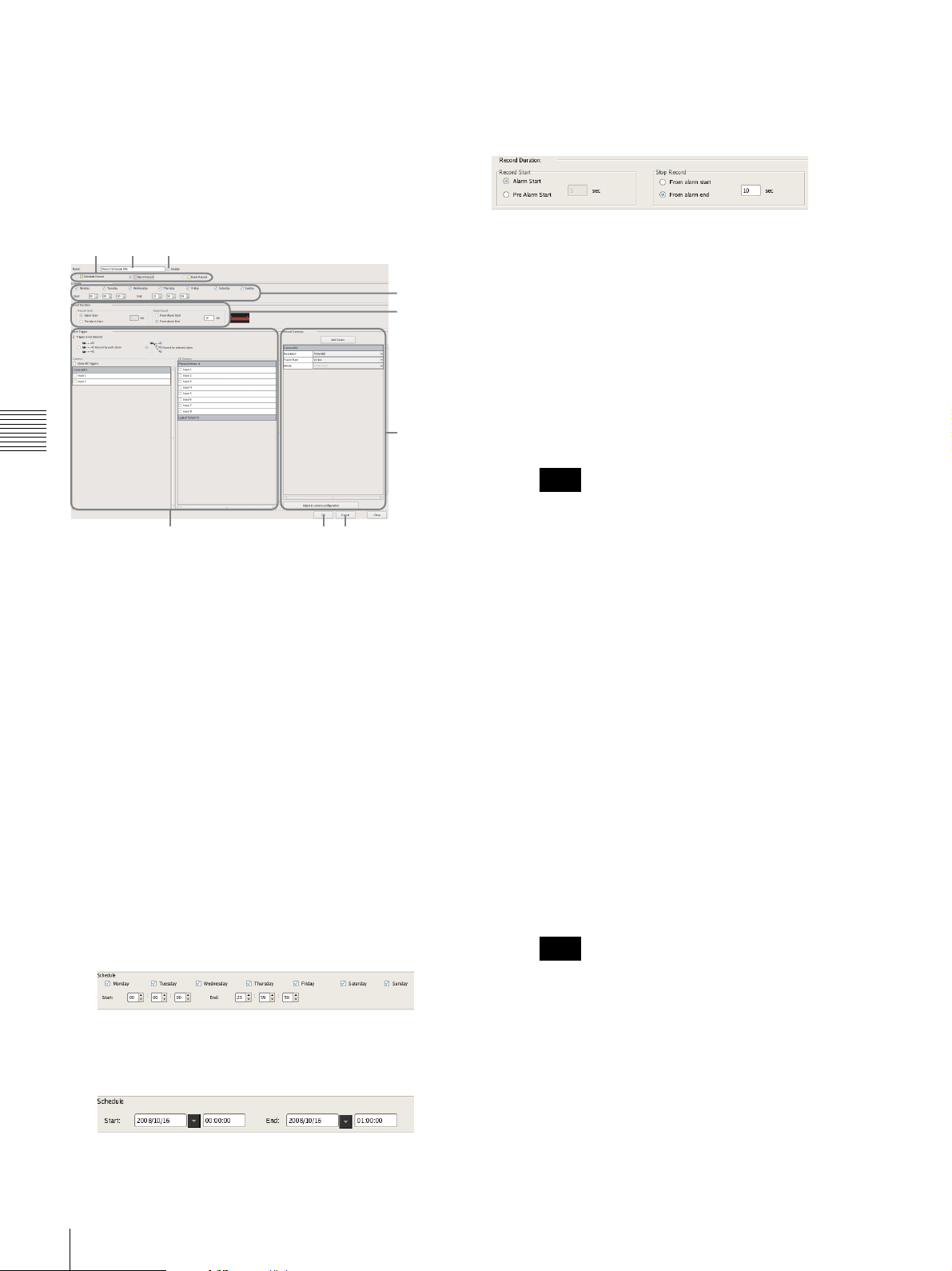
Setting Items of New Record Dialog Box
A
B C
This dialog box is displayed by clicking [New Record] on
the Schedule screen (page 74).
The items that are displayed differ depending on the type
of recording.
After configuring each item, click [OK].
E Record Duration
This item is displayed in the case of alarm recording or
event recording.
Set the record duration for when an event occurs.
Screen Example: When alarm recording (recurrent schedule)
Chapter 4
Application Settings
IG J
A Schedule Record/Alarm Record/Event Record
Select the type of schedule to configure.
B Name
Enter the name of the schedule. It can be up to 32
characters long.
C Enable
Select the check box to enable this schedule.
D Schedule
The settings differ depending on whether you are
configuring a recurrent schedule or a schedule for a
specific date and time.
When recurrent schedule:
Select the check boxes for the days you want to run the
schedule, and configure a start time and end time for
the schedule.
The range that can be specified is 00:00:00 to 23:59:59
(hours/minutes/seconds).
D
EF
H
Record Start
Select the timing for starting recording.
Alarm/Event Start
This starts recording when an alarm or event started
(point in time the alarm signal became active).
Pre Alarm/Event Start
This goes back to record the images before an alarm
or event started.
When this is selected, enter the period to go back to
record within the range of 1 to 60 seconds.
Note
Pre alarm/event start recording cannot be
performed for audio.
Record End
Select the timing for ending recording.
From Alarm/Event Start
This ends recording at the point in time a specified
period of time elapses after an alarm or event
started (point in time the alarm signal became
active).
When this is selected, enter the period for after the
alarm or event starts within the range of 1 to 3,600
seconds.
From Alarm/Even End
This ends recording when the specified duration
has passed after the point in time the alarm or event
ends (point in time the alarm is cancelled).
If you select this option, enter a duration (1 to 3,600
seconds) for which recording continues after the
alarm or event ends.
Note
When schedule for a specific date and time:
Configure the start date and time and end date and time
to apply the schedule.
74
Configuring Recording Schedules
If the camera properties for alarm recording or
regular recording are different from the camera
properties for monitoring, the camera image will
stop updating for several seconds when recording
starts and stops. Be sure to confirm your settings
before operation.
Page 75

F Associate recording data with alarm
This item is displayed for schedule recording.
Select the check box to associate the recording data with
the alarm.
If you enable association and perform an alarm search, you
can search for scheduled recordings that exist at the
moment the alarm was triggered.
If you enable association, configure the input connectors
of the camera or I/O device that will act as the alarm
trigger.
G Alarm/Event Trigger
Select the relationship of the camera for recording and the
sensor, and select the check box of the input to be the
alarm/event trigger.
For details on the relationship of the camera and sensor,
refer to “About Relationship Between Sensor and Camera
when Alarm Occurs” (page 72).
Record by each alarm/event
The camera and sensor form a one-to-one relationship.
Recording is started only for the camera of the sensor
that detected the alarm/event.
Record by selected alarm/event
Multiple inputs can be set for the one camera that is the
target for recording. Since recording can be started by
an input signal (alarm/event) from an external device
to an I/O device, it is also possible for the sensor of a
device that is not set for the schedule to act as the
trigger.
Camera
Select the check box of the input to be the alarm/event
trigger.
When “Record by selected alarm/event” is selected,
you can select multiple device inputs.
If the check box for “Show All Triggers” is selected, a
list of all the triggers configured for NSR is displayed,
so it is also possible for the sensors of devices not
configured for the schedule to act as triggers.
Note
The input configured for each camera is displayed in
the list. For the configuring inputs, refer to
“Configuring Motion Detection Settings” (page 59)
and “Configuring Sensor Inputs” (page 76).
H Record Camera
Add the camera to become the target for recording to the
list, and configure settings related to images captured from
the camera.
Add Device
This displays the Add Device dialog box for adding a
device to the list.
Select the camera you want to add from the [Nontarget Camera] list, click [Add] to move the camera to
the [Target Camera] list, and click [OK].
Camera List
Select the image size, frame rate, and other items for
images captured from the camera, as necessary.
Adjust to Camera Settings
Match the values to those configured on the [Video]
tab in “Device Configuration.”
Note
When the time set for regular recording and alarm
recording overlap, and the resolution for regular
recording is set to 320
alarm recording is set to 640
for images captured from the camera becomes 640
× 240 dpi and the resolution for
× 480 dpi, the resolution
×
480 dpi. Normally, images captured from cameras use
the maximum frame rate and resolution values for all
actions during operation.
I OK
This creates a schedule in accordance with the set values,
and closes the dialog box.
J Cancel
This cancels your settings, and closes the dialog box.
Chapter 4
Application Settings
Configuring Recording Schedules
75
Page 76

Configuring Sensor Inputs
You can configure settings related to the sensor inputs
incorporated in NSR and cameras, and Barionet (Barix I/O
box) sensor inputs.
Sensor inputs can be specified and used for actions and
schedule recording events.
Examples of sensor inputs:
Temperature, humidity, smoke, vibration, security,
infrared, ultrasonic waves, etc.
You can configure the following settings for sensor inputs.
• “Changing Settings of Sensor Input Pins of NSR”
(page 76)
• “Changing Settings of Sensor Input Pins of Camera”
Chapter 4
(page 76)
• “Changing Settings of Sensor Input Pins of Barionet”
(page 77)
• “Adding Logical Sensor Input Pins to NSR” (page 77)
Application Settings
• “Deleting Logical Sensor Input Pins Created for NSR”
(page 78)
3
Configure each item on the [Physical Sensor In] tab,
and click [Apply].
For details on each of the items, refer to “Setting Items
of the [Logical Sensor In] Tab” (page 78).
The sensor input settings are changed.
Changing Settings of Sensor Input Pins of Camera
Changing Settings of Sensor Input Pins of NSR
1
Click [Device] at the top of the Configuration window.
The Device Configuration screen appears.
2
Open [I/O Device] in the [Device] tree, and click to
select [System I/O].
1
Click [Device] at the top of the Configuration window.
The Device Configuration screen appears.
2
Select the camera you want to change the settings of
the sensor input pins from the [Device] tree.
3
Configure each item on the [Sensor In] tab, and click
[Apply].
76
Configuring Sensor Inputs
Page 77

For details on each of the items, refer to “Setting Items
12
of the [Logical Sensor In] Tab” (page 78).
The sensor input settings are changed.
Changing Settings of Sensor Input Pins of Barionet
Caution
• Barionet cannot be used via a proxy server.
• Manually perform device registration for Barionet
before configuring the following settings.
• For details, refer to the operating manual for Barionet.
1
Click [Device] at the top of the Configuration window.
The Device Configuration screen appears.
Adding Logical Sensor Input Pins to NSR
The adding of a logical sensor input pin to NSR allows for
linking with the external device via the network. The
operation (on/off) of the added sensor input pin from the
external device acts as a trigger to perform recording or an
action.
1
Click [Device] at the top of the Configuration window.
The Device Configuration screen appears.
2
Open [I/O Device] in the [Device] tree, and click to
select [System I/O].
Chapter 4
Application Settings
2
Open [I/O Device] in the [Device] tree, and click to
select [Barionet].
3
Configure each item on the [Sensor In] tab, and click
[Apply].
3
Add the logical sensor input pin on the [Logical Sensor
In] tab.
3
For details on each of the items, refer to “Setting Items
of the [Logical Sensor In] Tab” (page 78).
For details on each of the items, refer to “Setting Items
of the [Logical Sensor In] Tab” (page 78).
The Barionet sensor input settings are changed.
1 Click [Add].
The logical sensor input pin is added to the list.
2 Configure each item.
Configuring Sensor Inputs
77
Page 78
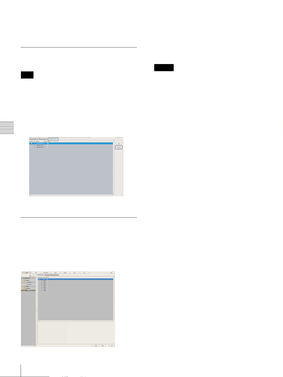
3 Click [Apply].
The logical sensor input pin is added.
Deleting Logical Sensor Input Pins Created for NSR
Note
The physical sensor input pins of NSR that exist by default
cannot be deleted.
1
Open [I/O Device] in the [Device] tree, and click to
select [System I/O].
2
Select the check boxes for the logical sensor input pins
you want to delete in the [Logical Sensor In] tab, and
Chapter 4
Application Settings
click [Delete].
Sensor Input Pin List
This displays a list of the sensor input pins configured for
the device selected in the tree structure.
Enable
Select the check boxes to enable the pins for the sensor
inputs.
Caution
To use sensor inputs, the sensor input pin settings on
the device must also be enabled.
No
This displays the numbers of the sensor input pins.
This item cannot be changed.
Name
Enter the names of the sensor inputs.
Pulse
Enter the duration to sustain pulse input once it is
turned on within the range of 0 to 60,000 milliseconds.
If pulses of short duration persist and there is a high
frequency of on/off switching as a result of this
configuration, multiple inputs may be grouped
together as one pulse.
The logical sensor input pin is deleted.
Setting Items of the [Logical Sensor In] Tab
You can configure sensor input pins.
After configuring each item, click [Apply] to save your
settings.
This example describes the screen for configuring logical
sensor input pins of the NSR.
Invert
Select the check box to invert the pulse polarity.
Example: Invert ON → OFF to OFF → ON.
Add
This adds a logical sensor input pin to the list.
This item is only displayed for the logical sensor inputs of
“System I/O.”
Delete
This deletes the selected sensor input pin from the list.
This item is only displayed for the logical sensor inputs of
“System I/O.”
78
Configuring Sensor Inputs
Page 79

Configuring Alarm Output Settings
You can configure settings related to the alarm outputs
incorporated in NSR and cameras, and Barionet (Barix I/O
box) alarm outputs.
Outputs are used to transmit alarms to devices equipped
with alarm input functions, such as warning lamps and
door opening devices.
Example of Alarm Outputs:
Warning siren, warning lamp, light, door, etc.
You can configure the following settings for alarm
outputs.
• “Changing Settings of Alarm Output Pins of NSR”
(page 79)
• “Changing Settings of Alarm Output Pins of Camera”
(page 79)
• “Changing Settings of Alarm Output Pins of Barionet”
(page 80)
Changing Settings of Alarm Output Pins of NSR
3
Configure each item on the [Physical Alarm Out] tab,
and click [Apply].
For details on each of the items, refer to “[Alarm Out]
Tab (I/O Device)” (page 80).
The alarm output settings are changed.
Changing Settings of Alarm Output Pins of Camera
1
Click [Device] at the top of the Configuration window.
Chapter 4
Application Settings
1
Click [Device] at the top of the Configuration window.
The Device Configuration screen appears.
2
Open [I/O Device] in the [Device] tree, and click to
select [System I/O].
The Device Configuration screen appears.
2
Select the camera you want to change the settings of
the alarm output pins from the [Device] tree.
Configuring Alarm Output Settings
79
Page 80

3
Configure each item on the [Alarm Out] tab, and click
[Apply].
3
Configure each item on the [Alarm Out] tab, and click
[Apply].
For details on each of the items, refer to “[Alarm Out]
Tab (Camera)” (page 81).
Chapter 4
Application Settings
The alarm output settings are changed.
Changing Settings of Alarm Output Pins of Barionet
Caution
• To use the alarm outputs of Barionet, it is necessary to
connect to Barionet from a Web browser and enable the
alarm output settings in advance.
• Barionet cannot be used via a proxy server.
• Manually perform device registration for Barionet
before configuring the following settings.
• For details, refer to the operating manual for Barionet.
1
Click [Device] at the top of the Configuration window.
For details on each of the items, refer to “[Alarm Out]
Tab (I/O Device)” (page 80).
The Barionet alarm output settings are changed.
Setting Items of the [Alarm Out] Tab
[Alarm Out] Tab (I/O Device)
You can configure the alarm output pins of NSR and
Barionet.
After configuring each item, click [Apply] to save your
settings.
This example describes the screen for configuring alarm
outputs of NSR.
The Device Configuration screen appears.
2
Open [I/O Device] in the [Device] tree, and click to
select [Barionet].
80
Configuring Alarm Output Settings
Alarm Output Pin List
This displays a list of alarm output pins configured for the
NSR or Barionet selected in the tree.
Enable
Select the check boxes to enable the pins for the alarm
outputs.
No
This displays the numbers of the alarm output pins.
This item cannot be changed.
Page 81

Caution
To use alarm outputs, the alarm output pin settings on
the device must also be enabled.
Name
Enter the names of the alarm outputs. They can be up
to 32 characters long.
Name
Enter the names of the alarm outputs. They can be up
to 32 characters long.
Pulse
Select the check box when you want to specify and
enter a pulse interval. If you select this, enter the pulse
interval in [Pulse Duration].
Pulse
Select the check box when you want to specify and
enter a pulse interval. If you select this, enter the pulse
interval in [Pulse Duration].
Pulse Duration
Enter the duration to sustain pulse output once it is
turned on within the range of 0 to 60,000 milliseconds.
Invert
Select the check box to invert the polarity of the output
pins.
Enabling invert does not change the state of the current
output pins. If you turn the output pins on/off when
they are in an inverted state, the actual output signal
state is inverted to off/on.
Also, in the case of output pins of the NSR unit, state
initialization is performed according to the invert
setting at startup.
(When inverted: On at startup, When not inverted: Off
at startup)
[Alarm Out] Tab (Camera)
You can configure the alarm output pins of the camera
selected in the tree.
After configuring each item, click [Apply] to save your
settings.
Pulse Duration
Enter the duration to sustain pulse output once it is
turned on within the range of 0 to 60,000 milliseconds.
Invert
Select the check box to invert the polarity of the output
pins.
Enabling invert does not change the state of the output
pins. If you turn the output pins on/off when they are
in an inverted state, the actual output signal state is
inverted to off/on.
Preview
This displays the images captured from the camera.
Chapter 4
Application Settings
Alarm Output Pin List
This displays a list of the alarm output pins configured for
the camera selected in the tree.
Enable
Select the check boxes to enable the pins for the alarm
outputs.
No
This displays the numbers of the alarm output pins.
This item cannot be changed.
Configuring Alarm Output Settings
81
Page 82

Configuring Action
1 2
3
Settings
In NSR, you can configure the action for when, for
example, a sensor input, VMD (camera) or system alarm is
detected, or for when a manual action is performed.
Relationship Between Events and Actions
2
Click (Add).
3
Configure the following items, and register the action.
When an event such as an
alarm occurs...
Camera sensor input
VMD (Camera)
Hardware error
System alart
Chapter 4
Manual trigger
etc.
Application Settings
Events Actions
The action corresponding
to the event is performed.
Camera alarm output
Sending e-mail
Switching layput
Beep sound
etc.
There are the following way of configuring actions.
• Manual Actions (page 82)
Configure an action for when a trigger occurs manually.
• Event/Alarm Actions (page 85)
Configure an action for when an alarm or event occurs
during a specified schedule period.
Manual Action
Configure an action for when a trigger occurs manually.
For details on each of the items, refer to “Setting Items
of Manual Action Screen” (page 83).
1 Enter a name for the action.
2 Configure each item.
3 Click [Apply].
The action is registered.
Registering a Manual Action
1
Click [Manual Action] at the top of the Configuration
window.
The Manual Action screen appears.
82
Configuring Action Settings
Page 83

Performing a Manual Action
You can perform an action from the Manual Action toolbar
in the main window.
1
Display the Manual Action pane in the main window.
Click in the pane at the top right of the screen, and
select [Manual Action] from the menu that appears.
2
Select the action you want to perform, and click
[Perform].
Setting Items of Manual Action Screen
You can configure manual action settings.
The items that are displayed differ depending on the device
for performing the action.
After configuring each item, click [Apply] to save your
settings.
Name
Enter the name of the action. It can be up to 32 characters
long.
Chapter 4
Application Settings
A confirmation message appears.
3
Click [OK].
Show on the Main Window
Select the check box to show this layout in the [Manual
Action] pane of the main window.
Register as OFF Action
Select the check box to register an action as an off action.
Off actions operate as shown below.
Tour: Stops the tour
Alarm Output: Turns off alarm output
Beep: Stops the beep
[Camera Action] Tab
Number of Settings
This displays the number of cameras target for the
action.
The action is performed.
[Add Device] Button
This displays a dialog box for adding a camera as a
target for the action.
Camera Drop-down Menu
Select a camera.
Configuring Action Settings
83
Page 84

Camera Control
Select the check box to perform an action for
controlling the camera, and specify the control
method.
Preset
This moves the camera to the specified preset
position.
Tour
This performs the specified camera tour.
Action End Preset
Specify the preset position for when the action
ends.
Pin List
Select the check boxes for the pins to be target for
performing an action to change the pin state.
[I/O Device Action] Tab
Chapter 4
[System Action] Tab
Send e-mail
Select the check box to send a notification by mail to a
specified mail address.
E-mail Address
Enter an e-mail address.
Application Settings
Number of Settings
This displays the number of I/O devices target for the
action.
[Add Device] Button
This displays a dialog box for adding an I/O device as
a target for the action.
I/O Device Drop-down Menu
Select the I/O device.
Pin List
Select the check boxes of the pins for which to change
the state.
Attach Camera Image
Select the check box to send a still image as a mail
attachment.
If you select this, specify the camera for recording the
still image.
Note
Images will not be attached for cameras on which the
codec is MPEG4/H.264.
Each camera
Attach the still images recorded with the camera for
which the event occurred.
For example, when motion detection of camera A and
sensor input of camera B are configured as the triggers
and motion detection occurs for camera A, the still
images recorded with camera A are attached. When
the sensor input of camera B turns on, the still images
recorded with camera B are attached.
Specified Camera
Record a still image with the specified camera.
Message
Enter the message of the mail. It can be up to 32
characters long.
84
Configuring Action Settings
Change Layout
Select the check box to change the monitor layout of
monitor 1.
If you select this, select the monitor layout to display on
monitor 1.
This item is only displayed for a server.
Page 85

Beep
0
12
24
231
1 2
Select the check box to play a beep tone.
If you select this, select a beep tone type.
This item is only displayed for a server.
The beep sound is output for a predetermined duration
from the device connected to the audio connector specified
in the Audio screen of the Setup Wizard or the Setup
Menu.
1
Click [Schedule] at the top of the Configuration
window.
The Schedule Configuration screen appears.
Apply
This saves the settings.
Cancel
This cancels the changes to the settings.
Event/Alarm Actions
An action is performed if an alarm or event occurs within
the duration set for a schedule. An action can be performed
each time an alarm or event occurs, provided it occurs
within the duration.
Caution
Even if the state changes as a result of an action being
performing, the original state is not restored automatically.
Event/Alarm Action Example:
When an event/alarm action for moving the preset position
to “Preset 2” if motion is detected by the VMD (camera)
pin of camera 1:
Alarm Recording Schedule
Preset 2Preset 2
Preset 1 Preset 2
2
Switch to recurrent view or date view.
3
Select [Action] in the tree, and select [New Action].
The New Action dialog box appears.
4
Configure each item, and click [OK].
Chapter 4
Application Settings
3
4
6
1 When the VMD (camera) pin detects motion, the
75
action is performed and the preset position of camera
1 moves to “Preset 2.”
For details on each of the items, refer to “Setting Items
of New Action Dialog Box (Event/Alarm Action)”
2 The preset position is returned to “Preset 1” manually.
3 When the VMD (camera) pin detects motion within
(page 86).
1 Select [Event/Alarm Action].
the duration, the action is performed again and the
preset position of camera 1 moves to “Preset 2.”
Registering an Event/Alarm Action
Configure a schedule for performing an action when an
2 Enter a name for the event/alarm action.
3 Select the check boxes for the days you want to run
the event/alarm action, and configure a start time
and end time for the event/alarm action.
alarm or event occurs within the duration set for the
schedule. An action can be performed each time an alarm
4 Configure the timing for ending the action.
or event occurs, provided it occurs within the duration.
5 Configure the event that will be the trigger for the
action.
6 Configure the action to perform.
Configuring Action Settings
85
Page 86

7 Click [OK].
A
The event/alarm action is created.
5
Click [Apply].
The range that can be specified is 00:00:00 to 23:59:59
(hours/minutes/seconds).
The event/alarm action is saved.
For details on how to view the schedule, refer to “Setting
Items of Schedule Screen” (page 73).
Setting Items of New Action Dialog Box
(Event/Alarm Action)
This dialog box is displayed by selecting [Action] from the
tree in the Schedule Configuration screen, and then
clicking [New Action].
After configuring each item, click [OK].
Screen example: When recurrent event/alarm
action:
Chapter 4
Application Settings
B C
D
EF
When event/alarm action for a specific date
and time:
Configure the start date and time and end date and time
to apply the event/alarm action.
E Action Duration
Configure the duration for the action.
Action Start
This displays the timing for starting the action.
This item cannot be changed.
Stop Action
Select the timing for ending the action.
From Alarm Start
This ends the action at the point in time a specified
time elapses after the alarm started.
When this is selected, enter the period for after the
alarm starts within the range of 1 to 3,600 seconds.
From Alarm End
This ends the action at the point in time a specified
time elapses after the alarm ends.
When this is selected, enter the period for after the
alarm ends within the range of 1 to 3,600 seconds.
I JHG
A Schedule Action and Event/Alarm Action
Select the type of event/alarm action to configure.
The setting items vary depending on this selection.
B Schedule
Enter the name of the event/alarm action. It can be up to 32
characters long.
C Enable
Select the check box to enable this event/alarm action.
D Schedule
The settings differ depending on whether you are
configuring a recurrent event/alarm action or an event/
alarm action for a specific date and time.
When recurrent event/alarm action:
Select the check boxes for the days you want to run the
event/alarm action, and configure a start time and end
time for the event/alarm action.
No Definition
The timing to end the action is not specified.
F Server
Select the remote server.
This item is displayed in the case of a client.
G Event
Configure the event that will be the trigger for the action.
Camera
Select the check box of the input pin to be the action
trigger.
I/O Device
Select the check box of the input pin to be the action
trigger.
Note
The input configured for each camera and I/O device
is displayed in the list. For the input pin settings, refer
to “Configuring Motion Detection Settings” (page 59)
and “Configuring Sensor Inputs” (page 76).
86
Configuring Action Settings
Page 87

System Alert
Select the check box to use a system alert as the
trigger.
Pin List
Select the check boxes for the output pins to be target
for performing an action to change the pin state.
H Action
Configure the action to perform.
Alarm Notification
Send an alarm notification for the configured trigger.
Action
This performs the specified action.
[Camera Action] Tab
[I/O Device Action] Tab
Chapter 4
Application Settings
Number of Settings
This displays the number of I/O devices target for the
action.
[Add Device] Button
This displays a dialog box for adding an I/O device as
a target for the action.
Number of Settings
This displays the number of cameras target for the
action.
[Add Device] Button
This displays a dialog box for adding a camera as a
target for the action.
Camera Drop-down Menu
Select a camera.
Camera Control
Select the check box to perform an action for
controlling the camera, and specify the control
method.
Preset
This returns the camera to the specified preset
position.
Tour
This performs the specified camera tour.
Action End Preset
Specify the preset position for when the action
ends.
I/O Device Drop-down Menu
Select the I/O device.
Pin List
Select the check boxes of the pins for which to change
the state.
[System Action] Tab
Configuring Action Settings
87
Page 88

Send e-mail
Select the check box to send a notification by mail to a
specified mail address.
I OK
This creates an event/alarm action in accordance with the
set values, and closes the dialog box.
Chapter 4
Application Settings
E-mail Address
Enter an e-mail address.
For details on mail notification settings, refer to
“Configuring Mail Notification Settings”
(page 89).
Attach Camera Image
Select the check box to send a still image as a mail
attachment.
If you select this, specify the camera for recording
the still image.
Note
If the codec of the camera is MPEG4/H.264, the
image is not attached.
Each camera
Attach the still images recorded with the camera for
which the event occurred.
For example, when motion detection of camera A
and sensor input of camera B are configured as the
triggers and motion detection occurs for camera A,
the still images recorded with camera A are
attached. When the sensor input of camera B turns
on, the still images recorded with camera B are
attached.
J Cancel
This cancels your settings, and closes the dialog box.
Specified Camera
Attach still images recorded with a specified
camera.
Message
Enter the message of the mail. It can be up to 32
characters long.
Change Layout
Select the check box to change the monitor layout of
monitor 1.
If you select this, select the monitor layout to display
on monitor 1.
Beep
Select the check box to play a beep tone.
If you select this, select a beep tone.
The beep sound is output for a predetermined duration
from the device connected to the audio connector
specified in the Audio screen of the Setup Wizard or
the Setup Menu.
Notify Emergency Event
Select the check box to enable notifications for the
specified emergency events.
88
Configuring Action Settings
Page 89

5 Enter the mail address for sending test mail.
1
7
Configuring Mail Notification Settings
When an event occurs, a notification can be sent by e-mail
to a pre-registered mail address.
You can configure a mail address for each action. Specify
the SMTP server and sender address here.
1
Click [Server] at the top of the Configuration window.
The Server Configuration screen appears.
2
Select the server for which you want to set the mail
notification settings from the [Server] tree on the left
of the screen.
6 After you enter each address, click [Send Test Mail]
and confirm that mail can be sent correctly.
7 Click [Apply].
Chapter 4
Application Settings
3
Configure each item on the [E-mail] tab, and click
[Apply].
1 Enter the address of the SMTP server.
2 Enter the port number of the SMTP server.
3 Enter the mail address of the sender.
2
4
5
6
3
4 When using SMTP authentication, select the check
box next to [Authentication], and then enter the
user name and password for SMTP authentication.
Configuring Mail Notification Settings
89
Page 90

Configuring System Alert
1
D FE
For details on actions, refer to “Configuring Action
Settings” (page 82).
Settings
A system alert (alarm) can be generated when camera
video loss or insufficient disk space is detected. Configure
the settings for the action to perform after a system alert is
generated.
1
Click [Server] at the top of the Configuration window.
The Server Configuration screen appears.
2
Select the server for which you want to set the system
Chapter 4
Application Settings
alert settings from the [Server] tree on the left of the
screen.
3
Configure the information to notify of in the system
alert on the [System Alert] tab, and click [Apply].
Setting Items of the [System Alert] Tab
This tab is displayed by clicking [Server] in the
[Configuration] window, and clicking the [System Alert]
tab.
After configuring each item, click [Apply].
A
B
C
A VIDEO LOSS
Select the check box to notify of the image signal
becoming disconnected.
Note
2
For details on each of the items, refer to “Setting Items
of the [System Alert] Tab” (page 90).
1 Select the check boxes for the notification items,
2 Click [Apply].
4
Configure the action to perform after a system alert
occurs.
and configure each item.
The settings are saved.
Disconnection of the audio signal is not a target for
detection.
Camera List
This displays a list of the video loss notification settings.
Target
Select the check boxes for the cameras to be target for
notification.
Camera Name
This displays a list of the names of the cameras
registered to NSR.
B Disk Usage
Select the check box to notify of insufficient remaining
disk space.
Target Storage List
Select the check boxes for the storage to be target for
notification.
Target
Select the check boxes for the storage to be target for
notification.
Name
This displays the storage name of the target for
notification.
90
Configuring System Alert Settings
Page 91

Capacity
This displays the capacity of the storage.
Free (%)
This displays the amount of free space as a percentage.
Free
This displays the amount of free space in gigabytes.
Total
This displays the total size of the storage.
Threshhold
Specify the threshold value for the remaining space at
which the notification will be sent.
Registering Users
You can register users in NSR, and set logon passwords
and access permissions for each function. Five levels are
provided for users ranging from the administrator level
(Level 5) to the view level (Level 1). Permissions are
granted as follows depending on the user level. You can
also configure permissions individually for each user, as
necessary.
Caution
Type
Specify GB or % for the threshold value type.
C Record Count
Select the check box to notify of the record count
exceeding a specified amount.
If you select this check box, enter the percentage of the
maximum record count that the current record count needs
to reach for notification to be sent.
Current/Max. Record Count
This displays the current record count and the
maximum record count.
D Apply
This saves the settings.
E Cancel
This cancels the changes to the settings.
F Close
This closes the screen.
Caution
The recording errors and hardware errors of NSR are
included in the system alerts, and notification always
occurs regardless of the settings.
• Only a user who has been granted the “User
Configuration” permission can perform operations such
as registering users and configuring user settings.
• If you forgot the passwords for all users with “User
Configuration” permissions, the NSR must be formatted
to enable password resetting. Current setting
configurations and recordings will not be retained if the
NSR is formatted.
User Levels and Permissions
You can set the following five levels for users.
Level 1: Allowed to view monitoring and options
windows.
Level 2: In addition to the permissions of Level 1, allowed
to perform basic operations including camera control
such as panning, tilting, and zooming, and searching
for and playing back recording images.
Level 3: In addition to the permissions of Level 2, allowed
to perform recording file operations such as managing
logs, deleting and protecting files, and exporting.
Level 4: In addition to the permissions of Level 3, allowed
to configure device settings such as registering devices
and creating layouts and schedules.
Level 5: In addition to the permissions of Level 4, allowed
to perform all operations including configuring
settings and configuring menus as an administrator.
Chapter 4
Application Settings
Permission User Level
1 2 3 4 5
User Configuration None None None None Yes
Administrator Menu
Setting
Schedule
Configuration
Device Configuration None None None Yes Yes
Server Configuration None None None Yes Yes
Layout Configuration None None None Yes Yes
GUI Configuration None None None Yes Yes
None None None None Yes
None None None Yes Yes
Registering Users
91
Page 92

Permission User Level
1
3 4 5
1 2 3 4 5
Manual Action
Configuration
Manual Deletion/
Protection
Log Control None None Yes Yes Yes
Export Control None None Yes Yes Yes
Exit Server None None Yes Yes Yes
Search & Playback None Yes Yes Yes Yes
Camera Control None Yes Yes Yes Yes
Output Control None Yes Yes Yes Yes
Layout Control None Yes Yes Yes Yes
Manual Record None Yes Yes Yes Yes
Manual Action None Yes Yes Yes Yes
Capture Control None Yes Yes Yes Yes
Display Control None Yes Yes Yes Yes
Chapter 4
Alarm History Control None Yes Yes Yes Yes
Exit Application Yes Yes Yes Yes Yes
Application Settings
None None None Yes Yes
None None Yes Yes Yes
Registering a User
3
Configure each item, and click [Apply].
For details on each of the items, refer to “Setting Items
of the [User] Tab” (page 93).
1 Enter the user name and password. They can be up
to 32 characters long and ASCII characters (upper
or lower case alphanumeric characters and symbols
(! " # $ % & ' ( ) * + , - . / : ; < = > ? @ [ \ ] ^ _ ` { |
} ~)).
2
Register the user to use NSR, and configure the
permissions.
1
Click [User] at the top of the Configuration window.
The User Configuration screen appears.
2
Select a level for the user you want to register in the
[User] tree, and click (Add).
The user is added to the tree.
2 Change the user level, as necessary.
Select “Custom” when you want to set the
permissions individually.
3 Select the check boxes for the permissions to grant
to the user.
4 To configure access permissions for each device,
select the check boxes of the devices to which to
grant access permissions.
5 Click [Apply].
The settings are saved.
Note
If “Custom” is selected for the user level, the [Custom]
tree is displayed.
92
Registering Users
Page 93

Changing User Settings
A
C D E F G
Setting Items of the [User] Tab
1
Select the user you want to change the settings of from
the [User] tree on the User Configuration screen.
2
Reconfigure the items you want to change.
For details on each of the items, refer to “Setting Items
of the [User] Tab” (page 93).
3
After configuring each item, click [Apply].
The settings are changed.
Deleting a User
1
Select the user you want to delete from the [User] tree
on the User Configuration screen.
2
Click (Delete).
A confirmation message appears.
This tab allows you to register users and configure
permissions.
It is displayed by clicking [User] in the Configuration
window.
After configuring each item, click [Apply] to save your
settings.
B
Chapter 4
Application Settings
A User Name
Enter the user name. It can be up to 32 characters long and
ASCII characters (upper or lower case alphanumeric
characters and symbols (! " # $ % & ' ( ) * + , - . / : ; < = >
? @ [ \ ] ^ _ ` { | } ~)).
3
Click [Yes].
The user is deleted.
Password
Enter the password. It can be up to 32 characters long
and ASCII characters (upper or lower case
alphanumeric characters and symbols (! " # $ % & ' ( )
* + , - . / : ; < = > ? @ [ \ ] ^ _ ` { | } ~)).
Confirm Password
Enter the same password again for confirmation.
B User Level
Select a user level.
Select “Custom” when you want to set the permissions
individually.
C Permission
Select the check boxes for the permissions to grant to the
user.
The following are the types of permissions that are
available.
User Configuration
Allows you to configure or change user accounts in the
User Configuration screen.
Administrator Menu Setting
Allows you to configure the various settings in the
Setup Menu.
Registering Users
93
Page 94

Chapter 4
Application Settings
Schedule Configuration
Allows you to add or change schedules in the Schedule
screen.
Device Configuration
Allows you to add or remove devices in the Device
Configuration screen.
Server Configuration
Allows you to configure settings related to the server
and network in the Server Configuration screen.
Layout Configuration
Allows you to register or change monitor layouts in the
Layout Configuration screen.
GUI Configuration
Allows you to configure the rewind duration for quick
playback in the GUI Configuration screen.
Manual Action Configuration
Allows you to configure the action for when a trigger
is manually activated in the Manual Action screen.
Manual Deletion/Protection
Allows you to manually delete recorded images. You
can also protect recorded images from being deleted
due to cleanup, data overwrite, or unintentional
operations.
Exit Application
Allows you to lock operations.
D Servers/Cameras Access
Select the check boxes for the devices or servers that the
user will be permitted to access.
E Apply
This saves the settings.
F Cancel
This cancels the changes to the settings.
G Close
This closes the screen.
Caution
If there is no permission to access a server, logging on to
that server is not possible.
Log Control
Allows you to export logs in the Log dialog box.
Export Control
Allows you to export recorded images.
Exit Server
Allows you to shut down or restart.
Search & Playback
Allows you to search or play back recorded data.
Camera Control
Allows you to control cameras in the Camera Control
pane.
Layout Control
Allows you to change layouts.
Manual Record
Allows you to perform manual recording.
Manual Action
Allows you to execute manual actions.
Capture Control
Allows you to export monitored or recorded images as
still images.
94
Alarm History Control
Allows you to clear alarm histories.
Registering Users
Page 95

Configuring the Duration to Rewind for Quick Playback
When you click [PLAYBACK] in the Main screen, the
selected monitor frame enters the playback state, and
playback automatically starts after rewinding a specified
duration. (This function is referred to as “quick
playback.”)
You can configure the duration to rewind for quick
playback in the GUI Configuration screen.
1
Click [GUI] at the top of the Configuration screen.
The GUI Configuration screen appears.
2
Enter the duration to rewind for quick playback in
seconds, and click [Apply].
Chapter 4
Application Settings
The duration to rewind for quick playback is
configured.
Note
You can set a time of 10 seconds or longer.
Configuring the Duration to Rewind for Quick Playback
95
Page 96

Operation and Control
Monitoring
You can monitor the live images currently being captured
by the camera, as well as the audio from the camera. You
can also perform monitoring using the layout tour function
for sequentially switching the display shown on the display
at a preset time.
This section describes the following monitoring
Chapter 5
operations.
• “Monitoring Live Images” (page 96)
• “Monitoring Using Layout Tours” (page 97)
Operation and Control
• “Monitoring Audio from Cameras” (page 97)
Note
Chapter
Live images are displayed on the selected monitor
frame.
5
To use the layout tour function, a layout tour needs to be
configured in advance. For the configuration procedure,
refer to “Configuring Layout Tours” (page 57).
Monitoring Live Images
You can monitor the images the camera is currently
capturing in any monitor frame.
1
Click the monitor frame to display the live images on
the main screen.
2
Click [LIVE] on the Monitor Control pane.
For details on each of the items, refer to “Functions
and Operating Procedure of Main Screen” (page 98).
Monitoring Images of a Different Camera
Select a camera on the Camera pane, and drag and drop it
onto the monitor frame to switch to displaying the images
of the selected camera.
You can also switch to the images of a selected camera by
clicking to select a monitor frame, and then doubleclicking a camera in the Camera pane.
96
Monitoring
Page 97

Note
When the Camera pane is not displayed, click and
select [Camera] from the menu that appears to switch to
the Camera pane.
Changing the Layout
Select a layout on the [Layout] toolbar at the top of the
main screen to change the layout.
Monitoring Audio from Cameras
If you are using a camera with support for audio input, you
can monitor the audio input from the camera.
Select the monitor frame for which you want to monitor
the audio to output audio from the camera assigned to the
selected monitor frame.
If multiple monitor frames are selected, audio is only
output from the camera of the one selected last.
Adjusting the Volume
1
Click (Adjust Volume).
The Volume Control dialog box appears.
Monitoring Using Layout Tours
You can perform monitoring using the layout tour function
for sequentially switching the display shown on the display
at a preset time.
Note
To use the layout tour function, a layout tour needs to be
configured in advance. For the configuration procedure,
refer to “Configuring Layout Tours” (page 57).
1
Select a layout tour on the [Tour] toolbar at the top of
the main screen.
2
Click (Layout Tour Start).
2
Adjust the volume with the slider, and click [OK].
When you want to disable the sound, select the
[Muting] check box.
Slider
Note
In the disable state, audio is no longer output no matter
which monitor frame you select.
Chapter 5
Operation and Control
The sequence operation starts.
If you click again, the layout tour ends.
Monitoring
97
Page 98

Functions and Operating Procedure of Main Screen
AB DC E
JKL
On the main screen, you can perform operations such as monitoring the live images captured from the current camera and
playing back recorded images.
M
F
G
H
Chapter 5
Operation and Control
A [Layout] Toolbar
Use this to change the layout.
(2×2 Layout)
This switches to the 2×2 default layout.
(3×3 Layout)
This switches to the 3×3 default layout.
(4×4 Layout)
This switches to the 4×4 default layout.
(Custom A Layout)
This switches to the layout of the Custom A group.
(Custom B Layout)
This switches to the layout of the Custom B group.
Layout Menu
Select a layout from the drop-down menu.
I
B [Tour] Toolbar
This is used when executing a layout tour.
Tour Menu
Select a layout tour from the drop-down menu.
(Layout Tour Start/Stop)
This starts or stops the layout tour.
C (Display Information)
This displays or hides the information of the monitor
frame configured in the layout settings.
98
Monitoring
Page 99

D (Search Recording Data)
This displays the Search window (page 108) for
specifying search conditions.
(Open Log Window)
This displays the [Log] window (page 116) for
displaying the recent log messages.
(Volume Control)
Adjust the volume for audio output from NSR.
The audio of the camera of the selected monitor frame
is output.
(Configuration)
This displays the Configuration window (page 37) for
configuring settings such as device registration and
camera operation.
(Full Screen)
This displays the current layout (monitor arrangement)
over the whole screen.
Switching to full screen hides the control buttons and
other items.
(Cancel Full Screen)
This returns from the full screen display to the normal
screen.
This button is displayed in full screen display when
you align the cursor with the top-right corner of the
screen.
You can also return to the normal screen by pressing
the Esc key on the keyboard.
Camera Pane
This allows you select the camera for displaying
images in the monitor frame.
Select a camera from the tree, and drag and drop it onto
the monitor frame to switch to displaying the images
of the selected camera.
Groups Pane
Chapter 5
Operation and Control
E
This allows you to log off, activate the lock, reboot, or
shutdown.
F Camera/Group/Manual Action Pane
Clicking displays a menu that allows you to switch
to each of the panes.
This displays a camera list for each device group, and
you can select the camera for which to display images
in the monitor frame.
Select a camera from the tree, and drag and drop it onto
the monitor frame to switch to displaying the images
of the selected camera.
Monitoring
99
Page 100

Manual Action Pane
This allows you to perform an action manually.
Select an action from the list, and click [Perform].
G Monitor Control Pane
Chapter 5
Operation and Control
All Monitor Frames
If you select this check box, all monitor frames
become applicable during live/playback switching and
quick playback.
Note
The [All Monitor Frames] check box is only enabled
when the total number of monitor frames in the layout
is nine or less.
Click [LIVE] to monitor live images in the selected
monitor frame, and [PLAYBACK] to play back
recorded images.
Also, when you select a monitor frame, the button
lights to indicate whether the state is live or playback.
If you click [PLAYBACK], the selected monitor
frame enters the playback state, returns to the time set
in “GUI Configuration,” and then starts playback
automatically. (This function is called “quick
playback.”)
This allows you to specify a date and time for the
playback position of the recorded images.
Specify a date and time, and click [Go] to play back the
recorded images from the specified position in the
selected monitor frame.
This allows you to switch between live images and
recorded images.
This displays the name of the camera assigned to the
selected monitor frame.
To change the camera assignment, click (Camera
ID Select), enter the ID of the camera in the input box,
and press the Enter key.
H Camera Control Pane
[Control] Tab
This allows you to control the images from the camera.
OPTICAL
This switches the camera to optical zoom mode.
DIGITAL
This displays the images enlarged or reduced on the
monitor.
100
Monitoring
 Loading...