

Sony NSR 1050H - Standalone DVR - 16 CH,NSR 1050H,NSR1200,NSR1100 Installation Manual

Network
Surveillance
4-130-102-01 (1)
Server
Installation Manual ________ GB
設置説明書 JP
Manuel d’installation_______ FR
Installationsanleitung ______ DE
Manuale all’installazione ___ IT
Manual de instalación _____ ES
_________________ CS
NSR Series
© 2008 Sony Corporation
Table of Contents
Usage Precautions ................................................. 3
Overview ................................................................ 4
System Requirements ............................................ 5
Package Contents .................................................. 6
Downloading Files Stored on the NSR ................ 6
Using the PDF Manual .......................................... 7
Preparations ........................................................ 7
Viewing PDF Manuals ....................................... 7
Features and Functions ......................................... 8
Front (When the Cover is Opened) .................... 8
Rear .................................................................... 9
Reference Data for Installation .......................... 10
Current Consumption and Inrush Current ........ 10
Storage Capacity for Recorded Data ................ 10
Recording Duration Guide ............................... 10
Number of Cameras ......................................... 11
Preparation Steps ................................................ 11
Step 1: Installation .............................................. 12
Installation Without a Rack .............................. 12
Rack Mount Installation ................................... 13
Installing Optional Accessories ....................... 15
Step 2: Connections ............................................. 15
Connecting a Monitor ...................................... 15
Connecting the Keyboard, Mouse and Remote
Control Unit ...................................................16
Connecting the Power Cord ............................. 16
Connecting to a Network ................................. 17
Connecting an Analog Camera ........................ 18
Connecting an NSRE-S200 .............................. 18
Connecting Other Devices ............................... 19
Step 3: Settings .................................................... 20
Turning On the Unit ......................................... 20
Configuring Initial Settings with Setup Wizard 20
Logging On ...................................................... 24
Performing Basic Configuration ...................... 24
Settings that Require Individual Configuration 26
Configurations for Using RealShot Manager
Advanced Client Software ............................. 26
Step 4: Verifying Operation ................................ 27
When Using RealShot Manager Advanced as a
Remote Client ................................................ 28
Connection Examples .......................................... 28
Monitor Connection Examples ........................ 28
NSRE-S200 Connection Example ................... 29
Miscellaneous ....................................................... 30
STATUS LED ................................................... 30
I/O Port ............................................................. 31
Troubleshooting ............................................... 32
END-USER LICENSE AGREEMENT ........... 34
Concerning GPL-LPGL ................................... 35
MPEG-4 Video Patent Portfolio License ......... 35
GNU GENERAL PUBLIC LICENSE ............... 35
Preamble ...........................................................35
TERMS AND CONDITIONS FOR COPYING,
DISTRIBUTION AND MODIFICATION .....36
END OF TERMS AND CONDITIONS .............39
How to Apply These Terms to Your New P
rograms ...........................................................39
GNU LESSER GENERAL PUBLIC
LICENSE ..............................................................40
Preamble ...........................................................40
TERMS AND CONDITIONS FOR COPYING,
DISTRIBUTION AND MODIFICATION .....41
END OF TERMS AND CONDITIONS .............45
How to Apply These Terms to Your New
Libraries ..........................................................45
Specifications ........................................................46
NSR-1200/1100/1050H ....................................46
Trademarks
• “IPELA” and are trademarks of Sony Corporation.
• Microsoft, Windows, and Internet Explorer are either registered trademarks
or trademarks of Microsoft Corporation in the United States and/or other
countries.
• HDMI, , and High-Definition Multimedia Interface are trademarks or registered trademarks of HDMI Licensing LLC.
• Other products or system names appearing in this document are trademarks or registered trademarks of their respective owners.
Further, the ® or ™ symbols are not used in the text.
Before using the server, be sure to read this manual.
• Reproduction or duplication, in whole or part, of the software or operation
manual supplied with the recorder, as well as renting or leasing of the
software without the authorization of the right holder is prohibited under
copyright law.
• Sony assumes no responsibility for damages, loss of income, or any
claims from a third party arising out of use of the recorder or supplied software.
• For complete terms and conditions of the warranty for the recorder, refer
to the warranty card included in the package.
• The software supplied with the recorder cannot be used with any other
recorders.
• It is not possible to install any software into the equipment other than the
software supplied by Sony specifically for use with the equipment.
• Note that the specifications of the recorder and supplied software are
subject to change for improvement without prior notice.
• The recorder uses high security MD5 for password saving.
Disclaimer of liability for recorded content
Sony Corporation does not accept any liability whatsoever for any problems
arising from a failure to record, or from damage or erasure of recorded content on this equipment, for any reason. This includes claims for compensation of recorded content, and for any concomitant and consequential
damages. Sony Corporation will not repair, restore, or duplicate any recorded
content. Your use of this product is subject to these conditions.
Before reading this manual
Be sure to read the “Safety Regulations” supplement.
2
Table of Contents

Usage Precautions
Important Information About Safety
• Be sure to connect the unit to a power source that
conforms fully to the electrical specifications of this
unit.
• Use only the supplied power cord. Do not coil the
power cord or bundle it with other cords. Do not piggy
back connections. If current ratings are exceeded,
there is a risk of fire and other accidents.
• Make sure that all AC outlets and power cords are
properly grounded.
• Do not use the unit with the cover or case opened or
removed. Otherwise there is a risk of fire and electric
shock. Do not attempt to open or remove the cover or
case yourself. Always consult your supplier if opening
is necessary.
Important Information About Installation
Locations for use/storage
To prolong the life of the product, avoid use or storage
in the following locations.
• Locations that can become extremely hot or cold. (Be
sure to use the unit that conforms fully to the
specifications of this unit.)
• Locations exposed for an extended time to direct
sunlight, and locations near heating appliances. (Note
that the temperature in a closed car in summer can
exceed +50 ºC/+122 ºF.)
• Locations with high levels of humidity or dust
• Locations subject to strong vibrations
• Locations subject to strong magnetic fields
• Locations in the vicinity of radio or TV transmitters
creating a strong magnetic field
Do not block the ventilation openings
• The ventilation openings on the sides of the unit serve
to prevent internal heat buildup. Always leave a
clearance of at least 10 cm (4 inches) on both sides as
well as behind and above the unit.
• Do not use the unit in a closed box or other enclosure.
• Make sure that there are no cables or other objects in
the vicinity of the fan opening on the rear of the unit.
If the opening is blocked, internal heat buildup can
occur, leading to the risk of fire and damage.
• Also when the unit is installed in a rack, you must
make sure that the fan opening on the rear as well as
the ventilation openings on the front are not blocked
by cables or other objects. Do not install the unit in an
environment where the above requirements cannot be
met.
Use the unit in a horizontal position
• The unit is designed to be operated in a horizontal
position.
• Do not install the unit on a slanted surface, and protect
the unit from shocks.
• When the unit is dropped or otherwise subject to
strong shocks, it can be seriously damaged.
• When installing the unit in a rack, make sure that a
horizontal position is maintained. If the unit is not
properly levelled, malfunction may occur. Also, it is
highly recommended to properly anchor the rack to a
wall or similar, so that it cannot topple over.
Maintenance
• Before cleaning the unit or performing any other kind
of maintenance, be sure to disconnect the power cord
from the AC outlet.
• For cleaning, lightly wipe the cabinet and panels with
a dry cloth. To remove stubborn stains, lightly moisten
the cloth with a mild, neutral detergent and wipe with
a dry cloth afterwards.
• Do not use cleaning alcohol, solvents, benzine,
insecticide, or any other volatile substances, because
these may damage the finish and lead to discoloration.
• Dust can accumulate in the ventilation openings on the
front of the unit. When removing the dust, make sure
that you do not subject the unit to shocks or vibrations.
Transport
Use the original packing material or similar packing to
protect the unit from shocks.
Precautions for products with built-in
HDD
This unit has a built-in hard disk drive (HDD). The HDD
is a precision device. If subject to shock, vibration, static
electricity, high temperature or humidity, data loss can
occur. When installing and using the unit, closely
observe the following precautions.
Protect from shocks and vibrations
When subject to shocks or vibrations, the HDD can be
damaged and loss of data on the HDD can occur.
• When transporting the unit, use the specified packing
material. When transporting on a dolly or similar, use
a type which does not transmit excessive vibrations.
Excessive shocks and vibrations can damage the
HDD.
• Never move the unit while it is powered. Also before
removing or inserting the unit in a rack, make sure that
power is off.
• Protect all HDD-equipped devices in the rack from
shocks.
• Before removing or inserting the unit in a rack, make
sure that power to any other HDD-equipped devices in
the rack is also switched off.
• Do not remove panels or outer parts of the unit.
GB
Usage Precautions
3

• When placing the unit on a floor or other surface,
make sure that the unit is equipped with the specified
rubber feet, and put the unit down carefully. If there
are no feet, mount the rubber feet first.
Do not place the unit near other devices that may
become a source of vibrations.
Wait for 30 seconds after turning power off
For a brief interval after the power is turned off, the
platters inside the HDD will still keep spinning and the
heads will be in an insecure position. During this
interval, the unit is more susceptible to shocks and
vibrations than during normal operation. For a period of
at least 30 seconds after turning power off, avoid
subjecting the unit even to very light shocks. After this
period, the hard disk will be fully stopped and the unit
can be manipulated.
Temperature and humidity related precautions
Use and store the unit only in locations where the
specified temperature and humidity ranges are not
exceeded. (Be sure to use the unit that conforms fully to
the specifications of this unit.)
When HDD seems to be faulty
Even if the HDD is showing signs of malfunction, be
sure to observe all the above precautions. This will
prevent further damage from occurring until the problem
can be diagnosed and corrected.
Replacement of the HDD and other consumable
parts
The HDD, fan, and battery of the unit are consumable
parts that will need periodic replacement. When
operating at room temperature, a normal replacement
cycle will be about two to three years. However, this
replacement cycle represents only a general guideline
and does not imply that the life expectancy of these parts
is guaranteed. For details on parts replacement, contact
your dealer.
Precautions for using USB devices
• This unit supports standard USB 2.0 Mass Storage
devices. Depending on the type of USB 2.0 Mass
Storage device, however, errors may occur when
writing data to the device. If errors occur when writing
data, use a USB memory device of a different type.
• To ensure proper operation of USB devices, do not
connect the devices via a USB hub. Connect the
devices directly to the USB connectors on the unit.
Operation is not guaranteed when devices are
connected via a USB hub, USB switch, or extension
cable.
Overview
The NSR series is a hard disk recording server for
network cameras. The NSR allows you to monitor and
record network camera images (JPEG or MPEG-4). It
also allows you to play back the recorded images and
search through it, making the NSR a truly versatile
monitoring system.
Control compatible cameras from remote
locations
You can pan, tilt, and perform zoom operations of
compatible cameras.
Compatible with analog cameras
You can monitor and record images from analog
cameras by connecting them directly to the unit
1) The NSR-1200/1100 requires an NSBK-A16 (optional)
expansion, while the NSR-1050H has a built-in connector.
Large-capacity hard disks allow recording for
long periods of time
Equipped with large-capacity hard disks, the unit is
capable recording high-quality images for extended
periods of time. For reference examples, see “Reference
Data for Installation” (page 10).
Slim type (2U), space-saving 19-inch rack
mounting model
With the optional rack mounting kit (sold separately),
the unit can be installed in a standard universal pitch EIA
19-inch rack.
High-resolution up to 480 fps (VGA, JPEG)
recording
The NSR-1200 can support up to 64 cameras, the NSR1100 can support up to 32 cameras, and the NSR-1050H
can support up to 20 cameras. The NSR-1200 records
images at a total frame rate of 480 fps
NSR-1100, 120 fps with the NSR-1050H) in VGA
resolution (640 × 480 pixels)
2)
1)
(240 fps with the
and JPEG image format
(1 frame about 31 KB) for a crisp image quality.
1) Maximum frame rate when 16 cameras are connected to the
recorder. Each camera has a frame rate of approximately 30
fps. This frame rate may become less because of
fragmentation on the internal hard disks. Values are based
on Sony measurements. These values are not guaranteed, as
performance may change due to the user’s operating
environment.
2) In QuadVGA resolution (1,280 × 960), the frame rate is 1/
4 that of VGA resolution.
High reliability
The NSR-1200 supports RAID 5
1)
and peforms with
high reliability. The system can continue functioning
even if one of the hard disks develops a malfunction.
Similarly, because the system software and settings are
stored on the internal flash memory of the NSR, if the
1)
.
4
Overview

system software develops a malfunction, lightningquick restoration of the system is possible. The NSR
also supports uninterruptible power supplies (UPS),
making them extremely reliable systems.
1) RAID 5 is a system for dividing and storing data and parity
(error correcting codes) onto more than one hard disk drive.
Although this system allows continued operation should
one of the hard disks malfunction, it does not guarantee
restoration of lost data. In addition, due to high internal
processing loads during reconstruction after you replace
the malfunctioned hard disk, the unit may not be able to
record images at the configured recording rate while
reconstruction is in progress.
Other features
• You can display the images from up to 64 cameras
(8 × 8 images) on one screen.
• The NSR is capable of manual, scheduled, and alarm
recording, among others.
• The NSR is equipped with a motion detection
function
1)
(Video Motion Detection (Recorder)).
• Run searches for recorded images by camera name,
date, alarm, and other methods.
• Create privacy zones by using the dynamic masking
functions
2)
. Dynamic masking covers pan, tilt, and
zoom.
• Precise alarm processing is made possible by
performing the various types of filtering
3)
that use the
image processing results sent from the camera in the
form of object information metadata. Because filtering
can be applied to metadata that has already been
recorded, you can also search for areas of interest after
recording is finished.
• Audio recording and playback
4)
are also supported
from compatible cameras.
1) Some functions are limited depending on the number of
cameras connected.
2) Some functions are limited depending on which camera
models are connected.
3) To perform motion detection and object detection using
metadata, a camera that supports motion detection by
metadata is required. The use of metadata is supported for
up to 32 cameras.
4) Optional audio amplifiers or speakers are required.
System Requirements
The hardware required in order to use this recorder are
as follows.
• Sony Network cameras
Contact your dealer for details about compatible Sony
network cameras.
• Monitor
• USB keyboard
• USB mouse
• USB remote controller
• Network switch
• 1000Base-T/100Base-TX/10Base-T cable
• USB memory device
1) This unit supports HDMI-compatible devices and
computer displays that support RGB input.
The following resolutions can be specified.
- Full High-Definition (1,920 × 1,080)
- WUXGA (1,920 × 1,200)
- Full Wide XGA (1,360 × 768)
- UXGA (1,600 × 1,200)
- SXGA (1,280 × 1,024)
- XGA (1,024 × 768)
2) Use a USB keyboard with a cable. However, keys other
than the standard may not function. Wireless or infrared
USB keyboards may also not function properly.
3) Use a USB mouse with a cable. However, three-button or
wheel mice may not function properly. Wireless or infrared
USB mice may also not function properly.
4) You can use a remote controller to control pan, tilt, and
zoom operations for cameras.
- This unit supports IP Desktop USB controllers from CH
5) Required when backing up system information such as
logs.
- This unit supports standard USB 2.0 Mass Storage
Note
When using displays that support both HDMI and RGB
input, we recommend using RGB input.
1)
2)
3)
4)
5)
Products. Other remote controllers are not supported.
devices. Depending on the type of USB 2.0 Mass Storage
device, however, errors may occur when writing data to
the device. If errors occur when writing data, use a USB
memory device of a different type.
Important
This manual only describes how to install and configure
the NSR. For detailed explanations on how to use the
unit, refer to the User’s Guide (PDF).
System Requirements
5

Package Contents
Downloading Files
Check that the following items are included in this
package:
NSR-1200/1100
• NSR-1200/1100 Surveillance Recording Server (1)
• Front panel key (2)
• Installation Manual (this document) (1)
• First Step Guide (1)
• Monitoring Window Operations Guide (1)
• Safety Regulations (1)
• WEEE booklet (1)
• Warranty booklet (1)
• Rubber feet (4)
NSR-1050H
• NSR-1050H Surveillance Recording Server (1)
• Front panel key (2)
• Analog camera input cable (1)
• Installation Manual (this document) (1)
• First Step Guide (1)
• Monitoring Window Operations Guide (1)
• Safety Regulations (1)
• WEEE booklet (1)
• Warranty booklet (1)
• Rubber feet (4)
Notes
• This package may contain additional hardware and/or
documentation for those options.
• Save the boxes and packing materials for future use.
• The rack mounting kit (NSR-RM1) is optional (sold
separately).
Stored on the NSR
Documents, such as operating manuals, and tools are
stored on the NSR unit. Perform the following to
download files stored on the NSR unit.
1
Use an FTP client such as Internet Explorer to
specify the following URL on your computer.
ftp://ftptool@<NSR IP address>
2
Enter the following user name and password.
User name: ftptool
Password: ftptool
Note
To change the user name and password, change the
[Enable user to Get Tools from Remote]
configuration in “FTP” of the Setup Menu. In
addition, if you change the user name, you must
also change the address that follows “ftp://” in the
specified URL to the new “user name@<NSR IP
address>.”
The following folders and files appear in the FTP
client.
3
Click the folders that contain the files you desire.
Folder
Manual: Contains operating manuals (PDF).
SourceCode: Contains GPL/LGPL source code
and other such data.
Tool: Contains RealShot Manager
Advanced and Media File Player.
File
README.txt: Contains information on each
folder.
6
Package Contents / Downloading Files Stored on the NSR
The files contained in each folder are displayed.
4
Click the files you desire to download them.

Using the PDF Manual
The NSR stores operation manuals and other documents
(Japanese, English, French, German, Italian, Spanish,
Simplified Chinese and Russian versions).
The copies of these manuals are created in pdf (Portable
Document Format).
Preparations
The following software must be installed on your
computer in order to use the operation manuals stored on
the NSR.
• Adobe Reader Version 6.0 or higher
Note
If Adobe Reader is not installed, you can download it
from the following URL:
http://www.adobe.co.jp/
Adobe and Adobe Reader are trademarks of Adobe
Systems Incorporated in the United States and/or other
countries.
Viewing PDF Manuals
1
Refer to “Downloading Files Stored on the NSR,”
and download the manual for your language from
the “Manual” folder on the NSR.
2
Double-click the downloaded file.
Note
Depending on the version of Adobe Reader you are
using, the file may not display properly. If the file
does not display properly, download the latest
version of Adobe Reader from the URL found in
the “Preparations” section.
Using the PDF Manual
7
Features and Functions
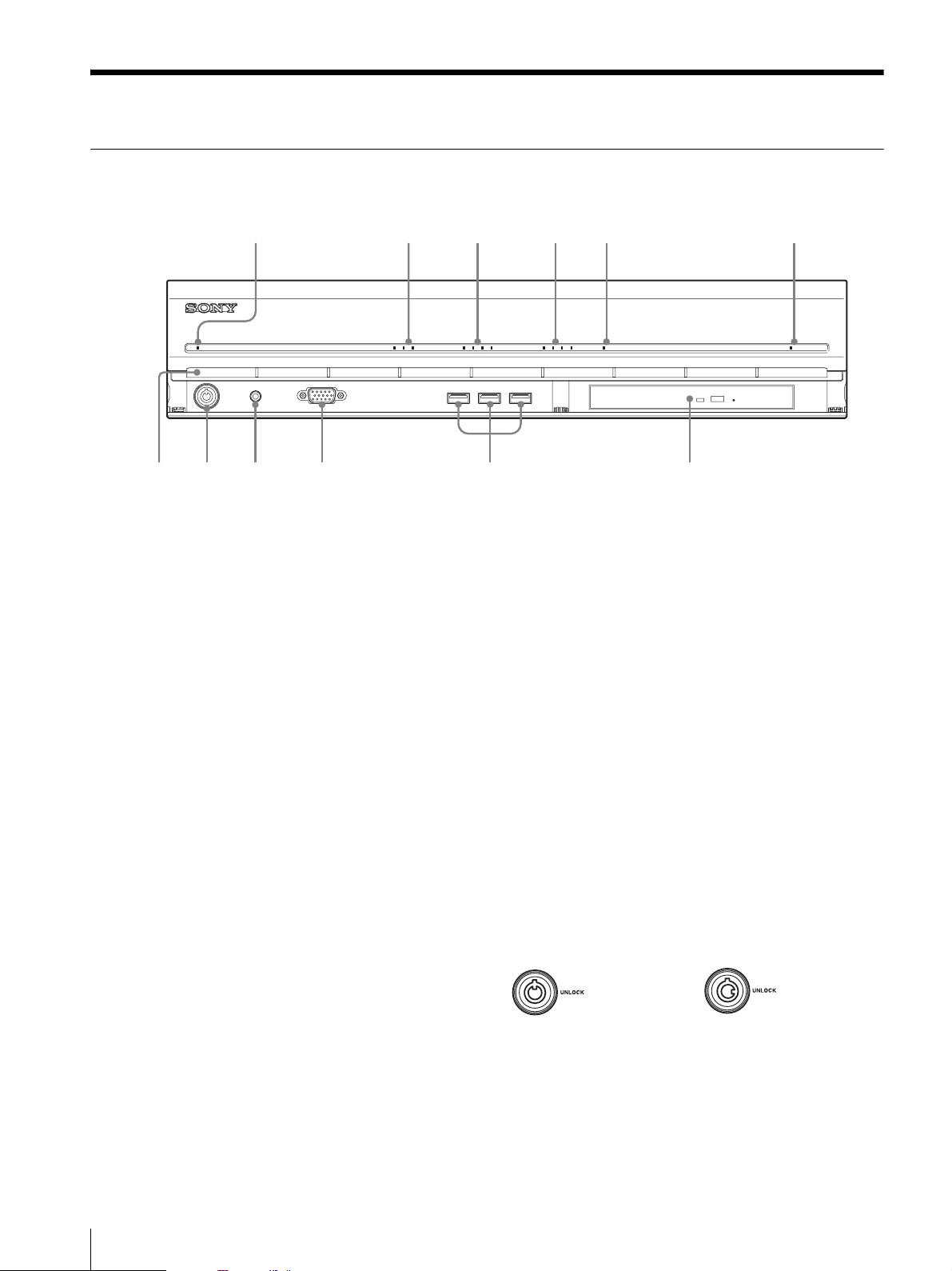
Front (When the Cover is Opened)
NSR-1200/1100/1050H
12345 6
POWER 1 2 3NETWORK 1 2 3 4HDD 1 2 3 4 ERRORSTATUS REC
708qa 9qs
A Power LED
Lights green when the unit is turned on.
Lights amber when it is on standby.
B Network LED (1 to 3)
Lights green when there is activity at the corresponding
LAN connector at the rear of the NSR.
C HDD LED
Blinks green when the internal hard disks are accessed.
Lights amber when an error occurs with a hard disk.
D Status LED (1 to 4)
Lights in sequence (1, 2, 3, 4) when the NSR starts.
When an error occurs, the corresponding status LED
lights together with the error LED, which lights or blinks
to indicate the type of error.
For details, see “STATUS LED” (page 30).
E Error LED
Lights or blinks when an error occurs.
F REC LED
Lights when recording images.
H USB connector
Use this connector to connect a USB keyboard, mouse,
or USB flash memory to the NSR.
I Monitor connector 1
Use this connector to connect a monitor.
Monitor connector 1 (and monitor connector 1 on the
rear of the unit) and HDMI monitor connector 1 on the
rear of the unit cannot be used at the same time.
J Power switch
Press this to turn on the unit. (You cannot turn off the
unit with this switch.)
K Lock
Use this in conjunction with the supplied front panel key
to lock the front bezel. When the front bezel is locked,
you cannot pull out the front bezel. Also, do not lock the
front bezel when the front bezel is pulled out. You can
distinguish the locked position from the unlocked
position by looking at the lock, as illustrated below.
The front bezel is
locked
The front bezel is
unlocked
G DVD/CD drive
Use this drive to write data from the NSR hard disks to
DVD and CD.
8
Features and Functions
L Vent ho l e s
These openings allow air to flow from the front of the
NSR to the rear.
Do not block the vent holes, allow dust to accumulate in
the inner mesh of the vent holes, or obstruct the airflow
in any way. Obstructing the airflow allows heat to build
up inside the NSR and may result in fire or damage.
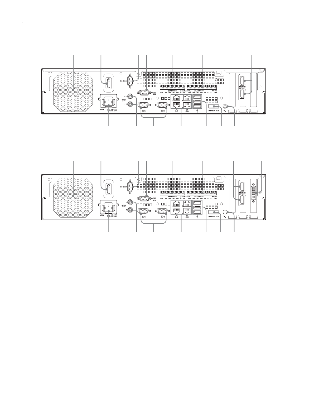
Rear
8q
q
90q
q
NSR-1200/1100
NSR-1050H
2316547
9qs 0qaqdqf
8
2316547qg
f
A Fan
Take care not to obstruct the fan grille. If the grille is
obstructed, heat may build up in the unit, leading to
damage and/or fire.
B Power switch
Press the switch in the 1 position to turn on the unit.
C RS-232C Connector
Use this connector to control analog cameras.
This connector cannot be used at the same time as the
RS-422/485 connector (four rightmost pins on F alarm
output connector).
D UPS connector (RS-232C)
Use this connector to connect the control line of the
uninterruptible power supply (UPS).
d
s
E Sensor input connector
Use this connector to connect the sensor input lines.
For connection details and wiring diagrams for sensor
inputs, see “I/O Port” (page 31).
F Alarm output connector
Use this connector to connect the alarm output lines.
For connection details and a wiring diagram for alarm
output, see “I/O Port” (page 31).
G HDMI monitor connectors (1 and 2)
Use these connectors to connect monitors that support
HDMI input.
HDMI monitor connector 1 and L monitor connector 1
(and monitor connector 1 on the front of the unit) cannot
be used at the same time, while HDMI monitor
connector 2 and L monitor connector 2 cannot be used
at the same time.
a
Features and Functions
9

H Audio input connector
Use this connector to input audio from a peripheral
audio device, such as a microphone.
Plug-In Power microphones are supported.
I Mini-SAS output connector
Use this connector to connect the mini-SAS cable used
for connecting an NSRE-S200.
The NSRE-S200 is an optional expansion storage unit.
J USB connector
Use this connector to connect a USB keyboard, mouse,
or USB flash memory to the NSR.
K LAN connectors (1 to 4)
Use these connectors to connect 10 Base-T, 100 BaseTX, or 1000 Base-T network cables.
LAN1: Network cameras
LAN2: Remote Clients
LAN3: Used for future expansion
LAN4: Used for future expansion
L Monitor connectors (1 and 2)
Use these connectors to connect a monitor.
Monitor connector 1 (and monitor connector 1 on the
front of the unit) and H HDMI monitor connector 1
cannot be used at the same time, while monitor
connector 2 and H HDMI monitor connector 2 cannot
be used at the same time.
M Audio output connectors (L and R)
Use these connectors to output audio to a peripheral
audio device.
N Power supply connector
Use this connector to connect the power cord.
O Analog camera cable input connector
Use this connector to connect analog cameras via the
analog camera input cable.
The NSR-1050H is standard equipped with this
connector, but the NSR-1200/1100 requires an NSBKA16 (optional) expansion.
Reference Data for
Installation
Current Consumption and Inrush
Current
Model AC input
NSR-1200
NSR-1100
NSR-1050H
NSRE-S200
voltage
100 V 2.66 A
220 V 1.14 A
100 V 1.84 A
220 V 0.79 A
100 V 1.75 A
220 V 0.76 A
100 V 0.79 A
220 V 0.34 A
Storage Capacity for Recorded
Data
The storage capacities for recorded data on the NSR1200/1100/1050H and optional expansion storage are as
follows.
Model Storage capacity for recorded data
NSR-1200 1,366 GB
NSR-1100 886 GB
NSR-1050H 443 GB
NSRE-S200 1,396 GB
* Data capacities are approximations based on the following
equation for 1 GB:
1,024 × 1,024 × 1,024 = 1,073,740,000 bytes
Full loading Inrush
current
13 A
10
Reference Data for Installation
Recording Duration Guide
Server Expansion
NSR-1050H
NSR-1100
NSR-1200
NSR-1200
storage
0 units 8 MPEG4
0 units 16 MPEG4
0 units 16 MPEG4
7 units 16 MPEG4
Number
of
cameras
Codec
(size)
(VGA)
(VGA)
(VGA)
(VGA)
Number
of days
10 512 kbps 10.00 fps
10 512 kbps 10.00 fps
16 512 kbps 10.00 fps
60 1,024 kbps 20.00 fps
Bitrate Frame
rate
Server Expansion
NSR-1050H
NSR-1100
NSR-1200
NSR-1200
storage
0 units 4 JPEG
0 units 4 JPEG
0 units 16 JPEG
7 units 16 JPEG
Number
of
cameras
Codec
(size)
(VGA)
(VGA)
(VGA)
(VGA)
Number
of days
Quality Frame
4 Level 5 10.00 fps
10 Level 5 8.00 fps
30 Level 5 1.00 fps
30 Level 5 9.00 fps
rate
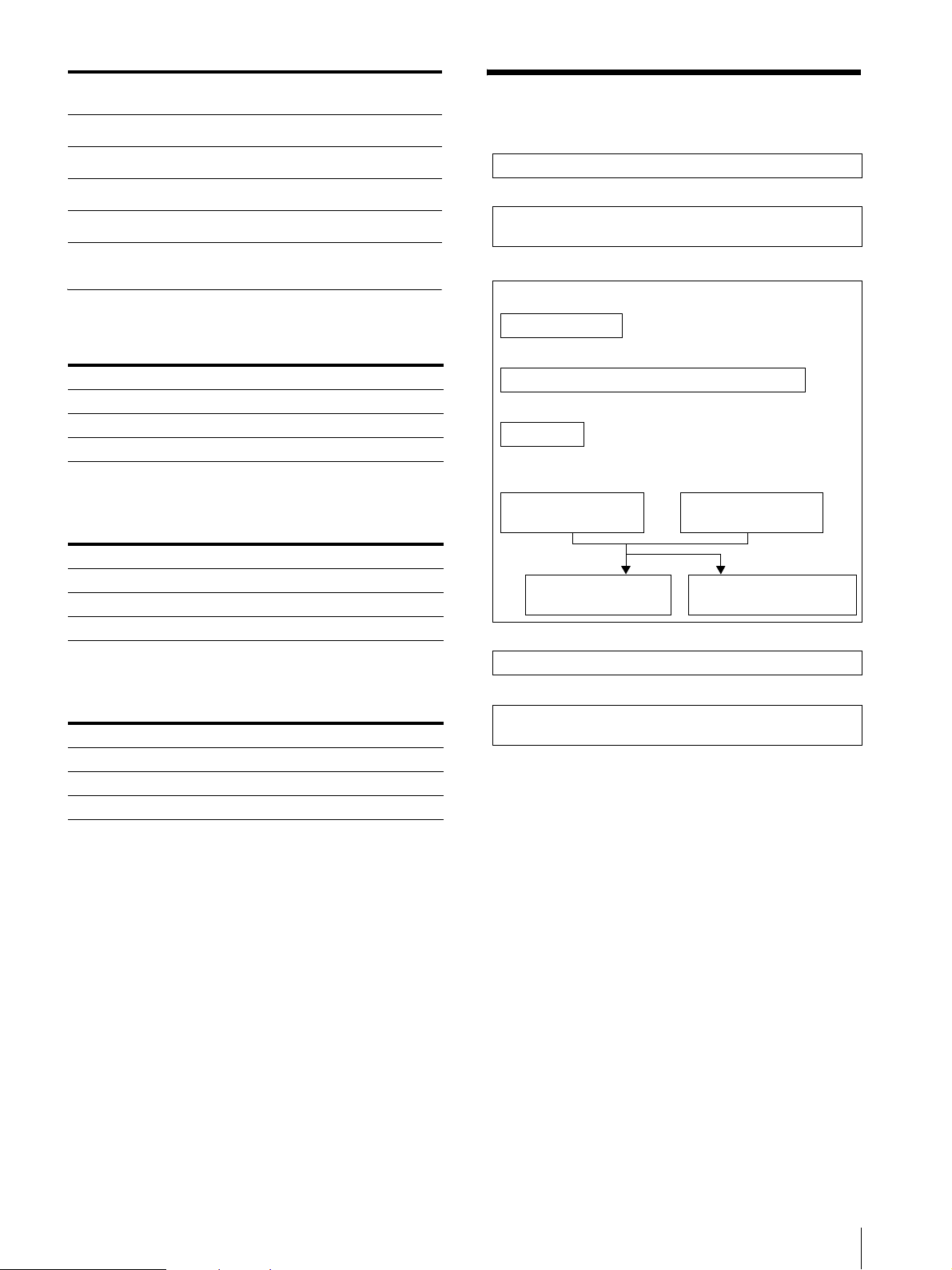
Preparation Steps
Step 1: Installation (page 12)
↓
Step 2: Connections (page 15)
Connect each device to the unit.
↓
Number of Cameras
Maximum number of cameras
Model Maximum number of cameras
NSR-1200 64
NSR-1100 32
NSR-1050H 20
Maximum number of analog cameras (included
in total number of cameras)
Model Maximum number of analog cameras
NSR-1200 16 (with optional NSBK-A16)
NSR-1100 16 (with optional NSBK-A16)
NSR-1050H 16
Maximum number of megapixel cameras
(included in total number of cameras)
Model Maximum number of cameras
NSR-1200 8
NSR-1100 4
NSR-1050H 4
Step 3: Settings (page 20)
Turn on the unit.
↓
Configure initial settings with the Setup Wizard.
↓
Log on.
↓
Perform basic configuration.
Register cameras
automatically.
Configure alarm
recording.
Select cameras to
register.
Configure scheduled
recording.
↓
Step 4: Verifying Operation (page 27)
↓
If advanced configuration is necessary
Refer the User’s Guide (PDF).
Ex.) NSR-1050H (maximum number of cameras: 20)
IP cameras : 12
IP cameras (megpixel) : 4
Analog cameras : 4
Preparation Steps
11
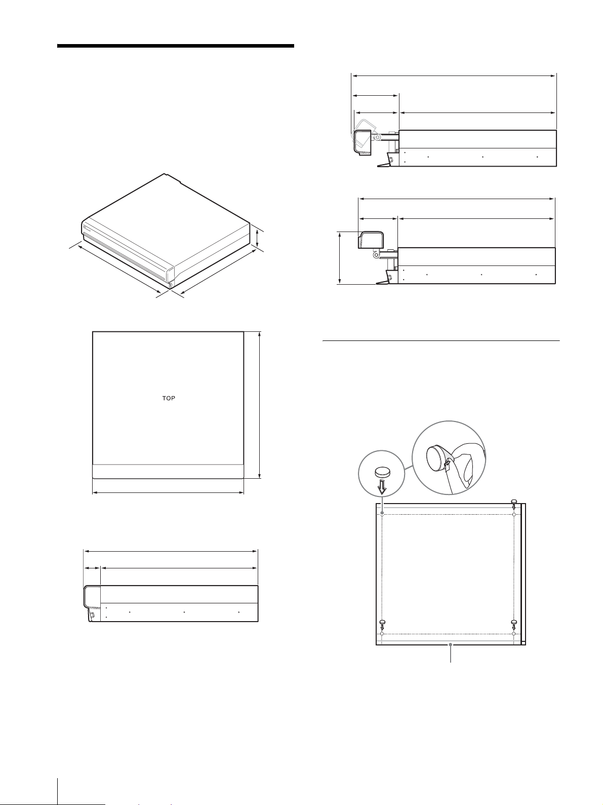
When the front bezel is opened
Step 1: Installation
Before setting up, be sure that the location for
installation provides sufficient space and strength to
support the unit.
The NSR-1200 weighs approx. 13.5 kg (29.8 lb.), the
NSR-1100 weighs approx. 12 kg (26.7 lb.), and the
NSR-1050H weighs approx. 11.5 kg (25.4 lb.). The
dimensions for the unit are as follows.
3.4 in.
(87 mm)
Top
16.9 in.
(430 mm)
16.4 in.
(417 mm)
19.4 in. (494 mm)
4.6 in.
(117 mm)
4.2 in.
(106 mm)
4.0 in.
(102 mm)
4.8 in.
(123 mm)
14.8 in. (377 mm)
18.9 in. (479 mm)
14.8 in. (377 mm)
You can install the unit on a rack using the optional rack
mounting kit.
Installation Without a Rack
16.9 in. (430 mm)
When the front bezel is closed
16.4 in. (417 mm)
14.8 in. (377 mm)1.6 in. (40 mm)
Attach the provided rubber feet to the recorder.
Place the recorder upright so that the bottom surface is
visible. Then affix the adhesive surfaces of the rubber
feet on the bottom of the recorder as illustrated below.
16.4 in. (417 mm)
Rubber
foot
Remove
the film
12
Bottom of the unit
Step 1: Installation
Rack Mount Installation
Install the NSR in a rack using the optional rack
mounting kit (sold separately).
Warning
• Do not use a rack mounting kit other than the optional
mounting kit (sold separately) for the NSR, as doing
so is dangerous and may result in fire, shock, or injury.
• If you mount the NSR in a rack, make sure not to place
heavy object on it.
• Before mounting the NSR in a rack, we recommend
that you mark its intended position in the rack with a
felt-tip pen. Mounting the NSR in the rack other than
horizontally could result in malfunctions.
• To order a rack mounting kit, contact your retailer.
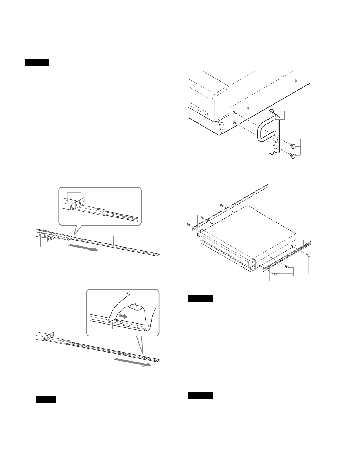
Pulling Out the Inner Rails
Pull out the inner rails from the rail assemblies.
1
Pull out the inner rail from one of the rail
assemblies as far as it can go.
Back of rail assembly
Preparing the NSR
Use the supplied fasteners and screws to install the inner
rail on the NSR.
1
Use the supplied flat head screws to attach the
mounting ears to the front of the side panel.
Mounting ear
Flat head
screws
2
Use the remaining supplied round head screws to
install the rails to the NSR, as illustrated.
Inner rail
Rail assembly
2
Turn the rail assembly over. As you pull the green
tab outward to release the lock, pull the inner rail all
the way out.
Green tab
3
Repeat the same procedure with the other rail
assembly to pull out its inner rail.
Green tab
Green tab
Caution
Using screws other than the supplied screws may
damage the unit. Be sure to use the supplied screws
to install the rails.
Round head
screws
Preparing the Rack
Install the rails on the rack.
1
Determine where you want to install the rails on the
rack.
We recommend marking this position with a
marker or felt tip pen.
Rail
Note
The inner rail will be installed on the NSR, while
the rail assembly will be installed on the rack.
Caution
Rails installed at different heights could result in
NSR malfunctions.
Step 1: Installation
13
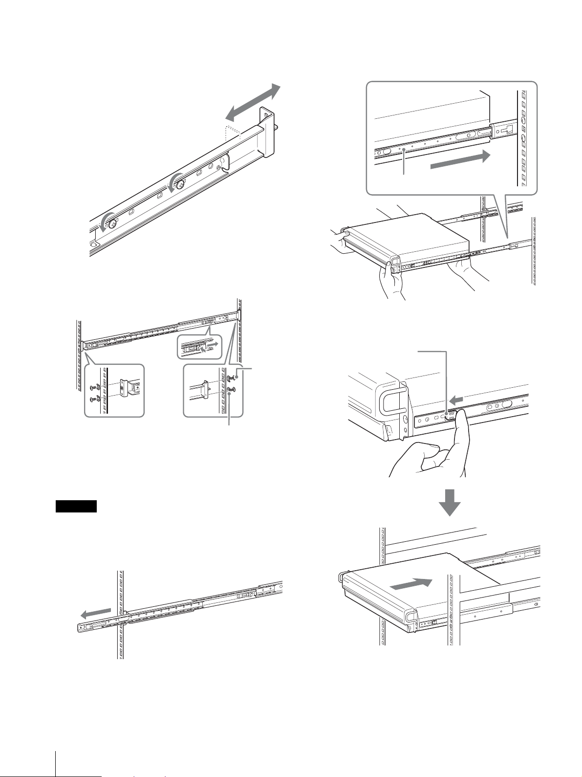
2
Install the rails on the rack.
(1) Adjust the length of the rails to match the length
of your rack.
(2) Use the supplied truss screws and washers to
secure both ends of the rails to the rack.
2
Lift the NSR, fit the inner rails into the slide rail
grooves (white), and then slide the assembly until it
stops.
Inner rail
3
As you pull the green tab inward to release the lock,
slide the NSR as far as it can go.
Truss
screws
Washers
Mounting the NSR on the Rack
Insert the NSR into the rack, and then secure it.
Caution
At least two people are needed in order to handle the unit
to prevent personal injury.
1
Pull the sliding rails from the rail assemblies.
Green tab
14
Step 1: Installation
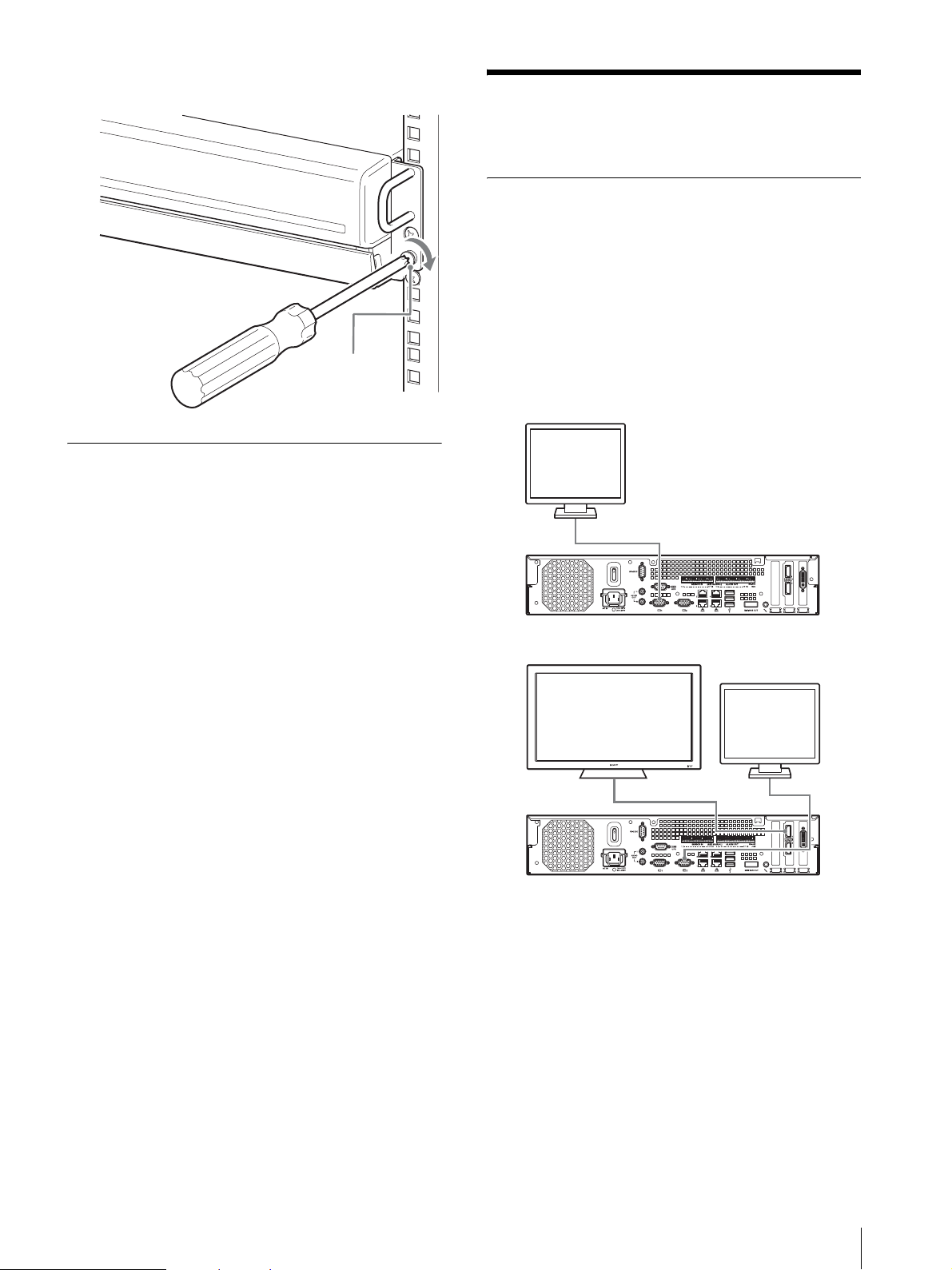
4
Use the supplied round head screws to secure the
NSR to the rack.
Round head
screw
Installing Optional Accessories
For details on installing an NSRE-S200, refer to the
operating instructions supplied with the NSRE-S200.
For details on installing an NSBK-A16, contact your
Sony dealer.
Step 2: Connections
Connect each device to the unit.
Connecting a Monitor
When connecting one monitor, connect it to analog RGB
monitor connector 1 or HDMI monitor connector 1.
When connecting a second monitor, connect it to analog
RGB monitor connector 2 or HDMI monitor connector
2.
For details, see “Monitor Connection Examples”
(page 28).
Example) When connecting to rear monitor connectors
Monitor 1
Monitor connector 1
Monitor 1
Monitor 2
Monitor connector 2Monitor connector 1
Step 2: Connections
15
Recommended connector use while operating
the unit
Monitor Connectors to use
Analog
RGB
monitor
connector
2
One
monitor
Two
monitors
HDMI
monitor
Analog
RGB
monitor
HDMI
monitor × 2
Analog
RGB
monitor × 2
HDMI
monitor and
Analog
RGB
monitor
HDMI
monitor
connector
1
HDMI
monitor
connector
2
Analog
RGB
monitor
connector
1
a –––
––a –
aa ––
––aa
a ––a
– aa –
Notes
• There are three monitor connectors labeled “1”
(analog RGB ×2; HDMI ×1) and two monitor
connectors labeled “2” (analog RGB ×1; HDMI ×1),
but only one of each (1 and 2) can be used at any one
time.
• Do not turn on the unit while monitors are connected
to analog RGB monitor connector 1 on both the front
and rear of the unit.
• When operating the unit with only one analog RGB
monitor, do not connect the monitor to analog RGB
monitor connector 1 on the front of the unit while the
unit is turned on.
• When connecting two analog RGB monitors, do not
use the HDMI monitor connectors.
• When using HDMI monitors, be sure to connect the
HDMI monitor and turn it on before turning on the
unit.
• Observe the following restrictions when using analog
RGB monitor connector 1 on the front of the unit.
- Do not connect monitors to HDMI monitor
connector 1.
- Do not connect to analog RGB monitor connector 1
on the front and rear of the unit at the same time
while the unit is turned on. The monitors will not be
recognized if both connectors are used.
• When monitors are connected via a monitor switch,
images may not always display. We recommend
connecting monitors directly to the unit.
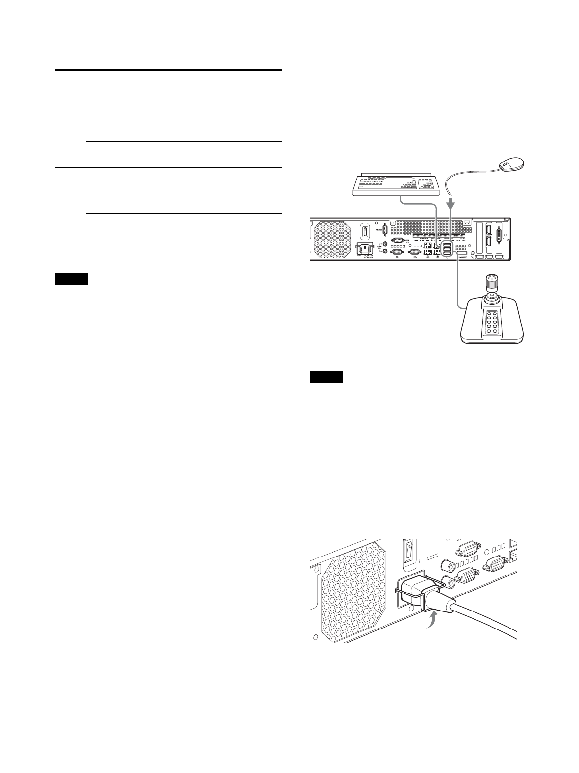
Connecting the Keyboard, Mouse
and Remote Control Unit
Connect the devices to the USB connectors on the front
and rear of the unit.
Example) When connecting to the USB connectors on
the rear
Mouse
Keyboard
Remort control
Notes
• This unit supports IP Desktop USB controllers from
CH Products. Other remote controllers are not
supported.
• When using USB devices, be sure to read “Precautions
for using USB devices” (page 4) in the “Usage
Precautions” section beforehand.
Connecting the Power Cord
Connect the power cord to the power supply connector.
Attach the safety clip to prevent the power cord from
disconnecting.
16
Step 2: Connections
Caution
• Before installing, carefully read “Important
Information About Safety” (page 3). When using the
unit in combination with multiple NSR units or an
optional NSRE-S200, make sure that the power
supply is sufficient.
• For details on the current consumption and inrush
current for the NSR-1200/1100/1050H and NSRES200, see “Reference Data for Installation” (page 10).
included in the install archive for RealShot Manager
Advanced client software.
• When using RealShot Manager Advanced as a remote
controller for the NSR, select [Client] during
installation of RealShot Manager Advanced.
• When connecting to the user area network, use LAN
connector 2.
• For details on NSR settings when using the RealShot
Manager Advanced client software, see
“Configurations for Using RealShot Manager
Advanced Client Software” (page 26).
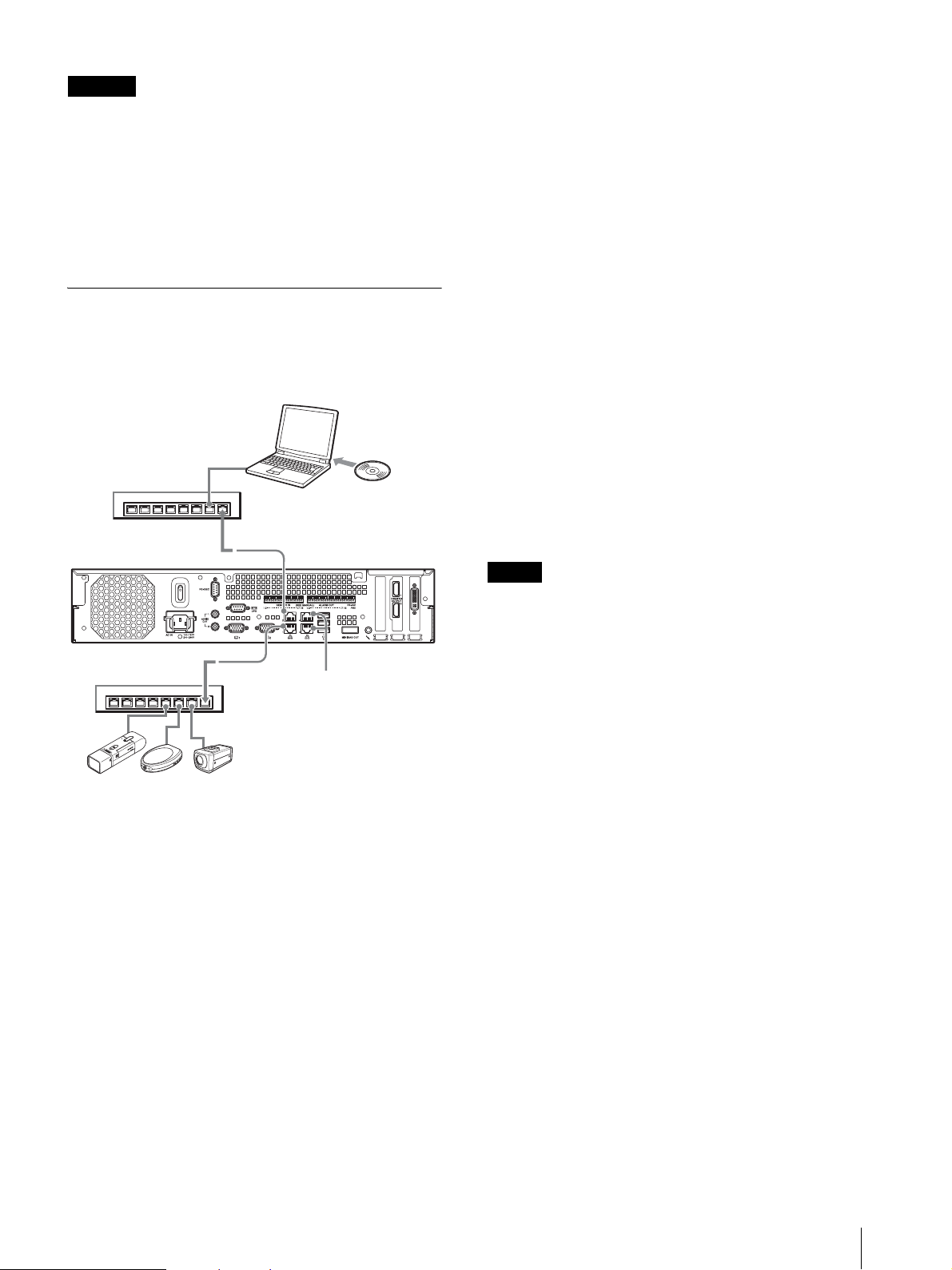
Connecting to a Network
Connect to the network as follows.
Remote client
Connect LAN connector to the same network as the
Windows PC being used as the remote client.
Network switch
LAN connecter 1
Network switch
Windows PC
LAN connecter 2
LAN connectors 3 and 4
(used for future expansion)
RealShot
Manager
Advanced
Client software
LAN connectors 3 and 4 (used for future
expansion)
As LAN connectors 3 and 4 are channel bonded for
network redundancy, only one IP address can be
assigned for both connectors. Be sure to connect LAN
connectors 3 and 4 to the same network switch.
When both LAN connectors 3 and 4 are connected to the
network switch, data communication is enabled for only
one of the two the connectors.
The active network is determined at startup, and you
cannot specify which network to use. If the active
network fails and data communication is disabled, data
communication will resume using the other network.
Notes
• The default IP addresses for this unit are as follows.
- LAN connector 1: 192.168.0.1
- LAN connector 2: 192.168.1.1
- LAN connector 3: 192.168.2.1
- LAN connector 4: 192.168.2.1
• If you want to change the default IP addresses, refer to
the User’s Guide (PDF).
Network cameras
Connect LAN connector 1 to
the same network as the
network cameras.
Connections to remote clients
When a remote client is necessary, you can use the
RealShot Manager Advanced client software supplied
with this unit.
• Use the version of RealShot Manager Advanced
supplied with this unit. For details on how to
download the installer for RealShot Manager
Advanced, see “Downloading Files Stored on the
NSR” (page 6). You can also download the installer
for the latest version of RealShot Manager Advanced
from the following URL.
http://www.sony.co.jp/net/Products/RSMAd/license_form.html
For details on installation and connecting to the NSR,
refer to the RealShot Manager Advanced Installation
Guide (PDF).
• RealShot Manager Advanced client software operates
on Windows computers. For details on recommended
system specifications, refer to the release notes
Step 2: Connections
17
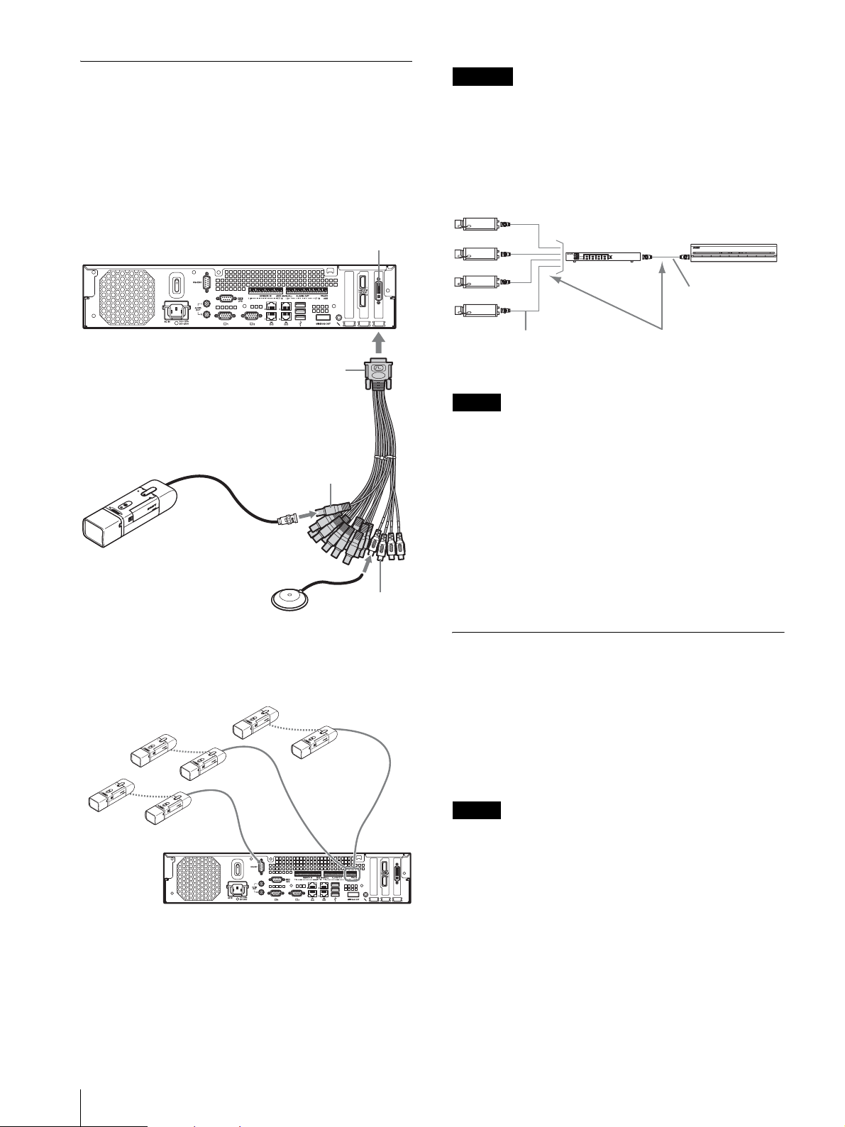
Connecting an Analog Camera
Caution
Connect the analog camera using the supplied analog
camera input cable.
To control pan, tilt, and zoom operations, connect a
camera control cable to the RS-232C connector or the
RS-422/485 connector (four rightmost pins on the alarm
output connector). (Only one of these connectors (RS232C, RS-422, RS-485) can be used at any one time.)
Analog camera cable input connector
Analog camera input cable
Video input
connector (black)
Analog camera
Audio input
Audio device
connector
(white)
Connection Example
Analog cameras PTZ
(RS-485 control)
Analog cameras PTZ
(RS-422 control)
When using cameras and power supply units that
superimpose DC voltage on the video coaxial cable, pay
close attention to the coaxial cable wiring. If the camera
cable on which DC voltage is superimposed is
connected to the NSR, malfunctions may occur.
Analog cameras
Coaxial cable on
which DC voltage
is superimposed
Notes
Power supply unit
Be careful not to connect the
coaxial cable for the analog
cameras to the NSR unit.
VIDEO
OUT
NSR
POWER 123NETWORK 12 34HDD 1 2 34 ERRORSTATUS REC
Coaxial cable
• The NSR-1050H is standard equipped with the analog
camera cable input connector, but the NSR-1200/1100
requires an NSBK-A16 (optional) expansion.
• When using pan, tilt, and zoom operations, you must
configure a unique control number for each analog
camera using the dip switches or menus. For details on
configuring control numbers, refer to the operating
instructions for the analog camera.
• For details on the pin assignment for the RS-422/485
connector, see “Pin Assignment of I/O Port”
(page 31).
Connecting an NSRE-S200
Use the mini-SAS cable supplied with the optional
NSRE-S200 to connect the NSR-1200/1100/1050H to
the NSRE-S200 as follows.
You can connect up to seven NSRE-S200 units to the
NSR-1200/1100/1050H.
For details on connection configurations, see “NSRES200 Connection Example” (page 29).
Analog cameras PTZ
(RS-232 control)
18
Step 2: Connections
Note
Be sure to connect the NSR-1200/1100/1050H and the
NSRE-S200 before turning on the power.
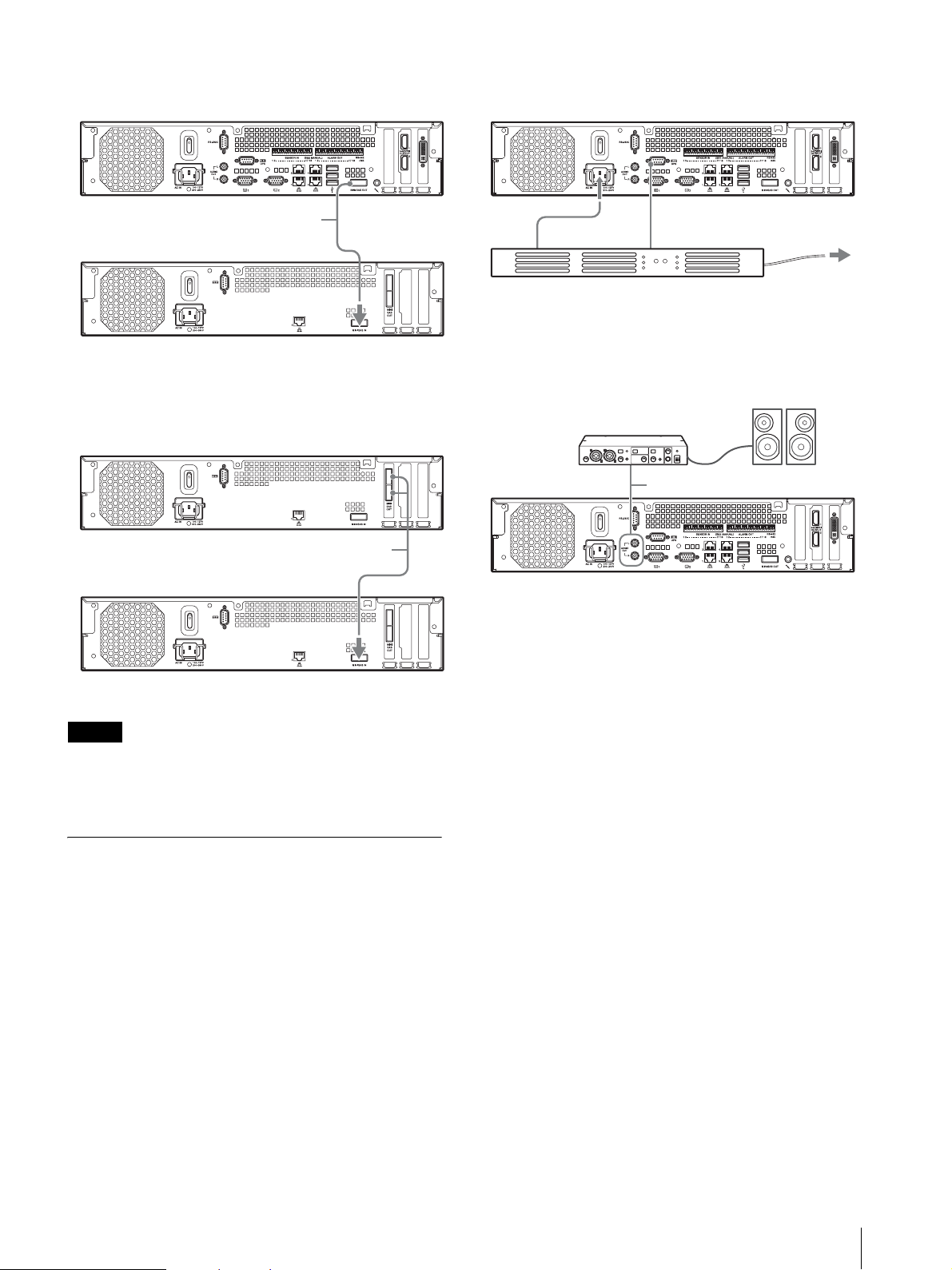
Connecting the NSR-1200/1100/1050H to the
NSRE-S200
3
Connect the NSR to the UPS with the dedicated serial
cable to the serial connector on the rear of the NSR.
Mini-SAS cable
Connecting two NSRE-S200 units
Mini-SAS cable
Mini-SAS output
connector
Mini-SAS input
connector
Mini-SAS output
connector
Power cord
Serial cable
To Power source
UPS
Connecting an Audio Output Device
Connect the audio output device to the audio output
connectors (L and R).
Audio cable (L and R)
Mini-SAS input
connector
Note
The upper and lower mini-SAS output connectors on the
NSRE-S200 are identical in function.
Connecting Other Devices
Connecting Sensor Inputs and Alarm
Outputs
Connect the wires to the sensor input connector and the
alarm output connector.
For details, see “I/O Port” (page 31).
Connecting an Uninterruptible Power
Supply (UPS)
1
Connect the UPS to the power outlet.
2
Connect the NSR to the UPS with the supplied
power cord.
Step 2: Connections
19
Step 3: Settings
This section provides information on how to turn on the
unit, and general explanations on how to register
cameras and other devices.
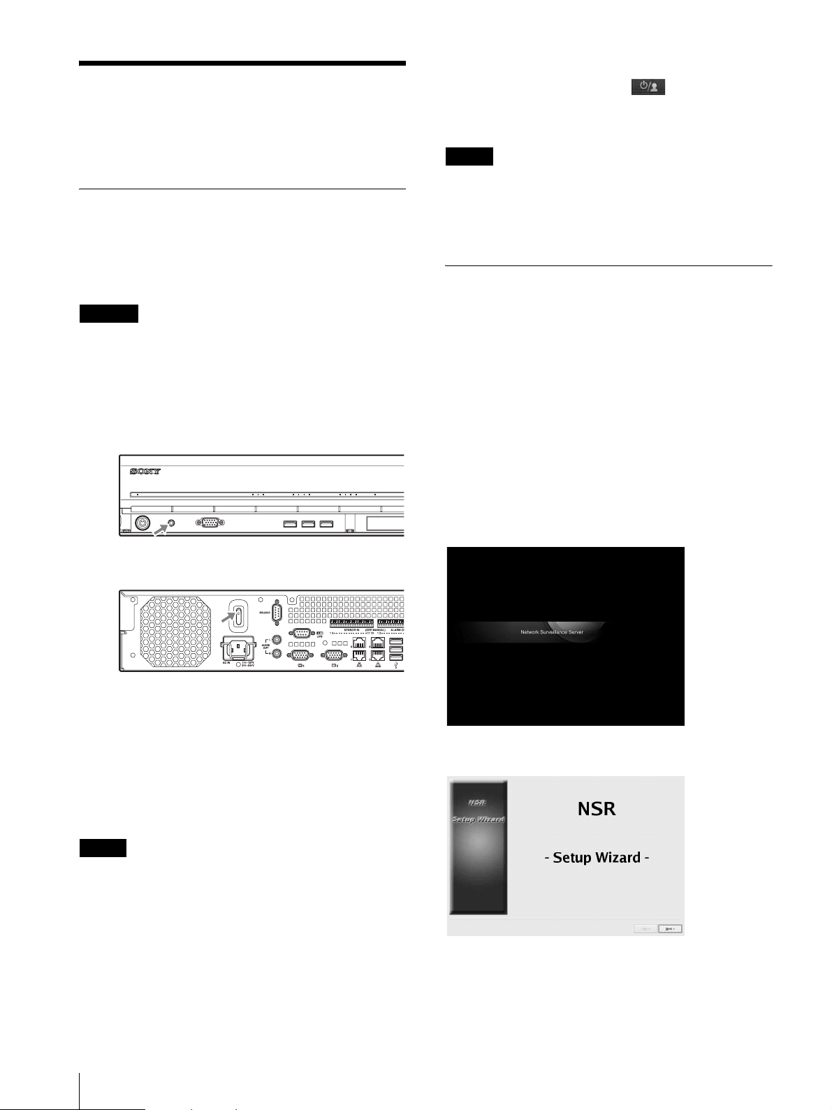
Turning On the Unit
When you press the power switch on the front or rear of
the unit, the unit will turn on. When an optional NSRES200 is connected, wait until the NSRE-S200 has turned
on before turning on this unit.
To turn off the unit
After logging on to NSR, click at the top of the
“Main” screen, and select [Shutdown] from the menu
that appears.
Note
Normally, the unit turns off after a few minutes. If the
unit does not turn off after a few minutes, force
shutdown by pressing the power switch on the rear panel
of the unit in the 1 position for at least 5 seconds.
Configuring Initial Settings with
Caution
Take the inrush current into consideration when
configuring power connections for systems that include
multiple NSR units or an NSRE-S200 unit. For details
on the inrush current, see “Reference Data for
Installation” (page 10).
Front power switch
POWER 1 2 3NETWORK 1 2 3 4HDD 1 2 3 4 ERRORSTATUS
Rear power switch
Setup Wizard
This section explains the general flow of the Setup
Wizard. For further details on settings, refer to
“Changing System Settings” in the User’s Guide (PDF).
The Setup Wizard starts automatically when you turn on
the unit for the first time. You can configure the same
settings afterward by accessing the logon screen, the
Administration Menu, and then the Setup Menu.
For details, refer to “To access the Setup Menu from the
logon screen” (page 24).
When you turn on the unit, the Setup Wizard starts after
the following screen appears.
The power LED on the front panel is lit green when the
unit is turned on.
When you turn on the unit for the first time, the Setup
Wizard starts automatically.
Continue to the following section, “Configuring Initial
Settings with Setup Wizard.”
Notes
• The fan noise may be loud for about 2 seconds after
turning on the unit. This is not a malfunction.
• If the unit was shut down through system operations,
press the power button on the front panel or the power
switch on the rear panel to turn on the unit.
• If a forced shutdown was performed previously, the
unit may take longer to start up.
20
Step 3: Settings
↓
Click [Next].
↓
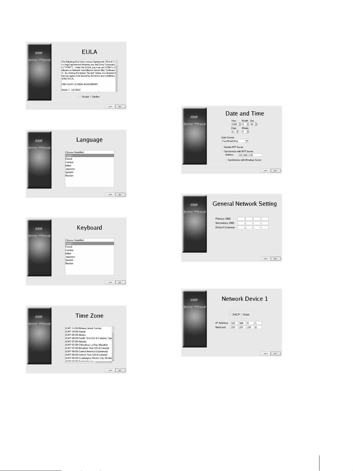
Read the user license agreement carefully, click
[Accept], and then click [Next].
↓
Select a display language, and click [Next].
Set the date and time, and click [Next].
• When you select the [Enable NTP Server] check box,
the unit acts as the NTP server for date and time
synchronization.
• When you select the [Synchronize with NTP Server]
check box, you can synchronize the date and time with
a different NTP server.
• If the date and time cannot be synchronized with the
Windows server as the NTP server, you can select the
[Synchronize with Windows Server] check box to
force synchronization with the Windows NTP server.
↓
Set the IP address for each server, and click [Next].
↓
Select a language for the keyboard, and click [Next].
↓
Select a time zone, and click [Next].
↓
Set the IP address for LAN connector 1, and click
[Next].
↓
↓
Step 3: Settings
21
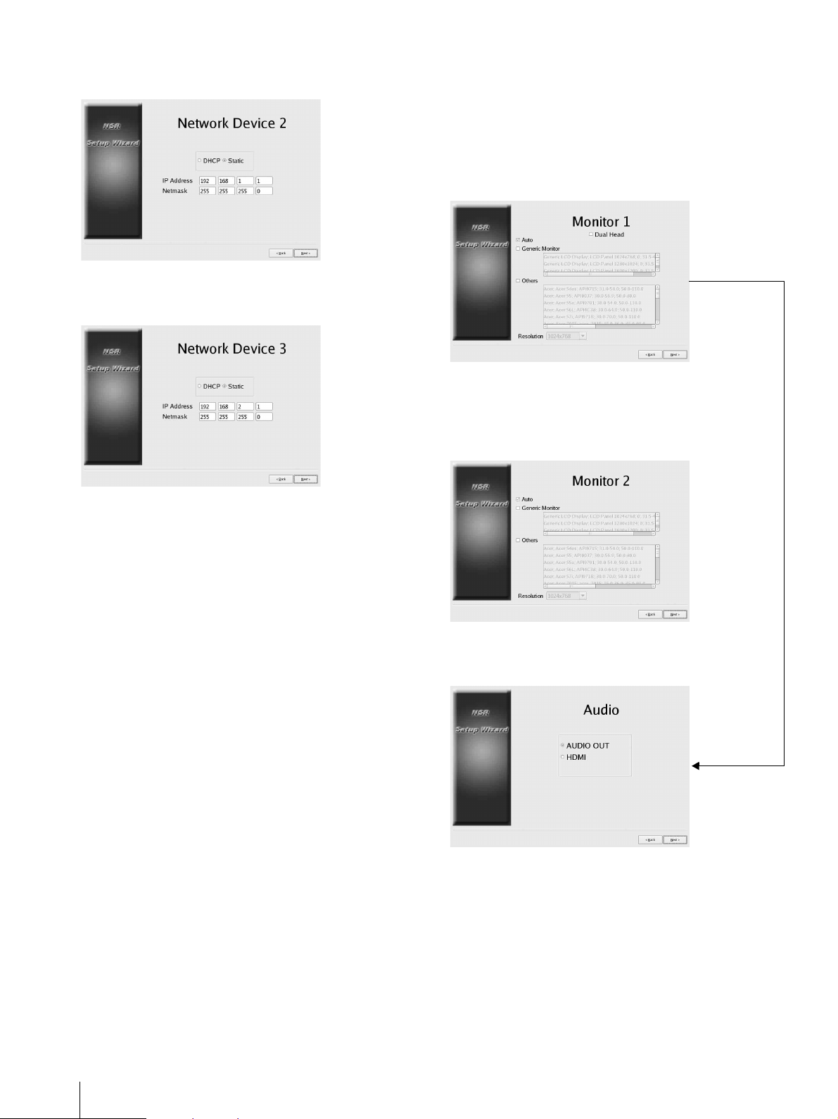
Set the IP address for LAN connector 2, and click
[Next].
↓
Set the IP address for LAN connector 3, and click
[Next].
Configure settings for monitor 1, and click [Next].
• If you select [Auto], the type of monitor connected
and its resolution are detected and configured
automatically.
For details on supported resolutions, see “System
Requirements” (page 5).
• When connecting two monitors to the unit, select the
[Dual Head] check box.
↓
If connecting a second monitor, configure settings for
monitor 2.
After configuring settings for the second monitor, restart
the unit while the second monitor is connected
↓
↓
Select the audio output connector to use, and click
[Next].
↓
22
Step 3: Settings
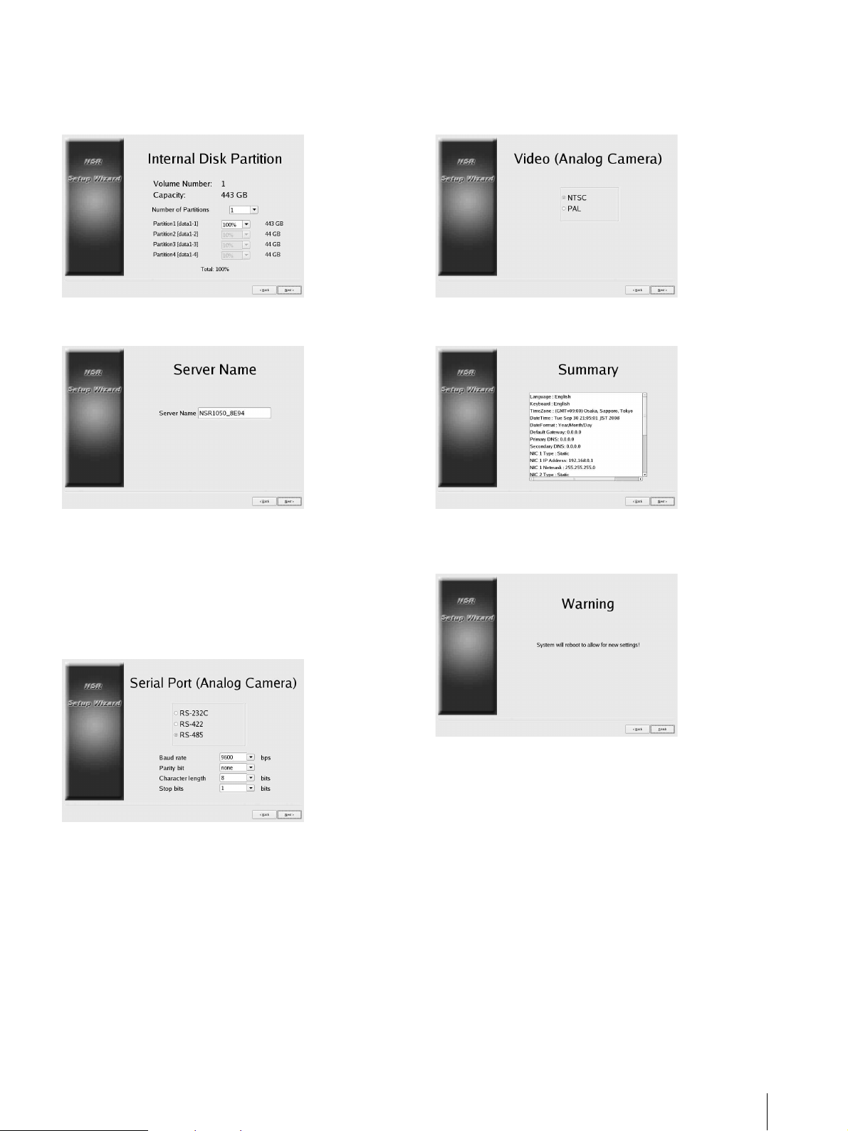
Configure partitions for the internal hard disk drive, and
click [Next].
Specify the number of partitions, and select the
percentage of total the capacity to assign each partition.
Select the video format for the analog cameras to be
connected, and click [Next].
(This screen only appears when an NSR-1050H or
NSBK-A16 (optional) is connected.)
↓
Set the server name, and click [Next].
↓
Configure analog camera connection settings, and click
[Next].
Select the serial connector standard to which the camera
you want to control will be connected, and configure
settings such as baud rate and parity bits.
(This screen only appears when an NSR-1050H or
NSBK-A16 (optional) is connected.)
↓
Verify configurations, and click [Next].
↓
Click [Finish] when the restart confirmation message
appears.
↓
The unit restarts.
↓
The logon screen appears.
Continue to the following section, “Logging On.”
↓
Step 3: Settings
23
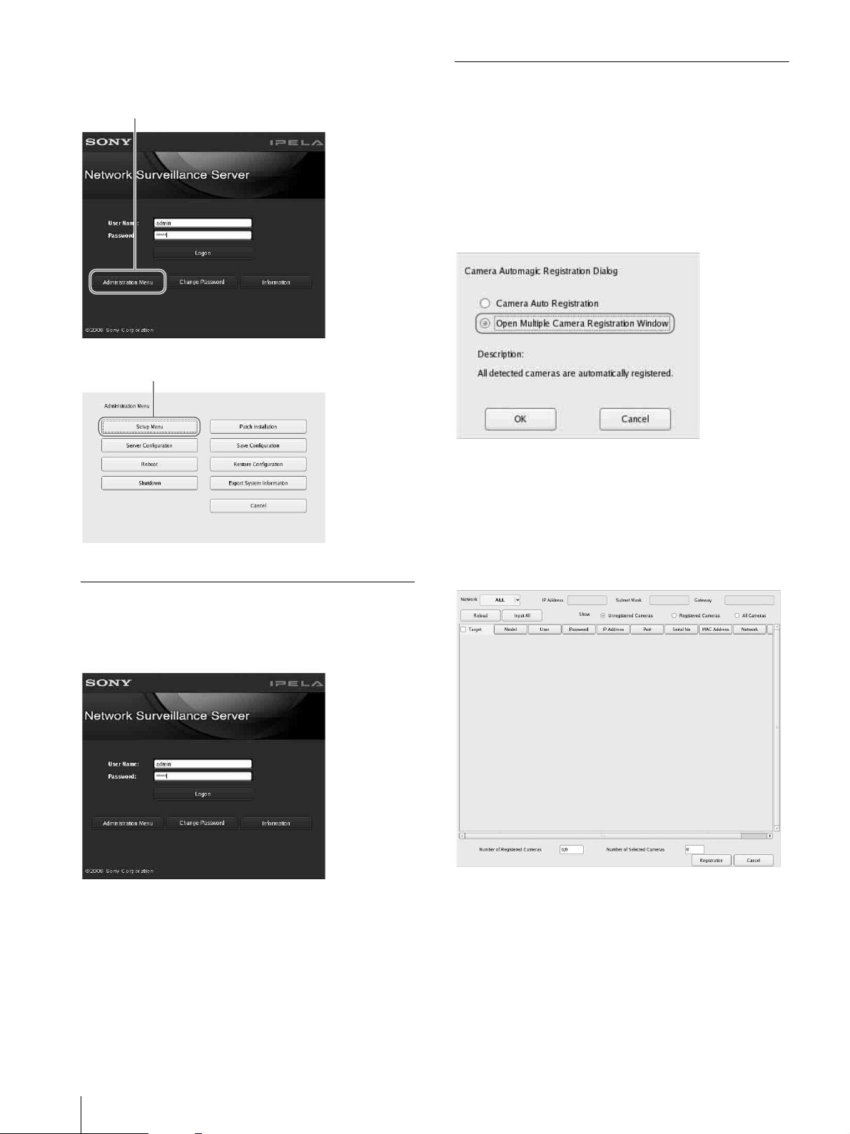
To access the Setup Menu from the logon
1
2
screen
Click [Administration Menu].
↓
Click [Setup Menu].
Logging On
Performing Basic Configuration
This section describes how to register and configure
alarm recording for devices that are automatically
detected. For details on how to register all automatically
detected devices at once, refer to the First Step Guide
(separate document).
To register a camera
Select [Open multiple camera registration window], and
click [OK].
↓
Devices on the same network segment are automatically
detected.
↓
Select the check boxes for the cameras you want to
register, and click [Register].
For further details on settings, refer to “Registering
Devices” in the User’s Guide (PDF).
Enter the user name and password, and click [Logon].
Default user name: admin
Default password: admin
When logon is successful, the Automatic Camera
Registration dialog appears.
Continue to the following section, “Performing Basic
Configuration.”
↓
24
Step 3: Settings
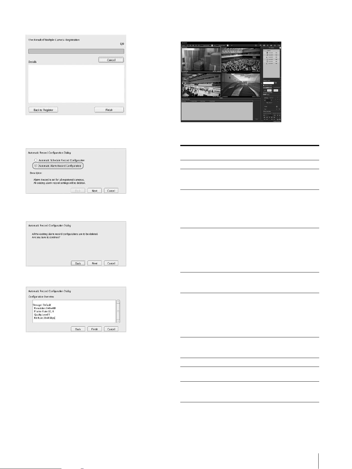
The cameras are registered.
↓
To configure alarm recording
Select [Automatic Alarm Record], and click [Next].
↓
A confirmation screen appears.
Click [Next}.
↓
Verify configurations, and click [Finish].
↓
Alarm recording starts.
When configuration is complete, the “Main” screen
appears.
After performing basic configuration, the values for
each setting will be as follows.
Setting Scheduled
recording
Image size Maximum image size supported by the camera.
Codec Codec that supports the maximum image
Frame rate JPEG:
Quality 50%
Bitrate Depends on storage
Recording
trigger
Data storage
location
Audio Disabled Disabled
Data overwrite Not changed from
Cleanup Deletes data that
size.(If supported by both JPEG and MPEG4,
MPEG4 is selected.)
Depends on storage
duration for
recorded data.
MPEG4:
Depends on bitrate.
Level 3 (cameras
with 5 level
settings)
Level 5 (cameras
with 10 level
settings)
duration for recorded
data.
– VMD (Camera)
Not changed from
existing
configuration.
existing configuration.
exceeds storage
duration.
1)
Alarm recording
JPEG: 10 fps
MPEG4: 10 fps
80%
Level 5 (cameras
with 5 level
settings)
Level 8 (cameras
with 10 level
settings)
MPEG4: 1.5 Mbps
VMD (Recorder)
JPEG: Standard
mode
MPEG4: High-
performance
mode
Not changed from
existing
configuration.
Not changed from
existing configuration.
Not changed from
existing configuration.
1)
1) If the user has not configured storage location settings for
the camera, the capacity on the first partition of the unit’s
internal hard disk is used to calculate other settings. If the
user has configured storage location settings, the capacities
for each of the locations are used to calculate other settings.
Step 3: Settings
25
Caution
1 23
21
Note
• If schedule recording and alarm recording settings
already exist when you execute “automatic record,”
the automatic configurations replace the previous
settings.
• If the camera storage locations are deliberately
changed, you can perform basic configuration again to
recalculate the other settings. The settings will not be
recalculated automatically.
Settings that Require Individual
Configuration
Further configuration is required in the following cases.
Storage location settings
Under basic configuration settings, data is stored on the
first partition of the unit’s internal hard disk.
For details on recording data to an optional NSRE-S200
unit or to other partitions, refer to the User’s Guide
(PDF).
When constructing systems that include
multiple NSR units or RealShot Manager
Advanced servers
When configuring multiple servers, individual
configuration is required. For details, refer to the User’s
Guide (PDF).
To configure these settings, you must configure the
transmission mode in the “Serial Port” settings of the
Setup Wizard beforehand.
Audio settings for cameras
Under basic configuration settings, audio is disabled.
For details on enabling audio, refer to the User’s Guide
(PDF).
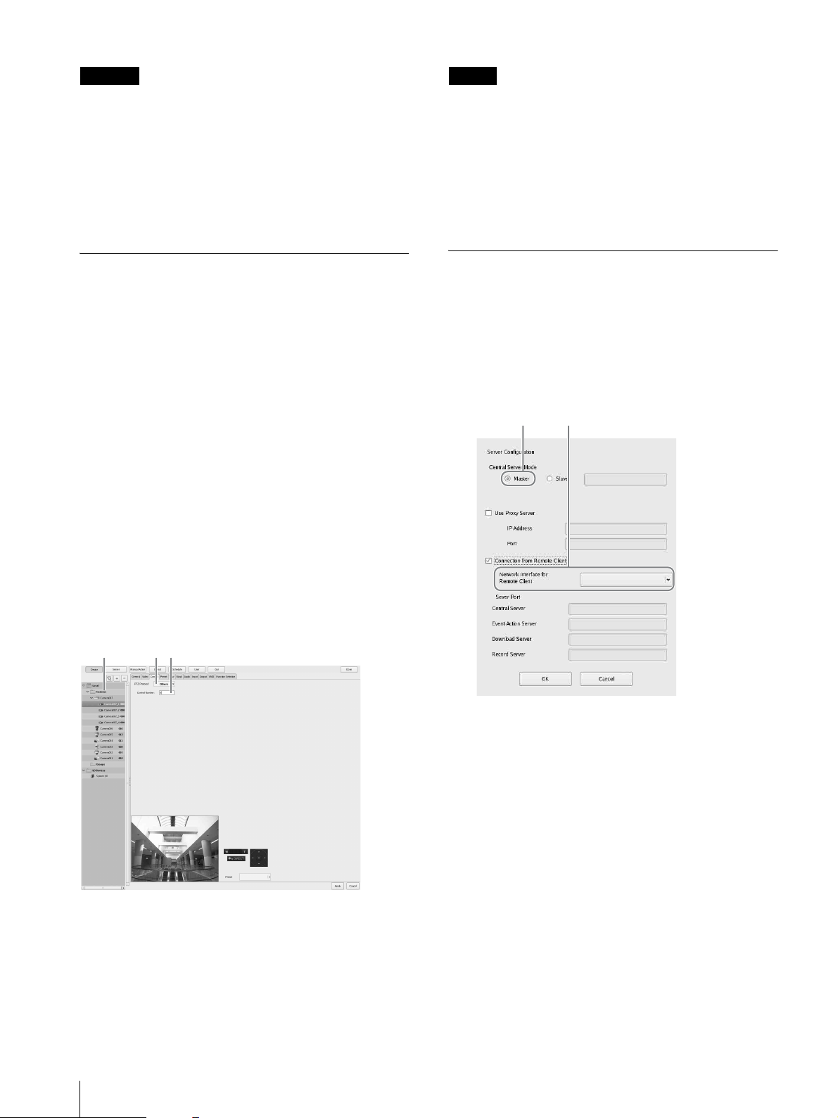
Configurations for Using RealShot
Manager Advanced Client Software
Configure the following settings on the NSR unit that
will act as the master server. For details on the settings,
refer to the User’s Guide (PDF).
1
Configure the following settings in the Server
Configuration screen of the Administration Menu.
Pan, tilt, and zoom settings for analog cameras
Configure pan, tilt, and zoom settings for analog
cameras as follows from the [Control] tab of Device
Configuration.
1 Select the analog camera.
2 Select a protocol based on the analog camera’s
3 Enter the control number configured on the selected
1 Select [Master] under [Central Server Mode].
2 Select the network interface for connection in
[Network Interface for Remote Client
Connection] under [Connect from Remote
Client].
settings.
analog camera.
26
Step 3: Settings
2
1
Create a user in the master server.
Click (add) in the User Configuration screen,
and create a user.
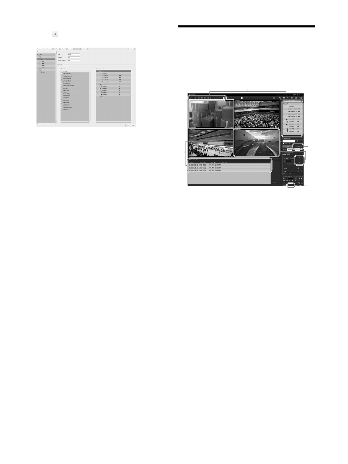
Step 4: Verifying
Operation
After basic configurations are finished, make sure that
camera images are displayed in the “Main” screen and
verify other such operations.
5
3
1 Change the layout and display images from
registered cameras.
Drag and drop a camera from the Cameras pane to
a monitor frame to display images from that
camera.
2 Click a monitor frame to activate it (light blue
frame), and control pan, tilt, and zoom from the
[Control] tab of the Camera Control pane.
3 Confirm alarm occurrences when objects pass in
front of the camera.
When alarm recording has been configured through
basic configuration, a red frame surrounds the
monitor frame, and a record of each alarm is
displayed in the Alarm History at the bottom of the
screen.
4 Refer to the Monitoring Window Operations Guide
(separate document) for details on operating each
function.
5 Click [PLAYBACK] to play back recordings.
When you click [PLAYBACK], images from a
previously configured time will be played back
(quick playback).
When you enter a date and time and click [GO],
recorded images will be played back.
6 Click the [ERROR] lamp at the bottom right of the
screen to confirm whether errors have occurred.
As the System Log appears when you click the
[ERROR] lamp, you can confirm whether problems
have occurred by viewing the log.
2
6
For details on “Main” screen operations, refer to the
Monitoring Window Operations Guide (separate
document) or the User’s Guide (PDF).
Step 4: Verifying Operation
27
Caution
When you connect a USB device to the unit, the
[ERROR] lamp at the bottom right of the “Main” screen
may light. This indicates that the unit may not support
the USB device. For details see “Usage Precautions”
(page 3) or “An external device connected to a USB
connector does not work.” (page 33) in the
“Troubleshooting” section.
Connection Examples
Monitor Connection Examples
This unit supports several combinations of monitor
connection. Refer to the following connection examples.
Note
When Using RealShot Manager
Advanced as a Remote Client
Perform the following to confirm operations.
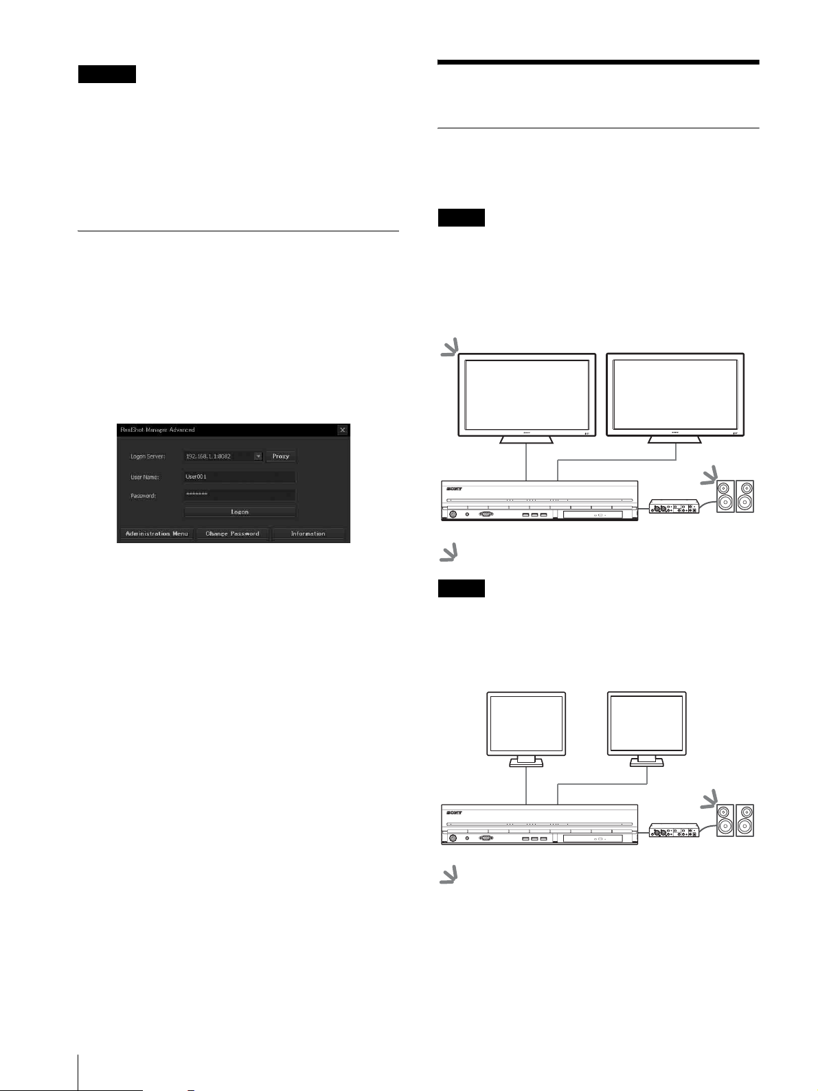
1
Log on to RealShot Manager Advanced.
• Specify the server during logon. Specify port
“8082” for Server IP address.
• Enter the user name and password configured in
the Server Configuration screen (page 26) for the
[User Name] and [Password].
2
In the main screen of RealShot Manager Advanced,
assign images to monitor frames from cameras
connected to the unit.
Two methods are available for assigning cameras.
• Drag and drop a camera connected to the unit
from the Cameras pane to a monitor frame.
• Click a monitor frame to select it, and then
double-click a camera from the Cameras pane.
You can select whether to output RCA audio or HDMI
audio in the Audio screen of the Setup Wizard or Setup
menu.
Example 1) When connecting two HDMI
monitors
POWER 1 2 3NETWORK 1 2 3 4HDD 1 2 3 4 ERRORSTATUS REC
Audio amplifier
: Audio output locations.
Note
Be sure to connect the HDMI monitors and turn them on
before turning on the unit.
Example 2) When connecting two analog RGB
monitors
3
28
Connection Examples
Confirm that images from the camera selected in
step 2 appear in the monitor frame.
POWER 1 2 3NETWORK 1 2 3 4HDD 1 2 3 4 ERRORSTATUS REC
Audio amplifier
: Audio output locations.
Notes
NSRE-S200 Connection Example
• Do not connect the monitors to HDMI monitor
connectors 1 and 2.
• Do not connect a monitor to monitor connector 1 on
the front of the unit while the unit is on.
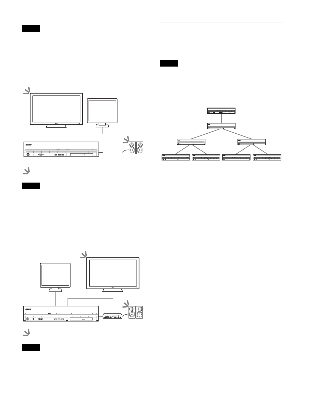
Example 3) When connecting an HDMI monitor
and analog RGB monitor (HDMI monitor used
for operations)
POWER 1 2 3NETWORK 1 2 3 4HDD 1 2 3 4 ERRORSTATUS REC
Audio amplifier
(connect to
audio output
connectors
(L/R))
: Audio output locations.
Notes
You can connect up to seven optional NSRE-S200 units
to the NSR-1200/1100/1050H in the following tree
configurations.
Note
The mini-SAS cable used for connection is supplied
with the NSRE-S200.
Connect NSRE-S200 expansions in the following order.
NSR-1200/1100/1050H
POWER 12 3NETWORK 12 34HDD 1 23 4 ERRORSTATUS REC
POWER 12 3NETWORK 12 34HDD 1 23 4 ERRORSTATUS REC
2
POWER 12 3NETWORK 12 34HDD 1 23 4 ERRORSTATUS REC
NSRE-S200
4675
POWER 12 3NETWORK 12 34HDD 1 23 4 ERRORSTATUS REC
POWER 12 3NETWORK 12 34HDD 1 23 4 ERRORSTATUS REC
NSRE-S200
1
NSRE-S200
3
POWER 12 3NETWORK 12 34HDD 1 23 4 ERRORSTATUS REC
POWER 12 3NETWORK 12 34HDD 1 23 4 ERRORSTATUS REC POWER 12 3NETWORK 12 34HDD 1 234 ERRORSTATUS REC
• Do not connect a monitor to HDMI monitor connector
2.
• When using HDMI monitors, be sure to connect the
HDMI monitor and turn it on before turning on the
unit.
Example 4) When connecting an HDMI monitor
and analog RGB monitor (analog RGB monitor
used for operations)
POWER 1 2 3NETWORK 1 2 3 4HDD 1 2 3 4 ERRORSTATUS REC
Audio amplifier
: Audio output locations.
Notes
• Do not connect a monitor to HDMI monitor connector
1.
• Do not connect a monitor to monitor connector 1 on
the front of the unit while the unit is on.
Connection Examples
29
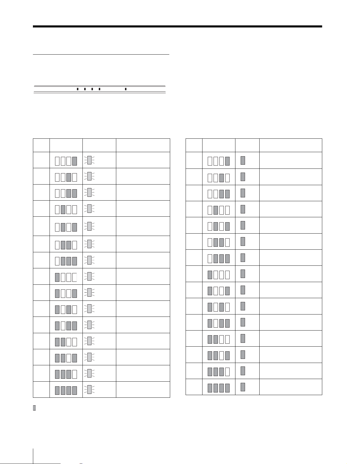
Miscellaneous
STATUS LED
When an error occurs with the unit, the ERROR LED on the front panel of the unit flashes or lights depending on the
error status, and the STATUS LED lights.
1 2 3 4 ERRORSTATUS
The STATUS LED indicates the following error situations.
Error codes displayed during boot stage
(The ERROR LED blinks when an error occurs
during boot.)
Error
STATUS
code
LED
1 Blinking
1234
2 Blinking CPU fan failure
1234
3 Blinking
1234
4 Blinking CMOS battery failure
1234
5 Blinking
1234
6 Blinking
1234
7 Blinking
1234
8 Blinking
1234
ERROR LED Possible Cause
Voltage power supply
failure
Defective memory
module
Video random access
memory (RAM) or
controller failure
Hard disk controller
failure
No bootable device
found
No bootable Operating
System found
Error codes displayed during operation stage
(The ERROR LED lights when an error occurs
during operation.)
Error
STATUS
code
LED
1 On Critical temperature
1234
2 On CPU fan failure
1234
3 On Power supply fan failure
1234
4On
1234
5 On Hard disk drive fan 1 failure
1234
6 On Hard disk drive fan 2 failure
1234
7 On Hard disk drive is damaged.
1234
8 On Reserved for future use
1234
ERROR
LED
Possible Cause
Voltage power supply
failure
9 Blinking
1234
A Blinking
1234
B Blinking
1234
C Blinking
1234
D Blinking Reserved for future use
1234
E Blinking Reserved for future use
1234
F Blinking
1234
One or more hard disk
failure
RAID OS volume
failure
Failure to start the X11
server
Failure to start the
application
RAID data volume
failure
indicates that the STATUS LED or ERROR LED is lit.
30
Miscellaneous
9 On Reserved for future use
1234
A On Reserved for future use
1234
B On Operating system error
1234
COn
1234
DOn
1234
E On RAID data volume failure
1234
FOn
1234
Application functioning
failure
[ERROR] lamp in “Main”
screen is lit
RAID data volume is being
restructured
 Loading...