

Page 1

Network Player
3-620-271-11 (1)
Operating Instructions
Before operating the unit, please read this manual
thoroughly and retain it for future reference.
NSP-100
© 2002 Sony Corporation
Page 2

WARNING
To prevent fire or shock hazard, do not
expose the unit to rain or moisture.
T o av oid electrical shock, do not open the
cabinet. Refer servicing to qualified
personnel only.
Caution
· When using a LAN cable: For safety , do not con nect to
a connector for peripheral device wiring that might
have ex cessive voltage.
· Danger of explosion if battery is incorrectly replaced .
Replace only with the sam e or eq uivalent type
recommended by the manufacturer.
Dispose of used batteries according to the
manufacturer's instructions.
IMPORT ANT
The nameplate is located on the bottom .
For the customer s in the USA
This equipment has been tested and found to c omply
with the limits for a Class A digital device, pursuant to
Part 15 of the FCC R u les. These limits are designed to
provide reasonable protection against harmful
interference when the equipment is operated in a
commercial environment. This equipment generates,
uses, and can radiate radio frequency energy and, if not
installed and used in accordance with the instruction
manual, may cause harmful interference to radio
communications. Operation of this equ ipme nt in a
residential area is likely to cause harmful interference in
which case the user will be required to correct the
interference at his own expense.
· EN55103-2: Electromagnetic Susceptibility
(Immunity)
This product is intended for use in the follo wing
Electromagnetic Environment (s):
E1 (residential), E2 (commercial and light industrial),
E3 (urban outdoors) and E4 (controlled E MC
environm ent ex. TV studio).
You are cautioned that any change s or modifications n ot
expressly approve d in this m anua l could void your
authority to operate this equipment.
The shielded interface cable recommended in this
manual must be used w ith this equ ipm e nt in order to
comply with the limits for a digital device pursuant to
Subpart B of Part 15 of FCC Rules.
For the customer s in Eur ope
This product wi th the CE m a r king comp l ies with both
the EMC Directi v e (89/336/E EC ) and the Low Voltage
Directive (73/23/EEC ) issued by the Com mission of the
European Comm u nity.
Compliance with these directi ves im plies conform ity to
the following Europea n standard s:
· EN60950: Product Safety
· EN55103-1: Electromagn etic Interference (Emission)
2
Page 3

Table of Contents
Overview
Features .................................................................. 4
Names and Functions of Parts ..............................5
Main Unit Front Panel and Left Side .................5
Main Unit Rear Panel .........................................6
Remote Controller ..............................................7
Operation
Preparations ...........................................................9
Remote Controller Preparations .........................9
Replacing the Battery .........................................9
Main Unit DIP Switch and Remote Controller
Settings ............................................................. 9
Starting Up and Initial Settings .........................10
Displaying the “MENU” Screen .........................11
Playing a Playlist .................................................12
Displaying the T itles of the Events During P laylist
Playback ......................................................... 12
Playing a Movie File ............................................13
Displaying a Still Image File ...............................13
Deleting Unwanted Playlists and Files ...............14
Deleting an Unwanted Playlist .........................14
Deleting Unwanted Movie and Still Image Files .
15
Setting the Operating Configuration (Setup) ....16
Displaying the “Setup” Screen .........................16
Setting the System Date and Time ................... 16
Making the “Delete Confirmation” Setting ...... 17
Making the “Display During Break” Setting ...17
Making the “Store Playout Log” Setting ..........17
Carrying Out “Playout Mode Setup (Playlists)” ..
18
Carrying Out Screen Adjustment .....................18
System Administrator Setup ..............................19
Displaying the “System Administrator Setup”
Screen ............................................................. 19
Carrying Out “Network Setup” ........................20
Carrying Out “RS-232C Setup” .......................20
Setting “Menu Language” ................................21
Activating “Automatic Delete” .........................22
Carrying Out “Delete All Data” ....................... 22
Carrying Out “Password Setup” .......................22
Others
Precautions ...........................................................26
Alarm Indications ................................................26
Specifications ........................................................27
Connections
Connecting the Power .........................................24
Examples of System Connection ........................24
3
Page 4

Overview
Features
The NSP-100 Network Player plays back (decodes)
video/audio data in MPEG format, outputting an analog
signal. It is the ideal digital content player for
advertizing, presentations, training, and other situations.
The following are the p rincipal features of this system.
High Image Quality
Plays MPEG-2 M P@ML enco ded movies and full-color
stills, realizing an image quality comparab le with that of
a DV D player.
Superimposed Movies, Stills, and Text
W ith a playlist, you can specify movies, stills, and
superimposed captions to be displayed simultaneously
on the monitor for specified durations.
Compact and Lightweight
The dimensions (width/height/depth) are 180 × 44 × 130
1
mm (7
1 kilogram (2 lb 3 oz), despite its large capacity.
/8 × 1 3/4 × 5 1/8), and the unit weighs only about
Large Capacity
The unit incorporates a 40-GB hard d isk dri v e. This
holds about nine hours of video compressed to a b it rate
of 8 Mbps, or about 18 hours of video 4 Mbps.
1) Figures for storage times are for storing movies only; depending on
how the system is used, the mov ie ca pa city may be less than these
figures.
1)
Wide Range of Interfaces Supported
• Analog video output: Component video (Y/R−Y/B
Y or RGB), S-video, and composite video outputs are
available. This allows a flexible choice of display
monitor .
• Analog audio ou tput: Two output channels (left and
right) are available.
• 100BA SE-TX : Ethernet con n ection is possible.
• RS-232C/GPI: This allows remote control of the
monitor and other external devices connected to this
unit.
Simple Operation From Remote
Controller
Operation is simple, using the supplied RM-NSP1
Remote Controller. The movie controls are intuitive,
being similar to those of a VTR.
One remote controller can be used to c ontrol two units.
−
4
Features
Page 5
Names and Functions of P arts
Main Unit Front Panel and Left Side
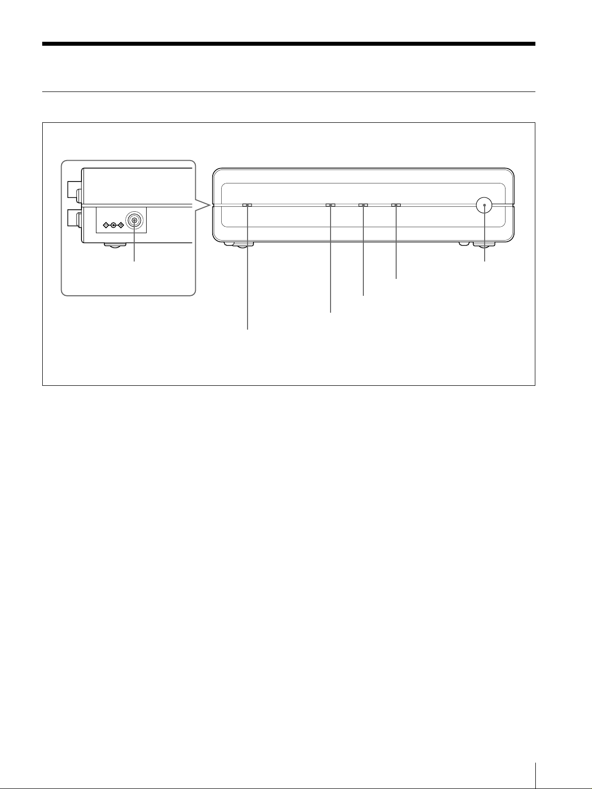
DC IN 12V
6 DC IN 12V connector
POWER indicator
1
1 POWER indicator
This lights when po w er is sup p lied to the un it.
2 NEW CONTENTS indicator
This indicator is off, lit, or flashing, to indicate the status
of new content d elivery.
Flashing: new data is being recei ved.
Lit: new data has arrived.
Off: at least one item of new data has been played or
deleted.
3 ACCESS indicator
This indicator flashes while data is being read or written
to the internal hard disk drive.
5 Remote control
optical receiver
4 ALARM indicator
3 ACCESS indicator
2 NEW CONTENTS indicator
4 ALARM indicator
This flashes or lights when a system error has oc curred.
Flashing: A recoverable error occurred.
Lit: An unrecoverable error occurred.
5 Remote contr o l op tical receiver
When operating this unit with the supplied rem ote
controller, point the remote co ntroller at this recei ver.
6 DC IN 12V connector
Connect the DC cable of the sup plied AC adapter.
Names and Functions of Parts
5
Page 6
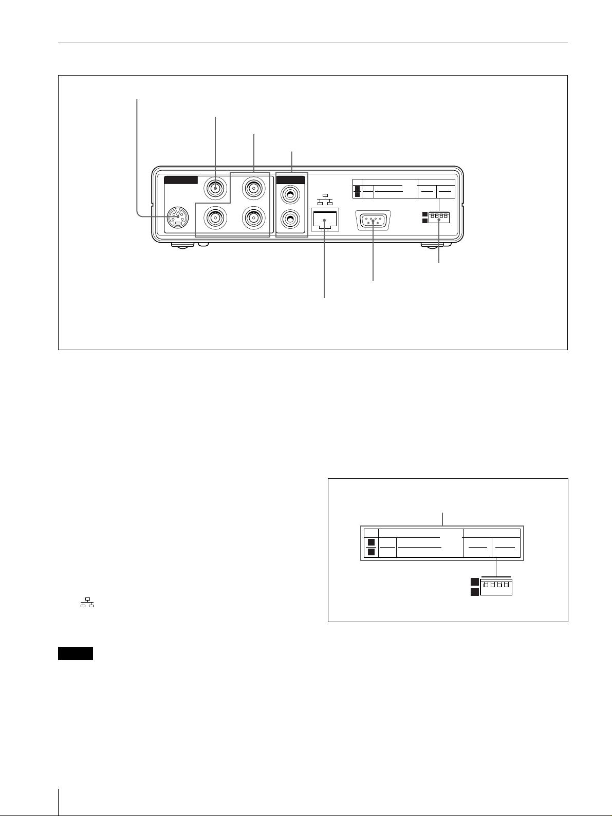
Main Unit Rear Panel
1 S VIDEO connector
COMOPOSITE connector
2
G/Y, R/R
3
−
4 AUDIO OUT 1 and 2 connectors
Y, B/ B−Y connector
VIDEO OUT
COMPOSITE
S-OUT
R/
R-Y
G/Y
B/
B-Y
AUDIO OUT
1
2
1 S VIDEO (S-video outp ut) connector (m ini-DIN
4-pin)
This outputs the playback video as an S-video signal.
2 COM OPOSITE connector (BNC type)
This outputs the playback video as an analog com posite
signal.
Y, B/B−Y (component video output)
3 G/Y , R/R
−
connector (BNC type)
This outputs the playback video as an analog component
signal. A DIP switch setting controls whether this is Y/
Y/B−Y signals or RGB signals.
−
R
4 A U DIO OUT 1 and 2 connectors (pin jack s)
This outputs the playback audio as an analog signal. For
a stereo signal, connector 1 outputs the left channel, and
connector 2 the right channel.
5 (network) connecto r (RJ-45 modular jack)
This is a 100BASE-TX connector for network
(Ethernet) connection.
Caution
When using a LAN cable: For safety, do not co nnec t to
a connector for peripheral device wiring that might hav e
excessive voltage.
6 RS-232C/G PI (ge nera l-pur p ose interface)
connector (D-sub 9-pin, male)
VIDEO IRD REMOTE
1
COMPONENT
NTSC
2
RGB
PAL
RS-232C/GPI
6 RS-232C/GPI connector
5 Network connector
ON
OFF12
1
2
7 DIP switches
Connect to the D-sub 9-pin connector o f a plasm a
display or video monitor.
7 DIP switches
The settings of the four switches relate to the output
video signal format, output component video signal, and
remote controller. The diagram of DIP sw itch settings
above the sw itches shows the significance of the two
positions (“1” and “2”) for each switch.
DIP switch setting diagram
1
2
VIDEO IRD REMOTE
COMPONENT
NTSC
PAL
RGB
ON
OFF12
1
2
VIDEO (outp u t vide o signal for m at/outpu t
component video signal settings)
NTSC/P AL (leftmost sw itch): Select the output video
signal format.
COMP ONENT/RGB (second switch from left):
Y/B−Y signal or RGB signal
Select output of a Y/R
from the G/Y, R/R
−
Y, B/B−Y connector.
−
IRD REMOTE (remote controller settings)
6
Names and Functions of Parts
Page 7
ON/OFF (third switch from left): Enable (ON) or
disable (OFF) the remote controller.
1/2 (rightmost switch): When using two NSP-100
units, to select the unit that responds to the remote
Remote Controller
controller, set different remote controller codes for
them.
For details, see “Preparations” (page 9).
Note
Using the remote controller to control the N SP-100
requires settings of both the NSP-100 rea r panel D IP
switches and the remote controller.
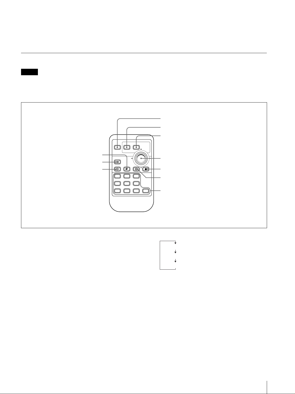
DISPLAY
LIST MENU
0 PLAY button
9 PAUSE button
8 Reverse shuttle
playback button
PAUSE
PLAY
123
456
7890
For details, see “Preparations” (page 9).
1 DISPLAY button
2 LIST button
3 MENU button
PUSH
ENTER
4 ENTER/b, B, v, V control
STOP
STOP button
5
Forward shuttle playback button
6
Numeric buttons
7
1 DISPLAY button
During movie/still playback: P ressing this button
displays the title of the movie/still being played.
Press once more to clear the display.
During playlist playback : Pressing this button displays
the numerical position of the current playlist in the
list of playlists shown on the “Playlists” screen.
(Example: “0003/0010” means playing playlist 3
out of 10 playlists.) Press once more to clear the
display.
2 LIST button
While the standby screen is displayed: P ressing this
button shows the last displayed list screen.
Subsequent presses change the d isplayed list screen,
in the following sequence.
“Playlists” screen (list of playlists)
“Video” screen (list of movie files)
“Graphics” screen (list of still image files)
During playlist playback: Pressing this button displays
details of the playlist. Press once more to clear the
display.
3 MENU button
When the menu is not displayed: P ressing this button
switches to menu m ode, and the “MENU” screen
appears.
When the m enu is displayed: Pressing this button
switches out of menu m od e, and the menu display
disappears.
For details of the menu, see “Operation” (page 9).
Names and Functions of Parts
7
Page 8

4 ENTER/b, B, v, V control
The center of this control functions as an ENT ER
button. The outer portions close to the arro w indications
function as arrow b uttons. (In this m an ual, the center of
this control is referred to as the ENTER button and the
outer portions are referred to as the b, B, v and V
buttons, respectively.)
ENTER button
While the “Playlists” screen, “Video” sc reen, or
“Graphics” screen is displayed: P ressing this
button plays the playlist, movie, or still image that is
selected (shown in reverse video).
While the menu is displayed : Pressing this bu tton
confirms the selection of the item shown in reverse
video, and changes the menu display.
b, B, v and V button s
These function as follows.
Button While a list
b Move to
B Move to next
v Select the line
V Select the line
a)“Playlists” screen , “V i de o” scre en, an d “G r ap h ic s” scr ee n.
b)For details of the m enu, see “Operation” (page 9) and follo w ing.
c)For details of screen adjustment, see page18.
a)
screen
displayed
previous page
page
above
below
is
In the menu
display
Change the
setting of the
selected item
Change the
setting of the
selected item
Select the item
above
Select the item
below
b)
In screen
adjustment
c)
mode
Move the screen
position to the
left / reduce the
screen width
Move the screen
position to the
right / increase
the screen width
Move the screen
position up /
increase the
screen height
Move the screen
position down /
reduce the
screen height
of the corresponding number (which appears in
reverse video).
While the “MEN U” screen is displayed: Y ou can use
these buttons to select the item of the corresponding
number. The display changes as soon as a selection
is made.
8 Reverse shuttle playback button ( )
Press this during movie playback to switch to h ighspeed play (shuttle) in the reverse direction.
During shuttle playback, the audio is muted.
9 P AUSE b u tton
Press this button during playback, to pause play back.
Press once more to resum e playb ack.
q; PLAY button
While the standby screen is displayed: Pressing this
button in the standby screen plays the specified
playlist ( PLAY button playback ).
For details of the PLAY button playback, see page 12.
While playback is paused: P ressing this button
resumes playback.
While the “Playlists” screen, “Video” scr een, or
“Graphics” screen is displayed: The selected
playlist, movie or still is played.
5 STO P b utton
Press this button during playback, to stop playbac k.
6 Forward sh uttle playback button ( )
Press this during movie playback to switch to highspeed play (shuttle) in the forward direction.
During shuttle playback, the audio is muted.
7 Numeric buttons (0 to 9)
Use these buttons to select an item displayed o n the
screen, make num eric settings, enter a password, and so
on.
While the “Playlists” screen, “Video” sc reen, or
“Graphics” screen is displaye d: You can use these
buttons to select the playlist, movie file, or still file
8
Names and Functions of Parts
Page 9
Operation
Preparations
This section describes the preparations for operating the
NSP-100 with the supplied rem o te controller, after
making the required connections (see page 24).
When using the function for playlist editing or content
distribution, refer to the Help information for the BZNP100LE (supplied) or BZNP -100 (not supplied) N etwork
Player Management So ftware
1) In the remaind er of this manual, BZNP-100LE and BZ NP-100 are
referred to together, as th e BZNP-100 Software.
Remote Controller Preparations
The remote controller is supplied with a CR 2025 lithium
battery and insulating film installed. Removing the
insulating film allow s the battery to be used.
1)
.
Caution
The battery may burst if incorrectly replaced.
Replace only with the sam e or equ ivalent type
recommended by the manufacturer.
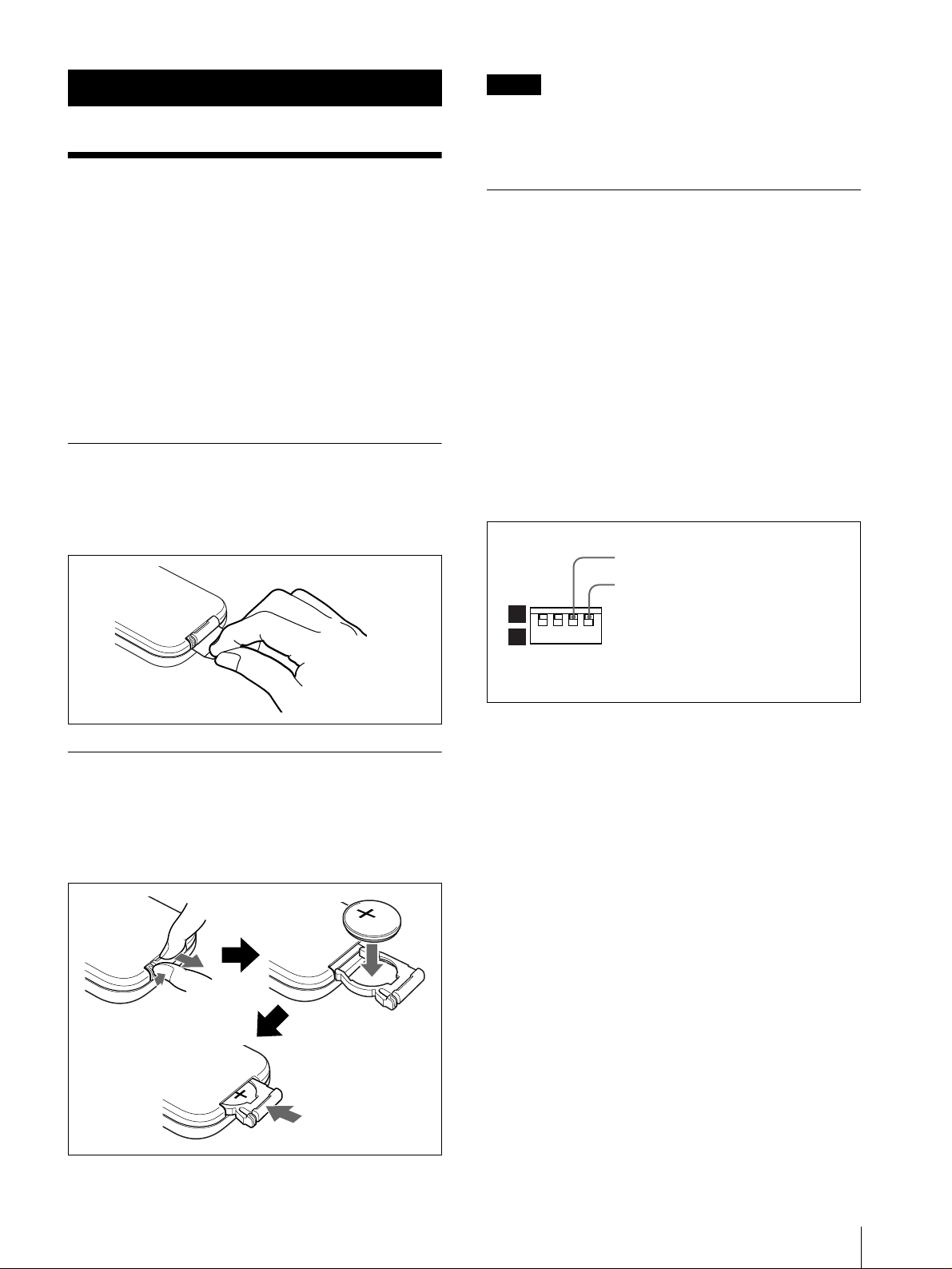
Main Unit DIP Switch and Remote
Controller Settings
To operate the NSP-100 with the remote con troller , in
the DIP switches on the rear panel of the main unit, set
the third switch from the left to the 1 position (ON ).
Then set the remote controller to correspon d w ith the
code number setting of the rightmost switch as follo w s.
When the cod e nu mber is 1 (the switch is in the “1”
position): Hold down the STOP and PAUSE
buttons on the remote controller, then press numeric
button 1.
When the cod e nu mber is 2 (the switch is in the “2”
position): Hold down the STOP and PAUSE
buttons on the remote controller, then press numeric
button 2.
Replacing the Battery
On the back of the remote controller, pull out the battery
holder. Insert the C R 202 5 lithium b attery with the
positive side up, then return the b attery holder to its
original position.
Set to the “1” position (ON).
To correspond with the setting of this
switch, press numeric button 1 or 2 on
1
2
the remote controller while holding
down the STOP and PAUSE buttons.
When operating two NSP-100 units with a
single remote controller
Set the code number to 1 on on e of the NSP-100 units,
and set the code number to 2 on the other unit. T o switch
the remote controller from one unit to the other, use the
same method as above.
Preparations
9
Page 10

Starting Up and Initial
Settings
When you con nect a m o n itor to the unit, and power on
for the first time, the starting screen appears and it is
then followed b y the initial setting screen.
r
W ith the b and B b uttons, select whether or not the
3
system is connected to a netw ork, then press the
ENTER button.
• If you select “No, ” the screen changes as follows.
In this case, skip to st e p 9.
To return to the previous screen
To return to the previous screen instead of
advancing to step 9, press the b button.
• If you select “Y es, ” next press the ENTER b utton.
The “Network Setup” screen reappears.
When the initial setting screen appears, carry out the
following procedure using the remote controller.
W ith the b and B buttons, select the language y ou
1
want to use in the men u s, and press the E NTER
button.
This confirms the langu age se lection, and the
“Network Setup” sc reen ap pears.
Using the v an d V buttons, select the item you want
4
to set, then press the ENTE R button.
The setting can now be ch anged .
Using the b and B buttons, select the group to set
5
within the selected item.
Enter the setting with the numeric buttons (0 to 9).
6
Alternatively, adjust the setting with the v and V
buttons.
For details of the settings to be entered, consult
your system administrator.
Press the ENTER button.
2
It becomes possible to select whether or no t to use
a network (that is, whether or no t the system is
connected to a network).
10
Starting Up and Initial Settings
Press the ENTER button.
7
This confirms the setting of the selected item .
Repeat steps 4 to 7 until all of the required items
8
have been set.
Page 11

Press the MENU button.
9
To enable the new network settings, a me ssage
prompt appears, asking if you want to reset the unit.
Select “Yes” to reset immediately or “No” to reset
10
later, then press the ENT E R button.
The standby screen appears after a reset (for “Y es”)
or immediately (for “No” ).
Displaying the “MENU”
Screen
In the standby screen, press the MENU button.
The “MEN U” screen a ppears.
In the “MENU” scree n, you can select the next screen to
be displayed. The screens to be displayed are sho wn in
the fo l lowing table.
Screen to be selected Section with details
1. “Playlists” screen “Playing a Playlist” (page 12 )
2. “Video” screen “Playing a Movie File” (page 13)
3. “Graphics” screen “Displaying a Still Image File”
(page 13)
4. “Delete Files” screen “Deleting Unwanted Playlists and
Files” (page 14)
0. “Setup” screen “Setting the Operating
Configuration ( Setup)” (page 16)
T o c hange the design of the standby screen
Use the BZNP-100 Software.
For details, refer to the Help information for the BZNP100 Software.
T o exit the “MENU” screen
Press the MENU button.
Note
If no remote controller operation is made for about five
minutes during the display of any m e nu scree n , the
standby screen appears.
Alarm indications
An alarm icon appears at the lo w e r left of the m enu
screen to indicate an abnormal tem perature w ithin the
unit or other problems.
For details, see page 26.
Alarm icon
Displaying the “MENU” Screen
11
Page 12

Playing a Playlist
In the “Playlists” screen, you can select a desired
playlist, and play it.
You can also make the follo w ing specif ications.
• Autom atic playb ack at power on
Playlist that starts playback automatically when the
unit is powered on
• PLAY button playback
Playlist that starts playback if you press the PLAY
button in the standby screen
Using the v a nd V buttons, select the playlist you
2
want to play.
Press the ENTER button or PLAY button.
3
This starts playback of the desired playlist.
When playback ends, the “Play lists” screen
reappears.
To stop during playback
Press the STOP button.
Playback stops, and the “Playlists” screen appears.
For details of these settings, see “Carrying Out
“Playout Mode Setup (Playlists)”” (page 18).
T o select a desired playlist and play it, use the following
procedure.
In the “MEN U” screen, carry ou t an y o f the
1
following.
• Press numeric button 1.
•Using the v and V buttons, sele ct “1. Playlist s ,”
and press the ENTER button.
The “Playlists” screen appears.
Note
If you interrupt automatic playlist playback started as
scheduled with BZNP-100 Software and about five
minutes elapse without any rem ote controller operation,
the standby screen appears. An y subseq uent sche duled
playback begins at the set time.
Displaying the Titles of the Events
During Playlist Play back
Press the LIST button.
The titles of the even ts constituting the playlist being
played appear.
Still image file
indication
Movie file
indication
12
1
2
3
1 New playlist indication
2 Automatic playback at power on indication
3 PLAY button playback indication
1) The new playlist indication shows playlists that have been added
since the last time the playlist display was shown.
2) This is a display for example only. If this dis play were actually
present, playback would have started when the unit was powered on.
Pla ying a Playlis t
1)
2)
To return to the playlist playback screen
Press the LIST button.
T o play from the beginning of a desired event
Using the v and V buttons, select the event, then press
the ENTER b utton o r PL AY button.
Page 13

Playing a Movie File
Displaying a Still Image
In the “Video” screen, you can select a desired movie
file, and play it back.
Use the following p rocedure .
In the “MENU ” screen, carry ou t an y of the
1
following.
• Press numeric button 2.
•Using the v and V b uttons, select “2. V ideo, ” and
press the ENTER b u tton.
The “Video” screen appears.
File
In the “Graphics” screen, you can select a desired still
image file, and display it.
Use the following pro cedure.
In the “MEN U” screen, carry ou t an y o f the
1
following.
• Press numeric button 3.
• Using the v and V buttons, select “3. Graphics,”
and press the ENTER button.
The “Graphics” screen appe ars.
New movie file
indication
To change the page
When the “Video” screen is divided into a number
of pages, to change the page, press the b or B
button.
Using the v and V buttons, select the movie f ile
2
you want to play.
Press the ENTER b u tton or PL AY button.
3
This starts playback of the selected movie f ile.
When playback ends, the “V ideo” screen reapp ears.
To stop during playback
Press the STOP button.
Playback stops, and the “Video” screen appears.
New still image
file indication
To change the page
When the “G raphics” sc reen is di vided into a
number of pages, to change the page, press the b or
B bu tton.
Using the v and V buttons, select the still image file
2
you want to play.
Press the ENTER button or PLAY button.
3
The selected still image file is displayed.
To end the display
Press the STO P button.
When the display ends, the “G rap h ics” screen
reappears.
Playing a Movie File / Displayin g a Still Im age File
13
Page 14

Deleting Unwanted
Playlists and Files
You can delete unwanted playlists and m ovie and still
image files.
Deleting an Unwanted Playlist
Use the following pro cedure.
In the “MEN U” screen, carry ou t an y o f the
1
following.
The “Delete Files” screen appears.
Carry out any of the following.
2
• Press numeric button 1, then press the E N T ER
button.
• Using the v and V b uttons, se lect “1. Playlists,”
and press the ENTER button.
The screen changes as follo ws.
• Press numeric button 4.
•Using the v and V buttons, select “4. Delete
Files,” and press the E NTER button.
When a p assw ord has been set
A password entry window appears.
In this case, enter the password with the numeric
buttons, and press the ENTE R button.
Using the v and V butto ns, se lec t the playl ist to be
3
dele ted.
Press the ENTER button.
4
A message appears, prom p ting you to confirm the
dele tion.
The titles of the ev ents con stituting the selected
playlist appear in the background.
14
Deleting Unwanted Playlists and Files
Note
In the “Setup” screen, if item 2. “Delete
Confirmation” is set to “N o,” this confirmation
message does not appear.
Page 15

Using the b and B b uttons, select “Yes” or “No,”
5
and press the ENTER button.
• “Yes”: the playlist selected in step 3 is deleted.
• “No”: the playlist is not deleted, and the screen
before executing step 4 reappears.
Deleting Unwanted Movie and Still
Image Files
Use the following p rocedure .
Carry out step 1 o f the proce dure in the fore go ing
1
section “Deleting an Unw an ted Playlist.”
The “Delete Files” screen appears.
Carry out any of the follo wing.
2
• Press numeric button 2 or 3, then press the
ENTER b u tton.
•Using the v and V buttons, select “2. V ideo” or
“3. Graphics, ” and press the ENTER button.
Depending on the selection, the “V ideo” screen for
movie file deletion or “G raph ics”screen for still
image file deletion appears.
To change the page
When the “Video” screen or “Graphics” screen is
divided into a numb er of pages, to change the page,
press the b or B button.
Using the b and B buttons, select the movie or still
3
image file to be deleted.
Press the ENTER button.
4
A message appears, pro mpting you to confirm the
deletion.
The file to be deleted appears in the background , as
a movie or still image. A t the end of a movie, the
last frame remains stationary.
Note
In the “Setup” screen, if item 2. “Delete
Confirm ation” is set to “N o,” this confirmation
message does not appear.
Using the b and B buttons, select “Ye s” or “N o,”
5
and press the ENTER button.
• If you selected “Y es, ” the movie or still image file
selected in step 3 is de le te d .
• If you selected “No, ” the f ile is not deleted, and
the screen before executing step 4 reappears.
Deleting Unwanted Playlists and Files
15
Page 16

Setting the Operating
Configuration (Setup)
T o make settings relating to the operating configuration,
display the “Setup” screen.
Displaying the “Setup” Screen
To display the “Setup” screen, in the “MENU” screen,
carry out any of the following operations.
• Press numeric button 0.
•Using the v and V buttons, select “0. Setup,” and
press the ENTER button.
Settings that
can be
selected
“1. System
Date/Time”
“2. Delete
Confirmation”
“3. Display
During Break”
“4. Store
Playout Log”
“5. Playout
Mode Setup
(Playlists)”
“6. MENU
Screen Setup”
“7. System
Administrator
Setup”
Function of setting See page
Set the system date and time. 16
Select whether or not to display
a confirmation message when
deleting a playlist, movie, or
still image.
Select whether to display the
last still image or a black
background durin g a br eak in a
playlist (while waiting for the
next event playback).
Select whether to save a playout
log.
Set a playlist for automatic
playback at power on, or for
PLAY button playback mode.
Adjust the menu screen po sition
and size.
Carry out system administrator
setup.
To exit the “Setup” screen
Press the MENU button.
17
17
17
18
18
19
The “Setup” screen appears.
Settings selected in the “Setup” screen
The settings selected in the “Setup” screen are as
follows. For details, see the respecti ve pages.
Setting the System Date and Time
To set the system date and time, use the following
procedure.
In the “Setup” screen, carry out any of the
1
following.
• Press numeric button 1, then press the E N T ER
button.
• Using the v and V b uttons, select “1. Sy stem
Date/T ime,” and press the ENTER button.
The screen no w allows the date and time to be set.
16
Setting the Operating Configuration (Setup)
Using the b and B buttons, select the item to set
2
(date or time).
Page 17

With the numeric buttons, enter the req uired setting
3
value.
Alternatively , use the v and V b utt on s to a dju st the
value.
When the setting is complete, press the E N TER
4
button.
This completes the setting.
Making the “Delete Confirmation”
Setting
T o select whether or not a confirmation message appe ars
before you delete an unwa nted f ile or playlist, use the
following procedure.
In the “Setup” screen, carry out any of the
1
following.
• Press numeric button 2, then press the EN TE R
button.
•Using the v and V b u tt on s, s ele c t “2 . D ele te
Confirmation,” and press the ENTER button.
In the “Setup” screen, carry out any of the
1
following.
• Press numeric button 3, then press the ENTE R
button.
•Using the v and V buttons, sele ct “3. Display
During Break,” and press the ENTER button.
The setting can now be changed.
Using the b and B buttons, select “Still” or
2
“Black.”
Press the ENTER button.
3
The setting can now be ch ange d.
Using the b and B b uttons, select “Yes” or “No. ”
2
• “Yes”: Display a confirmation message before
deleting.
• “No”: Do not display a confirmation message
before deleting.
Press the ENTER button.
3
This confirms the setting.
Making the “Display During Break”
Setting
This confirm s the setting.
Making the “Store Playout Log”
Setting
Select whether or not to save a playout log for this unit.
The playout logs are handled by the B Z NP -100
Software.
For details, see the BZNP-100 H elp information.
Use the following pro cedure.
In the “Setup” screen, carry out any of the
1
following.
• Press numeric button 4, then press the ENTE R
button.
•Using the v and V buttons, select “4. Store
Playout Log,” and press the ENTER button.
The setting can now be changed.
During a break in a playlist (while w a iting for the ne x t
event playback), select w h ethe r to display the last still
image or a black background.
Use the following p rocedure .
Setting the Operating Configuration (Setup)
17
Page 18

Using the b and B buttons, select “Y e s” or “N o.”
2
• “Yes”: Save a playout log.
• “No”: Do not sav e a p layout log.
Press the ENTER button.
3
This confirm s the setting.
Carrying Out “Playout Mode Setup
(Playlists)”
You can make the follo wing settings for the selected
playlist.
• Autom atic playb ack at power on
A playlist that begins to play automatically w hen this
unit is powered on
• PLAY button playback
A playlist that plays if you press the PLAY button in
the standby screen.
Once playback of a playlist is started based on these
settings, it is repeated until the STOP button is pressed.
When you press the S TOP bu tton, playback ends and the
standby screen reappears.
The playout mode setup window appears.
Using the v a nd V buttons, select “Power O n” o r
3
“PLAY Button.”
• “Power On”: Automatic playback at power on
• “PLAY Button”: PLAY b u tton p layback
To remove an ex isting setting
Select “Mode Off.”
Press the ENTER button.
4
This confirm s the setting.
Use the following pro cedure.
In the “Setup” screen, carry out any of the
1
following.
• Press numeric button 5, then press the ENTE R
button.
•Using the v and V buttons, select “5. Playou t
Mode Setup (Playlists),” and press the ENTER
button.
The “Playout Mode Setup (Playlists)” screen
appears.
Using the v and V buttons, select the playlist for
2
which you wa nt to m ake the setting, and press the
ENTER button.
Carrying Out Screen A djustment
To adjust the menu screen position or size, use the
following procedure.
In the “Setup” screen, carry out any of the
1
following.
• Press numeric button 6, then press the E N T ER
button.
• Using the v and V buttons, select “ 6. MENU
Screen Setup,” and press the ENTER bu tton.
The “Position/Size” selection windo w appea rs.
To return the menu screen position and size to
the default settings
Select “Default Settings, ” press the ENTER button,
and then skip to step 6.
18
Setting the Operating Configuration (Setup)
Page 19

Using the v a nd V buttons, select either “Position”
2
or “Size, ” and press the ENTER button.
System Administrator
The display color of the selected item changes.
Adjustment procedure
Normally, it is recommended to select “Position
Adjustment” first, and position the top left corner of
the screen, then proceed to size adjustment.
Adjust the screen position or size.
3
• If you have selected “Position, ” using the v, V, b
and B bu ttons, adjust the position of the screen
horizontally and vertically. The coordinates are
shown in parenthesis.
• If you have selected “Size,” use the v and V
buttons to adjust the screen height, and the b and
B buttons to adjust the screen width. The
dimensions in pixels are shown in parenthesis.
To cancel the adjustment and exit the men u
screen
Press the MENU button.
Press the ENTER button.
4
The adjusted values are set an d the screen to select
the item to be adjusted reappears.
Setup
To carry out system administrator setup, display the
“System Administrator Setup” screen.
Displaying the “System
Administrator Setup” Screen
T o display the “System A dministrator Setup” screen , in
the “Setup” screen, carry out any of the following
operations.
• Press numeric button 7, then press the ENT ER b utton.
•Using the v and V buttons, select “7. System
Administrator Setup,” and press the ENTER button.
When a password has been set
A password entry wind ow appears.
As required to adjust the other item, repeat steps 2
5
to 4.
When the adjustments are c omplete, press the v
6
button to select “Set,” then press the ENTER
button.
The adjustments are reflected in the screen display .
In this case, enter the password with the n umeric
buttons, and press the EN T E R button.
The “System Administrator Setup” screen appears.
To return to the “Setup” screen
Carry out any of the follow ing operations.
• Press numeric button 1, then press the ENT ER b utton.
•Using the v and V buttons, select “1. Back to Setup
Menu,” and press the ENTER button.
System Administrator Setup
19
Page 20

Settings sele cted in the “Sys tem Adm inistrator
Setup” screen
The settings selected in the “System A d m inistrator
Setup” screen are as follow s. For details, see the
respective pages.
Settings that
can be
selected
“2. Network
Setup Menu”
“3. RS-232C
Setup Menu”
“4. Menu
Language”
“5. Activate
‘Automatic
Delete’”
“6. Delete All
Data”
“7. Password
Setup”
Function of setting See page
This makes settings related to
the network.
This makes settings related to
the RS-232C/GPI connector
and plasma display.
Select Japanese or English as
the menu language.
Select whether or not to
enable the deletion of files for
which an automatic deletion
date is set.
This deletes all data from the
unit.
This sets a password. 22
20
20
21
22
22
Carry out steps 4 to 8 of the procedure in “Starting
2
Up and Initial Settings” (page 10).
Carry out any of the following.
3
• T o exit the menu display , press the MENU button.
• To return to the “Sys te m Admin i s t r a tor Setup”
screen, press numeric button 1, or using the v and
V b u t to n s , s elect “1. Back t o System
Administrator Setup,” and press the ENTER
button.
To enable the new network settings, a m essage
prompt appears, asking if you wa nt to reset the unit.
Carrying Out “Network Setup”
To make the settings relating to the network, use the
following procedure.
In the “System Ad ministrator Setup” screen, carry
1
out any of the follo wing.
• Press numeric button 2, then press the ENTE R
button.
•Using the v and V buttons, select “2. Network
Setup Menu,” and press the ENTER button.
The “Network Setup” screen appears.
To reset immediately , select “Yes”; to reset later ,
4
select “No.”
The standby screen or “System Administrator
Setup” screen appears after a reset (for “Yes”) or
immediately (for “No”).
Carrying Out “RS-232C Setup”
In the “RS-232C Setup” screen, you c an select the
following settings relating to control.
• RS-232C Protocol control
Select this when using the dedicated control protocol.
• Maintenance
Select this when the RS-232C/GPI connector is to be
used for maintenance.
• External (GPI) device control
Select this when the RS-232C/GPI connector is to be
used for control of an external de vice.
•Plasma control
Select this when using a plasma display.
Use the following proc edure.
To return to the “System Adm inistrator Setup”
screen
Carry out any of the following.
• Press numeric button 1, then press the ENTE R
button.
•Using the v and V buttons, select “1. Back to
System Administrator Setup,” and press the
ENTER button.
20
System Administrator Setup
In the “System Administrator Setup” screen, carry
1
out any of the following.
• Press numeric button 3, then press the E N T ER
button.
• Using the v and V buttons, select “ 3. RS-232C
Setup Menu,” and press the ENTER b u tton.
Page 21

The “RS-232C Setup” screen app ears.
To return to the “System Ad m inistrator Setup”
screen
Carry out any of the follo wing.
• Press numeric button 1, then press the EN TE R
button.
•Using the v and V b uttons, select “1. Back to
System Administrator Setup,” and press the
ENTER b u tton.
Carry out any of the follo wing.
2
• Press numeric button 2, then press the EN TE R
button.
•Using the v and V b uttons, select “2. Control, ”
and press the ENTER button.
The setting can now be ch ange d.
• Press numeric button 1, or using the v and V buttons,
select “1. Back to System Administrator Setup,” and
press the ENTER button.
T o enable the new RS-232C settings, a message prompt
appears, asking if you want to reset the unit.
To reset immediately , select “Yes”; to reset later , select
“No. ”
The standby screen or “S ystem Administrator Setup”
screen appears after a reset (for “Yes”) or immediately
(for “No”).
Setting “Menu Language”
You can select Japanese or English as the menu
language.
Using the b and B b uttons, select the desired
3
setting, and press the ENTER b utton.
• When anything other than “Plasma Control” is
selected, the setting is confirmed.
• When “Plasma Con trol” is selected, continue to
step 4.
Using the b and B b uttons, select the plasma
4
display to be controlled, and press the ENTER
button.
This confirms the setting.
T o exit the “RS-232C Setup” screen
Carry out any of the following operations.
• Press the MENU button.
Use the following pro cedure.
In the “System Ad ministrator Setup” screen, carry
1
out any of the follo wing.
• Press numeric button 4, then press the ENTE R
button.
•Using the v and V buttons, select “4. Menu
Language,” and press the ENTER button.
The setting can now be changed.
Using the b and B buttons, select “Japanese” or
2
“English” as the menu language.
Press the ENTER button.
3
System Administrator Setup
21
Page 22

This confirm s the setting.
Activating “Automatic Delete”
Select whether or not to enable the deletion o f files for
which an automatic deletion date is set.
For details of the automatic deletion setting, refer to the
Help i n formation for the BZNP-100 Sof t ware.
Use the following pro cedure.
In the “System Ad ministrator Setup” screen, carry
1
out any of the follo wing.
• Press numeric button 5, then press the ENTE R
button.
•Using the v and V buttons, select “5. Activate
‘ A utomatic Delete,’” and press the ENTER
button.
A message appears, prom p ting you to confirm the
dele ti o n of all data.
Using the b and B buttons, select “Yes” or “No,”
2
and press the ENTER button.
• “Yes”: All data is deleted from the unit.
• “No”: The data is not deleted, and the original
screen reappears.
The setting can now be changed.
Using the b and B buttons, select either of the
2
following.
• “Yes”: Enable automatic deletion settings.
• “No”: Disable automatic deletion settings.
Press the ENTER button.
3
This confirm s the setting.
Carrying Out “Delete All Data”
This d e le tes a ll da ta from the unit.
Use the following pro cedure.
Carrying Out “Password Setup”
Use the following proc edure.
In the “System Administrator Setup” screen, carry
1
out any of the following.
• Press numeric button 7, then press the E N T ER
button.
• Using the v and V buttons, select “ 7. Passwor d
Setup, ” and p ress the E N T E R button.
The “Password Setup” wind o w appears.
W ith the nu meric buttons, enter a four-d igit
2
password, and press the ENTER button.
In the “System Ad ministrator Setup” screen, carry
1
out any of the follo wing.
• Press numeric button 6, then press the ENTE R
button.
•Using the v and V buttons, select “6. Delete All
Data, ” and press the ENTER button.
22
System Administrator Setup
To correct an en try
Press the b button.
Each time you press this b utton, the last digit is
dele ted.
Enter the password created in step 2 once m ore, and
3
press the ENTER button.
This sets the password.
Page 23

T o can cel the pass word
In steps 2 and 3, press the ENTER button without
entering any number.
System Administrator Setup
23
Page 24

Connections
Examples of System
Connection
Connecting the Power
Using the supplied AC adapter and AC cable, make the
connections shown in the following figure.
T o DC IN 12 V connector
DC cable
To 100 V AC supply
AC adapter
AC cable
T o A C input connector
For distributing content and playlists
through a TCP/IP network
Audio monitor
system
RS-232C
RS-232C/GPI
Ethernet
Video input connector
Video output
connectors
(Y/R
Y/B−Y,
−
RGB, S VIDEO,
COMPOSITE)
Plasma display/
video monitor
AUDIO OUT
1, 2
(Network)
Notes
• T o operate this system requires the BZNP-100 Software.
• The connection cables are not supplied with this unit.
24
Connecting the Pow er / Examples of System Connection
Page 25

For distributing content and playlists
through Ethernet to multiple NSP-100
units
Video monitor
Audio monitor
Ethernet
Computer
NSP-100
Video monitor
Audio monitor
NSP-100
Video monitor
Audio monitor
NSP-100
Notes
• The BZNP-100 Software must be installed in the computer.
• The connection cables are not supplied with this unit.
Examples of System Connection
25
Page 26

Others
Precautions
On operation and storage locations
Avoid operation or storage in any of the follow ing
places.
• Location subject to extremes of temp erature
(operating temperature range 5
F))
°
104
• Location subject to direct sunlight for long periods, or
close to heating appliances (Note that the interior of a
car left in summer with the windows closed can
C (122°F).)
exceed 50
°
• Damp or dusty places
• Location subject to severe vibrations
• Location near equipment generating strong
electromagnetic emissions
• Location near transmitting stations generating strong
radio wav e s
Operate the unit in a horizontal position
This unit is designed to be operated in a horizontal
position. Do not operate it on its side, or tilted through
an excessiv e ang le (e xce eding 2 0
Dropping the unit, or otherwise imparting a v iolent
shock to it, is likely to cause it to malfunction.
Avoid violent impacts
Dropping the unit, or otherwise imparting a v iolent
shock to it, is likely to cause it to malfunction.
Do not obstruct ventilation openings
To prevent the unit from ov e rheating, do not ob struct
ventilation openings, by for e xample wrapping the unit
in a cloth while it is in operation.
On cleaning
If the casing or panel is dirty, wipe it gently with a soft
dry cloth. In the event of e x trem e dirt, use a cloth
steeped in a neutral detergent to remove the dirt, then
wipe with a dry cloth. Applying alcoh ol, thinners,
insec t icides, or othe r volatile solvents may result in
deforming the casing or damaging the f inish.
On repacking and shipping
Save the original shipping carton and pac king m aterial;
they will come in handy if you ever have to ship your
unit.
For maxim um protection, repack your unit as it was
originally packed at the factory, and take care not to
impa rt v io le n t sh o ck s in transit.
C to 40°C (41°F to
°
).
°
Alarm Indications
The temperature range for guaranteed o peration of this
unit is from 5
outside this temperature range, the life of the unit may
be reduced, or the internal hard disk drive may fail.
The following alarm icons appear at the lo wer left of the
menu screen to indicate an abnormal temperature w ithin
the unit or other problems.
Indication Meaning an d action to tak e
C to 40°C (41°F to 104°F). If operated
°
High temperature warning
The internal temperature has risen into the range
65
to 79
C
°
Check that the ventilation openings in the
g •
upper and lower surfaces are not obstructed.
Check the am b i e nt t e mperature.
•
High temperature fault
The internal temperature has risen t o 80
(176
Check that the ventilation openings in the
g •
upper and lower surfaces are not obstructed.
Check the am b i e nt t e mperature.
•
Low temperature warning
The internal temperatu re has f alle n into the r ange
C
1°
g Check the ambient temperature.
Low temperature fault
The internal temperature has fallen to 0°
(32
°
g Check the ambient temperature.
Hard disk drive warning
The internal hard disk is failing. Replace it as
soon as possible.
g Consult your supplier or Sony service
representative.
Hard disk drive fault
The internal hard disk has failed, and must be
replaced.
g Consult your supplier or Sony service
representative.
Fan stopped
The internal fan has stopped.
If this is not corrected, it may lead to excessive
internal temperatures.
g Consult your supplier or Sony service
representative.
Remote controller not accepted
The unit cannot be oper ated from a remote
controller.
(For example when under the con trol of the
BZNP-100 Software)
C (149°F to 174°F)
°
) or above.
F
°
to 5
C (34°F to 41°F)
°
or below.
F)
.
C
°
.
C
26
Precautions / Alarm Indications
Page 27

Specifications
General
Power supply 12 VDC p ro vided from AC adapter
Power consu m ption
Approx. 20 W
Peak inrush current
(1)Power ON, current probe method:
16 A (100 V), 60 A (240 V)
(2)Hot switching inrush current,
measured in accordance w ith
European standard EN551 03-1:
18 A (230 V)
Operating temperature
5ºC to 40ºC (41ºF to 104ºF)
Storage temperature
20ºC to +55ºC (−4ºF to +131ºF)
−
Mass Approx. 1kg (2 lb 3 oz)
External dimensions (w/h/d)
180 × 130 × 44 mm
1
/8 × 51/8 × 13/4 inches)
(8
Hard disk capacity
40GB
System
Video compression format
MPEG2 MP@ML
Audio compression form at
MPEG1 (Lay er2)
Video signal format
NTSC/PAL
Recording time
9 hours (8Mbps), 18 ho urs (4Mbps)
Audio outputs
AUDIO OUT Pin jacks (2),
Network
100BA SE-TX /10BASE-T
RJ-45 type (1)
Others
RS-232C/GPI D-sub 9-pin (male) (1)
When RS-232C is selected
RS232C com pliant
When GPI is selected
Inputs (4), TTL levels
Outputs (4), open collector
dBu, unbalanced
−11
Supplied accessories
RM-NSP1 Re mote C ontroller, 3 V DC (CR202 5 battery
supplied) (1)
AC adap ter (1)
AC cable (1 )
Operation Guide (1)
CD-R OM (O perating Instructions and BZNP-100LE
Network Player Mana gement Softw are included) (1)
Design and specifications are subject to c hange w ithout
notice.
Input/output connectors
Video outputs
COMPOSITE BNC type (1), 1 Vp-p (75
unbalanced)
S VIDEO Mini DIN 4-pin (1)
, unbalanced)
Y: 1 Vp-p (75
C: 0.286 Vp-p (N TSC)/0.3 Vp-p (P AL )
(75
Y, B/ B−Y
G/Y, R/R
When RG B is selected
−
BNC type (3)
When COMPONENT is selected
Y: 1 Vp-p (75
Y: 1 Vp-p (NTSC)/0.7 Vp-p (PAL)
−
R
(75
Y: 1 Vp-p (NTSC)/0.7 V p-p (PAL)
−
B
(75
R: 1Vp-p (75
G: 1Vp-p (75
B: 1Vp-p (75
Ω
Ω
Ω
Ω
, unbalanced)
, unbalancedj
Ω
, unbalanced)
, unbalanced)
, unbalanced)
Ω
, unbalanced)
Ω
, unbalanced)
Ω
Ω
,
Spe cifications
27
Page 28

Sony Corporation
http://www.sony.net/
 Loading...