

Sony MZRH-1 Service manual

MZ-RH1
p
)
SERVICE MANUAL
Ver. 1.1 2006.05
US and foreign patents licensed from Dolby Laboratories.
• SonicStage is a trademark or registered trademark of Sony Corporation.
• MD Simple Burner, OpenMG, “MagicGate”, “MagicGate Memory
Stick”, “Memory Stick”, Hi-MD, Net MD, ATRAC, ATRAC3,
ATRAC3plus and their logos are trademarks of Sony Corporation.
• Microsoft, Windows, Windows NT and Windows Media are trademarks
or registered trademarks of Microsoft Corporation in the United States
and /or other countries.
• IBM and PC/AT are registered trademarks of International Business
Machines Corporation.
• Macintosh is a trademark of Apple Computer, Inc.
• Pentium is a trademark or registered trademark of Intel Corporation.
• MPEG Layer-3 audio coding technologyand patents licensed from
Fraunhofer IIS and Thomson.
• All other trademarks and registered trademarks are trademarks or
registered trademarks of their respective holders.
• ™ and ® marks are omitted in this manual.
• CD and music-related data from Gracenote, Inc., copyright ˝ 2000-2004
Gracenote. Gracenote CDDB® Client Software, copyright 2000-2004
Gracenote. This product and service may practice one or more of the
following U.S. Patents: #5,987,525; #6,061,680; #6,154,773,
#6,161,132, #6,230,192, #6,230,207, #6,240,459, #6,330,593, and other
patents issued or pending. Services supplied and/or device manufactured
under license for following Open Globe, Inc. United States Patent
6,304,523.
Gracenote is a registered trademarks of Gracenote. The Gracenote logo
and logotype, and the “Powered by Gracenote” logo are trademarks of
Gracenote.
Program © 2001, 2002, 2003, 2004, 2005 Sony Corporation
Documentation © 2006 Sony Corporation
US Model
Canadian Model
AEP Model
Model Name Using Similar Mechanism NEW
MD Mechanism Type MT-MZRH1-181
Optical Pick-up Name ABX-U2
SPECIFICATIONS
Audio playing system
MiniDisc digital audio system
Systems
MiniDisc system, Hi-MD system
Laser diode properties
Emission duration: continuous
Laser output: less than 44.6 µW
(This output is the value measured at a distance of
200 mm from the lens surface on the optical pick-up
block with 7 mm a
erture.
– Continued on next page –
9-887-182-02
2006E05-1
© 2006.05
PORTABLE MD RECORDER
Sony Corporation
Personal Audio Division
Published by Sony Techno Create Corporation
MZ-RH1
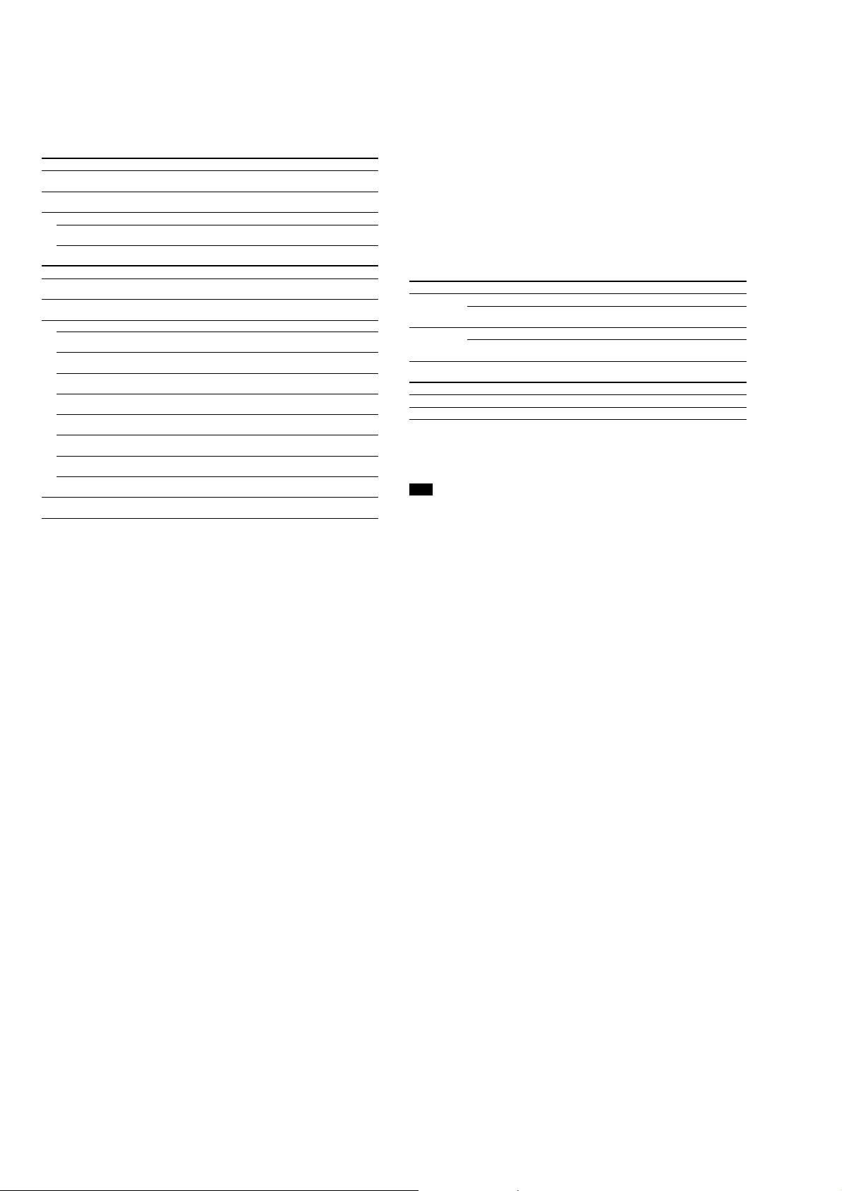
Recording and playback time
List of the recording time for each disc (Approx.)
The recording time is varied depending on disc type, disc mode, codec, and bit rate.
When using a disc in Hi-MD mode
When recording on the recorder Recording time
Codec/
Bit rate
LinearPCM/
1.4 Mbps
ATRAC
ATRAC3plus/
256 kbps
ATRAC3plus/
64 kbps
Recording mode
on the recorder
PCM 1 hour and
Hi-SP 7 hours and
Hi-LP 34 hours 10 hours and
1GB Hi-MD
disc
34 minutes
55 minutes
80-minute
standard disc
28 minutes 26 minutes 21 minutes
2 hours and
20 minutes
10 minutes
When transferring from the computer Recording time
Codec/Bit rate 1GB Hi-MD
LinearPCM/1.4 Mbps 1 hour and
ATRAC
ATRAC3plus/352 kbps 5 hours and
ATRAC3plus/256 kbps 7 hours and
ATRAC3plus/192 kbps 11 hours 3 hours and
ATRAC3plus/64 kbps 34 hours 10 hours and
ATRAC3plus/48 kbps 45 hours 13 hours and
ATRAC3/132 kbps 16 hours and
ATRAC3/105 kbps 20 hours and
ATRAC3/66 kbps 32 hours and
2)
MP3
/128 kbps 17 hours 5 hours 4 hours and
1) When transferring 4-minute tracks
2) MP3 file formats are as follows: MPEG-1 Audio Layer-3/sampling frequency 44.1 kHz/fixed bit rate.
disc
34 minutes
30 minutes
55 minutes
30 minutes
40 minutes
40 minutes
80-minute
standard disc
28 minutes 26 minutes 21 minutes
1 hour and
35 minutes
2 hours and
20 minutes
10 minutes
10 minutes
30 minutes
4 hours and
50 minutes
6 hours and
10 minutes
9 hours and
50 minutes
1)
74-minute
standard disc
2 hours and
10 minutes
9 hours and
20 minutes
74-minute
standard disc
1 hour and
30 minutes
2 hours and
10 minutes
3 hours 2 hours and
9 hours and
20 minutes
12 hours and
30 minutes
4 hours and
30 minutes
5 hours and
40 minutes
9 hours 7 hours and
30 minutes
1)
60-minute
standard disc
1 hour and
40 minutes
7 hours and
40 minutes
60-minute
standard disc
1 hour and
10 minutes
1 hour and
40 minutes
20 minutes
7 hours and
40 minutes
10 hours
3 hours and
40 minutes
4 hours and
40 minutes
20 minutes
3 hours and
30 minutes
Revolutions
Approx. 350 rpm to 3,600 rpm (CLV)
Error correction
Hi-MD: LDC (Long Distance Code)/BIS (Burst Indicator Subcode)
MD: ACIRC (Advanced Cross Interleave Reed Solomon Code)
Sampling frequency
44.1 kHz
Sampling rate converter
Optical (digital) input: 32 kHz/44.1 kHz/48 kHz
Audio formats supported by this recorder
Recording:
LinearPCM (44.1 kHz/16 bit)
ATRAC3plus (Hi-SP, Hi-LP)
ATRAC3 (LP2, LP4)
ATRAC (SP)
Playback:
LinearPCM
ATRAC3plus
ATRAC3
ATRAC
MP3 (for playback only) (MPEG-1 Audio Layer-3, sampling frequency 32/44.1/48 kHz, bit rate
32-320 kbps (fixed/variable bit rate))
ATRAC stands for Adaptive TRansform Acoustic Coding.
Modulation system
Hi-MD: 1-7RLL (Run Length Limited)/PRML (Partial Response Maximum Likelihood)
MD: EFM (Eight to Fourteen Modulation)
Frequency response (During digital and analog input)
20 to 20,000 Hz ±3 dB
Input connectors*
MIC (PLUG IN POWER): stereo mini-jack (minimum input level 0.13 mV)
LINE IN (OPT): stereo mini-jack for analog input (minimum input level 49 mV)/optical (digital)
mini-jack for optical (digital) input
Output connector
i/LINE OUT: stereo mini-jack (dedicated remote jack) / regulated output 194 mV (10 kΩ)
Maximum output (DC)
Headphones:
4.5 mW + 4.5 mW (16
5 mW + 5 mW (16
Ω) (European model)
Ω) (Other models)
Power requirements
Sony AC Power Adaptor DC 5 V AC 100 V - 240 V, 50/60 Hz
Lithium-ion rechargeable battery
LIP-4WM, 3.7 V, 370 mAh, Li-ion
Operating temperature
+5 °C (+41 °F) to +35 °C (+95 °F)
Battery operation time**
1)
Battery life
This value varies depending on how the recorder is used.
When recording/playing continuously in Hi-MD mode (Unit: approx. hours)
When Disc type LinearPCM Hi-SP Hi-LP MP3
Recording 1GB Hi-MD disc 6 9 10.5 —
Playing 1GB Hi-MD disc 10 15.5 19 16.5
60/74/80-minute
standard disc
60/74/80-minute
standard disc
5910.5 —
8 14.5 18.5 16
2)
3)
3)
When recording/playing continuously in MD mode (Unit: approx. hours)
When Disc type SP LP2 LP4
Recording 60/74/80-minute standard disc 8.5 10.5 12
Playing 60/74/80-minute standard disc 15.5 17.5 19
Measured in accordance with the JEITA (Japan Electronics and Information Technology Industries
Association) standard.
1)
Measured using a fully charged lithium-ion rechargeable battery with “EL Light” in the menu set to “Auto Off”
2)
When transferring at 128 kbps
3)
The recorder cannot record in MP3 mode. Transfer MP3 audio data using the supplied SonicStage software
Note
Repeated recharging causes the capacity of the rechargeable battery to decrease over time. As a result, the battery
life will become shorter as the battery is used. Please replace the battery when the battery life reaches about half
the time listed above.
Dimensions
Approx. 83.8 × 84.4 × 14.7 mm (w/h/d)
3
× 3 ×
/8 3/8 19/32 in.) (excluding projecting parts and controls)
(3
Mass
Approx. 96 g (3.4 oz.) (the recorder only)
Approx. 106 g (3.8 oz.) (including the rechargeable battery)
* The LINE IN (OPT) jack is used to connect either a digital (optical) cable or a line (analog)
cable.
** Measured in accordance with JEITA.
Supplied accessories
• AC power adaptor (100 V - 240 V)
• AC power cord
• USB cable
• Remote control
• Earphones
• LIP-4WM Lithium-ion rechargeable battery
• Rechargeable battery case
1)
2)
• Optical cable (for the European model)
• Carrying pouch
• Ferrite core (small size)
− Three for the European model
− Two for the North American model
• 1GB Hi-MD disc (except for the European model)
3)
• CD-ROM
(Windows: SonicStage/MD Simple Burner, Macintosh: Hi-MD Music Transfer for Mac)
• Operating Instructions (this manual)
• Operating Instructions (Hi-MD Music Transfer for Mac)
1)
The shape of the plug differs according to the region where the recorder was purchased.
Two cords with differently shaped plugs are supplied with the models for Europe, Asia and Chile.
Use the one that corresponds with the outlet configuration in the region where it is used.
2)
For the North American and Latin American models, remote with a ferrite core is supplied.
3)
Do not play a CD-ROM on an audio CD player.
For details on “Hi-MD Music Transfer for Mac”, refer to the instruction sheet supplied with this
recorder.
Design and specifications are subject to change without notice.
2

MZ-RH1
Notes on chip component replacement
• Never reuse a disconnected chip component.
• Notice that the minus side of a tantalum capacitor may be
damaged by heat.
Flexible Circuit Board Repairing
• Keep the temperature of the soldering iron around 270 ˚C
during repairing.
• Do not touch the soldering iron on the same conductor of the
circuit board (within 3 times).
• Be careful not to apply force on the conductor when soldering
or unsoldering.
CAUTION
Use of controls or adjustments or performance of procedures
other than those specified herein may result in hazardous radiation
exposure.
TABLE OF CONTENTS
1. SERVICING NOTES ............................................... 4
2. GENERAL................................................................... 5
3. DISASSEMBLY
3-1. Disassembly Flow ........................................................... 6
3-2. Panel (Lower) Section ..................................................... 6
3-3. Cabinet (Front) Section ................................................... 7
3-4. MAIN Board.................................................................... 7
3-5. Panel (Upper) Assy.......................................................... 8
3-6. Mechanism Deck (MT-MZRH1-181) ............................. 8
3-7. Torsion Spring (Pop Up L),
Torsion Spring (Pop Up R) .............................................. 9
3-8. Gear (SA), Gear (SB) ...................................................... 9
3-9. OP Service Assy (ABX-U2)............................................ 10
3-10. DC Motor SSM18D/C-NP (Spindle) (M701),
DC Motor (Sled) (M702),
DC Motor Unit (Over Write Head Up/Down) (M703) ... 10
3-11. Holder Assy ..................................................................... 11
3-12. Position of Ferrite Core ................................................... 11
4. TEST MODE.............................................................. 12
5. ELECTRICAL ADJUSTMENTS......................... 16
SAFETY-RELATED COMPONENT WARNING!!
COMPONENTS IDENTIFIED BY MARK 0 OR DOTTED LINE
WITH MARK 0 ON THE SCHEMATIC DIAGRAMS AND IN
THE PARTS LIST ARE CRITICAL TO SAFE OPERATION.
REPLACE THESE COMPONENTS WITH SONY PARTS WHOSE
PART NUMBERS APPEAR AS SHOWN IN THIS MANUAL OR
IN SUPPLEMENTS PUBLISHED BY SONY.
6. DIAGRAMS
6-1. Block Diagram – SERVO Section – ................................ 21
6-2. Block Diagram – AUDIO Section – ................................ 22
6-3. Block Diagram – POWER SUPPLY Section – ............... 23
6-4. Schematic Diagram – MAIN Section (1/7) – .................. 25
6-5. Schematic Diagram – MAIN Section (2/7) – .................. 26
6-6. Schematic Diagram – MAIN Section (3/7) – .................. 27
6-7. Schematic Diagram – MAIN Section (4/7) – .................. 28
6-8. Schematic Diagram – MAIN Section (5/7) – .................. 29
6-9. Schematic Diagram – MAIN Section (6/7) – .................. 30
6-10. Schematic Diagram – MAIN Section (7/7) – .................. 31
6-11. Printed Wiring Board
– MAIN Board (Component Side) – ............................... 32
6-12. Printed Wiring Board
– MAIN Board (Conductor Side) – ................................. 33
6-13. Printed Wiring Board – OLED Board – .......................... 34
6-14. Schematic Diagram – OLED Board – ............................. 35
7. EXPLODED VIEWS
7-1. Panel (Upper) Section ..................................................... 52
7-2. Cabinet (Front) Section ................................................... 53
7-3. Lower Panel Section........................................................ 54
7-4. Set Chassis Section.......................................................... 55
7-5. MAIN Board Section....................................................... 56
7-6. Mechanism Deck Section (MT-MZRH1-181) ................ 57
8. ELECTRICAL PARTS LIST................................ 58
ATTENTION AU COMPOSANT AYANT RAPPORT
À LA SÉCURITÉ!
LES COMPOSANTS IDENTIFIÉS P AR UNE MARQ UE 0 SUR
LES DIAGRAMMES SCHÉMATIQUES ET LA LISTE DES
PIÈCES SONT CRITIQUES POUR LA SÉCURITÉ DE
FONCTIONNEMENT. NE REMPLACER CES COM- POSANTS
QUE PAR DES PIÈCES SONY DONT LES NUMÉROS SONT
DONNÉS DANS CE MANUEL OU D ANS LES SUPPLÉMENTS
PUBLIÉS PAR SONY.
3
MZ-RH1
System requirements
The following system environment is required in order to use the SonicStage/MD Simple Burner
software.
Computer IBM PC/AT or Compatible
• CPU: Pentium III 450 MHz or higher
• Hard disk drive space: 200 MB or more (1.5 GB or more is recommended)
(The amount space will vary according to Windows version and the number
of music files stored on the hard disk.)
• RAM: 128 MB or more
Others • CD drive (capable of digital playback by WDM) (A CD-R/RW
drive is necessary for CD writing)
• Sound Board
• USB port
Operating
System
Factory installed:
Windows XP Media Center Edition 2005/Windows XP Media Center Edition
2004/Windows XP Media Center Edition/Windows XP Professional/Windows
XP Home Edition/Windows 2000 Professional (Service Pack 3 or later)/
Windows Millennium Edition/Windows 98 Second Edition
Display High Color (16 bit) or higher, 800
better is recommended)
Others • Internet access for online registration and CDDB use
• Internet access and Microsoft Internet Explorer (version 5.5 or higher) for use
of EMD services
• Windows Media Player (version 7.0 or higher) installed for playing WMA
files
This software is not supported by operating systems other than those listed above, custom-built
PCs, operating systems that are upgrades from the original manufacturer-installed system, multiboot environments, multi-monitor environments, or Macintosh computers.
Notes
• We do not ensure trouble-free operation on all computers that satisfy the system requirements.
• The NTFS format of Windows XP/Windows 2000 Professional can be used only with the standard (factory)
settings.
• We do not ensure trouble-free operation of the system suspend, sleep, or hibernation function on all computers.
SECTION 1
SERVICING NOTES
NOTES ON HANDLING THE OPTICAL PICK-UP
BLOCK OR BASE UNIT
The laser diode in the optical pick-up block may suffer electrostatic
break-down because of the potential difference generated by the
charged electrostatic load, etc. on clothing and the human body.
During repair, pay attention to electrostatic break-down and also
use the procedure in the printed matter which is included in the
repair parts.
The flexible board is easily damaged and should be handled with
care.
NOTES ON LASER DIODE EMISSION CHECK
The laser beam on this model is concentrated so as to be focused on
the disc reflective surface by the objective lens in the optical pickup block. Therefore, when checking the laser diode emission,
observe from more than 30 cm away from the objective lens.
UNLEADED SOLDER
Boards requiring use of unleaded solder are printed with the leadfree mark (LF) indicating the solder contains no lead.
(Caution: Some printed circuit boards may not come printed with
the lead free mark due to their particular size)
: LEAD FREE MARK
Unleaded solder has the following characteristics.
• Unleaded solder melts at a temperature about 40 °C higher
than ordinary solder.
Ordinary soldering irons can be used but the iron tip has to be
applied to the solder joint for a slightly longer time.
Soldering irons using a temperature regulator should be set to
about 350 °C.
Caution: The printed pattern (copper foil) may peel away if
the heated tip is applied for too long, so be careful!
• Strong viscosity
Unleaded solder is more viscou-s (sticky, less prone to flow)
than ordinary solder so use caution not to let solder bridges
occur such as on IC pins, etc.
• Usable with ordinary solder
It is best to use only unleaded solder but unleaded solder may
also be added to ordinary solder.
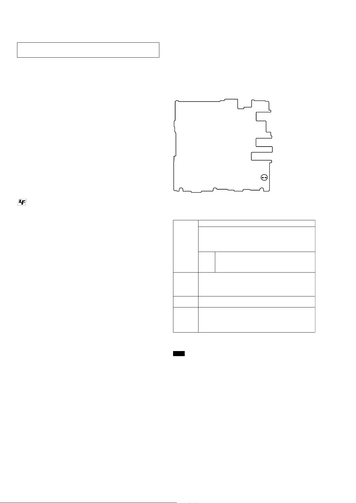
OPERATION CHECK WHEN THE MAIN BOARD IS
REMOVED
In making an operation check with the MAIN board removed from
the set, short the SL463 of the MAIN board with the solder before
starting the operation check.
Note: Be sure to remove the solder used for shortcircuit after the repaire
completed.
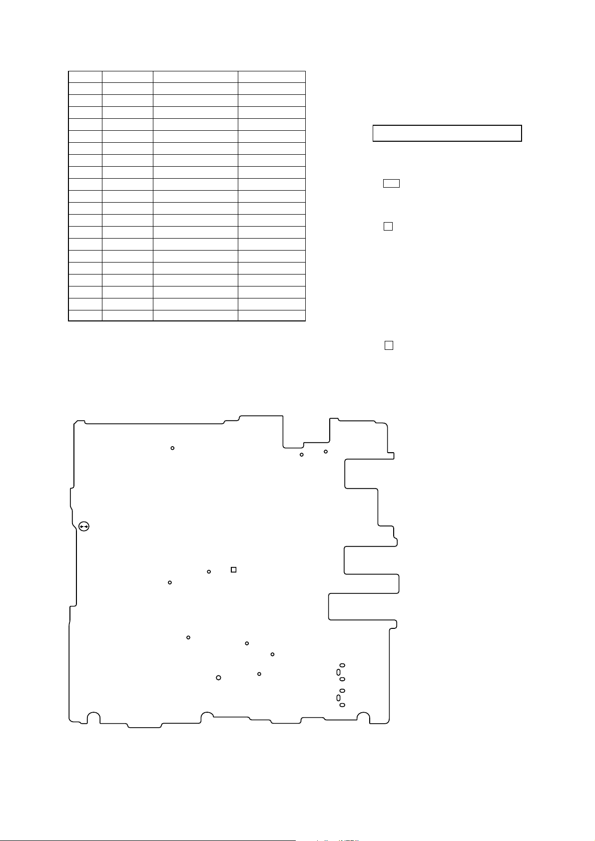
– MAIN Board (Conductor Side) –
SL463
NOTES ON REPLACEMENT OF CSP (CHIP SIZE
PACKAGE) IC
Replacement of IC401, IC501, IC601 and IC701 on the MAIN board
used in this set requires a special tool.
NOTES ON REPLACEMENT OF IC801 ON THE MAIN
BOARD
IC801 on the MAIN board can not be exchanged alone. When IC801
on the MAIN board is damaged, exchange the complete MAIN
board.
NOTES ON REPLACEMENT OF IC1 AND S8 ON
THE OLED BOARD
IC1 and S8 on the OLED board can not be exchanged alone. When
IC1 and S8 on the OLED board are damaged, exchange the complete
OLED board.
4
SECTION 2
GENERAL
MZ-RH1
This section is extracted from
instruction manual.
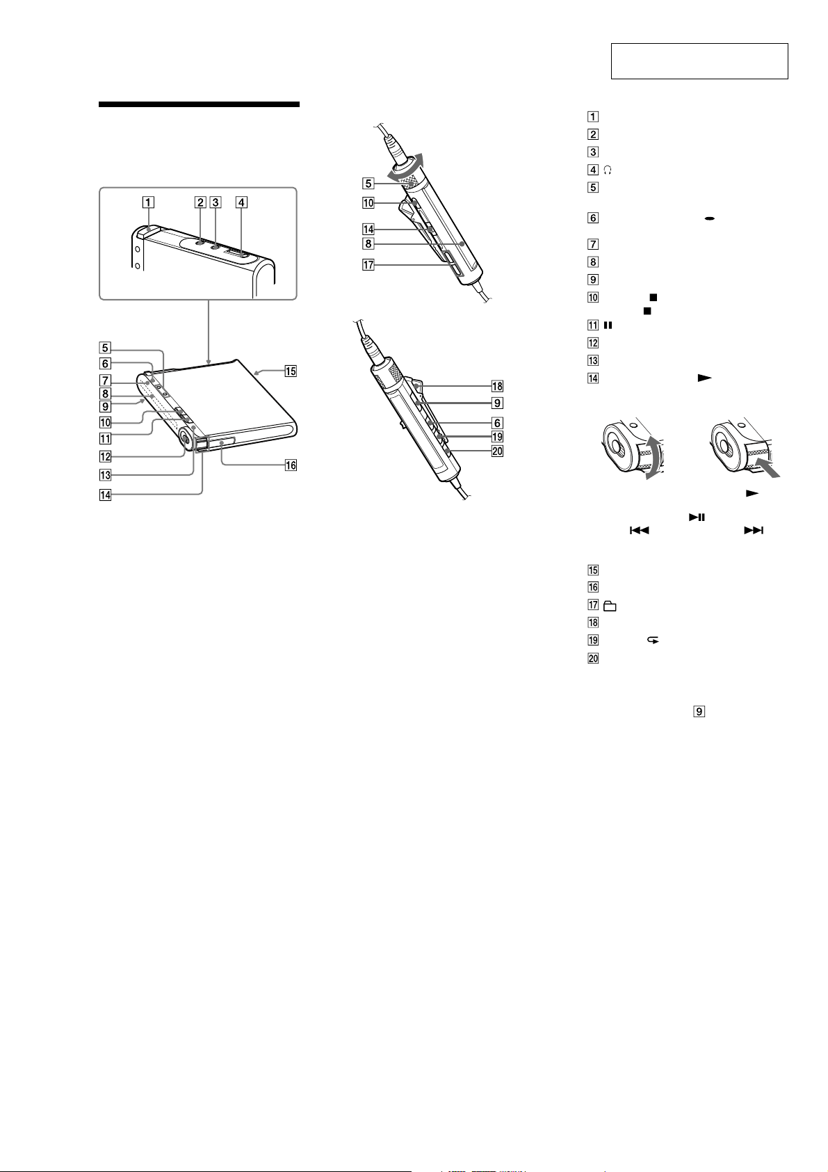
Guide to Parts and
Controls
Recorder
Remote
OPEN button
LINE IN (OPT) jack
MIC (PLUG IN POWER)* jack
(earphones)/LINE OUT jack
Recorder: VOL +*/− buttons
Remote: VOL +/− control
Recorder: • DISPLAY/ MENU button
Remote: DISPLAY button
Operation lamp
Display window
HOLD switch
Recorder: (stop) · CANCEL button
Remote:
(pause) button
REC switch
T MARK button
Recorder: Jog lever ( (play)/ENT*,
FF (AMS, fast forward), FR (AMS, fast
rewind))
Move (FF/FR)
(stop) button
FF
FR
Push (
/ENT)
Remote: Jog lever ( (play, pause)/
ENT,
(AMS, fast forward))
USB cable connecting jack
Battery compartment
(group) +/− button
Clip
P MODE/ (repeat) button
SOUND button
* There is a tactile dot.
Locking the controls (HOLD)
Slide the HOLD switch on the recorder or
on the remote in the direction of the arrow.
You can prevent accidental button presses
while carrying the recorder by locking the
controls. You can use the HOLD function for
the recorder and the remote separately. For
example, even if the HOLD function on the
recorder is activated, you can operate the
recorder by using the remote unless you set
HOLD on the remote to on, too.
(AMS, fast rewind),
5
MZ-RH1
s
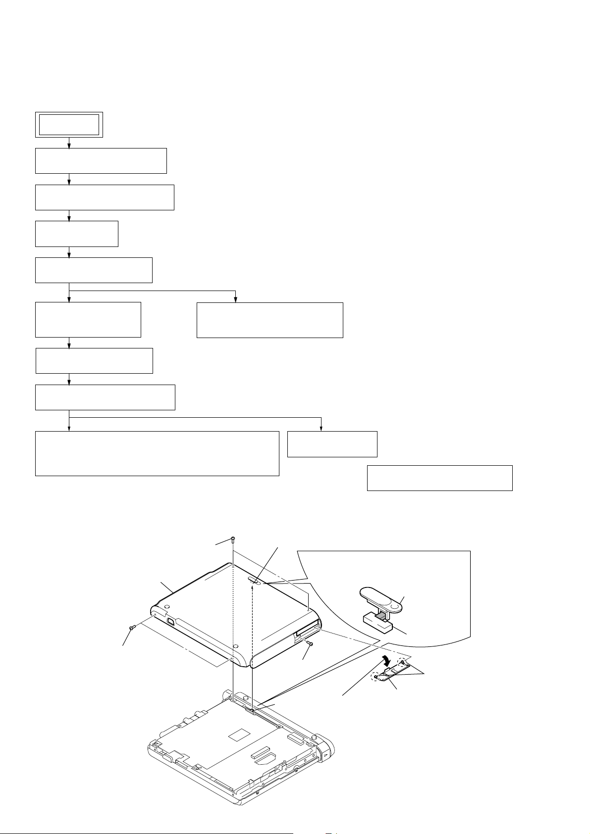
• This set can be disassembled in the order shown below.
3-1. DISASSEMBLY FLOW
SET
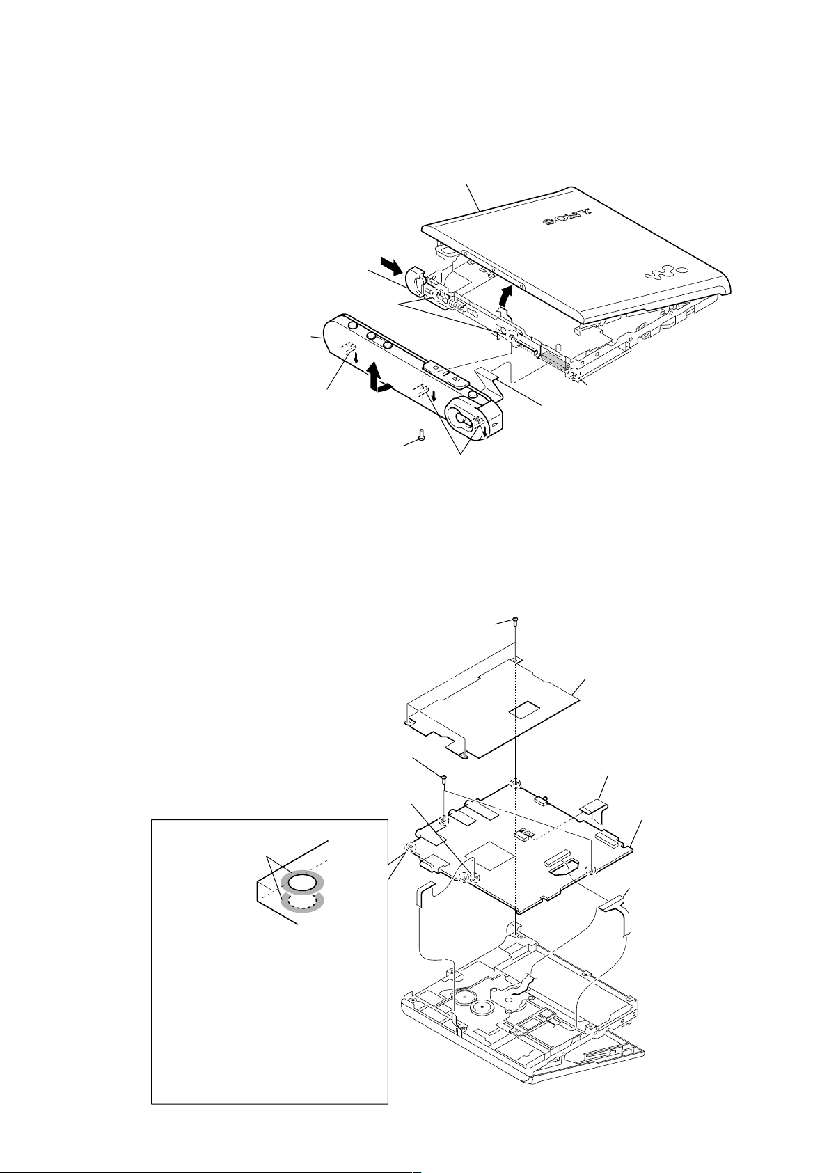
3-2. PANEL (LOWER) SECTION
(Page 6)
3-3. CABINET (FRONT) SECTION
(Page 7)
3-4. MAIN BOARD
(Page 7)
3-5. PANEL (UPPER) ASSY
(Page 8)
SECTION 3
DISASSEMBLY
3-6. MECHANISM DECK
(MT-MZRH1-181)
(Page 8)
3-8. GEAR (SA), GEAR (SB)
(Page 9)
3-9. OP SERVICE ASSY (ABX-U2)
(Page 10)
3-10. DC MOTOR SSM18D/C-NP (SPINDLE) (M701),
DC MOTOR (SLED) (M702),
DC MOTOR UNIT (OVER WRITE HEAD UP/DOWN) (M703)
(Page 10)
Note: Follow the disassembly procedure in the numerical order given.
3-7. TORSION SPRING (POP UP L),
TORSION SPRING (POP UP R)
(Page 9)
3-2. PANEL (LOWER) SECTION
5
two screws
(M1.4)
6
panel (lower) section
3-11. HOLDER ASSY
(Page 11)
3-12. POSITION OF FERRITE CORE
(Page 11)
knob (hold)
Note: On installation of panel (lower)
section, adjust the position of
switch (S464) and knob (hold).
knob (hold)
S464
5
two screws
(M1.4)
4
screw
(M1.4)
S464
1
Open the
battery case lid.
2
3
battery case lid
two bosse
6
3-3. CABINET (FRONT) SECTION
d
1
Push the knob (open) in the direction
of arrow A and open the panel (upper)
section.
convex part of screw hole
5
Remove the cabinet (front)
section in the direction of
arrow B.
MZ-RH1
Ver. 1.1
panel (upper) assy
A
4
Remove from the convex
part of the screw hole.
3-4. MAIN BOARD
B
3
screw (M1.4)
1
6
two screws (M1.4)
3
Remove two solders of the
flexible board (over write head
(HR601)).
4
Remove from the convex part of the screw hole.
three screws (M1.4)
convex part of screw hole
2
flexible board
(18core) (CN471)
2
shield assy
5
motor flexible
board (CN701)
7
MAIN board
The screw fixing areas
is cleaned.
Note: When mounting the MAIN Board, clean
the screw fixing areas (5 places
sides) of the MAIN Board with alcohol
(ethanol), and then tighten the screws.
Also, when tightening the screws, use
a torque driver and tighten them to a
torque range of 0.06 – 0.08N.
(Excessive torque over 0.1N could
bend the chassis.)
(Without cleaning, or with the screws
tightened loosely, the set may not start
when the USB cable is inserted.)
×
both
4
OP flexible boar
(CN501)
7

MZ-RH1
)
3-5. PANEL (UPPER) ASSY
1
two screws (M1.4)
2
panel (upper) assy
1
two screws (M1.4)
3-6. MECHANISM DECK (MT-MZRH1-181)
3
mechanism deck
(MT-MZRH1-181)
2
two step screws (MD
1
case (batt)
8
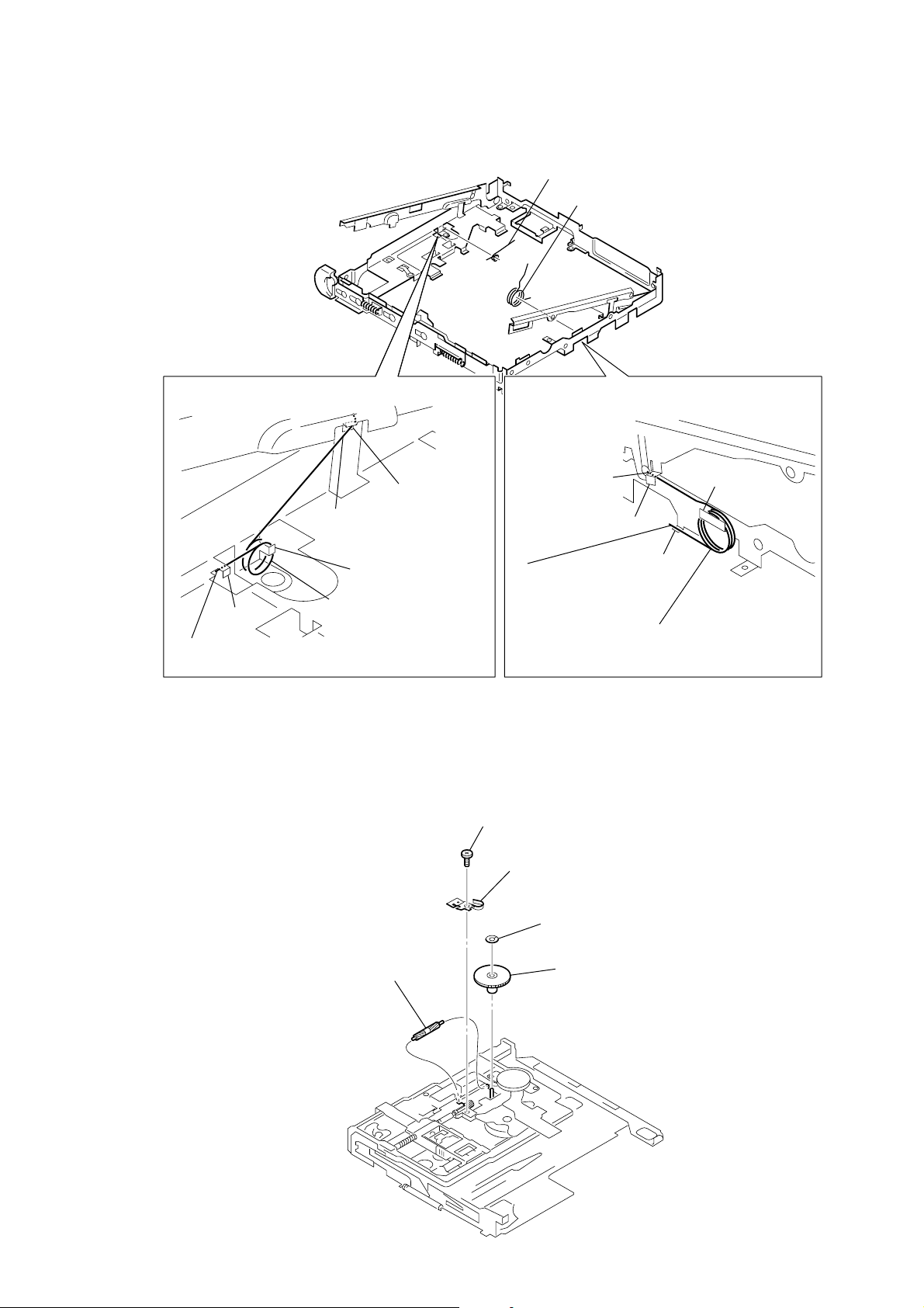
3-7. TORSION SPRING (POP UP L), TORSION SPRING (POP UP R)
1
torsion spring (POP UP L)
2
torsion spring (POP UP R)
MZ-RH1
HOW T O INSTALL THE
TORSION SPRING (POP UP L)
hook
2
Engage the end
torsion spring (POP UP L) with the hook.
3-8. GEAR (SA), GEAR (SB)
hook
3
Engage the end
torsion spring (POP UP L)
with the hook.
hook
1
Engage the coil
torsion spring (POP UP L)
with the hook.
HOW T O INSTALL THE
TORSION SPRING (POP UP R)
3
Engage the end
torsion spring
(POP UP R)
with the hook.
hook
2
Engage the end
torsion spring (POP UP R)
with the hook.
1
self tap screw
hook
hook
1
Engage the coil
torsion spring (POP UP R)
with the hook.
5
gear (SB)
2
thrust retainer spring
3
washer (0.8-2.5)
4
gear (SA)
9
MZ-RH1
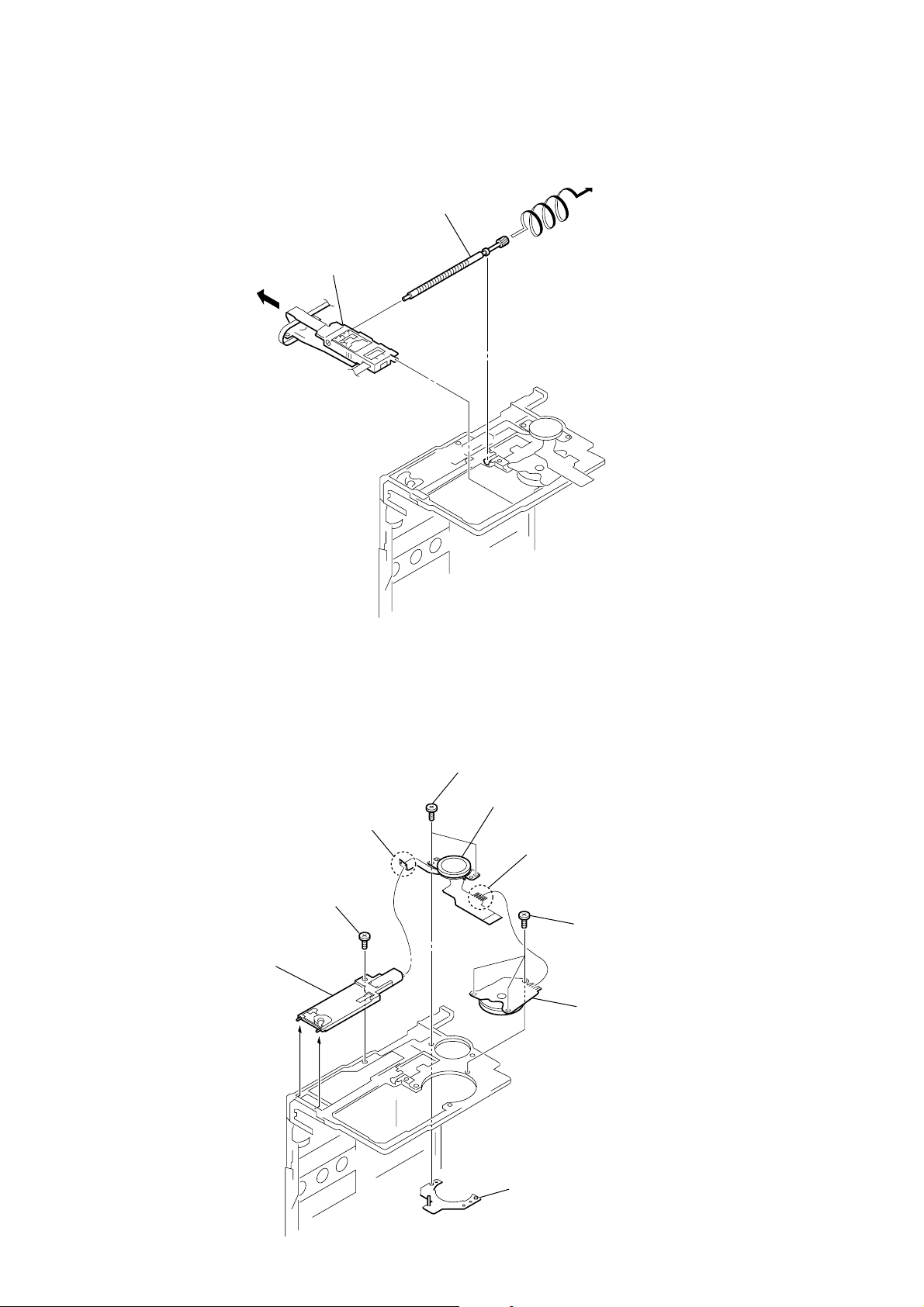
3-9. OP SERVICE ASSY (ABX-U2)
1
Lead screw block assy is turned
and it removes from OP service assy.
2
OP service assy (ABX-U2)
3-10. DC MOTOR SSM18D/C-NP (SPINDLE) (M701), DC MOTOR (SLED) (M702) ,
DC MOTOR UNIT (OVER WRITE HEAD UP/DOWN) (M703)
3
two screws (M1.4)
4
DC motor (sled)
2
Remove two solders of flexible board.
9
DC motor unit
(over write head up/down)
(M703)
8
self tap screw
(M702)
1
Remove four solders of flexible board.
6
three self tap screws
7
DC motor SSM18D/C-NP
(spindle) (M701)
10
5
motor base assy
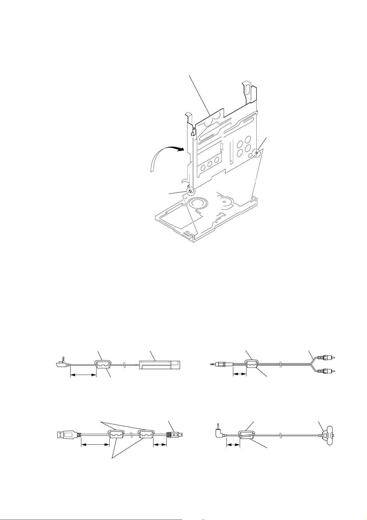
3-11. HOLDER ASSY
e
1
Open the holder assy
to the direction of the arrow
A
holder assy
3
A
.
2
MZ-RH1
boss
3-12. POSITION OF FERRITE CORE
– REMOTE CONTROL UNIT (SUPPLIED) –
A cable is rolled once. remote control unit
2
boss
– LINE CABLE (OPTION) –
A cable is rolled once. line cable of option
4cm
– USB CABLE (SUPPLIED) –
A cable is rolled once.
clamp filter (ferrite core)
(Part No. 1-400-877-11)
clamp filter (ferrite core)
(Part No. 1-400-878-11)
USB cable
1cm4cm
of option
1cm
– STEREO MICROPHONE (OPTION) –
A cable is rolled twice without twisting it.
1cm
clamp filter (ferrite core)
(Part No. 1-500-484-21)
clamp filter (ferrite core)
(Part No. 1-400-877-11)
stereo microphon
11
MZ-RH1
SECTION 4
TEST MODE
OUTLINE
Operation in the test mode is performed with the set. A k e y having
no particular description in the text, indicates a set key. Also, For
the display, the EL display on the set is shown.
1. OPERATION IN SETTING THE TEST MODE
• When the test mode becomes active, first the Display Check
mode is selected.
• Other mode can be selected from the Display Check mode.
• When the test mode is set, the EL repeats the following display .
• When the x key is pressed and hold down, the display at that
time is held so that display can be checked.
Display check mode:
All lit
All off
Ver 1.000 BEr******
Microcomputer
version display
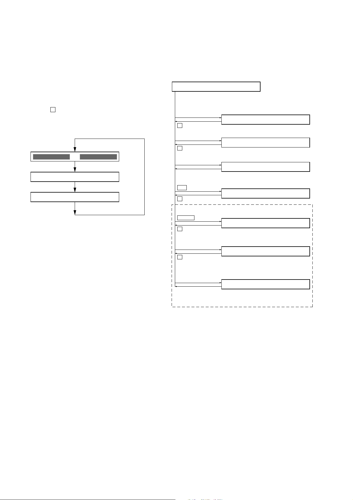
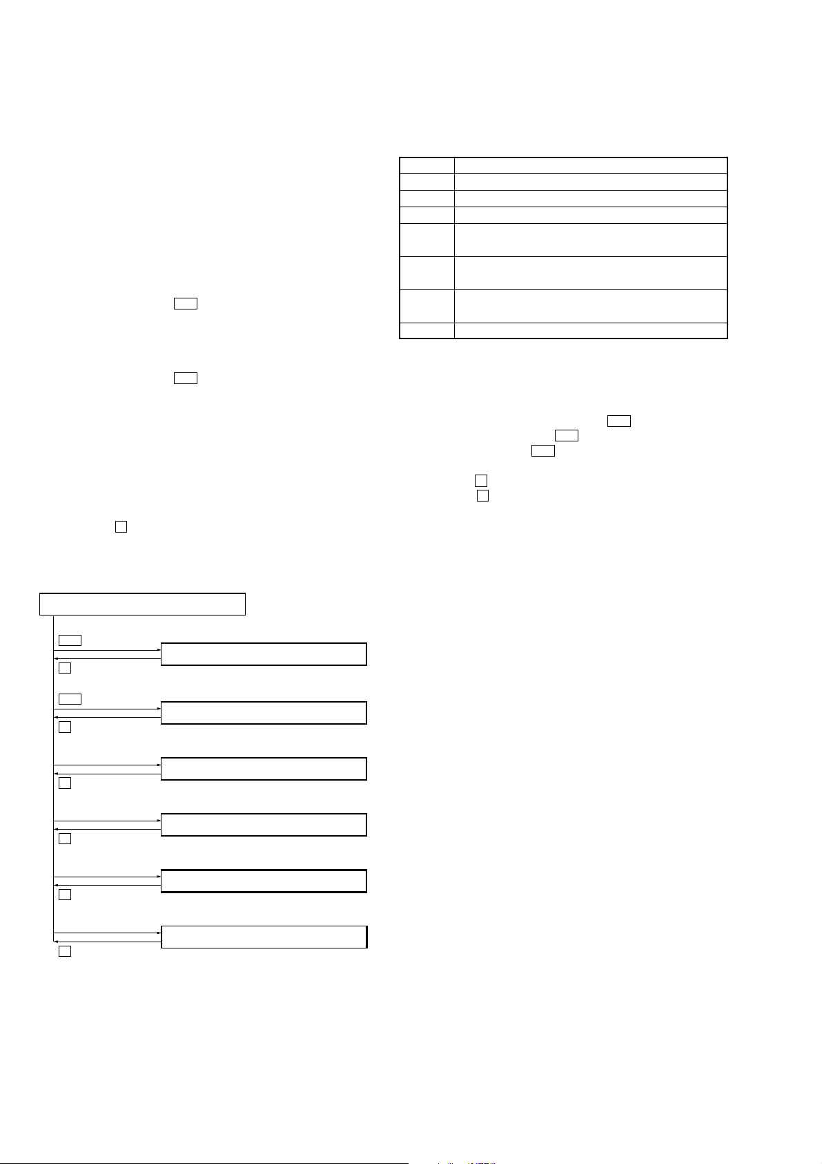
2. CONFIGURATION OF THE TEST MODE
It shifts from the display check mode to each mode as shown in the
figure below.
Flow of the test mode:
Display Check Mode
Ver 1.000 BEr******
[VOL +]
Version display
→
All off → Version display...
key
→
All lit
Manual Mode
0000 Manual
key
x
[VOL --]
key
key
x
[DISPLAY/MENU]
Open the
upper panel
>
key
key
x
N/ENT
key
Overall Adjustment Mode
0000 AdjF**
Key Check Mode
key
0100 10
Self-Diagnosis Result Display Mode
0000 1 0000
Sound Skip Check Result
Display Mode (Play)
0000 P00r00
key
x
Sound Skip Check Result
[REC/T MARK]
key
Display Mode (REC)
0000 p00R00
key
x
[DISPLAY/MENU]
(press a few
seconds)
key
Key Count Mode
0000
Remote commander
[DISPLAY]
(press a few seconds)
(Not used in servicing. Return to the display check mode when
entering by mistake)
key
12
MZ-RH1
•
Address & Adjusted Value Display
item number
item title
adjusted value
•
Jitter Value & Adjusted Value Display
•
Block/Bite Error Value & Adjusted Value Display
•
ADIP Error Value & Adjusted Value Display
•
Focus Drive Value & Adjusted Value Display
•
Item Title Display
•
Bite Error LPF Value & Adjusted Value Display *1)
•
CEMAX Value & Adjusted Value Display *1)
XXXX ******##
item number
address
adjusted value
XXXX ***S##
item number
jitter value
adjusted value
XXXX ***J##
item number
block/bite error value
adjusted value
XXXX ***B##
item number
bite error LPF value
adjusted value
XXXX ***B##
item number
CEMAX value
adjusted value
XXXX ***B##
item number
ADIP error value
adjusted value
XXXX ***B##
item number
focus drive voltage value
adjusted value
XXXX ***B##
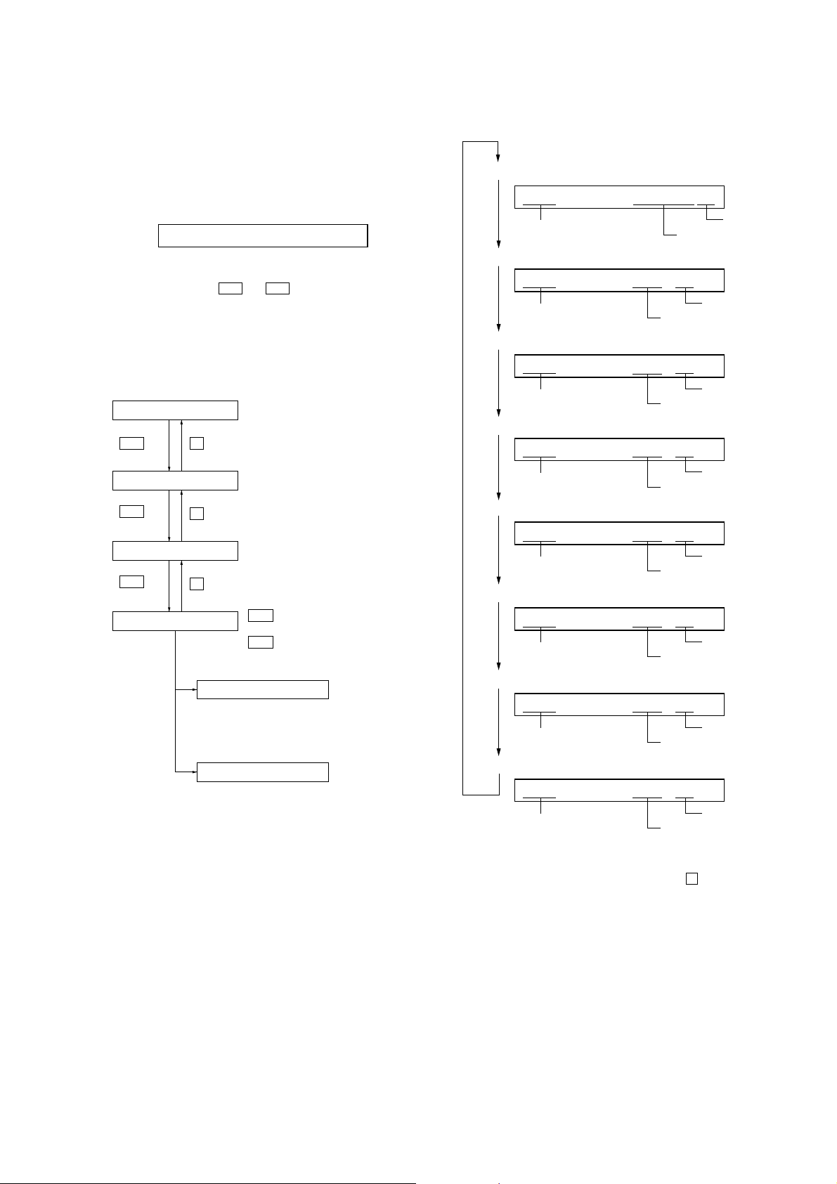
3. MANUAL MODE
This is mode to adjust or check the operation of the set by function.
Operation of The Manual Mode
1. Enter the test mode (Display Check mode).
2. Press the [VOL+] key to activate the Manual mode where the
EL displays as shown below.
0000 Manual
3. During Manual mode, the optical pick-up moves outward or
inward while the > or . key is pressed for several
seconds respectively.
4. Each test item is assigned with a four-digit item number; 1000th
place is a top item, 100th place is a major item, 10th place is a
medium item, and unit place is a minor item.
Flow of manual mode operation:
[VOL +]
Top item switching
>
key
Major item switching
>
key
key
x
key
x
key: 1000th place of item
number increase.
[VOL --]
key: 1000th place of item
number decrease.
[VOL +]
key: 100th place of item
number increase.
[VOL --]
key: 100th place of item
number decrease.
5. The display changes a shown below each time the
[DISPLAY/MENU] key is pressed.
Medium item switching
>
key
Minor item switching
key
x
Adjusted value variation
[VOL +]
[VOL --]
>
.
[VOL +]
key: Increases the adjusted
[VOL --]
key: Decreases the adjusted
Adjusted value write
[ ]
key: Adjusted value is written.
X
key: 10th place of item
number increase.
key: 10th place of item
number decrease.
key: 1st place of item
number increase.
key: 1st place of item
number decrease.
value.
value.
*1) It is skipped excluding the item number 5000 less than 8000.
6. To release the Manual mode, press the x key to return to the
Display Check mode.
13
MZ-RH1
e
4. OVERALL ADJUSTMENT MODE
Operation of The Overall Adjustment Mode
1. Enter the test mode (Display Check mode).
2. Press the [VOL--] key to activate the Overall Adjustment mode
where the EL displays as shown below.
0000 AdjF**
“**”:
If “DF” or “FF” is displayed, it mean that completed the servo
overall adjustment.
3. To release the Overall Adjustment mode, press the x key and
return to the Display Check mode.
5. SELF-DIAGNOSIS RESULT DISPLAY MODE
This set uses the self-diagnostic function system in which if an error
occurred during the recording or playing, the mechanism control
block and the power supply control block in the microcomputer
detect it and record its cause as history in the nonvolatile memory.
By checking this history in the test mode, you can analyze a fault
and determine its location.
Total recording time is recorded as a guideline of how long the
optical pick-up has been used, and by comparing it with the total
recording time at the time when an error occurred in the selfdiagnosis result display mode, you can determine when the error
occurred.
Clear the total recording time, if the optical pick-up was replaced.
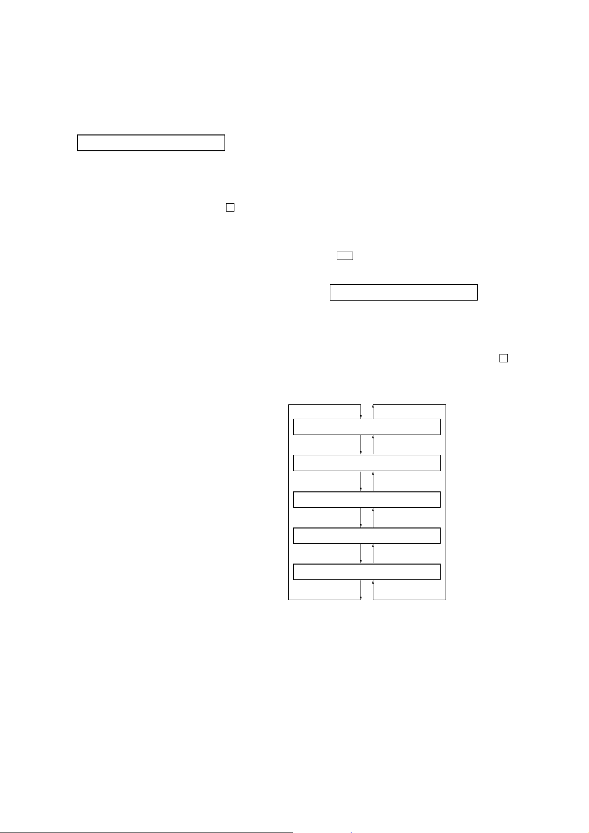
5-1. Operation of The Self-Diagnosis Result Display
Mode
1. Enter the test mode (Display Check mode).
2. Press the > key to activate the Self-Diagnosis Result Display
mode where the LCD displays as shown below.
**** $$####
“****”: Error display code
“$$”: Error revision history code
“####”: Addition information when error occurs
3. To release the Self-Diagnosis Result Display mode, press the x key
and return to the Display Check mode.
Flow of Self-diagnosis Result Display mode operation:
**** 1 ####
[VOL +]
key
[VOL --]
**** N ####
[VOL +]
key
[VOL --]
**** N1####
[VOL +]
key
[VOL --]
**** N2####
[VOL +]
key
[VOL --]
**** R_####
[VOL +]
key
[VOL --]
key
key
key
key
key
The first error
The last error
One error before
the last
Two error before
the last
Total recording tim
14

MZ-RH1
5-2. Error Code of The Self-Diagnosis Result Display
Mode
Error display code Description
0000 No error
0001 Attempt to access an abnormal address
0002 High temperature detected
0003 Focus error (no change)
0004 Abnormal rotation of disc
0005 Fault of disc discriminate
0006 Error of access loop (no change)
0007 Error of access loop (with change)
0008 Could not read address
0009 Focus error (with change)
0012 Could not read data with SYNC
0013 TOC address data error
0032 Focus error, ABCD offset error
0033 Tracking error, offset error
0034 X1 tracking error, Tracking error, offset error
Error display code Addition information when error occurs
0000 0000
0001 Illegal cluster specified when error occurs
0002 to 0034 Total recording time when error occurs
6. KEY CHECK MODE
This mode is used for key check.
Operation of The Key Check Mode
1. Enter the test mode (Display Check mode).
2. Press the [DISPLAY/MENU] key to activate the Key Check mode
where the LCD displays as shown below.
0100 $$$$$$ # #
“$$$$$$”:Pressed key name.
When remote commander key is pressed, display becomes
as “r$$$$$”.
“##”:Key voltage of remote commander. (Hexadecimal number)
3. To release the Key Check mode, open the upper panel and
return to the Display check mode.
5-3. Clear The Total Recording Time
After replacing the optical pick-up, clear the total recording time.
1. Enter the test mode (Display Check mode).
2. Press the > key to activate the Self-Diagnosis Result Display
mode.
3. Press the [VOL--] key once to display the total recording time
indication.
4. Press the X key and display “ClrOK?”.
5. Press the X key again to display “RecT 0” and clear the total
recording time.
15
MZ-RH1
SECTION 5
ELECTRICAL ADJUSTMENTS
1. PRECAUTIONS FOR ADJUSTMENT
1. Adjustment must be done in the test mode only. After adjusting,
release the test mode. A key having no particular description
in the text, indicates a set key. Also, for the display, the EL
display on the set is shown.
2. Use the following tools and measuring instruments.
• Digital voltmeter
• Regulated dc power supply (two sets)
• Laser power meter
• CD adjustment disc TDYS-1 (Part No. : 4-963-646-01)
• MD1/HiMD1 hybrid adjustment disc MDW-74/GA2
(Part No.: J-2503-022-A)
• Hi-MD3 adjustment disc HMD1GSDJ
(Part No. : 8-892-388-38) *1
• USB cable, AC power adapter and AC cord in accessories
*1) Hi-MD3 adjustment disc (HMD1GSDJ) is consumable.
Therefore if it is used 400 times, exchange it for a new.
2. ADJUSTMENT SEQUENCE
Adjustment must be done with the following order.
Adjustment order:
1. Entering the test mode
Note: Enter the test mode with a key.
2. Initialize the adjustment value
3. Power supply voltage adjustment
4. Charge function check
5. Laser power check
6. Setting the adjustment values
7. Servo Overall adjustment
8. Resume clear
9. Releasing the test mode
3. ADJUSTMENT OF THE EACH ITEM
3-1. Initialize The Adjustment Value
Procedure:
1. In the test mode (Display Check mode), press the [VOL--] key
to enter the Overall adjustment mode.
2. Press the [T MARK] key and display “1911 ResOK?”.
3. Press the X key to display “1911 Reset!” and initialize the
adjustment values.
4. Press the x key and back to Display Check mode.
3-2. Power Supply Voltage Adjustment
Adjustment must be done with the following order.
3-2-1. Setting
Procedure:
1. Apply the voltage of 3.7 V to W401 (BATT+) and W402
(BATT–), and enter the test mode (Display Check mode).
2. Press the [VOL+] key to enter the Manual mode.
3. Press the [VOL+] key twice to display as follows.
2000 POWER
4. Press the > key once, press the [VOL+] key once, and press
the > key once again to display as follows.
2210 PwrAdj
5. Repeat the next procedures (3-2-2. PwrAdj Adjustments), and
adjust all contents of “table 3-2-1. PwrAdj Specifications”.
3-2-2. PwrAdj adjustments
Repeat the following procedures and adjust all contents of “table 32-1. PwrAdj Specifications”.
Example Display (Item No. 2211)
2211 VC1 **
adjustment value (hexadecimal)
Procedure:
1. Connect the digital voltmeter to measuring point (refer to the
following table 3-2-1) and CL965 (GND).
2. Press the > key to change the item number to 2211.
3. Adjust with [VOL+]/[VOL--] keys so that the value of digital
voltmeter becomes specification value.
4. Press the X key to write the adjusted value. (Shifts to the
next item automatically)
5. Repeat adjustment from step 3 until item number 2234.
16
MZ-RH1
Item No. Display Specification value Measuring point
2211 VC1 ** 2.05V + 0.02V TP8065
2212 VC1H N ** 2.25V ± 0.01V TP8065
2213 VC2L ** 1.50V + 0.01V CL8001
2214 VC2H ** 1.50V + 0.01V CL8001
2217 REG1 L ** 3.02V ± 0.02V CL954
2218 REG1 H ** 3.02V ± 0.02V CL954
2219 REG2 1 ** 2.275V ± 0.01V CL951
2221 REG2 2 ** 2.480V ± 0.01V CL951
2222 REG2 3 ** 2.740V ± 0.01V CL951
2223 REG2 4 ** 2.985V ± 0.01V CL951
2224 REG3 ** 2.52V ± 0.02V CL947
2225 VREC 1 ** 0.75V ± 0.02V CL601
2226 VREC 2 ** 0.80V ± 0.02V CL601
2227 VREC 3 ** 1.52V ± 0.02V CL601
2228 VREC 4 ** 2.17V ± 0.02V CL512
2229 VREC 5 ** 2.78V ± 0.02V CL512
2231 VREC 6 ** 0.75V ± 0.02V CL601
2232 VREC 7 ** 0.90V ± 0.02V CL601
2233 VREC 8 ** 2.10V ± 0.02V CL601
2234 VREC 9 ** 2.70V ± 0.02V CL601
Note1: “**” is adjustment value (hexadecimal number).
Note2: Ground point of all measuring points is CL965.
Note3: Item number 2228, 2229 are adjusted with the mechanism deck
connected.
Table 3-2-1. PwrAdj Specifications
3-2-3. VBsAdj adjustments
Procedure:
1. In the “3-2-2. PwrAdj Adjustments” completed status, display
as follows.
2240 VBsAdj
2. Apply the voltage of 5 V to CL441 (VBUS 5V) and CL445
(VBUS GND).
3. Press the > key to change the item number to 2241.
4. Adjust with [VOL+]/[VOL--] keys so that the value of digital
voltmeter becomes specification value. (Refer to “table 3-2-
2. VBsAdj Specifications”)
5. Press the X key to write the adjusted value.
6. Repeat adjustments to item number 2242 at the same manner
as step 4 to step 5.
7. Select the item number 2244, and turn off the power supply of
applying to W401 (BATT+) and W402 (BATT–).
8. Repeat adjustments to item number 2244, 2245 and 2246 at
the same manner as step 4 to step 5.
9. Apply the voltage of 3.7 V to W401 (BATT+) and W402
(BATT–) again.
10. Turn off the voltage of 5 V to CL441 (VB US 5V) and CL445
(VBUS GND).
11. Press the x key three times and back to the Display Check
mode.
Adjustment Location:
– MAIN Board (Conductor Side) –
CL601
SL802
CL8001
CL512
CL947
CL965
CL445
CL441
TP8065
CL964
CL951
W402
CL954
W401
17

MZ-RH1
)
Item No. Display Specification value Measuring point
2241 REG4 ** 1.13 V ± 0.01 V CL8001
2242 REG5 ** 2.05 V + 0.02 V TP8065
2244 DDC5 N ** 4.20 V – 0.02 V CL964
2245 DDC5 C ** 4.45 V – 0.02 V CL964
2246 DDC5 L ** 4.20 V – 0.02 V CL964
Note1: “**” is adjustment value (hexadecimal number).
Note2: Ground point of all adjustment points is CL965.
Note3: Refer to page 17 for adjustment location.
Table 3-2-2. VBsAdj Specifications
3-3. Charge Function Check
Note1: When perform this check, don’t apply a voltage to battery terminals.
Note2: Be sure to turn the power off when connecting the resistor. Doing
so with the power supply connected causes a trouble.
Procedure:
1. Connect the resistor (10Ω, more than 3W) to battery terminals.
2. Connect the USB cable, AC adapter and A C cord, and turn the
power on.
3. Enter the test mode (Display Check mode).
4. Press the [VOL+] key to enter the Manual mode.
5. Press the [VOL+] key twice, press the > key once, press the
[VOL+] key once.
6. Press the > key once, press the [VOL+] key twice to display
as follows.
2250 ChrgLi
7. Press the > key to select the item number 2251.
3-4. Laser Power Check
Procedure:
1. Enter the test mode (Display Check mode).
2. Press the [VOL+] key to enter the Manual mode.
3. Open the upper panel and press the . key continuously
until the optical pick-up moves to the most inward track.
4. Press the [VOL--] key once to display as follows.
9000 DESIGN
5. Press the > key three times to select the item number 9111
and display as follows.
9111 LrefPw **
6. Set the laser power meter so that the laser beam from the optical
pick-up aims at the objective lens of laser power meter at right
angle. (Confirm it with the disc not inserted)
7. Confirm that the value of laser power meter is 0.860 mW ±
19.2%.
8. Press the > key to select the item number 9112.
9. Confirm that the value of laser power meter is 0.763 mW ±
18.2%.
10. Press the > key to select the item number 9113.
11. Confirm that the value of laser power meter is 6.87 mW ±
12%.
12. Press the x key four times and back to the Display Check
mode.
2251 ChrChk **
adjustment value (hexadecimal
8. Press the X key to check the “ADJ OK” that is displayed.
9. Press the x key four times and back to the Display Check
mode.
18
MZ-RH1
adjustment value (hexadecimal)
0113 ******
3-5. Setting The Adjustment Values
3-5-1. Hi-MD3 setting
Preparation:
1. Perform calculation every item based on the data given by the
Hi-MD3 adjustment disc by referring to the following table.
(Round off the value in decimal place)
2. Convert the calculated value into hexadecimal number.
Note: The Hi-MD3 adjustment parameters vary depending on the disc,
and therefore use the parameters of the disc used when performing
the adjustment.
Item No. Calculating formula (*3)
0211 Pr_nominal / 0.05
(*1) Por / 0.05
0212 Kr × (−100)
0213 Pw_nominal / 0.05
(*2) Ppw / 0.05
0214 Kw × (−100)
0215 Prmin / 0.05
0216 Pwmin / 0.05
*1) If the “Pr_nominal” value is indicated, use the “Pr_nominal” value
and not used “Por” value.
*2) If the “Pw_nominal” value is indicated, use the “Pw_nominal” value
and not used “Ppw” value.
*3) Round off after the decimal point.
Table 3-5-1. Hi-MD3 adjustment parameter
3-5-2. Destination setting
Procedure:
1. Enter the test mode (Display Check mode).
2. Press the [VOL+] key to enter the Manual mode.
3. Press the
> key five time to select the item number 0113
and display as follows.
4. Adjust with [VOL+]/[VOL--] keys so that the adjustment value
of EL becomes “01” (US, Canadian models) or “81” (AEP
model).
5. Press the X key to write the adjusted value.
6. Press the x key four times and back to the Display Check
mode.
Example of Calculation:
Item No. Parameter
0211 Pr_nominal 2.50 mW 50 32h
0212 Kr −0.3 %/°C30 1Eh
0213 Pw_nominal 7.35 mW 147 93h
0214 Kw −0.4 %/°C40 28h
0215 Prmin 1.9 mW 38 26h
0216 Pwmin 5.8 mW 116 74h
Decimal Hexadecimal
Result
Procedure:
1. Enter the test mode (Display Check mode).
2. Press the [VOL+] key to enter the Manual mode.
3. Press the > key once, press the [VOL+] key once, and press
the > key once again to display as follows.
0210 DiscPr
4. Press the > key once to select the item number 0211.
5. Adjust with [VOL+]/[VOL--] keys so that the adjustment value
of EL becomes calculated value.
6. Press the X key to write the adjusted value.
7. Press the > key to next item.
8. Repeat adjustment from step 4 until item number 0216.
19
MZ-RH1
e
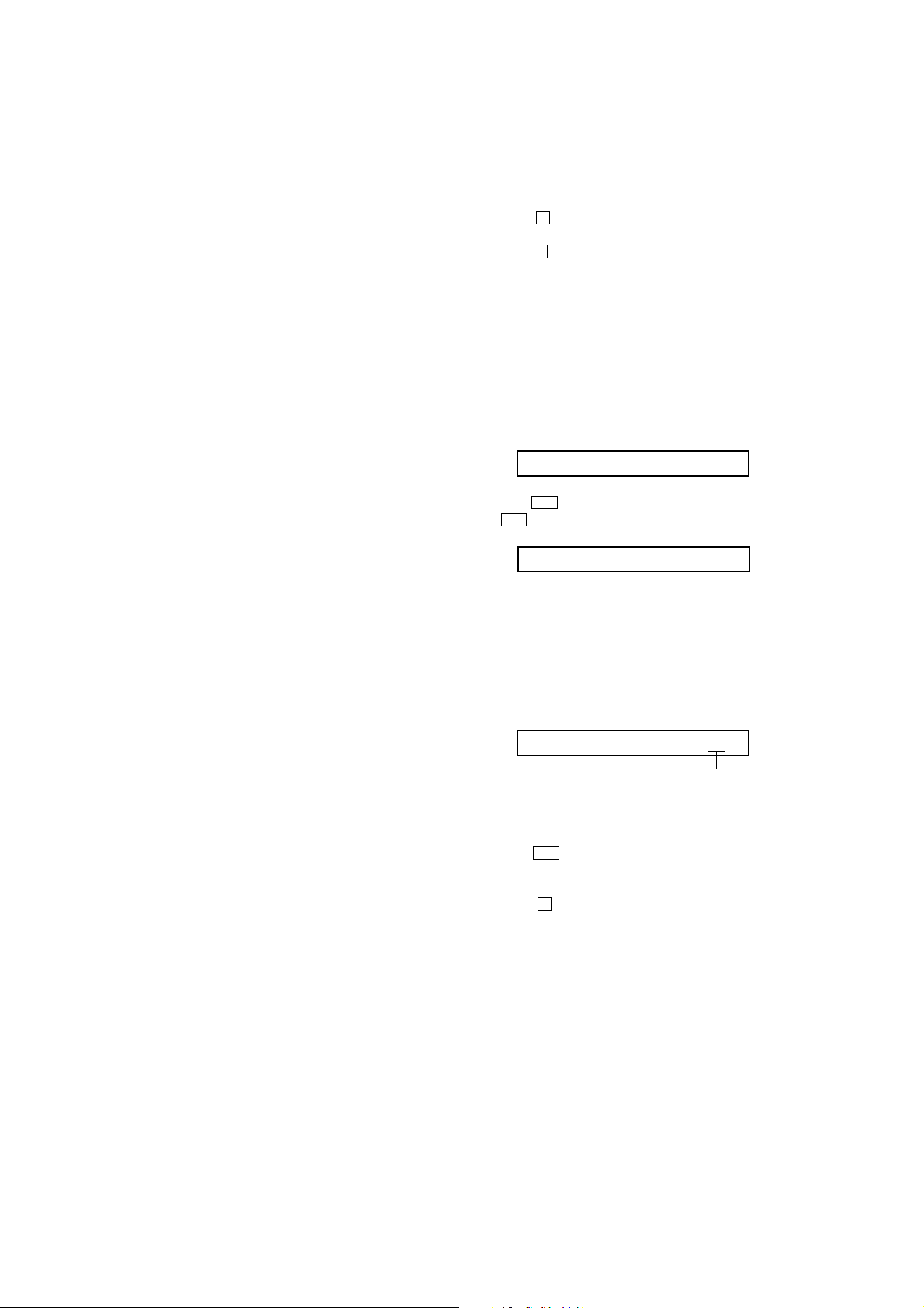
3-6. Servo Overall Adjustment
3-6-1. Operation of the overall adjustment mode
Note1: Be sure to adjustment so that the set is horizontal and the upper
panel is upside. Unless performed in that state, it is not adjusted
correctly.
Note2: If NG is displayed in the middle of this adjustments, perform “3-1.
Initialize The Adjustment Value” and “3-5. Setting The Adjustment
Values” again, then retry this adjustments from step 1.
Procedure:
1. Enter the test mode (Display Check mode).
2. Press the [VOL--] key to enter the Overall Adjustment mode.
3. Insert the CD adjustment disc (TDYS-1).
4. Put the main unit horizontal so that the upper panel becomes
upside, and press the . key.
5. Wait until “CD OK” is displayed on the EL.
6. Insert the MD1/HiMD1 hybrid adjustment disc
(MDW-74/GA2).
7. Put the main unit horizontal so that the upper panel becomes
upside, and press the > key.
8. Wait until “MD1 OK” is displayed on the EL.
9. Insert the Hi-MD3 adjustment disc (HMD1GSDJ).
10. Put the main unit horizontal so that the upper panel becomes
upside, and press the [VOL+] key.
11. Wait until “HMD3OK” is displayed on the EL.
12. Eject the disc and close the upper panel.
13. Put the main unit horizontal so that the upper panel becomes
upside, and press the [VOL--] key.
14. Wait until “OfstOK” is displayed on the EL.
15. Press the x key and back to the Display Check mode.
Flow of overall adjustment mode:
Overall Adjustment Mode
0000 AdjF**
.
key
CD Overall Adjustment Mode
**** CD Run
key
x
3-6-2. Error message in the overall adjustment mode
In the Overall Adjustment mode, if an error occurred, it displa ys as
following table.
Display Description
Close! Dose not close the lid
DfDis! Unsuitableness disc was inserted
NoChg! Does not finish the check of charge function yet
NotCD! Does not complete the CD Overall adjustment before the
MD1 Overall adjustment
NotM1! Does not complete the MD1 Overall adjustment before the
Hi-MD3 Overall adjustment
NotH3! Does not complete the Hi-MD3 Overall adjustment before
the Stray Light Offset Overall adjustment
****NG Error of item number “****”
3-7. Resume Clear
Procedure:
1. Enter the test mode (Display Check mode).
2. Press the [VOL+] key to enter the Manual mode.
3. Press the [VOL+] key once, press the > key once , press the
[VOL--] key once, press the > key once, and press the [VOL+]
key twice, press the > key three times to select the item
number 1933.
4. Press the X key to resume clear.
5. Press the x key four times and back to the Display Check
mode.
3-8. Releasing The Test Mode
Note: When the power supply is switched on in the state where all
electrical adjustments have not finished, it is displayed on EL as
“Error EE’’ and the usual operation can’t be performed. When a
power supply is accidentally turn off in the middle of electrical
adjustments, it is again set as test mode and electrical adjustments
is mode to complete.
>
key
key
x
[VOL +]
key
key
x
[VOL --]
key
key
x
[DISPLAY/MENU]
key
x
[T MARK]
key
key
x
MD1 Overall Adjustment Mode
**** MD1Run
Hi-MD3 Overall Adjustment Mode
**** HM3Run
Stray Light Offset Overall Adjustment Mod
**** OfsRun
Optical Pick-up Operation Check Mode
key
0000 OPChk
Initialize The Adjustment Values
1911 ResOK?
20
 Loading...