

Sony MZR-90 Service manual

MZ-R90/R91
SERVICE MANUAL
Ver 1.4 2001.01
With SUPPLEMENT-1
(9-927-187-83)
Photo: MZ-R91 (Blue type)
US and foreign patents licensed from Dolby
Laboratories Licensing Corporation.
SPECIFICATIONS
System
Audio playing system
MiniDisc digital audio system
Laser diode properties
Material: GaAlAs
Wavelength:λ = 790 nm
Emission duration: continuous
Laser output: lessthan 44.6
(This output is the value measured at a distance
of 200 mm from the lens surface on the optical
pick-upblockwith7mmaperture.)
Recording and playback time
Maximum 80 minutes (MDW-80, stereo
recording)
Maximum 160 minutes (MDW-80,monaural
recording)
Maximum 74 minutes (MDW-74, stereo
recording)
Maximum 148 minutes (MDW-74,monaural
recording)
Revolutions
400 rpm to 1,800 rpm (CLV)
Error correction
Advanced Cross Interleave Reed Solomon
Code (ACIRC)
Sampling frequency
44.1 kHz
Sampling rate converter
Input: 32 kHz/44.1 kHz/48 kHz
Coding
Adaptive TRansform Acoustic Coding
(ATRAC)
Modulation system
EFM (Eight to Fourteen Modulation)
Number of channels
2 stereo channels
1 monaural channel
Frequency response
20 to 20,000 Hz ± 3dB
Wow and Flut ter
Below measurable limit
Inputs
Microphone: stereo mini-jack, 0.35–1.38 mV
Line in: stereo mini-jack,69–194 mV
Optical (Digital) in: optical (digital) mini-jack
Outputs
i/LINE OUT*: stereo mini-jack
Headphones: max
5
mV, load impedance 16 ohm
µW
imum output level 5 mV +
LINE OUT: 194 mV,load impedance 10
kilohm
*Thei/LINE OUT jack connects either
headphones or a line cable.
General
Power requirements
Sony AC Power Adaptor (supplied) connected
at the DC IN 3 V jack:
220–230 V AC, 50/60 Hz (European model)
120 V AC, 50 Hz (Canadian model)
100–240 V AC, 50/60 Hz (Other models)
Nickel metal hydride rechargeable battery NH14WM (supplied)
LR6 (size AA) alkaline battery (not supplied)
Battery operation time
Batter y life
Batteries Recording2)Playback
NH-14WM
nickel metal
hydride
rechargeable
battery
LR6 (SG)
(size AA)
Sony alkaline
dry battery
NH-14WM
nickel metal
hydride
rechargeable
battery
+ One LR6
(SG)
(size
1)
Approx.
6.5 hours
Approx.
4 hours
Approx.
14.5 hours
AA)
US Model
Canadian Model
Australian Model
Chinese Model
MZ-R90
AEP Model
UK Model
E Model
Tourist Model
MZ-R90/R91
Model Name Using Similar Mechanism NEW
Mechanism Type MT-MZR90-165
Optical Pick-up Name LCX-2R
1)
The battery life may be shorter due to
ope
rating conditions and the temperature of
the location.
2)
Approx.
12 hours
Approx.
16.5
hours
Approx.
29 hour
When you record, use
re
chargeable battery.
Dimensions
MZ-R90
Approx. 78.9 × 17.3 × 72.0 mm (w/h/d)
1
(3
/8×11/16× 27/8in.)
MZ-R91
Approx. 78.9 × 18.0 × 72.0 mm (w/h/d)
1
/8×23/32× 27/8in.)
(3
Mass
MZ-R90
Approx. 105 g (3.7 oz) the recorder only
Ap
prox. 148 g (5.2 oz) incl.a recordable MD,
and NH-14WM nickel metal hydride
rechargeable battery
MZ-R91
Approx. 110 g (3.8 oz) the recorder only
Approx. 153
and
NH-14WM nickel metal hydride
rechargeable battery
Supplied accessories
AC power adaptor (1)
Headphones with a remote control (1) (RM-MZ2S)
NH-14WM nickel metal
battery(1)
Dry battery case (1)
Rechargeable battery carrying case (1)
Carrying pouch (1)
A
C plug adaptor (1)
Design and specifications are subject to
change without notice.
a fully charged
g (5.4 oz) incl. a recordable MD,
hydride rechargeable
PORTABLE MINIDISC RECORDER

TABLE OF CONTENTS
1. SERVICING NOTES............................................... 3
2. GENERAL ................................................................... 4
3. DISASSEMBLY ......................................................... 5
4. TEST MODE.............................................................. 11
5. ELECTRICAL ADJUSTMENTS......................... 18
Flexible Circuit Board Repairing
• Keep the temperature of the soldering iron around 270 ˚C during repairing.
• Do not touch the soldering iron on the same conductor of the
circuit board (within 3 times).
• Be careful not to apply force on the conductor when soldering
or unsoldering.
Notes on chip component replacement
• Never reuse a disconnected chip component.
• Notice that the minus side of a tantalum capacitor may be dam-
aged by heat.
6. DIAGRAMS
6-1. Block Diagram –SERVO Section–................................. 23
6-2. Block Diagram –A/D, D/A CONVERTER,
AUDIO Section – ............................................................ 25
6-3. Block Diagram –KEY CONTROL/DISPLAY/
POWER SUPPLY Section – ........................................... 27
6-4. Printed Wiring Board ...................................................... 30
6-5. Schematic Diagram ......................................................... 33
6-6. IC Pin Function Description ........................................... 46
7. EXPLODED VIEWS................................................ 53
8. ELECTRICAL PARTS LIST ............................... 57
CAUTION
Use of controls or adjustments or performance of procedures
other than those specified herein may result in hazardous radiation exposure.
SAFETY-RELATED COMPONENT WARNING!!
COMPONENTS IDENTIFIED BY MARK 0 OR DOTTED
LINE WITH MARK 0 ON THE SCHEMATIC DIAGRAMS
AND IN THE PARTS LIST ARE CRITICAL TO SAFE
OPERATION. REPLACE THESE COMPONENTS WITH
SONY PARTS WHOSE PART NUMBERS APPEAR AS
SHOWN IN THIS MANU AL OR IN SUPPLEMENTS PUBLISHED BY SONY.
ATTENTION AU COMPOSANT AYANT RAPPORT
À LA SÉCURITÉ!
LES COMPOSANTS IDENTIFIÉS P AR UNE MARQUE 0
SUR LES DIAGRAMMES SCHÉMATIQUES ET LA LISTE
DES PIÈCES SONT CRITIQUES POUR LA SÉCURITÉ
DE FONCTIONNEMENT. NE REMPLACER CES COMPOSANTS QUE PAR DES PIÈCES SONY DONT LES
NUMÉROS SONT DONNÉS DANS CE MANUEL OU
DANS LES SUPPLÉMENTS PUBLIÉS PAR SONY.
– 2 –

SECTION 1
SERVICING NOTES
NOTES ON HANDLING THE OPTICAL PICK-UP
BLOCK OR BASE UNIT
The laser diode in the optical pick-up block may suffer electrostatic break-down because of the potential difference generated
by the charged electrostatic load, etc. on clothing and the human
body.
During repair, pay attention to electrostatic break-down and also
use the procedure in the printed matter which is included in the
repair parts.
The flexible board is easily damaged and should be handled with
care.
NOTES ON LASER DIODE EMISSION CHECK
Never look into the laser diode emission from right above when
checking it for adjustment. It is feared that you will lose your sight.
NOTES ON HANDLING THE OPTICAL PICK-UP BLOCK
(LCX-2R)
The laser diode in the optical pick-up block may suffer electrostatic break-down easily. When handling it, perform soldering
bridge to the laser-tap on the flexible board. Also perform measures against electrostatic break-down sufficiently before the operation. The flexible board is easily damaged and should be handled
with care.
• When repairing this device with the power on, if you remove
the MAIN board or open the upper panel assy, this device stops
working.
In this case, you can work without the device stopping by fastening the hook of the open/close detect switch (S801) with tape.
upper panel assy
tape
S801
• This set is designed to perform automatic adjustment for each
adjustment and write its value to EEPROM. Therefore, when
EEPROM (IC802) has been replaced in service, be sure to perform automatic adjustment and write resultant values to the new
EEPROM.
(Refer to Section 5 Electrical Adjustment. (page 18))
MAIN board
laser-tap
OPTICAL PICK-UP FLEXIBLE BOARD
• Replacement of CXD2660GA (IC502) and CXR701080-013GA
(IC801) used in this set requires a special tool. Therefore, they
cannot be replaced.
– 3 –

• LOCATION OF CONTROLS
– The recorder –
1
2
3
4
5
6
7
8
9
– The display window of the recorder –
SECTION 2
GENERAL
0
qa
qs
qd
qf
qg
qh
qj
qk
ql
1 x (stop) /CHARGE button
2 Display window
3 REC indicator
4 DC IN 3V jack
5 Jog lever
6 i/LINE OUT (headphones/line out) jack
7 MIC (PLUG IN POWER) jack
8 LINE IN (OPTICAL) jack
9 HOLD switch
Slide to lock the controls of the recorder.
0 N (play) button
qa X (pause) button
qs T MARK (track mark) button
qd REC (record) switch
qf Battery compartment
qg VOL (volume) +/– buttons
qh OPEN switch
qj END SEARCH button
qk ./> (search/AMS) buttons
ql SYNCHRO REC (synchro-recording)
ON/OFF switch
This section is extracted from
instruction manual.
1
2
3
4
5
6
7
8
9
0
qa
qs
qd
qf
– The headphones with a remote control (RM-MZ2S) –
1
2
3
4
5
6
7
8
9
0
1 Character information display
Displays the disc and track name*,
date, error messages, track numbers,
etc.
* Disc and track names appear only
with MDs that have been
electronically labeled.
2 MONO(monaural) indication
3 Disc name/track name indications
Appears when labeling disc or track
respectively.
4 Play mode indication
Shows the play mode of the MD.
F (all repeat): All tracks play
F 1(single repeat): One track plays
F SHUF(shuffle repeat): Tracks will
5 SYNC (synchro-recording) indication
Lights up while synchro-recording.
6 Disc indication
Shows that the disc is rotating for
recording, playing or editing an MD.
7 REC indication
Lights up while recording. Flashes
when standing by for recording.
1 Headphones
Can be replaced with optional headphones.
2 Stereo mini plug
3 x (stop) button
4 Control
To play, press the control towards
N•> during stop. Press the
control towards N•> during play
to search the beginning of the
succeeding track; hold in this position
to fast-forward. Press towards .
during play to search the beginning of
the preceeding track; hold in this
position to rewind.
5 HOLD switch
Slide to lock the controls of the remote
control.
6 X (pause) button
7 PLAY MODE button
8 DISPLAY button
9 VOL (volume) +/– buttons
When the AVLS is set to on, you
cannot increase the volume to the
maximum. To increase the volume
above the limited level, set the AVLS
to off using the jog lever.
0 Display window
repeatedly.
repeatedly.
be repeated in random
order.
8 Mega bass indication
9 Battery indication
Shows approximate battery condition.
While charging the rechargeable
battery, this indication shows the
charging condition.
0 REMAIN (remaining time/tracks)
indication
Lights up along with the remaining
time of the track, remaining time of the
MD, or remaining number of tracks.
qa REC DATE (recorded/current date)
indication
Lights up along with the date and time
the MD was recorded. When only
“DATE” lights up, the current date
and time are displayed.
qs Time display
Shows the elapsed time of the track
being recorded or played.
qd Level meter
Shows the level of the MD being
played or recorded.
qf AM/PM indication
Lights up along with the time
indication in the 12-hour system.
– 4 –

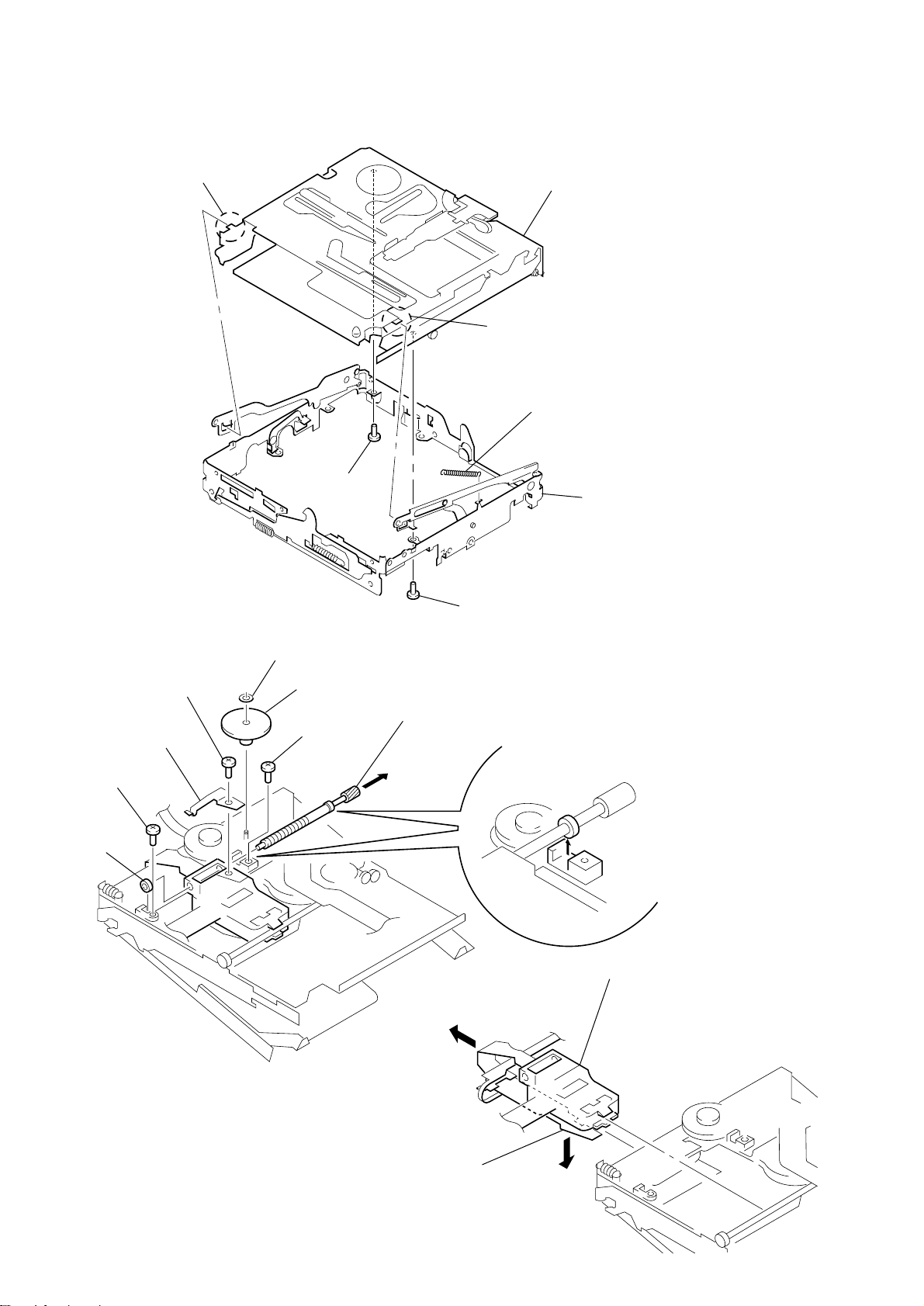
DISASSEMBLY
d
d
• This set can be disassembled in the order shown below.
Main Board, “Case Assy, Battery”
SECTION 3
Set
Note: Follow the disassembly procedure in the numerical order given.
Panel Assy, Bottom
Belt Assy, Ornamental
Service Assy, OP
Motor Flexible Board
Motor, DC (Sled) (M602)
“Motor, DC SSM-01C14A (Spindle) (M601)”, “Motor, DC (Over Write Head Up/Down) (M603)”
Upper Panel Section
Main Board, “Case Assy, Battery”
Holder Assy
PANEL ASSY, BOTTOM
Note: On installation of bottom
panel assy, adjust the position of both two switches
(S804, S807) and two
knobs (hold).
S807
S804
LCD Module, “Button, Control”, “Service Assy, Upper Panel” (R90/R91)
“Chassis Assy, Set”,
MD Mechanism Deck (MT-MZR90-165)
3 battery case li
1 Open the
battery case lid.
4 Close the
battery terminal (plus).
2 two claws
5 two screws
(1.4)
UPPER PANEL SECTION
4 two screws
(1.4)
knob (hold)
5 two screws
(1.4)
6 Remove the bottom panel assy
A
5 screw (1.4)
in the direction of arrow A.
5 upper panel section
4 two screws
(1.4)
1 flexible boar
(CN801)
2 knob (open)
3
– 5 –

e
y
LCD MODULE, “BUTTON, CONTROL”, “SERVICE ASSY, UPPER PANEL”
• MZ-R90
3 control button
4 upper panel service assy
1 five screws
(1.4)
2 LCD modul
• MZ-R91
3 control button
Note: The control buttons are stuck with
strong adhesive sheets.
As the control buttons are very fragile,
do not peel them off forcibly.
1 five tapping screws
(1.7)
2 LCD module
5 upper panel service ass
4 adhesive sheet
(control button)
Note: Also replace the adhesive sheets (control button),
when replacing the control buttons and upper panel
service assy.
– 6 –

MAIN BOARD, “CASE ASSY, BATTER Y”
2 flexible board (over write head)
(CN601)
2 flexible board (LCD module)
(CN801)
3 four toothed lock screws
(M1.4)
6 main board
1 Remove the solder of
battery terminal (plus).
5 flexible board
(optical pick-up)
(CN501)
Note: Before removing the flexible board
from CN501, be sure to solder the
flexible board.
(Refer to servicing notes (NOTES ON
HANDLING THE OPTICAL PICK-UP
BLOCK (LCX-2R)) page 3.)
4
1 Remove the solder of joint.
1 Remove the solder of
battery terminal (minus).
8 batter case assy
2 motor flexible board
(CN602)
7 four bosses
BELT ASSY, ORNAMENTAL
Note: As the ornamental belt assy
is very fragile, do not give an
excessive force to the entire
assy when removing it.
6 Remove the ornamental belt assy
in the direction of arrow C.
3 three bosses
)
C
B
boss
@
A
)
2 Open toward the direction B
to disengage two bosses
and convex portions pointed
*
.
with
4 knob (open)
^
B
)
boss
1 Pull toward the direction A
to disengage two bosses .
A
)
2 Open toward the direction B
to disengage two bosses
and convex portions pointed
*
.
with
boss
5 two bosses
@
boss
– 7 –
y
e
“CHASSIS ASSY, SET”, MD MECHANISM DECK (MT-MZR90-165)
2 boss
3 MD mechanism deck
(MT-MZR90-165)
2 boss
4 tension spring (arm)
1 screw (1.4)
5 set chassis ass
1 screw (1.4)
SERVICE ASSY, OP
3 precision pan screw
(M1.4)
4 rack spring
5 screw
8 bearing
1 washer (0.8 - 2.5)
2 gear (SA)
5 screw
7 Pull off the lead screw.
B
6
9 Opening the over write head
toward the direction A, remove th
OP Service assy toward
the direction B.
Note: Do not open the entire assy
forcibly, when opening
the over write head.
over write head section
– 8 –
A

HOLDER ASSY
1 Open the holder assy.
5 Remove the holder assy in the
direction of arrow C.
A
B
2 Push the convex portion
toward the direction B and
open the holder assy toward
the direction A to erect uprightly.
3
C
MOTOR FLEXIBLE BOARD
1 Remove four solders of
DC motor (sled) (M602).
2 adhesive sheet
Note: Align a circular hole in the stripping paper
with a circular hole in the DC motor (sled),
when mounting the motor
flexible board.
4 boss
1 Remove two solders of
DC motor (over write head up/down) (M603).
1 Remove four solders of
DC motor (spindle) (M601).
3 motor flexible board
DC motor (sled)
circular hole
– 9 –

MOTOR, DC (SLED) (M602)
1 Remove four solders of
motor flexible board.
4 two precision pan screws
(M1.4)
5 DC motor (sled) (M602)
2 washer (0.8 - 2.5)
3 gear (SA)
“MOTOR, DC SSM-01C14A (SPINDLE) (M601)”,
“MOTOR, DC (OVER WRITE HEAD UP/DOWN) (M603)”
1 Remove six solders of
motor flexible board.
4 three precision pan screws
(M1.4)
qa DC motor (over write head up/down)
(M603)
6 two precision pan screws
(M1.4)
qs gear chassis assy
9 screw
(M1.2 × 1.5)
Note: Press-fit the gear (HA) up to the
position of the DC motor (over write
head up/down) (M603) as shown
below.
gear (HA)
2.65 mm
gear chassis assy
DC motor
(over write head up/down)
(M603)
0 gear (HA)
8 gear (HB)
7 washer (0.8 - 2.5)
2 washer (0.8 - 2.5)
3 gear (HC)
5 DC motor
(spindle)
(M601)
– 10 –
SECTION 4
TEST MODE
[Outline]
• This set provides the Overall adjustment mode (Assy mode) that
allows CD and MO disc to be automatically adjusted when in
the test mode. In this overall adjustment mode, the protect switch
is detected to judge the disc, CD or MO, and each adjustment is
automatically executed in order. If a fault is found, the system
displays its location. Also, the manual mode allows each individual adjustment to be automatically adjusted.
• The keys in the description refer to the keys on both set and
remote commander unless otherwise specified. Though LCD
display shows the LCD of the remote commander, same contents are also displayed on the LCD of the set.
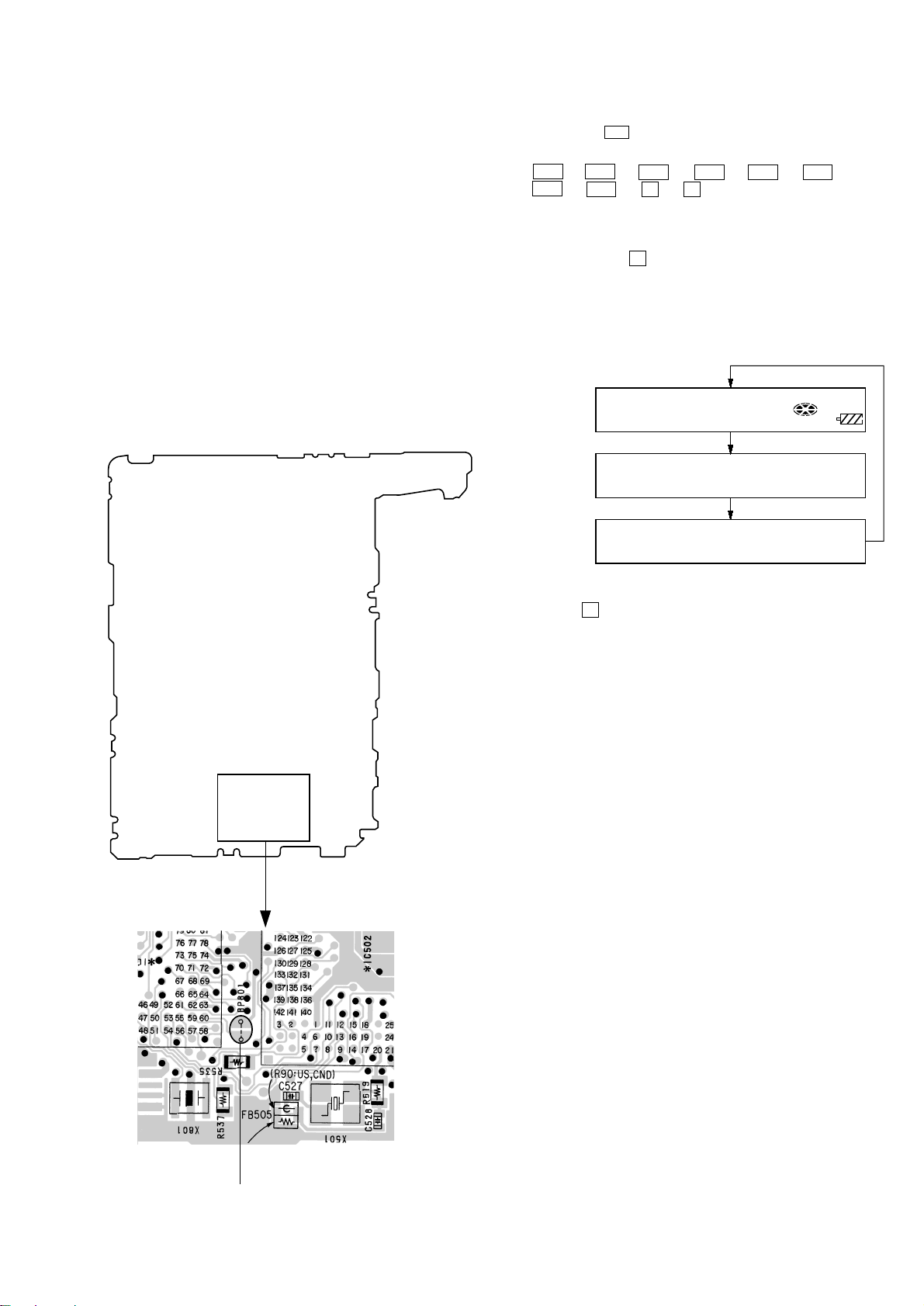
[Setting Method of Test Mode]
There are two different methods to set the test mode:
1 Short BP801 (TEST) on the MAIN board with a solder bridge
(connect pin y; of IC801 to the ground). Then, turn on the
power.
– MAIN BOARD (Conductor Side) –
2 In the normal mode, turn on the HOLD switch on the set. While
pressing the N key on the set, press the following set keys
in the following order:
> t > t . t . t > t . t
> t . t X t X
[Operation in Setting the Test Mode]
• When the test mode becomes active, first the display check mode
is selected. (Press x key once, when the display check mode
is not active.)
• Other mode can be selected from the display check mode.
• When the test mode is set, the LCD repeats the following display.
LCD display
All lit
All off
Microprocessor
version
display
888
xxxxxxxxx
001
V0.000
F1SHUF
REC
• When the X key is pressed and hold down, the display at that
time is held so that display can be checked.
[Releasing the Test Mode]
For test mode set with the method 1:
Turn off the power and open the solder bridge on BP801 (TEST)
on the MAIN board.
Note: Remove the solders completely. Remaining could be shorted with
the chassis, etc.
For test mode set with the method 2:
Turn off the power.
Note: If electrical adjustment (see page 18) has not been finished com-
pletely, always start in the test mode. (The set cannot start in normal mode.)
BP801
Short: Test Mode
Open: Normal Mode
)(
– 11 –

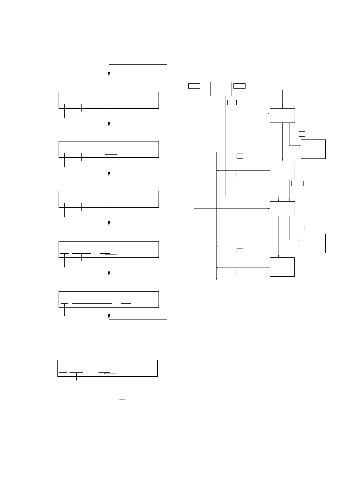
[Configuration of Test Mode]
[Test Mode $Display Check Mode%]
Press the
>
or
[VOL +]
key
[Manual Mode]
Press the
Press the
x
key
.
or
[VOL --]
key
[Overall Adjustment Mode]
Press the
x
key
[Servo Mode]
[Audio Mode]
[Power Mode]
[OP Alignment Mode]
[Major item switching]
N
key x key
[Medium item switching]
N
key
x
key
[Minor item switching]
[VOL +]
[VOL --]
key:100th place of mode number
increase.
key:100th place of mode number
decrease.
[VOL +]
[VOL --]
key:10th place of mode number
increase.
key:10th place of mode number
decrease.
N
key: Unit place of mode number
increase.
Press the
Press the
N
x
or
key
[REC]
key on the set
[Sound Skip Check Result Display Mode]
Move up the jog key on the set or
press the
on the remote commander
[DISPLAY]
key
[Self-Diagnosis Display Mode]
Press the
Press the
on the remote commander for several seconds.
x
key
[T MARK]
or
[DISPLAY]
key
[Key Check Mode]
Quit the key check or open the upper panel
[Manual Mode]
Mode to adjust or check the operation of the set by function.
Normally, the adjustment in this mode is not executed.
• Transition method in Manual Mode
1. Setting the test mode. (See page 11)
2. Press the
where the LCD display as shown below.
> or [VOL +] key activates the manual mode
LCD display
000
Manual
[Adjusted value variation]
[VOL +]
[VOL --]
key:Increases the
adjusted value
key:Decreases the
adjusted value
[Adjusted value write]
X
key: When adjusted value is
changed:
Adjusted value is written.
When adjusted value is
not changed:
That item is adjusted
automatically.
3. The optical pick-up moves outward or inward while
the > or . key is pressed for several seconds respectively.
4. Each test item is assigned with a 3-digit mode number;
100th place is a major item, 10th place is a medium item, and
unit place is a minor item.
– 12 –
5. The display changes a shown below each time the jog key on
the set is turned up or [DISPLAY] key on the remote commander is pressed.
• Address & Adjusted Value Display
LCD display
011
C68S01
address
mode number
• Jitter Value & Adjusted Value Display
LCD display
011
0FFJ01
jitter value
mode number
• Block Error Value & Adjusted Value Display
LCD display
011
063B01
block error value
mode number
• ADIP Error Value & Adjusted Value Display
LCD display
011
059A01
ADIP error value
mode number
• Item Title Display
LCD display
011
LrefPw 01
adjusted value
adjusted value
adjusted value
adjusted value
[Overall Adjustment Mode]
Mode to adjust the servo automatically in all items.
Normally, automatic adjustment is executed in this mode at the
repair.
Adjust the CD first, when performing adjustment.
• Configuration of overall adjustment
> key . key
Title
display
N key
protect switch ON
protect switch OFF
x key
x key
x key
x key
CD overall
adjusting
All item
OK
CD overall
adjustment
MO overall
adjusting
MO overall
adjustment
OK
> key
OK
NG item exists
x key
or
CD overall
adjustment
NG
NG item exists
or
x key
MO overall
adjustment
NG
[Test mode $display check mode%]
For further information, refer to the Section 5 Electrical Adjustment. (See page 18)
item title
mode number
However in the power mode (mode number 700’s), only the
power adjustment value is displayed.
• Power Supply Adjusted Value
LCD display
731
AD 85
fixed display
mode number
6. Quit the manual mode, and press
mode (display check mode).
adjusted value
adjusted value
x key to return to the test
– 13 –

[Sound Skip Check Result Display Mode]
This set can display and check the error count occurring during
record and play.
• Setting method of Sound Skip Check Result Display
Mode
1. Setting the test mode. (See page 11)
2. Press the N or [REC] key on the set activates the sound skip
check result display mode where the LCD displays as shown
below.
If microprocessor version is 1.20
When N key is pressed:
LCD display
000
Stat**
Total of play system error count
When [REC] key on the set is pressed:
LCD display
000
Rtry**
Total of record system error count
If microprocessor version is 1.30 or later
When N or [REC] key on the set is pressed:
LCD display
000
P**R**
Total of record system
error count
Total of play system error count
3. When
N key is pressed, the total of error count is displayed
on the LCD, and each time the > key is pressed, the error
count descents one by one as shown below. Also,
when . key is pressed, the error count ascends by one. If
[REC] key on the set is pressed, the error count during record
is displayed.
4. When [REC] key on the set is pressed, the total of error count
is displayed on the LCD, and each time the > key is
pressed, the error count descents one by one as shown below.
Also, when . key is pressed, the error count ascends by
one. If N key is pressed, the error count during play is displayed.
If microprocessor version is
1.20.
000
Rtry**
000
######
000
BOvr**
000
Bful**
**
: Sound skip check items counter (hexadecimal)
######
: 6-digit address (hexadecimal) where a sound skipped
last
If microprocessor version is
1.30 or later.
000
P**R**
000
BOvr**
000
Bful**
000
Rtry**
000
######
Error code
Cause of error Description of error
EIB Sound error correction error
Playback
Recording BFul Buffer capacity lowers and data are
Stat Decorder status error
Adrs Cannot access the address
BEmp Buffer becomes empty
BOvr Buffer becomes full and sounds are
dumped
forcibly written
Rtry Retry count over
5. Quit the sound skip check result display mode, and press
the x key to return to the test mode (display check mode).
If microprocessor version is
1.20.
000
Stat**
000
BEmp**
000
######
000
EIB **
**
: Sound skip check items counter (hexadecimal)
######
: 6-digit address (hexadecimal) where a sound skipped
last
If microprocessor version is
1.30 or later.
000
P**R**
000
EIB **
000
Stat**
000
Adrs**
000
BEmp**
000
######
– 14 –

[Self-Diagnosis Display Mode]
• This set uses the self-diagnosis system in which if an error oc-
curs in recording/playback mode, the error is detected by the
model control and power control blocks of the microprocessor
and information on the cause is stored as history in EEPROM.
By viewing this history in test mode, it helps you to analyze a
fault and determine its location.
Total recording time has been recorded as optical pick-up using
time, and it is compared with the total recording time in the
self-diagnosis display mode to find when an error occurred.
Clear both total recording time and the time in self-diagnosis
display mode, when the optical pick-up was replaced.
1. Setting the test mode. (See page 11)
2. Move up the jog key on the set or press the [DISPLAY] key on
the remote commander activates the self-diagnosis display mode
where the LCD display as shown below.
LCD display
000
1st0**
history code
** : Self-Diagnosis Data
3. Then, each time > key is pressed, LCD display descends
by one as shown below. Also, the LCD display ascends by one
when . key is pressed.
000
1st0**
000
1st1**
000
1st2**
000
N 0**
000
N 1**
000
N 2**
000
N-10**
1
1
000
N-11**
000
N-12**
000
N-20**
000
N-21**
000
N-22**
000
R ####
4. Quit the self-diagnosis display mode, and press the
return to the test mode (display check mode).
x key to
– 15 –
 Loading...