

Sony MEXR-1 Service manual
MEX-R1
SERVICE MANUAL
Ver. 1.0 2005.03
US and foreign patents licensed from Dolby
Laboratories.
Copyrights
This product incorporates copyright pro te ct ion
technology t hat is protected by method claims of
certain U.S. pa tents, other intellectual property
rights owned by Macrovision Corporat i on, and
other rights owners. Use of this copyright
protectio n technology must be authorized by
Macrovision Corporation, and is intended for
home and other limited viewing uses only unless
otherwise authorized by Macrovision
Corporation. Reverse engineering or disassembly
is prohibited.
Manufactured under license from Dolby
Laboratories.
“Dolby” and the double-D symbol are
trademarks of Dolby Laboratories.
Confidential unpublished works. Copyri ght
1992−1997 Dolby Laboratories. All rights
reserved.
“DTS” and “DTS 2.0 + Digital Out” are
trademarks of Digital Theater System s, Inc.
System
Laser Semiconductor laser
Signal format system AEP, UK models: PAL
DVD/CD Player section*
Signal-to-noise ratio 120 dB
Frequency response 10 − 20,000 Hz
Wow and flutter Below measurable limit
Harmonic distortion (DVD)
Wow and flutter Less than detected value
*
Measured from the AUDIO OUT jacks.
When you play PCM sound tracks with a 96 kHz
sampling frequency, the output signals from the
DIGITAL OUT jack are converted to 96 kHz
sampling frequency.
Tuner section
FM
Tuning range AEP, UK, Asian models:
Aerial terminal External aerial connector
Intermedia te freq u ency 10.7 MHz/450 kHz
Usable sensitivity 9 dBf
Selectivity 75 dB at 400 kHz
Signal-to-noise ratio 67 dB (stereo), 69 dB
Harmonic distortion at 1 kHz
Separation 35 dB at 1 kHz
Frequency response 30 − 15,000 Hz
MW/LW
Tuning range AEP, UK, models:
Aerial terminal External aerial connector
Intermedia te freq u ency 10.7 MHz/450 kHz
Sensitivity MW: 30 µV, LW: 40 µV
Except AEP, UK model:
PAL/NTSC switchable
0.01%
(±0.001 % W PEAK)
87.50 − 108.00 MHz
Latin American model:
87.50 − 107.90 MHz
(mono)
0.5 % (stereo),
0.3 % (mono)
MW: 531 − 1,602 kHz
LW: 153 − 279 kHz
Asian model:
531 − 1,602 kHz (at 9 kHz step)
Latin American model:
530 − 1,710 kHz (at 10 kHz step)
AEP Model
UK Model
E Model
Model Name Using Similar Mechanism NEW
DVD Mechanism Type MG-612-187
Optical Pick-up Block Name KHS-340B
SPECIFICATIONS
Power amplifier section
Outputs Speaker outputs (sure seal
Speaker impedance 4 − 8 ohms
Maximum power output 52 W × 4 (at 4 ohms)
General
Outputs Front audio/video output terminals
Inputs Telephone ATT control terminal
Tone controls Bass: ±8 dB at 100 Hz
Loudness +8 dB at 100 Hz
Power requirements 12 V DC car battery
Dimensions Approx. 178 × 50 × 182 mm (w/h/d)
Mounting dimensions Approx. 182 × 53 × 161 mm (w/h/d)
Mass Approx. 1.3 kg
Supplied accessories Card remote commander
Note
This unit cannot be connected to a digital preamplifier or an
equalizer which is Sony BUS system compatible.
Design and specifications are subject to change without
notice.
connectors)
Rear audio (Z×Z)/video output
terminals
Rear audio output terminal
Subwoofer output terminal
(mono)
Optical digital output terminal
Power aerial relay control terminal
Power amplifier control terminal
Illumination control terminal
BUS control input terminal
BUS audio input/AUX IN terminal
Parking break control terminal
Remote controller input terminal
Aerial input terminal
Treble: ±8 dB at 10 kHz
+2 dB at 10 kHz
(negative earth)
RM-X702
(Except AEP, UK model)
RM-X703 (AEP, UK models)
Parts for installation and
connections (1 set)
Front panel case (1)
9-879-420-01
2005C05-1
© 2005.03
MULTI DISC PLAYER
Sony Corporation
e Vehicle Group
Published by Sony Engineering Corporation
MEX-R1
CAUTION
The use of optical instruments with this
product will increase eye hazard.
CAUTION
Use of controls or adjustments or performance of procedures
other than those specified herein may result in hazardous radiation
exposure.
Notes on chip component replacement
• Never reuse a disconnected chip component.
• Notice that the minus side of a tantalum capacitor may be
damaged by heat.
Flexible Circuit Board Repairing
• Keep the temperature of the soldering iron around 270 ˚C
during repairing.
• Do not touch the soldering iron on the same conductor of the
circuit board (within 3 times).
• Be careful not to apply force on the conductor when soldering
or unsoldering.
This label is located on the bottom of the
chassis.
CAUTION
RADIATION WHEN OPEN AND INTERLOCKS DEFEATED.
DO NOT VIEW DIRECTLY WITH OPTICAL INSTRUMENTS.
This label is located on the drive unit's internal
chassis
:CLASS 1M VISIBLE/INVISIBLE LASER
TABLE OF CONTENTS
1. SERVICING NOTES ............................................... 3
2. GENERAL ................................................................... 6
3. DISASSEMBLY
3-1. Disassembly Flow ........................................................... 10
3-2. SUB Panel Complete Assy .............................................. 10
3-3. DVD Mechanism Deck (MG-612-187)........................... 10
3-4. MAIN Board, DC Fan (25X25) (M901) ......................... 11
3-5. Chassis (T) SUB Assy ..................................................... 11
3-6. Roller ARM Assy ............................................................ 12
3-7. Shassis (OP-DVD) Complete Assy ................................. 12
3-8. Shassis (OP-DVD) SUB Assy ......................................... 13
3-9. LE Motor Assy (Loading) (M3) ...................................... 13
3-10. SERVO Board.................................................................. 14
3-11. Front Back Panel (LCD).................................................. 14
3-12. BASE Board .................................................................... 15
3-13. Display Section................................................................ 15
3-14. Bracket (Display) ............................................................ 16
3-15. Spring (S) ........................................................................ 16
4. ELECTRICAL ADJUSTMENTS
SERVO Section ............................................................... 17
5. DIAGRAMS
5-1. Block Diagram – SERVO Section –................................ 18
5-2. Block Diagram – AUDIO Section – ................................ 19
5-3. Block Diagram – MAIN Section –.................................. 20
5-4. Printed Wiring Board − SERVO Section (1/2) − ............. 22
5-5. Printed Wiring Boards − SERVO Section (2/2) − ........... 23
5-6. Schematic Diagram − SERVO Section (1/3) −................ 24
6-7. Schematic Diagram − SERVO Section (2/3) −................ 25
6-8. Schematic Diagram − SERVO Section (3/3) −................ 26
6-9. Schematic Diagram – MAIN Section (1/3) – .................. 27
5-10. Schematic Diagram – MAIN Section (2/3) – .................. 28
5-11. Schematic Diagram – MAIN Section (3/3) – .................. 29
5-12. Printed Wiring Board − MAIN Section (1/2) − ............... 30
5-13. Printed Wiring Boards − MAIN Section (2/2) − ............. 31
5-14. Printed Wiring Board − BASE Board − .......................... 32
5-15. Schematic Diagram – BASE Board – ............................. 33
5-16. Printed Wiring Board − DISPLAY Board − .................... 34
5-17. Schematic Diagram – DISPLAY Board – ....................... 35
5-18. Printed Wiring Board − PRESET Board − ...................... 36
5-19. Schematic Diagram – PRESET Board – ......................... 36
6. EXPLODED VIEWS
6-1. General Section ............................................................... 55
6-2. Front Panel Section ......................................................... 56
6-3. DVD Mechanism Deck Section-1 (MG-612-187) .......... 57
6-4. DVD Mechanism Deck Section-2 (MG-612-187) .......... 58
6-3. DVD Mechanism Deck Section-3 (MG-612-187) .......... 59
7. ELECTRICAL PARTS LIST................................ 60
2
SECTION 1
2
SERVICING NOTES
MEX-R1
NOTES ON HANDLING THE OPTICAL PICK-UP
BLOCK OR BASE UNIT
The laser diode in the optical pick-up block may suffer electrostatic
break-down because of the potential difference generated by the
charged electrostatic load, etc. on clothing and the human body.
During repair, pay attention to electrostatic break-down and also
use the procedure in the printed matter which is included in the
repair parts.
The flexible board is easily damaged and should be handled with
care.
NOTES ON LASER DIODE EMISSION CHECK
Never look into the laser diode emission from right above when
checking it for adjustment. It is feared that you will lose your sight.
UNLEADED SOLDER
Boards requiring use of unleaded solder are printed with the leadfree mark (LF) indicating the solder contains no lead.
(Caution: Some printed circuit boards may not come printed with
the lead free mark due to their particular size)
: LEAD FREE MARK
Unleaded solder has the following characteristics.
• Unleaded solder melts at a temperature about 40 ˚C higher
than ordinary solder.
Ordinary soldering irons can be used but the iron tip has to be
applied to the solder joint for a slightly longer time.
Soldering irons using a temperature regulator should be set to
about 350 ˚C.
Caution: The printed pattern (copper foil) may peel away if
the heated tip is applied for too long, so be careful!
• Strong viscosity
Unleaded solder is more viscou-s (sticky, less prone to flow)
than ordinary solder so use caution not to let solder bridges
occur such as on IC pins, etc.
• Usable with ordinary solder
It is best to use only unleaded solder but unleaded solder may
also be added to ordinary solder.
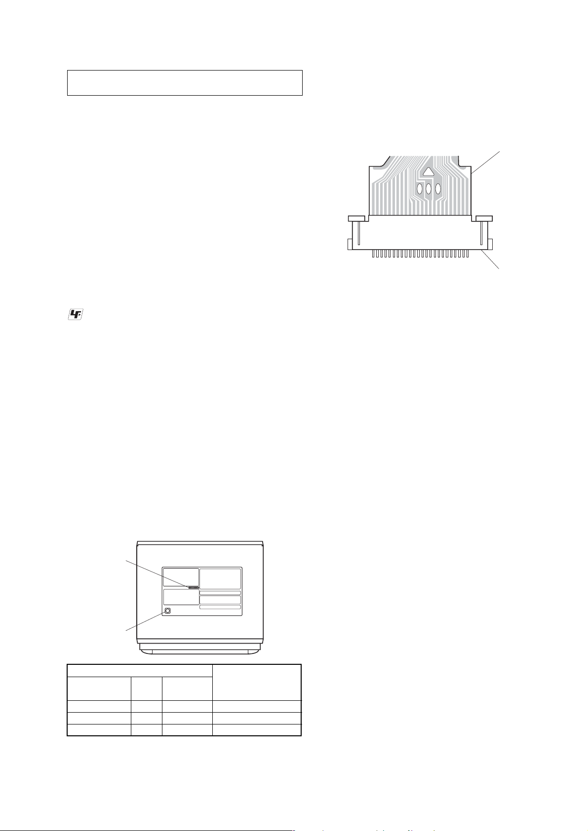
MODEL IDENTIFICATION
– Bottom View –
Part Number
NOTE FOR FLEXIBLE BOARD OF THE OPTICAL
PICK-UP
When connecting or disconnecting the flexible board of the optical
pick-up to or from the CN2 of the SERVO board, follow the
procedure given below.
Flexible board of
the optical pick-up
4
21
3
SERVO board CN
Figure 1
Note: When soldering the short lands, solder within 5 seconds at the
temperature of soldering iron below 300°C.
Disconnection:
1. Solder the lands 3 and 2 to short.
2. Solder the lands 1 and 2 to short.
3. Disconnect the flexible board. (Unsolder the shorted lands)
Connection:
1. Make sure that the lands 1, 2, and 3 of the flexible board to be
connected are soldered to short.
2. Connect the flexible board to the CN2 of the SERVO board.
3. Unsolder the lands 1 and 2.
4. Unsolder the lands 3 and 2.
(*1)
(*2)
(*2)
5. Make sure that the respective lands are open surely.
*1) If the lands concerned are not soldered to short, first solder the lands
3 and 2, and then lands 1 and 2 to short in this order.
*2) When unsoldering the lands, move the soldering iron in bottom to
top direction in Figure 1 so that the solder runs away into the land 4
(solder reservoir) for easy unsoldering.
NOTE FOR OPERATION CHECK WITH THE BASE
BOARD DISCONNECTED
This set detects whether the front panel is opened or closed by using
the S961 of the BASE board. If the BASE board is disconnected,
the S961 is turned off (panel closed status) and the disc is not ejected.
To perform the disc ejecting operation with the BASE board
disconnected, turn on the S961.
Region Code
Label indication
Signal format Region
system code
PAL22-581-683-01 AEP, UK models
PAL42-586-472-01 E: PAL, Korean models
NTSC 3 2-586-473-01 E: NTSC model
Part No.
Destination
NOTE FOR REPLACING THE MOUNTED MAIN
BOARD
If the mounted MAIN board was replaced, be sure refer to T echnical
News published separately.
3

MEX-R1
d
EXTENSION CABLE AND SERVICE POSITION
When repairing or servicing this set, connect the jig (extension cable)
as shown below.
• Connect the MAIN boar d (CN101) and the SERVO board
(CN3) with the extension cable (Part No. J-2502-094-1).
MAIN board
(CN101)
extension cable
(Part No. J-2502-094-1)
SERVO boar
(CN3)
4
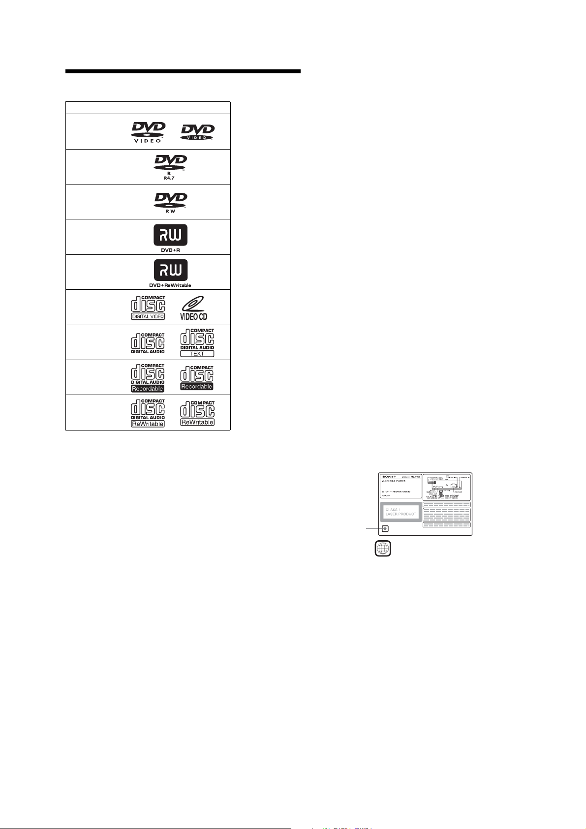
Playable discs
*
Discs that are not finalized cannot be played.
“DVD VIDEO,” “DVD-R,” “DVD-RW,” “DVD+R,” and
“DVD+RW” are trademarks.
DVD
A DVD contains both audio and visual data. A 12 cm disc can hold
7 times the amount of datacontained in a CD-ROM, which equals to 4
consecutive hours of playing time (8 hours for double-sided discs).
DVDs are divided into 4 types: single sided single layer, single sided
double layer, double sided single layer, and double sided double layer.
Format of discs
DVD VIDEO
DVD-R*
(MP3/JPEG)
DVD-RW*
Video mode/VR mode
(MP3/JPEG)
DVD+R*
(MP3/JPEG)
DVD+RW*
(MP3/JPEG)
Video CD
Audio CD
CD-R*
(MP3/JPEG)
CD-RW*
(MP3/JPEG)
Video CD (VCD)
A Video CD can contain both audio and visual data on a disc the same
size as a regular Audio CD. The playing time is 74 minutes for a
standard 12 cm CD .
Audio CD
An Audio CD containing audio data. The playing time is 74 minutes
for a standard 12 cm CD.
CD-Recordable (CD-R)
With a CD-R, you can edit audio data. You can write information on a
CD-R only once.
CD-Rewritable (CD-RW)
With a CD-RW, you can edit audio data. You can write information
on a CD-RW again and again.
CD-Extra
A CD-Extra has two sections (sessions) for audio nd data respectively.
You can only play the section of audio on this unit.
Notes
•
This unit conforms to the PAL colour system. A disc recorded in a colour
system other than PAL, such as NTSC or SECAM, cannot be played.
•
You can play DVD-Rs/DVD-RWs, DVD+Rs/DVD+RWs and CD-Rs/CD-RWs
designed for audio with this unit. However, depending on the recorded
conditions, you cannot play some discs.
•
You cannot play CD-Rs/CD-RWs, DVD-Rs/DVD-RWs or DVD+Rs/
DVD+RWs that are not finalized.
•
Discs created in Packet Write format cannot be played.
•
Recordable discs may not play back correctly if the ambient temperature is
high.
•
The discs listed below cannot be played on this unit:
−
8 cm discs
−
CD-ROM (the data other than the MP3 or JPEG files)
−
−
CD-G
Photo-CD
−
VSD (Video single disc)
−
DVD-ROM (the data other than the MP3 or JPEG files)
−
−
DVD-RAM
DVD-Audio
−
DVD+R DL (Dual Layer)
−
Active-Audio (Data)
−
CD-Extra (Data)
−
Mixed CD
−
−
SVCD (Super Video CD)
CDV
−
SACD (Super Audio CD)
Note on transparent discs
12 cm discs containing of only an inner 8 cm data portion
(the rest is transparent) cannot be played on this unit.
Region code
This system is used to protect software copyrights.
The region code is located on the bottom of the unit, and only DVDs
labelled with an identical region code can be played on this unit.
DVD s labelled can be also pl ayed on this unit.
If you try to play any other DVD, the message “Cannot play this disc.”
will appear on the monitor screen. Depending on the DVD, no
region code may be labelled even though playing the DVD is
prohibited by area restrictions.
Region code
ALL
MEX-R1
5
MEX-R1
SECTION 2
GENERAL
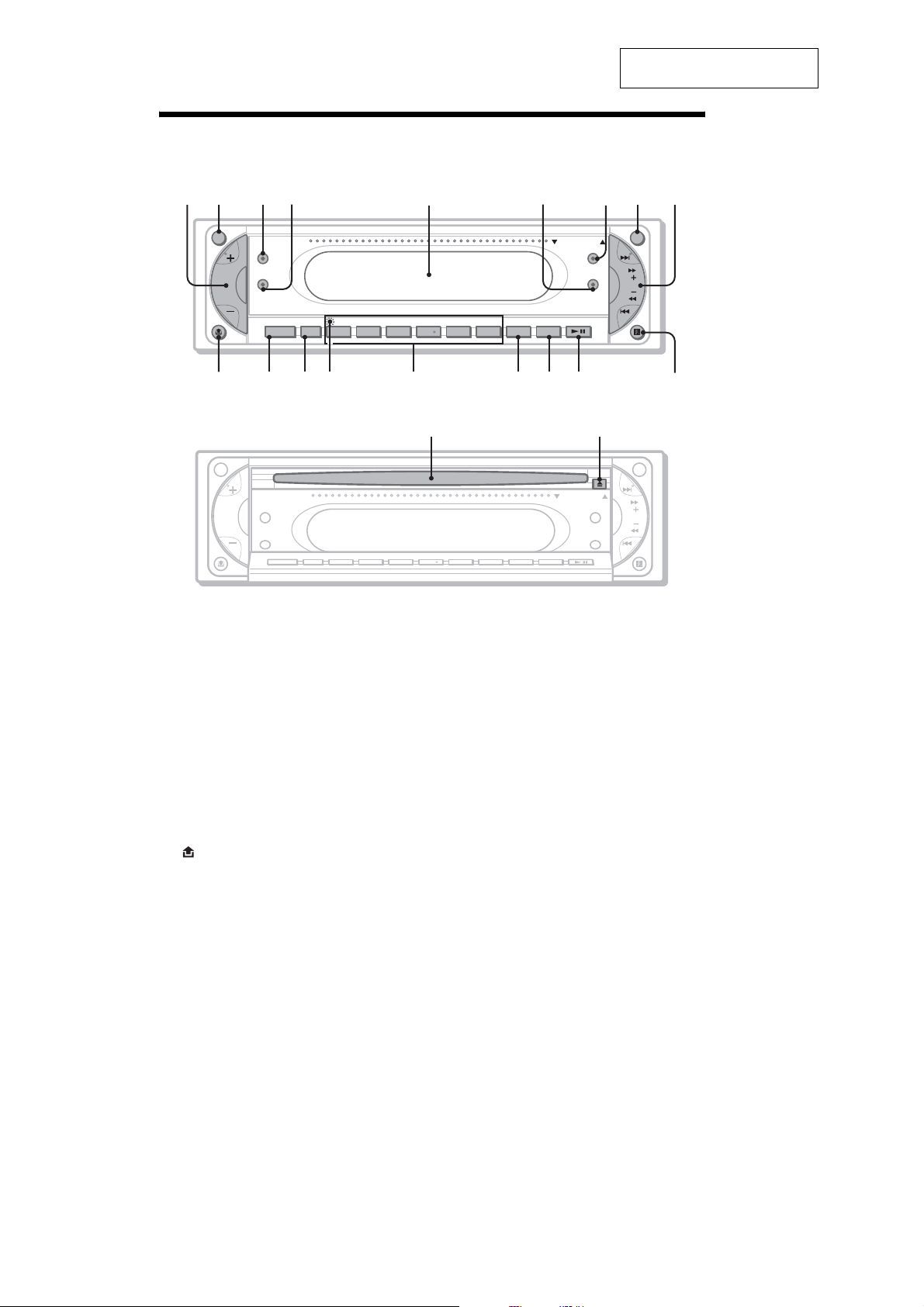
Location of controls and basic operations
Main unit
This section is extracted from
instruction manual.
12 34 6 78 9
ATT OFF
Z
×
Z
SOUND
SOURCE MODE
SHUFREP ALBM +
5
OPEN/CLOSE
DSO
EQ7
-
654321
AF/TA
PICTURE DVD
EQ
SEEK
MEX-R1
(AEP, UK models)
qjqhqgqfqdqsqa0
OPEN/CLOSE shutter opened
ql w;
ATT OFF
OPEN/CLOSE
Z
×
Z
SOUND
SOURCE MODE
Refer to the pages listed for details.
a Volume +/– button
b ATT (attenuate) button
c Z×Z (Zone × Zone) button
d SOUND button
e Di spl ay window
f EQ 7 ( equalizer) button
g DSO button
h OFF button
i SEEK +/– button
Radio:
To tune in stations automatically (press); f ind
a station manual l y (p ress and hold).
DVD/CD:
To skip chapters/tracks (press); fast-forwa rd/
reverse a chapter/t rack (press and h old).
j (front panel release) button
k SOURCE button
l MODE button
m RESET button (located behind the front
panel)
DSO
AF/TA
654321
EQ7
DVDPICTURESHUFREP ALBM +
EQ
n Number buttons
Radio:
To receive stored stations (press); store
stations (press an d hold).
CD/MD*
1
:
(1): REP
(2): SHUF
(3)/(4): ALBM –/+*
To skip albums (press ); skip albums
continuously (press and hold).
o AF (Alternative Frequencies)/TA
(T
raffic Announcement) button
(AEP, UK models)
DSPL button (Except AEP, UK model)
p PICTURE EQ button (AEP, UK models)
SCRL button (Except AEP, UK model)
To scroll the display items.
q DVD u (play/pause) button
r Receptor for the card remote
commander
s Disc slot
t Z (eject) button
SEEK
2
qk
*1
When an MD changer is connected.
*2
When an MP3/JPEG is played and a changer is not
connected.
6
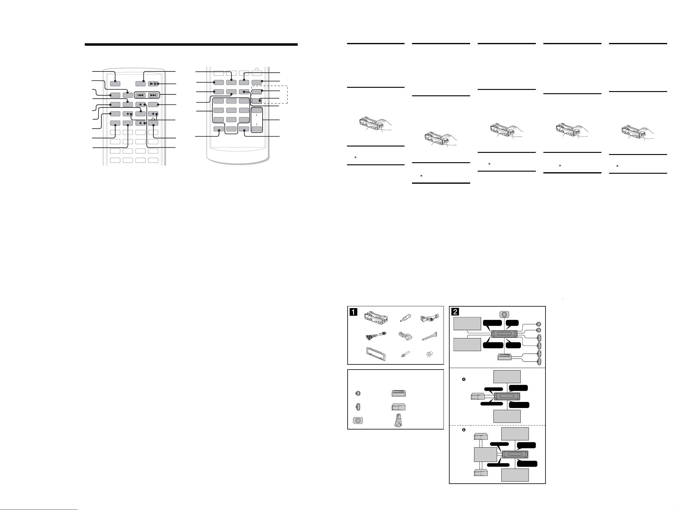
Card remote commander RM-X702 (Except AEP, UK model),
Let op
• Dit apparaat is ontworpen voor gebruik op een auto-accu van 12 V
gelijkstroom, negatief geaard.
• Zorg ervoor dat de draden niet onder een schroef of tussen bewegende
onderdelen (b.v. zetelrail) terechtkomen.
• Voordat u de aansluitingen maakt, moet u het contact uitzetten om
kortsluiting te vermijden.
• Sluit het netsnoer ʎ aan op het apparaat en de luidsprekers voordat u
het aansluit op de hulpvoedingsaansluiting.
• Sluit alle aarddraden op een gemeenschappelijk aardpunt
aan.
• Voorzie niet aangesloten draden om veiligheidsredenen altijd van
isolatietape.
Opmerkingen bij de voedingskabel (geel)
• Wanneer u dit apparaat aansluit samen met andere componenten, moet
het vermogen van de aangesloten autostroomkring groter zijn dan de
som van de zekeringen van elke component afzonderlijk.
• Wanneer het vermogen ontoereikend is, moet u het apparaat
rechtstreeks aansluiten op de accu.
Onderdelenlijst (ǭ)
• De nummers in de afbeelding verwijzen naar die in de instructies.
• De beugel ʌ en de beschermende rand ʒ worden bevestigd op het
apparaat voordat dit wordt verzonden. Voordat u het apparaat plaatst,
moet u de ontgrendelingssleutels ʑ gebruiken om de beugel ʌ en
de beschermende rand ʒ te verwijderen van het apparaat. Zie "De
beschermende rand en de beugel verwijderen (Dz)" aan de achterzijde
van dit vel voor meer informatie.
• Bewaar de ontgrendelingssleutels ʑ voor toekomstig
gebruik omdat u deze ook nodig hebt om het apparaat uit
de auto te verwijderen.
Let op
Houd de beugel ʌ voorzichtig vast zodat u uw vingers niet verwondt.
Opmerking
Voordat u het apparaat installeert, moet u de grepen aan beide zijden van de
beugel ʌ 2 mm naar binnen buigen. Als de grepen recht zijn of naar buiten
gebogen, kan het apparaat niet goed worden bevestigd en kan dit losschieten.
Voorbeeldaansluitingen (Ǯ)
Opmerking (Ǯ-A)
Sluit eerst de aarddraad aan voordat u de versterker aansluit.
Tip (Ǯ-B-
)
Om twee of meer CD/MD-wisselaars aan te sluiten, hebt u de geluidsbronkiezer
XA-C30 (optioneel) nodig.
Aansluitschema (ǯ)
ɱ Naar AMP REMOTE IN van een optionele eindversterker
Deze aansluiting is alleen bedoeld voor versterkers. Door een ander systeem
aan te sluiten kan het apparaat worden beschadigd.
ɲ Naar het interface-snoer van een autotelefoon
ɳ Naar het schakelsnoer van de parkeerrem
ɴ Naar randapparatuur, zoals een draagbare audiospeler
ɵ Naar een digitale versterker of audioapparaat
Sluit de optische kabel RC-104 (niet bijgeleverd) aan op een digitale
versterker of audioapparaat met een Dolby digital decoder.
Waarschuwing
Indien u een elektrische antenne hebt zonder relaiskast, kan het
aansluiten van deze eenheid met het bijgeleverde netsnoer ʎ de antenne
beschadigen.
Opmerkingen over de bedienings- en voedingskabels
• De antennevoedingskabel (blauw) levert +12 V gelijkstroom wanneer u de tuner
inschakelt of de AF (Alternative Frequency) of TA (Traffi c Announcement) functie
activeert.
• Wanneer uw auto is uitgerust met een FM/MW/LW-antenne in de achterruit/
zijruit, moet u de antennevoedingskabel (blauw) of de hulpvoedingskabel
(rood) aansluiten op de voedingsingang van de bestaande antenneversterker.
Raadpleeg uw dealer voor meer details.
• Met dit apparaat is het niet mogelijk een automatische antenne zonder
relaiskast te gebruiken.
Instandhouden van het geheugen
Zolang de gele stroomdraad is aangesloten, blijft de stroomvoorziening van het
geheugen intact, ook wanneer het contact van de auto wordt uitgeschakeld.
Opmerkingen betreffende het aansluiten van de luidsprekers
• Zorg dat het apparaat is uitgeschakeld, alvorens de luidsprekers aan te sluiten.
• Gebruik luidsprekers met een impedantie van 4 tot 8 Ohm en let op dat die het
vermogen van de versterker kunnen verwerken. Als dit wordt verzuimd, kunnen
de luidsprekers ernstig beschadigd raken.
• Verbind in geen geval de aansluitingen van de luidsprekers met het chassis van
de auto en sluit de aansluitingen van de rechter- en linkerluidspreker niet op
elkaar aan.
• Verbind de aarddraad van dit apparaat niet met de negatieve (–) aansluiting van
de luidspreker.
• Probeer nooit de luidsprekers parallel aan te sluiten.
• Sluit geen actieve luidsprekers (met ingebouwde versterkers) aan op de
luidspreker-aansluiting van dit apparaat. Dit zal leiden tot beschadiging van de
actieve luidsprekers. Sluit dus altijd uitsluitend luidsprekers zonder ingebouwde
versterker aan.
• Om defecten te vermijden mag u de bestaande luidsprekerbedrading in uw auto
niet gebruiken wanneer er een gemeenschappelijke negatieve (–) draad is voor
de rechter- en linkerluidsprekers.
• Verbind de luidsprekerdraden niet met elkaar.
Opmerking over aansluiten
Als de luidspreker en versterker niet correct zijn aangesloten, wordt "FAILURE"
in het display weergegeven. In dit geval moet u zorgen dat de luidspreker en
versterker correct zijn aangesloten.
Précautions
• Cet appareil est conçu pour fonctionner sur un courant continu de
12 V avec masse négative.
• Evitez de coincer les câbles sous des vis ou dans des pièces mobiles
(par exemple, armature de siège).
• Avant d’effectuer des raccordements, éteignez le moteur pour éviter
les courts-circuits.
• Branchez le cordon d’alimention ʎ sur l’appareil et les haut-parleurs
avant de le brancher sur le connecteur d’alimentation auxiliaire.
• Rassemblez tous les câbles de terre en un point de masse
commun.
• Veillez à isoler tout câble non connecté avec du ruban isolant.
Remarques sur le câble d’alimentation (jaune)
• Lorsque cet appareil est raccordé à d’autres équipements stéréo, la
valeur nominale des circuits du véhicule raccordés doit être supérieure
à la somme des fusibles de chaque élément.
• Si aucun circuit de la voiture n’est assez puissant, raccordez
directement l’appareil à la batterie.
Liste des composants (ǭ)
• Les numéros de la liste correspondent à ceux des instructions.
• Le support ʌ et le tour de protection ʒ sont fi xés à l’appareil en
usine. Avant le montage de l’appareil, utilisez les clés de déblocage ʑ
pour détacher le support ʌ et le tour de protection ʒ de l’appareil.
Pour de plus amples informations, reportez-vous à la section « Retrait
du tour de protection et du support (Dz) » au verso de la feuille.
• Conservez les clés de déblocage ʑ pour une utilisation
ultérieure car vous en aurez également besoin pour retirer
l’appareil de votre véhicule.
Avertissement
Manipulez le support ʌ avec soin pour éviter de vous blesser aux
doigts.
Remarque
Avant l’installation, assurez-vous que les loquets des deux côtés du support ʌ
sont bien pliés de 2 mm vers l’intérieur. Si les loquets sont droits ou pliés vers
l’extérieur, l’appareil ne peut pas être fi xé solidement et peut se détacher.
Exemple de raccordement (Ǯ)
Remarque (Ǯ-A)
Raccordez d’abord le câble de mise à la masse avant de connecter l’amplifi cateur.
Conseil (Ǯ-B-
)
Dans le cas du raccordement de deux changeurs de CD/MD ou plus, le sélecteur
de source XA-C30 (en option) est indispensable.
Schémas de raccordement (ǯ)
ɱ Au niveau du AMP REMOTE IN d’un amplifi cateur de
puissance facultatif
Ce raccordement existe seulement pour les amplifi cateurs. Le raccordement
à tout autre système peut endommager l’appareil.
ɲ Ve rs le cordon de liaison d’un téléphone de voiture
ɳ Ve rs le cordon du capteur du frein à main
ɴ Ve rs un appareil auxiliaire tel qu’un lecteur audio portatif
ɵ Ve rs un amplifi cateur numérique ou un appareil audio
Raccordez le câble optique RC-104 (non fourni), etc., à un amplifi cateur
numérique ou à un appareil audio doté d’un décodeur Dolby digital.
Avertissement
Si vous disposez d’une antenne électrique sans boîtier de relais, le
branchement de cet appareil au moyen du cordon d’alimentation fourni
ʎ risque d’endommager l’antenne.
Remarques sur les câbles de commande et d’alimentation
• Le câble de commande (bleu) fournit du courant continu de + 12 V lorsque vous
mettez le tuner sous tension ou lorsque vous activez la fonction AF (fréquence
alternative) ou TA (informations de circulation).
• Lorsque votre voiture est équipée d’une antenne FM/MW (GO)/LW (PO)
intégrée dans la vitre arrière/latérale, raccordez le câble de commande
d’antenne (bleu) ou l’entrée d’alimentation des accessoires (rouge) au bornier
de l’amplifi cateur d’antenne existant. Pour plus de détails, consultez votre
revendeur.
• Une antenne électrique sans boîtier de relais ne peut pas être utilisée avec cet
appareil.
Raccordement pour la conservation de la mémoire
Lorsque le câble de commande d’antenne jaune est connecté, le circuit de la
mémoire est alimenté en permanence même si la clé de contact est en position
d’arrêt.
Remarques sur le raccordement des haut-parleurs
• Avant de raccorder les haut-parleurs, mettre l’appareil hors tension.
• Utiliser des haut-parleurs ayant une impédance de 4 à 8 ohms et une capacité
adéquate sous peine de les endommager.
• Ne pas raccorder les bornes du système de haut-parleurs au châssis de la
voiture et ne pas connecter les bornes du haut-parleur droit à celles du hautparleur gauche.
• Ne pas raccorder le câble de mise à la masse de cet appareil à la borne
négative (–) du haut-parleur.
• Ne pas tenter de raccorder les haut-parleurs en parallèle.
• Connecter uniquement des haut-parleurs passifs. La connexion de
haut-parleurs actifs (avec des amplifi cateurs intégrés) aux bornes des
haut-parleurs pourrait endommager l’appareil.
• Pour éviter tout dysfonctionnement, n’utilisez pas les câbles des haut-parleurs
intégrés installés dans votre voiture si l’appareil dispose d’un câble négatif
commun (–) pour les haut-parleurs droit et gauche.
• Ne raccordez pas entre eux les cordons des haut-parleurs de l’appareil.
Remarque sur le raccordement
Si les enceintes et l’amplifi cateur ne sont pas raccordés correctement, le
message « FAILURE » s’affi che. Dans ce cas, assurez-vous que les enceintes et
l’amplifi cateur sont raccordés correctement.
Vorsichtsmaßnahmen
• Dieses Gerät ist ausschließlich für den Betrieb bei 12 V Gleichstrom
(negative Erdung) bestimmt.
• Achten Sie darauf, dass die Kabel nicht unter einer Schraube
oder zwischen beweglichen Teilen wie z. B. in einer Sitzschiene
eingeklemmt.
• Schalten Sie, bevor Sie irgendwelche Anschlüsse vornehmen, die
Zündung des Fahrzeugs aus, um Kurzschlüsse zu vermeiden.
• Verbinden Sie das Stromversorgungskabel ʎ mit dem Gerät und den
Lautsprechern, bevor Sie es mit dem Hilfsstromanschluss verbinden.
• Schließen Sie alle Erdungskabel an einen gemeinsamen
Massepunkt an.
• Aus Sicherheitsgründen müssen alle losen, nicht angeschlossenen
Drähte mit Isolierband abisoliert werden.
Hinweise zum Stromversorgungskabel (gelb)
• Wenn Sie dieses Gerät zusammen mit anderen Stereokomponenten
anschließen, muss der Autostromkreis, an den die Geräte
angeschlossen sind, eine höhere Leistung aufweisen als die Summe
der Sicherungen der einzelnen Komponenten.
• Wenn kein Autostromkreis eine so hohe Leistung aufweist, schließen
Sie das Gerät direkt an die Batterie an.
Teileliste (ǭ)
• Die Nummern in der Liste sind dieselben wie im Erläuterungstext.
• Die Halterung ʌ und die Schutzumrandung ʒ werden vor dem
Ausliefern am Gerät angebracht. Bevor Sie das Gerät montieren,
nehmen Sie die Halterung ʌ und die Schutzumrandung ʒ mithilfe
der Löseschlüssel ʑ bitte vom Gerät ab. Einzelheiten dazu fi nden Sie
unter „Abnehmen der Schutzumrandung und der Halterung (Dz)“ auf
der Rückseite dieses Blattes.
• Bewahren Sie die Löseschlüssel ʑ für den späteren
Gebrauch auf. Sie werden z. B. benötigt, wenn Sie das
ausbauen wollen.
Vorsicht
Seien Sie beim Umgang mit der Halterung ʌ vorsichtig, damit Sie sich
nicht die Hände verletzen.
Hinweis
Vergewissern Sie sich vor dem Installieren, dass die Verriegelungen an
beiden Seiten der Halterung ʌ um 2 mm nach innen gebogen sind. Wenn die
Verriegelungen gerade oder nach außen gebogen sind, lässt sich das Gerät nicht
sicher installieren und kann herausspringen.
Anschlussbeispiel (Ǯ)
Hinweis (Ǯ-A)
Schließen Sie unbedingt zuerst das Massekabel an, bevor Sie den Verstärker
anschließen.
Tipp (Ǯ-B-
)
Zum Anschließen von zwei oder mehr CD/MD-Wechslern wird der gesondert
erhältliche Signalquellenwähler XA-C30 benötigt.
Anschlussdiagramm (ǯ)
ɱ An AMP REMOTE IN des gesondert erhältlichen
Endverstärkers
Dieser Anschluss ist ausschließlich für Verstärker gedacht. Schließen Sie
nichts anderes daran an. Andernfalls kann das Gerät beschädigt werden.
ɲ An Schnittstellenkabel eines Autotelefons
ɳ An die Parkbremsenschaltleitung
ɴ An zusätzliches Gerät, wie z. B. tragbaren Audio-Player
ɵ An digitalen Verstärker oder Audiogerät
Schließen Sie das optische Kabel RC-104 (nicht mitgeliefert) usw. an einen
digitalen Verstärker oder ein Audiogerät an, das mit einem Dolby DigitalDecoder ausgestattet ist.
Warnung
Wenn Sie eine Motorantenne ohne Relaiskästchen verwenden,
kann durch Anschließen dieses Geräts mit dem mitgelieferten
Stromversorgungskabel ʎ die Antenne beschädigt werden.
Hinweise zu den Steuer- und Stromversorgungsleitungen
• Die Motorantennen-Steuerleitung (blau) liefert +12 V Gleichstrom, wenn Sie
den Tuner einschalten oder die AF- (Alternativfrequenzsuche) oder die TAFunktion (Verkehrsdurchsagen) aktivieren.
• Wenn das Fahrzeug mit einer in der Heck-/Seitenfensterscheibe integrierten
FM (UKW)/MW/LW-Antenne ausgestattet ist, schließen Sie die MotorantennenSteuerleitung (blau) oder die Zubehörstromversorgungsleitung (rot) an den
Stromversorgungsanschluss des vorhandenen Antennenverstärkers an.
Näheres dazu erfahren Sie bei Ihrem Händler.
• Es kann nur eine Motorantenne mit Relaiskästchen angeschlossen werden.
Stromversorgung des Speichers
Wenn die gelbe Stromversorgungsleitung angeschlossen ist, wird der Speicher
stets (auch bei ausgeschalteter Zündung) mit Strom versorgt.
Hinweise zum Lautsprecheranschluss
• Schalten Sie das Gerät aus, bevor Sie die Lautsprecher anschließen.
•
Verwenden Sie Lautsprecher mit einer Impedanz zwischen 4 und 8 Ohm und
ausreichender Belastbarkeit. Ansonsten können die Lautsprecher beschädigt werden.
• Verbinden Sie die Lautsprecheranschlüsse nicht mit dem Wagenchassis und
verbinden Sie auch nicht die Anschlüsse des rechten mit denen des linken
Lautsprechers.
• Verbinden Sie die Masseleitung dieses Geräts nicht mit dem negativen (–)
Lautsprecheranschluss.
•
Versuchen Sie nicht, Lautsprecher parallel anzuschließen.
• An die Lautsprecheranschlüsse dieses Geräts dürfen nur Passivlautsprecher
angeschlossen werden. Schließen Sie keine Aktivlautsprecher (Lautsprecher
mit eingebauten Verstärkern) an, da das Gerät sonst beschädigt werden könnte.
• Um Fehlfunktionen zu vermeiden, verwenden Sie nicht die im Fahrzeug
installierten, integrierten Lautsprecherleitungen, wenn am Ende eine
gemeinsame negative (–) Leitung für den rechten und den linken Lautsprecher
verwendet wird.
• Verbinden Sie nicht die Lautsprecherkabel des Geräts miteinander.
Hinweis zum Anschließen
Wenn Lautsprecher und Verstärker nicht richtig angeschlossen sind, erscheint
„FAILURE“ im Display. Vergewissern Sie sich in diesem Fall, dass Lautsprecher
und Verstärker richtig angeschlossen sind.
Attenzione
• Questo apparecchio è stato progettato per l’uso solo a 12 V CC con
massa negativa.
• Evitare che i cavi rimangano bloccati da una vite o incastrati nelle
parti mobili (ad esempio nelle guide scorrevoli dei sedili).
• Prima di effettuare i collegamenti, spegnere il motore dell’automobile
onde evitare di causare cortocircuiti.
• Collegare il cavo di collegamento dell’alimentazione ʎ
all’apparecchio e ai diffusori prima di collegarlo al connettore di
alimentazione accessoria.
• Por tare tutti i cavi di massa a un punto di massa comune.
• Per motivi di sicurezza, assicurarsi di isolare qualsiasi cavo non
collegato utilizzando del nastro adesivo.
Note sul cavo di alimentazione (giallo)
• Se questo apparecchio viene collegato in combinazione con altri
componenti stereo, la potenza nominale dei circuiti dell’automobile
deve essere superiore a quella prodotta dalla somma dei fusibili di
ciascun componente.
• Se la potenza nominale dei circuiti dell’automobile non è suffi ciente,
collegare l’apparecchio direttamente alla batteria.
Elenco dei componenti (ǭ)
• I numeri nella lista corrispondono a quelli riportati nelle istruzioni.
• La staffa ʌ e la cornice di protezione ʒ vengono applicati all’unità
in fabbrica. Prima di installare l’unità, utilizzare le chiavette di
rilascio ʑ per rimuovere la staffa ʌ e la cornice di protezione ʒ
dall’apparecchio. Per ulteriori informazioni, vedere “Rimozione della
staffa e della cornice di protezione (Dz)” sul lato opposto del foglio.
• Conservare le chiavette di rilascio ʑ per un uso futuro in
quanto sono necessarie per rimuovere l’unità dall’auto.
Attenzione
Maneggiare la staffa ʌ con cautela per evitare di ferirsi le mani.
Nota
Prima di installare l’unità, accertarsi di ripiegare i fermi presenti su entrambi i
lati della staffa ʌ verso l’interno di 2 mm. Se i fermi sono diritti o ripiegati verso
l’esterno, l’apparecchio non verrà installato in modo sicuro e potrebbe fuoriuscire.
Esempio di collegamento (Ǯ)
Nota (Ǯ-A)
Assicurarsi di collegare il cavo di terra prima di collegare l’apparecchio
all’amplifi catore .
Suggerimento (Ǯ-B-
)
Per collegare due o più cambia CD/MD, è necessario utilizzare il selettore di fonte
XA-C30 (opzionale).
Schema di collegamento (ǯ)
ɱ A AMP REMOTE IN di un amplifi catore di potenza
opzionale
Questo collegamento è riservato esclusivamente agli amplifi catori.
Non collegare un tipo di sistema diverso onde evitare di causare danni
all’apparecchio.
ɲ Al cavo di interfaccia di un telefono per auto
ɳ Al cavo di commutazione del freno a mano
ɴ All’apparecchio ausiliare, quale ad esempio un lettore
audio portatile
ɵ Ad un amplifi catore digitale o dispositivo audio
Collegare il cavo ottico RC-104 (non in dotazione) e simili ad un amplifi catore
digitale o ad un dispositivo audio dotato di decodifi catore Dolby Digital.
Avvertenza
Quando si collega l’apparecchio con il cavo di collegamento
dell’alimentazione in dotazione ʎ, si potrebbe danneggiare l’antenna
elettrica se questa non dispone di scatola a relè.
Note sui cavi di controllo e di alimentazione
• Il cavo (blu) di controllo dell’antenna elettrica fornisce alimentazione pari a +12
V CC quando si attiva il sintonizzatore oppure la funzione TA (notiziario sul
traffi co) o AF (frequenza alternativa).
• Se l’automobile è dotata di antenna FM/MW/LW incorporata nel vetro
posteriore/laterale, collegare il cavo (blu) di controllo dell’antenna elettrica
o il cavo (rosso) di ingresso dell’alimentazione accessoria al terminale
di alimentazione del preamplifi catore dell’antenna esistente. Per ulteriori
informazioni, consultare il proprio fornitore.
• Non è possibile usare un’antenna elettrica senza scatola a relè con questo
apparecchio.
Collegamento per la conservazione della memoria
Quando il cavo di ingresso alimentazione giallo è collegato, viene sempre fornita
alimentazione al circuito di memoria anche quando l’interruttore di accensione è
spento.
Note sul collegamento dei diffusori
• Prima di collegare i diffusori spegnere l’apparecchio.
• Usare diffusori di impedenza compresa tra 4 e 8 ohm e con capacità di potenza
adeguata, altrimenti i diffusori potrebbero venire danneggiati.
• Non collegare i terminali del sistema diffusori al telaio dell’auto e non collegare i
terminali del diffusore destro a quelli del diffusore sinistro.
• Non collegare il cavo di terra di questo apparecchio al terminale negativo (–) del
diffusore.
• Non collegare i diffusori in parallelo.
• Assicurarsi di collegare soltanto diffusori passivi, poiché il collegamento
di diffusori attivi, dotati di amplifi catori incorporati, ai terminali dei diffusori
potrebbe danneggiare l’apparecchio.
• Per evitare problemi di funzionamento, non utilizzare i cavi dei diffusori
incorporati installati nell’automobile se l’apparecchio condivide un cavo comune
negativo (–) per i diffusori destro e sinistro.
• Non collegare fra loro i cavi dei diffusori dell’apparecchio.
Nota sui collegamenti
Se l’amplifi catore e il diffusore non sono collegati correttamente, “FAILURE” viene
visualizzato nel display. In tal caso, accertarsi che l’amplifi catore e il diffusore
siano collegati correttamente.
ʌ
Verriegelung
Fermo
Greep
Loquet
Cautions
• This unit is designed for negative earth 12 V DC operation only.
• Do not get the leads under a screw, or caught in moving parts (e.g.
seat railing).
• Before making connections, turn the car ignition off to avoid short
circuits.
• Connect the power connecting lead ʎ to the unit and speakers before
connecting it to the auxiliary power connector.
• Run all earth leads to a common earth point.
• Be sure to insulate any loose unconnected leads with electrical tape
for safety.
Notes on the power supply lead (yellow)
• When connecting this unit in combination with other stereo
components, the connected car circuit’s rating must be higher than
the sum of each component’s fuse.
• When no car circuits are rated high enough, connect the unit directly
to the battery.
Parts Iist (ǭ)
• The numbers in the list are keyed to those in the instructions.
• The bracket ʌ and the protection collar ʒ are attached to the unit
before shipping. Before mounting the unit, use the release keys ʑ to
remove the bracket ʌ and the protection collar ʒ from the unit. For
details, see “Removing the protection collar and the bracket (Dz)” on
the reverse side of the sheet.
• Keep the release keys ʑ for future use as they are also
necessary if you remove the unit from your car.
Caution
Handle the bracket ʌ carefully to avoid injuring your fi ngers.
Note
Before installing, make sure that the catches on both sides of the bracket ʌ are
bent inwards 2 mm. If the catches are straight or bent outwards, the unit will not
be installed securely and may spring out.
Connection example (Ǯ)
Note (Ǯ-A)
Be sure to connect the earth lead before connecting the amplifi er.
Tip (Ǯ-B-
)
For connecting two or more CD/MD changers, the source selector XA-C30
(optional) is necessary.
Connection diagram (ǯ)
ɱ To AMP REMOTE IN of an optional power amplifi er
This connection is only for amplifi ers. Connecting any other system may
damage the unit.
ɲ To the interface cable of a car telephone
ɳ To the parking brake switch cord
ɴ To auxiliary equipment such as portable audio player
ɵ To a digital amplifi er or audio device
Connect the optical cable RC-104 (not supplied), etc., to a digital amplifi er or
audio device equipped with a Dolby digital decoder.
Warning
If you have a power aerial without a relay box, connecting this unit
with the supplied power connecting lead ʎ may damage the aerial.
Notes on the control power and suppy leads
• The power aerial control lead (blue) supplies +12 V DC when you turn on
the tuner, or when you activate the AF (Alternative Frequency) or TA (Traffi c
Announcement) function.
• When your car has built-in FM/MW/LW aerial in the rear/side glass, connect
the power aerial control lead (blue) or the accessory power input lead (red)
to the power terminal of the existing aerial booster. For details, consult your
dealer.
• A power aerial without a relay box cannot be used with this unit.
Memory hold connection
When the yellow power input lead is connected, power will always be supplied to
the memory circuit even when the ignition switch is turned off.
Notes on speaker connection
• Before connecting the speakers, turn the unit off.
• Use speakers with an impedance of 4 to 8 ohms, and with adequate power
handling capacities to avoid its damage.
• Do not connect the speaker terminals to the car chassis, or connect the
terminals of the right speakers with those of the left speaker.
• Do not connect the earth lead of this unit to the negative (–) terminal of the
speaker.
• Do not attempt to connect the speakers in parallel.
• Connect only passive speakers. Connecting active speakers (with built-in
amplifi ers) to the speaker terminals may damage the unit.
• To avoid a malfunction, do not use the built-in speaker leads installed in
your car if the unit shares a common negative (–) lead for the right and left
speakers.
• Do not connect the unit’s speaker leads to each other.
Note on connection
If speaker and amplifi er are not connected correctly, “FAILURE” appears in
the display. In this case, make sure the speaker and amplifi er are connected
correctly.
ʌ
Catch
ʌ
ʌ
ʌ
REAR
AUDIO OUT
FRONT VIDEO/
AUDIO OUT
REAR VIDEO/
ZZ AUDIO OUT
SUB OUT
(
MONO
)
FRONT VIDEO/
AUDIO OUT
BUS AUDIO IN
BUS CONTROL IN
REAR VIDEO/
ZZ AUDIO OUT
FRONT VIDEO/
AUDIO OUT
BUS AUDIO IN
BUS CONTROL IN
REAR VIDEO/
ZZ AUDIO OUT
A
B
* not supplied
nicht mitgeliefert
non fourni
non in dotazione
niet bijgeleverd
Source selector*
Signalquellenwähler*
Sélecteur de source*
Selettore di fonte*
Geluidsbronkiezer*
XA-C30
Rear monitor system*
Heckmonitorsystem*
Système du moniteur arrière
*
Monitor posteriore*
Monitorsysteem achter*
Front monitor system*
Frontmonitorsystem*
Système du moniteur avant
*
Monitor anteriore*
Monitorsysteem voor*
Rear monitor system*
Heckmonitorsystem*
Système du moniteur arrière
*
Monitor posteriore*
Monitorsysteem achter*
Front monitor system*
Frontmonitorsystem*
Système du moniteur avant
*
Monitor anteriore*
Monitorsysteem voor*
Rear monitor system*
Heckmonitorsystem*
Système du moniteur arrière
*
Monitor posteriore*
Monitorsysteem achter*
Front monitor system*
Frontmonitorsystem*
Système du moniteur avant
*
Monitor anteriore*
Monitorsysteem voor*
* not supplied
nicht mitgeliefert
non fourni
non in dotazione
niet bijgeleverd
* not supplied
nicht mitgeliefert
non fourni
non in dotazione
niet bijgeleverd
RM-X703 (AEP, UK models)
1
2
3
4
5
6
7
8
9
MODE
TOP MENU
LIST
PICTURE
EQZ
SUBTITLE
ATT DVD
+
ENTER
–
ANGLE
OFF
SRC
SOUND
SETUP
SYSTEM
MENU
×
Z DSOAFEQ7
AUDIO
123
456
MENU
TA
+
0
qa
qs
qd
qf
qg
qh
qj
qk
ql
w;
wa
ws
SYSTEM
MENU
×
Z DSO EQ7
AUDIO
123
456
789
CLEAR
LIST
PICTURE
EQZ
SUBTITLE
0
–
ANGLE
PTY
DSPL
VOL
MEX-R1
wd
wf
AF
TA
+
–
wg
wh
wj
wk
wl
(AEP, UK)
a OFF button
To power off/stop the s ource.
b MODE button
To select the radio band (FM/MW/LW)/
select the unit*
c SRC (SOURCE) button
To power on/change the source (Radio/DVD/
CD/MD*
d TOP MENU button
To display the top menu on a DVD.
e SOUND button
To select so und items.
f ENTER button
To complete a setting.
g SETUP button
To display the Setup menu and Play mode
menu.
h SYSTEM MENU button
To enter the unit menu.
i LIST button
To list up.
j ATT (attenuate) button
To attenuate the sound . To cancel, press
again.
k DVD u (play/pause) button
To start /pause playback.
l ./> (previous/next; reverse/fast-
forward; station tunin g ) butto ns
m MENU button
To display the menu on a disc.
n </, (cursor) buttons
To move the cursor, or turn the pages.
o O (RETURN) button
To return to the previous display, or previous
operation.
p M/m (cursor) buttons
To move the cursor.
q PICTURE EQ button
To select the picture quality.
1
2
/AUX*3).
.
r Z×Z (Zone × Zone) button
To switch the front/rear output.
s AUDIO button
To change the audio output.
t SUBTITLE button
To change the subtitle language.
u Number buttons
v CLEAR button
To cancel entered numbers.
w DSO button
To select the DSO mode (1, 2, 3 or OFF).
The larger the number, the more enhanced
the effect.
x EQ 7 ( equalizer) button
To select an equalizer type (XPLOD,
VOCAL, CLUB, JAZZ, NEW AGE, R OCK,
CUSTOM or OFF).
y A
F (Alternative Frequencies) button
(AEP, UK models)
To set AF in RDS.
z TA (Traffic Announcement) button
(AEP, UK models)
To s et TA/TP in RDS.
wj ANGLE button
To change the viewing angle.
wk VOL (volume) +/– button
To adjust the volume.
wl PTY DSPL button (AEP, UK models)
T
o select PTY in RDS; change display items.
DSPL button (Except AEP, UK model)
*1
When a CD/MD changer is connected.
*2
When an MD changer is connected.
*3
When an optional Sony portable device is
connected.
Note
If the unit is turned off and the display disappears, it
cannot be operated with the card remote commander
unless
(SOURCE)
disc is inserted to activate the unit first.
on the main unit is pressed, or a
ʌʎ
ʒʔ
Equipment used in illustrations (not supplied)
In Abbildungen dargestellte Geräte (nicht mitgeliefert)
Appareils utilisés dans les illustrations (non fournis)
Apparecchiatura utilizzata nelle illustrazioni (non in dotazione)
Apparatuur gebruikt in de afbeeldingen (niet bijgeleverd)
Front speaker
Frontlautsprecher
Haut-parleur avant
Diffusore anteriore
Voorluidspreker
Rear speaker
Hecklautsprecher
Haut-parleur arrière
Diffusore posteriore
Achterluidspreker
Active subwoofer
Aktiver Tiefsttöner
Caisson de graves actif
Subwoofer attivo
Actieve subwoofer
ʍ
ʐʏ
ʓ
ʑ
Power amplifi er
Endverstärker
Amplifi cateur de puissance
Amplifi catore di potenza
Eindversterker
CD/MD changer
CD/MD-Wechsler
Changeur de CD/MD
Cambia CD/MD
CD/MD-wisselaar
Rotary commander RM-X4S
Joystick RM-X4S
Satellite de commande RM-X4S
Telecomando a rotazione RM-X4S
Bedieningssatelliet RM-X4S
u 2
77

MEX-R1
(AEP, UK models) (E model)
Rear monitor system
Heckmonitorsystem
Système du moniteur arrière
Monitor posteriore
Monitorsysteem achter
Connection box
Anschlussdose
Boîtier de raccordement
Scatola di connessione
Verbindingsdoos
ZZ AUDIO OUT
2
*
1
from car aerial
*
von Autoantenne
de l’antenne de la voiture
dall’antenna dell’auto
van een auto-antenne
Max. supply current 0.3 A
max. Versorgungsstrom 0,3 A
Courant d’alimentation maximum 0,3 A
Alimentazione massima fornita 0,3 A
Max. voedingsstroom 0,3 A
REAR VIDEO OUT
6
*
Optical cable RC-104 (not supplied)
Optisches Kabel RC-104 (nicht mitgeliefert)
Câble optique RC-104 (non fourni)
Cavo ottico RC-104 (non in dotazione)
Optische kabel RC-104 (niet bijgeleverd)
2
*
Monitor
Monitor
Moniteur
Monitor
Monitor
REAR
AUDIO OUT
FRONT AUDIO OUT
FRONT VIDEO OUT
)
SUB OUT (MONO
2
*
7
*
DIGITAL OUT
ʍ
AMP REM
ATT
5
ʐ*
See “Power connection diagram” on the reverse side for details.
Näheres dazu fi nden Sie im „Stromanschlussdiagramm“. Blättern
Sie dazu bitte um.
Voir le « Schéma de raccordement d’alimentation » au verso pour
plus de détails.
Per ulteriori informazioni, vedere “Diagramma dei collegamenti di
alimentazione” che si trova sul retro.
Zie "Voedingsaansluitschema" op de achterkant voor meer details.
BUS AUDIO IN
/AUX IN
ʏ
Fuse (10 A)
Sicherung (10 A)
Fusible (10 A)
Fusibile (10 A)
Zekering (10 A)
Blue/white striped
Blauweiß gestreift
Rayé bleu/blanc
Rigato blu e bianco
Blauw/wit gestreept
Light blue
Hellblau
Bleu ciel
Azzurro
Lichtblauw
Light green
Hellgrün
Vert clair
Verde chiaro
Lichtgroen
3
*
2
*
Supplied with XA-C30
Mit dem XA-C30 geliefert
Fourni avec le XA-C30
In dotazione con il modello
XA-C30
Geleverd met de XA-C30
REMOTE
IN
BUS
CONTROL IN
ʎ
4
*
4
5
Orange/White
Orangeweiß
Rayé orange/
6
Arancione/
Oranje/wit
Yellow
Gelb
Jaune
Giallo
Geel
Blue
Blau
Bleu
Blu
Blauw
gestreift
blanc
bianco
Front monitor system
Frontmonitorsystem
Système du moniteur avant
Monitor anteriore
Monitorsysteem voor
Connection box
Anschlussdose
Boîtier de raccordement
Scatola di connessione
Verbindingsdoos
Source selector
(not supplied)
Signalquellenwähler
(nicht mitgeliefert)
Sélecteur de source
(non fourni)
Selettore di fonte
(non in dotazione)
Geluidsbronkiezer
(niet bijgeleverd)
from the car’s power connector
vom Stromanschluss des Fahrzeugs
du connecteur d’alimentation de la voiture
dal connettore di alimentazione dell’auto
van de autovoedingsstekker
continuous power supply
permanente Stromversorgung
alimentation continue
alimentazione continua
continu voeding
power aerial control
Motorantennensteuerung
antenne électrique
comando dell’antenna elettrica
automatische antenne
switched illumination power supply
geschaltete
Beleuchtungsstromversorgung
alimentation de l’éclairage
alimentazione illuminazione
commutata
geschakelde voeding voor
XA-C30
commuté
verlichting
Supplied with the CD/MD changer
Mit dem CD/MD-Wechsler geliefert
Fourni avec le changeur de CD/MD
In dotazione con il cambia CD/MD
Geleverd met de CD/MD-wisselaar
Monitor
Monitor
Moniteur
Monitor
Monitor
57
486
Red
switched power supply
Rot
geschaltete Stromversorgung
7
Rouge
alimentation commutée
Rosso
alimentazione commutata
Rood
geschakelde voeding
Black
Schwarz
8
Noir
Nero
Zwart
Positions 1, 2 and 3 do not have pins.
An Position 1, 2 und 3 befi nden sich keine Stifte.
Les positions 1, 2 et 3 ne comportent pas de broches.
Le posizioni 1, 2 e 3 non hanno piedini.
De posities 1, 2 en 3 hebben geen pinnen.
earth
Masse
masse
terra
aarding
1
*1 Note for the aerial connecting
If your car aerial is an ISO (International
Organisation for Standardisation) type,
use the supplied adaptor ʍ to connect it.
First connect the car aerial to the supplied
adaptor, then connect it to the aerial jack of
the master unit.
2
*
RCA pin cord (not supplied)
3
*
If you connect an optional CD/MD changer,
you cannot use AUX IN terminal.
4
*
Insert with the cord upwards.
5
*
For details on connecting to the parking
brake switch cord, and attaching the tap
ʐ, see “Connecting the parking brake cord
(ǰ)” on the reverse side.
6
*
For details on connecting the optical cable
and the optical adapter, see the “When
making a digital connection (DZ)” on the
reverse side.
7
*
The sound is output from this terminal only
when ZONE x ZONE is activated. This
terminal outputs a fi xed level regardless of
the volume control of this unit.
1
*
Hinweis zum Anschließen der Antenne
Wenn Ihre Fahrzeugantenne der ISO-Norm
(ISO = International Organization
for Standardization - Internationale
Normungsgemeinschaft) entspricht,
schließen Sie sie mithilfe des mitgelieferten
Adapters ʍ an. Verbinden Sie zuerst die
Fahrzeugantenne mit dem mitgelieferten
Adapter und verbinden Sie diesen dann mit
der Antennenbuchse des Hauptgeräts.
2
*
Cinchkabel (nicht mitgeliefert)
3
*
Wenn ein gesondert erhältlicher CD/MD-
Wechsler angeschlossen ist, kann der
Anschluss AUX IN nicht verwendet werden.
4
*
Mit dem Kabel nach oben einsetzen.
5
*
Informationen zum Anschließen der
Parkbremsenschaltleitung und zum
Anbringen des Kontaktstücks ʐ fi nden Sie
unter „Anschließen der Parkbremsenleitung
(ǰ)“ auf der Rückseite.
6
*
Informationen zum Anschließen des
optischen Kabels und des optischen
Adapters fi nden Sie unter „Wenn Sie eine
Digitalverbindung vornehmen wollen (DZ)”
auf der Rückseite.
7
*
Der Ton wird über diesen Anschluss nur
ausgegeben, wenn ZONE x ZONE aktiviert
ist. Über diesen Anschluss wird unabhängig
von der Einstellung des Lautstärkereglers
an diesem Gerät ein fest eingestellter Pegel
ausgegeben.
1
Purple
Violett
Mauve
Viola
Paars
2–
3
Grey
Grau
Gris
Grigio
Grijs
4–
Negative polarity positions 2, 4, 6, and 8 have striped leads.
An den negativ gepolten Positionen 2, 4, 6 und 8 befi nden sich gestreifte Adern.
Les positions de polarité négative 2, 4, 6 et 8 sont dotées de cordons rayés.
Le posizioni a polarità negativa 2, 4, 6 e 8 hanno cavi rigati.
De posities voor negatieve polariteit (2, 4, 6 en 8) hebben gestreepte kabels.
*
Remarque sur le raccordement de
l’antenne Si votre antenne de voiture est de
type ISO (Organisation internationale de
normalisation), utilisez l’adaptateur fourni
ʍ pour la raccorder. Raccordez d’abord
l’antenne de voiture à l’adaptateur fourni et,
ensuite, à la prise d’antenne de l’appareil
principal.
2
*
Cordon à broche RCA (non fourni)
3
*
Si vous raccordez un changeur de CD/MD
en option, vous ne pouvez pas utiliser la
borne AUX IN.
4
*
Insérez avec le câble vers le haut.
5
*
Pour plus de détails sur le raccordement du
cordon du capteur du frein à main et de la
fi xation de la dérivation ʐ, reportez-vous
à la section « Raccordement du cordon du
frein à main (ǰ) » au verso.
6
*
Pour plus de détails sur le raccordement
du câble optique et de l’adaptateur optique,
reportez-vous à la section « En cas de
raccordement numérique (DZ) » au verso.
7
*
Le son est uniquement émis par cette
borne lorsque ZONE x ZONE est activé.
Cette borne émet le son à un niveau défi ni,
quel que soit le réglage du volume de cet
appareil.
1
*
Nota per il collegamento dell’antenna
Se l’antenna dell’auto è di tipo
ISO (International Organization for
Standardization), utilizzare l’adattatore ʍ
in dotazione per collegarla. Collegare prima
l’antenna della macchina all’adattatore
in dotazione, quindi collegarla alla presa
dell’antenna dell’apparecchio principale.
2
*
Cavo a piedini RCA (non in dotazione)
3
Se viene collegato un cambia CD/MD
*
opzionale, non è possibile utilizzare il
terminale AUX IN.
4
*
Inserire con il cavo rivolto verso l’alto.
5
*
Per ulteriori informazioni sulle modalità di
collegamento del cavo di commutazione
del freno a mano e di installazione del
dispositivo di accoppiamento ʐ, vedere la
sezione relativa al “Collegamento del cavo
del freno a mano (ǰ)” sul lato opposto.
6
*
Per ulteriori informazioni sulle modalità
di collegamento del cavo ottico e
dell’adattatore ottico, vedere “Collegamento
digitale (DZ)” sul lato opposto.
7
*
L’audio viene trasmesso da questo
terminale solo quando è attivata la ZONE
x ZONE. Il livello di trasmissione di questo
terminale è fi sso e non viene infl uenzato
dal comando del volume del presente
apparecchio.
from the car’s speaker connector
vom Lautsprecheranschluss des Fahrzeugs
du connecteur de haut-parleur de la voiture
dal connettore del diffusore dell’auto
van de autoluidsprekerstekker
Speaker, Rear, Right
Lautsprecher hinten rechts
+
Haut-parleur, arrière, droit
Diffusore, posteriore, destro
Luidspreker, achter, rechts
Speaker, Rear, Right
Lautsprecher hinten rechts
Haut-parleur, arrière, droit
Diffusore, posteriore, destro
Luidspreker, achter, rechts
Speaker, Front, Right
Lautsprecher vorne rechts
+
Haut-parleur, avant, droit
Diffusore, anteriore, destro
Luidspreker, voor, rechts
Speaker, Front, Right
Lautsprecher vorne rechts
Haut-parleur, avant, droit
Diffusore, anteriore, destro
Luidspreker, voor, rechts
5
6–
7
8–
1
*
Opmerking bij de antenne-aansluiting
Indien uw auto is uitgerust met een
antenne van het type ISO (International
Organisation for Standardization), moet
u die aansluiten met behulp van de
bijgeleverde adapter ʍ. Sluit eerst de autoantenne aan op de bijgeleverde adapter
en vervolgens de antennestekker op het
hoofdtoestel.
2
*
Tulpstekkersnoer (niet bijgeleverd)
3
*
Als u een optionele CD/MD-wisselaar
aansluit, kunt u de AUX IN aansluiting niet
gebruiken.
4
*
Plaatsen met het snoer naar boven.
5
Zie "Parkeerremkabel aansluiten (ǰ)"op
*
de achterkant voor meer informatie over
het aansluiten op het schakelsnoer van
de parkeerrem en het bevestigen van het
verbindingselement ʐ.
6
*
Zie "Een digitale aansluiting maken (DZ)
op de achterkant voor meer informatie over
het aansluiten van de optische kabel en de
optische adapter.
7
*
Het geluid wordt alleen via deze aansluiting
uitgevoerd wanneer ZONE x ZONE is
geactiveerd. Deze aansluiting voert het
geluid met een vast niveau uit, ongeacht de
volumeregeling van het apparaat.
Lautsprecher vorne links
+
Haut-parleur, avant, gauche
White
Diffusore, anteriore, sinistro
Weiß
Blanc
Bianco
Green
Grün
Verde
Groen
Wit
+
Vert
Luidspreker, voor, links
Lautsprecher vorne links
Haut-parleur, avant, gauche
Diffusore, anteriore, sinistro
Luidspreker, voor, links
Lautsprecher hinten links
Haut-parleur, arrière, gauche
Diffusore, posteriore, sinistro
Luidspreker, achter, links
Lautsprecher hinten links
Haut-parleur, arrière, gauche
Diffusore, posteriore, sinistro
Luidspreker, achter, links
13 57
24 68
Speaker, Front, Left
Speaker, Front, Left
Speaker, Rear, Left
Speaker, Rear, Left
"
Rear monitor system
Sistema del monitor trasero
Left
Izquierdo
Right
Derecho
Left
Izquierdo
Monitor
Monitor
Connection box
Caja de conexiones
×
Z Z AUDIO OUT
1
*
REAR VIDEO OUT
from car aerial
desde la antena del automóvil
2
*
Optical cable RC-104 (not supplied)
Cable óptico RC-104 (no suministrado)
AMP REM
Max. supply current 0.3 A
Corriente máx. de alimentación de 0,3 A
SUB OUT (MONO
1
*
3
*
DIGITAL OUT
1
*
)
Blue/white striped
Con rayas azules y blancas
White
Blanco
White/black striped
Con rayas blancas y negras
Grey
Gris
Grey/black striped
Con rayas grises y negras
Green
Verde
Green/black striped
Con rayas verdes y negras
REAR
AUDIO OUT
FRONT AUDIO OUT
FRONT VIDEO OUT
BUS AUDIO IN
4
/AUX IN
*
ʎ
Fuse (10 A)
Fusible (10 A)
1
*
Supplied with XA-C30
Suministrado con el XA-C30
REMOTE
IN
BUS
CONTROL IN
ʍ
Black
Negro
Blue
Azul
Light blue
Azul celeste
Orange/white striped
Con rayas naranjas y blancas
Red
Rojo
Yellow
Amarillo
Source selector
(not supplied)
Selector de fuente
(No suministrado)
XA-C30
5
*
Max. supply current 0.1 A
Corriente máx. de alimentación de 0,1 A
Monitor
Monitor
Supplied with the CD/MD changer
Suministrado con el cambiador de CD/MD
ANT REM
ATT
ILLUMINATION
Front monitor system
Sistema del monitor
delantero
Right
Derecho
Purple
Morado
Purple/black striped
Con rayas violetas y negras
*1 RCA pin cord (not supplied)
2
*
For details on connecting the optical cable
and the optical adapter, see the “When
making a digital connection” on the reverse
side.
3
*
The sound is output from this terminal only
when ZONE x ZONE is activated. This
terminal outputs a fi xed level regardless of
the volume control of this unit.
4
*
If you connect an optional CD/MD changer,
you cannot use AUX IN terminal.
5
*
Insert with the cord upwards.
6
*
For details on connecting to the parking
brake switch cord, and attaching the tap ʏ,
see “Connecting the parking brake cord” on
the reverse side.
1
*
Cable con terminales RCA (no suministrado)
2
*
Para obtener detalles acerca de cómo
conectar el cable óptico y el adaptador
óptico, consulte “Para realizar una conexión
digital” en el dorso.
3
*
El sonido se emitirá a través de este
terminal sólo cuando esté activado ZONE
x ZONE. Este terminal emite a un nivel fi jo
independientemente del control de volumen
de la unidad.
4
*
Si conecta un cambiador de CD/MD
opcional, no podrá usar el terminal AUX
IN.
5
*
Insertar con el cable hacia arriba.
6
*
#Para obtener detalles acerca de cómo
conectar el cable de conmutación del freno
de estacionamiento y la derivación ʏ,
consulte “Conexión del cable del freno de
estacionamiento” en el dorso.
Light green
Verde claro
6
*
ʏ
88
MEX-R1
Using the tap
Foot brake type
Fußbremse
Type pédale de frein
Freno a pedale
Type voetrem
Parking brake switch cord
Parkbremsenschaltleitung
Cordon du capteur du frein
à main
Cavo di commutazione del
freno a mano
Schakelsnoer van de
parkeerrem
ʑ
12
Hand brake type
Handbremse
Type frein à main
Freno a mano
Type handrem
Parking brake switch cord
Parkbremsenschaltleitung
Cordon du capteur du frein à main
Cavo di commutazione del freno
a mano
Schakelsnoer van de parkeerrem
Optical cable RC-104 (not supplied)
Optisches Kabel RC-104 (nicht mitgeliefert)
Câble optique RC-104 (non fourni)
Cavo ottico RC-104 (non in dotazione)
Optische kabel RC-104 (niet bijgeleverd)
Das Kontaktstück
Utilisation de la dérivation
Uso del dispositivo di accoppiamento
Het verbindingselement gebruiken
Parking brake switch cord
Parkbremsenschaltleitung
Cordon du capteur du frein à main
Cavo di commutazione del freno a mano
Schakelsnoer van de parkeerrem
ʐ
j
Parking cord (Light green) of ʎ
Parkleitung (hellgrün) von ʎ
Cordon du frein à main (vert clair) ʎ
Cavo del freno a mano (verde chiaro) di ʎ
Parkeerremkabel (lichtgroen) van ʎ
ʑ
ʒ
Orient the release key correctly.
Richten Sie den Löseschlüssel
korrekt aus.
Orientez correctement la clé de
déblocage.
Orientare la chiavetta di rilascio nel
modo corretto.
Plaats de ontgrendelingssleutel op
de juiste manier.
Precautions
• Choose the installation location carefully so that the unit will not
interfere with normal driving operations.
• Avoid installing the unit in areas subject to dust, dirt, excessive
vibration, or high temperature, such as in direct sunlight or near
heater ducts.
• Use only the supplied mounting hardware for a safe and secure
installation.
Mounting angle adjustment
Adjust the mounting angle to less than 45°.
Connecting the parking brake cord (ǰ)
Be sure to connect the parking cord (Light green) of ʎ to the parking
brake switch cord. The mounting position of the parking brake switch
cord depends on your car. Consult your car dealer or your nearest Sony
dealer for further details.
Using the tap
Attach the tap ʐ to the end of the parking cord (Light green) of ʎ and
the parking brake switch cord.
Note
If the parking brake switch cord is too thin, connect the parking cord (Light green)
of ʎ to the parking brake switch cord directly without using the tap ʐ.
When making a digital connection (DZ)
When connecting to a digital amplifi er or audio device equipped with a
Dolby digital decoder, connect the optical cable to the DIGITAL OUT
on the back panel.
Notes
• Do not bend the optical cable too much. If it is bent in an arc of less than 10 cm
in diameter, sound may not be reproduced.
• Be sure to use an optical cable (not supplied) designed for Sony car audio
systems.
• Make sure the optical cable does not get compressed or constricted in any way
by surrounding objects.
• Never let the coupler parts of the connectors get scratched or become
contaminated with dirt.
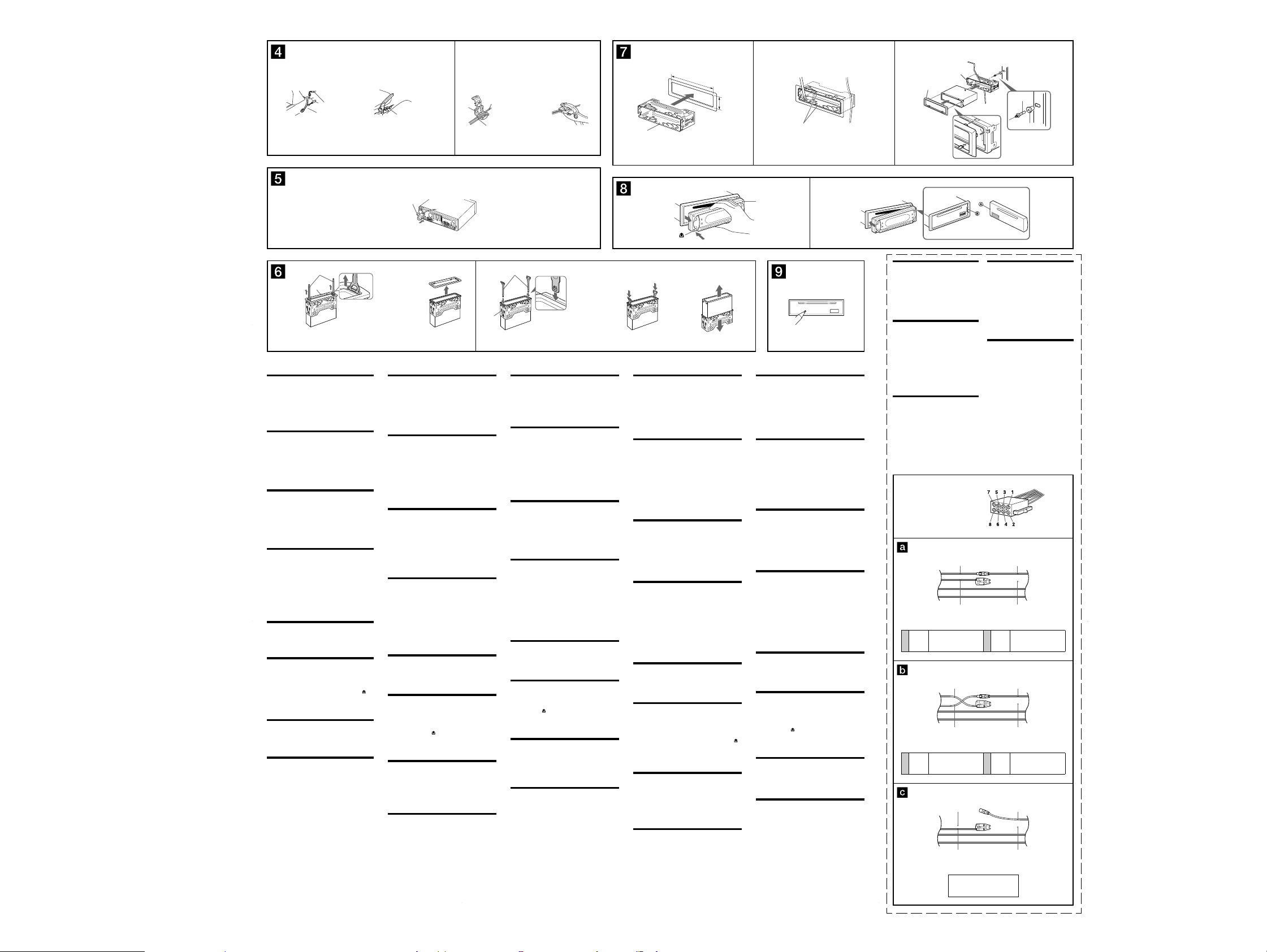
Removing the protection collar and the
bracket (Dz)
Before installing the unit, remove the protection collar ʒ
and the bracket ʌ from the unit.
1
Remove the protection collar ʒ.
ɗ Engage the release keys ʑ together with the protection
collar ʒ.
ɘ Pull out the release keys ʑ to remove the protection collar
ʒ.
2
Remove the bracket ʌ.
ɗ Insert both release keys ʑ together between the unit and
the bracket ʌ until they click.
ɘ Pull down the bracket ʌ, then pull up the unit to separate.
Mounting example (dz)
Installation in the dashboard
Notes
• Bend these claws outward for a tight fi t, if necessary (dz-2).
• Make sure that the 4 catches on the protection collar ʒ are properly engaged
in the slots of the unit (dz-3).
How to detach and attach the front panel
(Ǵ)
Before installing the unit, detach the front panel.
Ǵ-A To detach
Before detaching the front panel, be sure to press ŨƎƅƅũ. Press , and
pull it off towards you.
Ǵ-B To attach
Engage part ʦ of the front panel with part ʧ of the unit, as illustrated,
and push the left side into position until it clicks.
Warning if your car’s ignition has no
ACC position
After turning the ignition off, be sure to press and hold
ŨƎƅƅũ on the unit until the display disappears.
Otherwise, the display does not turn off and this causes battery drain.
RESET button (ǵ)
When the installation and connections are completed, be sure to press
the RESET button with a ballpoint pen, etc., after detaching the front
panel.
j
Sicherheitshinweise
• Wählen Sie den Einbauort sorgfältig so aus, dass das Gerät beim
Fahren nicht hinderlich ist.
• Bauen Sie das Gerät so ein, dass es keinen hohen Temperaturen
(keinem direkten Sonnenlicht, keiner Warmluft von der Heizung),
keinem Staub, keinem Schmutz und keinen starken Vibrationen
ausgesetzt ist.
• Für eine sichere Befestigung verwenden Sie stets die mitgelieferten
Montageteile.
Hinweis zum Montagewinkel
Das Gerät sollte in einem Winkel von weniger als 45° montiert werden.
Anschließen der Parkbremsenleitung
(ǰ)
Die Parkleitung (hellgrün) von ʎ muss unbedingt an die
Parkbremsenschaltleitung angeschlossen werden. Die Montageposition
der Parkbremsenschaltleitung ist von Fahrzeugmodell zu
Fahrzeugmodell unterschiedlich. Weitere Informationen erhalten Sie bei
Ihrem Fahrzeughändler oder Ihrem Sony-Händler.
Das Kontaktstück
Verbinden Sie das Kontaktstück ʐ mit dem Ende der Parkleitung
(hellgrün) von ʎ und der Parkbremsenschaltleitung.
Hinweis
Ist die Parkbremsenschaltleitung zu dünn, verbinden Sie die Parkleitung (hellgrün)
von ʎ direkt mit der Parkbremsenschaltleitung, ohne das Kontaktstück ʐ zu
benutzen.
Wenn Sie eine Digitalverbindung
vornehmen wollen (DZ)
Wenn Sie einen digitalen Verstärker oder ein Audiogerät anschließen
wollen, das mit einem Dolby Digital-Decoder ausgestattet ist, verbinden
Sie das optische Kabel mit DIGITAL OUT an der Rückseite.
Hinweise
• Biegen Sie das optisches Kabel nicht zu stark. Der minimal zulässige
Krümmungsradius beträgt 10 cm. Bei kleinerem Krümmungsradius wird
möglicherweise kein Ton ausgegeben.
• Verwenden Sie unbedingt ein optisches Kabel (nicht mitgeliefert), das für
Autoanlagen von Sony geeignet ist.
• Achten Sie darauf, dass das optisches Kabel nicht durch andere Teile
gequetscht oder eingeklemmt wird.
• Die Steckerteile des Anschlusses dürfen unter keinen Umständen verkratzt oder
verschmutzt werden.
Abnehmen der Schutzumrandung und der
Halterung (Dz)
Nehmen Sie vor dem Installieren des Geräts die
Schutzumrandung ʒ und die Halterung ʌ vom Gerät ab.
1
Entfernen Sie die Schutzumrandung ʒ.
ɗ Setzen Sie beide Löseschlüssel ʑ an der Schutzumrandung
ʒ an.
ɘ Ziehen Sie die Schutzumrandung ʒ mithilfe der
Löseschlüssel ʑ heraus.
2
Entfernen Sie die Halterung ʌ.
ɗ Führen Sie beide Löseschlüssel ʑ zwischen dem Gerät und
der Halterung ʌ ein, bis sie mit einem Klicken einrasten.
ɘ Ziehen Sie die Halterung ʌ nach unten und das Gerät nach
oben, um die beiden zu trennen.
Montagebeispiel (dz)
Installation im Armaturenbrett
Hinweise
• Falls erforderlich, biegen Sie diese Klammern für einen sicheren Halt nach
außen (dz-2).
• Achten Sie darauf, die 4 Verriegelungen an der Schutzumrandung ʒ korrekt in
die Aussparungen am Gerät einzusetzen (dz-3).
Abnehmen und Anbringen der Frontplatte
(Ǵ)
Nehmen Sie die Frontplatte vor dem Einbau des Geräts ab.
Ǵ-A Abnehmen
Schalten Sie das Gerät vor dem Abnehmen der Frontplatte unbedingt
mit ŨƎƅƅũ aus. Drücken Sie
Ǵ-B Anbringen
Setzen Sie Teil ʦ der Frontplatte wie abgebildet an Teil ʧ am Gerät an
und drücken Sie dann die linke Seite hinein, bis sie mit einem Klicken
einrastet.
Warnhinweis, wenn die Zündung
Ihres Fahrzeugs nicht über eine
Zubehörposition (ACC oder I) verfügt
Nachdem Sie die Zündung ausgeschaltet haben, halten
Sie am Gerät unbedingt ŨƎƅƅũ gedrückt, bis die Anzeige
ausgeblendet wird.
Andernfalls wird die Anzeige nicht ausgeschaltet und der Autobatterie
wird Strom entzogen.
Taste RESET (ǵ)
Wenn Sie das Gerät eingebaut und alle Anschlüsse vorgenommen haben,
müssen Sie die Frontplatte abnehmen und mit einem Kugelschreiber
oder einem anderen spitzen Gegenstand die Taste RESET drücken.
und ziehen Sie sie auf sich zu heraus.
ʌ
Face the hook inwards.
Der Haken muss nach innen weisen.
Tournez le crochet vers l’intérieur.
Con il gancetto rivolto verso l’interno.
Het haakje moet naar binnen wijzen.
Précautions
• Choisir soigneusement l’emplacement de l’installation afi n que
l’appareil ne gêne pas la conduite normale du véhicule.
• Eviter d’installer l’appareil dans un endroit exposé à de la poussière,
de la saleté, des vibrations violentes ou à des températures élevées,
comme en plein soleil ou à proximité d’un conduit de chauffage.
• Pour garantir un montage sûr, n’utiliser que le matériel fourni.
Réglage de l’angle de montage
Ajuster l’inclinaison à un angle inférieur à 45°.
Raccordement du cordon du frein à main
(ǰ)
Veillez à raccorder le cordon du frein (vert clair) ʎ au cordon du
capteur du frein à main. La position de montage du cordon du capteur
du frein à main varie selon la voiture. Consultez votre concessionnaire
automobile ou votre revendeur Sony le plus proche pour obtenir plus de
détails.
Utilisation de la dérivation
Raccordez la dérivation ʐ à l’extrémité du cordon du frein (vert clair)
ʎ au cordon du capteur du frein à main.
Remarque
Si le cordon du capteur du frein à main est trop fi n, raccordez le cordon du frein
(vert clair) ʎ au cordon du capteur du frein à main directement sans utiliser la
dérivation ʐ.
En cas de raccordement numérique (DZ)
Lorsque vous raccordez un amplifi cateur numérique ou un appareil
audio doté d’un décodeur Dolby digital, raccordez le câble optique à la
prise DIGITAL OUT située sur le panneau arrière.
Remarques
• Ne pliez pas trop le câble optique. S’il est plié selon un arc inférieur à 10 cm de
diamètre, il est possible qu’aucun son ne soit émis.
• Veillez à utiliser un câble optique (non fourni) compatibles avec les systèmes
audio pour automobiles de Sony.
• Vérifi ez que le câble optique n’est pas trop compressé ou gêné de quelque
façon que ce soit par les objets environnants.
• Faites en sorte que les parties du coupleur des connecteurs ne soient jamais
érafl ées ou souillées.
Retrait du tour de protection et du
support (Dz)
Avant d’installer l’appareil, retirez le tour de protection ʒ et
le support ʌ de l’appareil.
1
Enclenchez le tour de protection ʒ.
ɗ Enclenchez les clés de déblocage ʑ simultanément dans le
tour de protection ʒ.
ɘ Tirez sur la clé de déblocage ʑ pour retirer le tour de
protection ʒ.
2
Retirez le support ʌ.
ɗ Insérez les deux clés de déblocage ʑ simultanément entre
l’appareil et le support ʌ jusqu’au déclic indiquant qu’elles
sont en place.
ɘ Tirez le support ʌ vers le bas, puis tirez l’appareil vers le
haut pour les séparer.
Exemple de montage (dz)
Installation dans le tableau de bord
Remarques
• Pliez ces griffes vers l’extérieur pour assurer une prise correcte si nécessaire
(dz-2).
• Assurez-vous que les 4 loquets du tour de protection ʒ sont correctement
insérés dans les fentes de l’appareil (dz-3).
Retrait et fi xation de la façade (Ǵ)
Avant d’installer l’appareil, déposez la façade.
Ǵ-A Pour la retirer
Avant de déposer la façade, n’oubliez pas d’appuyer sur ŨƎƅƅũ.
, puis faites glisser la façade vers vous.
Appuyez ensuite sur
Ǵ-B Pour la fi xer
Fixez la partie ʦ de la façade sur la partie ʧ de l’appareil, tel
qu’illustré, puis poussez sur le côté gauche jusqu’au déclic indiquant
qu’il est en position.
Avertissement au cas où le contact
de votre voiture ne dispose pas d’une
position ACC
Après avoir coupé le moteur, n’oubliez pas de maintenir
la touche ŨƎƅƅũ de l’appareil enfoncée jusqu’à ce que
l’affi chage disparaisse.
Sinon, l’affi chage n’est pas désactivé et la batterie se décharge.
Touche RESET (ǵ)
Une fois que l’installation et les raccordements sont terminés, retirez
la façade et appuyez sur le bouton RESET à l’aide d’un stylo à bille ou
d’un autre objet pointu.
jj
Dashboard
12 3
182 m
m
Armaturenbrett
Tabl eau de bord
Cruscotto
Dashboard
ʌ
ʒ
53 mm
Claws
ʌ
Klammern
Griffes
Morsetti
Klemhaken
AB
(OFF)
Precauzioni
• Scegliere con attenzione la posizione per l’installazione in modo
che l’apparecchio non interferisca con le operazioni di guida del
conducente.
• Evitare di installare l’apparecchio dove sia soggetto ad alte
temperature, come alla luce solare diretta o al getto di aria calda
dell’impianto di riscaldamento, o dove possa essere soggetto a
polvere, sporcizia e vibrazioni eccessive.
• Usare solo il materiale di montaggio in dotazione per un’installazione
stabile e sicura.
Regolazione dell’angolo di montaggio
Regolare l’angolo di montaggio in modo che sia inferiore a 45°.
Collegamento del cavo del freno a mano
(ǰ)
Assicurarsi di collegare il cavo del freno a mano (verde chiaro) di ʎ
al cavo di commutazione del freno a mano dell’auto. La posizione di
montaggio del cavo di commutazione del freno a mano varia in base
all’auto. Per ulteriori informazioni, consultare l’autoconcessionaria di
fi ducia o il più vicino rivenditore Sony.
Uso del dispositivo di accoppiamento
Applicare il dispositivo di accoppiamento ʐ all’estremità del cavo del
freno a mano (verde chiaro) di ʎ e del cavo di commutazione del freno
a mano.
Nota
Se il cavo di commutazione del freno a mano è troppo sottile, collegare
direttamente il cavo del freno a mano (verde chiaro) di ʎ al cavo di
commutazione del freno a mano senza utilizzare il dispositivo di accoppiamento
ʐ.
Collegamento digitale (DZ)
Durante il collegamento a un amplifi catore digitale o a un apparecchio
audio dotato di decodifi catore Dolby Digital, collegare il cavo ottico alla
presa DIGITAL OUT sul pannello posteriore.
Note
• Non piegare eccessivamente il cavo ottico. Se il cavo viene piegato a formare
un cerchio di diametro inferiore a 10 cm, è possibile che l’audio non venga
riprodotto.
• Assicurarsi di utilizzare un cavo ottico (non in dotazione) progettato per le
autoradio Sony.
• Assicurarsi che il cavo ottico non venga compresso in alcun modo da oggetti
circostanti.
• Evitare che le parti di accoppiamento dei connettori vengano graffi ate o
contaminate da sporcizia.
Rimozione della staffa e della cornice di
protezione (Dz)
Prima di installare l’apparecchio, rimuovere la cornice di
protezione ʒ e la staffa ʌ dall’apparecchio.
1
Rimuovere la cornice di protezione ʒ.
ɗ Inserire le chiavette di rilascio ʑ nella cornice di protezione
ʒ.
ɘ Per rimuovere la cornice di protezione ʒ estrarre le
chiavette di rilascio ʑ.
2
Rimuovere la staffa ʌ.
ɗ Inserire contemporaneamente entrambe le chiavette di
rilascio ʑ tra l’apparecchio e la staffa
scattano in posizione.
ɘ Estrarre la staffa ʌ, quindi sollevare l’apparecchio per
rimuoverlo.
Esempio di montaggio (dz)
Installazione nel cruscotto
Note
• Piegare verso l’esterno questi morsetti per un’installazione più sicura, se
necessario (dz-2).
• Assicurarsi che i 4 fermi sulla cornice di protezione ʒ siano correttamente
inseriti negli alloggiamenti dell’apparecchio (dz-3).
Come rimuovere e reinserire il pannello
anteriore (
Ǵ
Prima di installare l’apparecchio rimuovere il pannello
anteriore.
Ǵ-A Per rimuoverlo
Prima di rimuovere il pannello anteriore, premere ŨƎƅƅũ. Premere ,
quindi tirare verso di sé il pannello anteriore.
Ǵ-B Per reinserirlo
Posizionare la sezione ʦ del pannello anteriore sulla sezione ʧ
dell’apparecchio, come illustrato, quindi premere il lato sinistro fi no a
farlo scattare in posizione.
Avvertenza relativa all’installazione
su un’auto sprovvista della posizione
ACC (accessoria) sul blocchetto di
accensione
Dopo avere spento il motore, assicurarsi di tenere premuto
ŨƎƅƅũ sull’apparecchio fi nché il display non scompare.
Diversamente, il display non viene disattivato e questo potrebbe causare
lo scaricamento della batteria.
Tasto RESET (ǵ)
Una volta completate le procedure di installazione e i collegamenti,
accertarsi di premere il tasto RESET con una penna a sfera o un oggetto
simile dopo avere rimosso il pannello anteriore.
)
ʌ
fi no a che non
Voorzorgsmaatregelen
• Kies de installatieplaats zorgvuldig zodat het apparaat de bestuurder
niet hindert tijdens het rijden.
• Installeer het apparaat niet op plaatsen waar het blootgesteld wordt aan
hoge temperaturen, b.v. in direct zonlicht of bij de warme luchtstroom
van de autoverwarming, aan sterke trillingen, of waar het in contact
komt met veel stof of vuil.
• Gebruik voor het veilig en stevig monteren van het apparaat
uitsluitend de bijgeleverde montage-onderdelen.
Maximale montagehoek
Installeer het apparaat nooit onder een hoek van meer dan 45° met het
horizontale vlak.
Parkeerremkabel aansluiten (ǰ)
Sluit de parkeerremkabel (lichtgroen) van ʎ aan op het schakelsnoer
van de parkeerrem. De plaats waar het schakelsnoer van de parkeerrem
moet worden geplaatst, is afhankelijk van de auto. Raadpleeg de
autohandelaar of de dichtstbijzijnde Sony-handelaar voor meer
informatie.
Het verbindingselement gebruiken
Maak het verbindingselement ʐ vast aan het uiteinde van de
parkeerremkabel (lichtgroen) van ʎ en het schakelsnoer van de
parkeerrem.
Opmerking
Als het schakelsnoer van de parkeerrem te dun is, verbindt u de parkeerremkabel
(lichtgroen) van ʎ rechtstreeks met het schakelsnoer van de parkeerrem zonder
het verbindingselement ʐ te gebruiken.
Een digitale aansluiting maken (DZ)
Als u het apparaat aansluit op een digitale versterker of audioapparaat
met een Dolby digital decoder, sluit u de optische kabel aan op
DIGITAL OUT op het achterpaneel.
Opmerkingen
• Buig de optische kabel niet te veel. Als de kabel in een boog met een diameter
van minder dan 10 cm wordt gebogen, wordt er wellicht geen geluid meer
geproduceerd.
• Zorg ervoor dat u een optische kabel gebruikt (niet bijgeleverd) die ontworpen
zijn voor car audiosystemen van Sony.
• Controleer of de optische kabel niet bekneld of belemmerd wordt door
omringende objecten.
• Zorg ervoor dat de koppelstukken van de aansluitingen nooit bekrast worden of
vervuild raken.
De beschermende rand en de beugel
verwijderen (Dz)
Voordat u het apparaat gaat installeren, moet u de
beschermende rand ʒ en de beugel ʌ verwijderen van het
apparaat.
1
Verwijder de beschermende rand ʒ.
ɗ Bevestig de ontgrendelingssleutels ʑ op de beschermende
rand ʒ.
ɘ Trek de ontgrendelingssleutels ʑ naar u toe om de
beschermende rand ʒ te verwijderen.
2
Verwijder de beugel ʌ.
ɗ Plaats de ontgrendelingssleutels ʑ tussen het apparaat en de
beugel
ʌ
tot deze vastklikken.
ɘ Trek de beugel
ʌ
omlaag en trek het apparaat omhoog om
deze van elkaar te scheiden.
Montagevoorbeeld (dz)
Montage in het dashboard
Opmerkingen
• Indien nodig kunt u deze klemhaken ombuigen voor een steviger bevestiging
(dz-2).
• De 4 grepen op de beschermende rand ʒ moeten goed in de sleuven van het
apparaat zijn geplaatst (dz-3).
Het voorpaneel verwijderen en
bevestigen
(Ǵ)
Verwijder het voorpaneel voordat u begint met de installatie.
Ǵ-A Verwijderen
Voordat u het voorpaneel verwijdert, moet u eerst op ŨƎƅƅũ drukken.
Druk vervolgens op de
Ǵ-B Bevestigen
Bevestig deel ʦ van het voorpaneel op deel ʧ van het apparaat, zoals
in de afbeelding wordt weergegeven, en druk op de linkerkant van het
voorpaneel tot dit vastklikt.
Waarschuwing als het contactslot van de
auto geen ACC-positie heeft
Als de motor is uitgeschakeld, moet u op ŨƎƅƅũ drukken en
deze toets ingedrukt houden tot de weergave verdwijnt.
Als u dit niet doet, wordt de weergave niet uitgeschakeld en raakt de
accu uitgeput.
RESET-toets (ǵ)
Als u de installatie en aansluitingen hebt voltooid, moet u met een
puntig voorwerp, zoals de punt van een balpen, op RESET drukken
nadat u het voorpaneel hebt verwijderd.
toets en trek het voorpaneel naar u toe.
Power connection diagram
Auxiliary power connector may vary depending on the
car. Check your car’s auxiliary power connector diagram
to make sure the connections match correctly. There are
three basic types (illustrated below). You may need to
switch the positions of the red and yellow leads in the car
stereo’s power connecting lead.
After matching the connections and switched power
supply leads correctly, connect the unit to the car’s
power supply. If you have any questions and problems
connecting your unit that are not covered in this manual,
please consult the car dealer.
Stromanschlussdiagramm
Der Hilfsstromanschluss kann je nach Fahrzeugtyp
unterschiedlich sein. Sehen Sie im Hilfsstromanschlussdiagramm für Ihr Fahrzeug nach, wie die
Verbindung ordnungsgemäß vorgenommen werden muss.
Es gibt, wie unten abgebildet, drei grundlegende Typen.
Sie müssen möglicherweise die rote und gelbe Leitung
des Stromversorgungskabels der Autostereoanlage
vertauschen.
Stellen Sie die Anschlüsse her, schließen Sie die
geschalteten Stromversorgungsleitungen richtig an und
verbinden Sie dann das Gerät mit der Stromversorgung
Ihres Fahrzeugs. Wenn beim Anschließen des
Geräts Fragen oder Probleme auftreten, die in dieser
Bedienungsanleitung nicht erläutert werden, wenden Sie
sich bitte an den Autohändler.
Schéma de raccordement
d’alimentation
Le connecteur d’alimentation auxiliaire peut varier
suivant le type de voiture. Vérifi ez le schéma du
connecteur d’alimentation auxiliaire de votre voiture
pour vous assurer que les connexions correspondent. Il
en existe trois types de base (illustrés ci-dessous). Il se
peut que vous deviez commuter la position des fi l rouge
et jaune du cordon d’alimentation de l’autoradio.
Après avoir établi les connexions et commuté
correctement les fi ls d’alimentation, raccordez l’appareil
à l’alimentation de la voiture. Si vous avez des questions
ou des diffi cultés à propos de cet appareil qui ne sont pas
abordées dans le présent mode d’emploi, consultez votre
concessionnaire automobile.
Auxiliary power connector
Hilfsstromanschluss
Connecteur d’alimentation auxiliaire
Connettore di alimentazione accessoria
Hulpvoedingsaansluiting
Yell ow
continuous power supply
Gelb
permanente Stromversorgung
4
Jaune
alimentation continue
Giallo
alimentazione continua
Geel
continu voeding
Red
Rot
Rouge
Rosso
Rood
Yell ow
Gelb
Jaune
Giallo
Yell ow
Gelb
4
Jaune
Giallo
Geel
Geel
switched power supply
geschaltete Stromversorgung
alimentation commutée
alimentazione commutata
geschakelde voeding
Fahrzeug ohne Zubehörposition (ACC)
Diagramma dei collegamenti di
alimentazione
Il connettore di alimentazione accessoria può variare a
seconda della macchina. Controllare il diagramma del
connettore di alimentazione accessoria della macchina
per essere sicuri che i collegamenti corrispondano
correttamente. Vi sono tre tipi di base (illustrazione
sotto). Potrà essere necessario cambiare le posizioni dei
fi li rosso e giallo nel cavo di alimentazione dello stereo
della macchina.
Dopo aver fatto corrispondere i collegamenti e
aver commutato i cavi di alimentazione, collegare
l’apparecchio all’alimentazione della macchina. Se si
hanno domande o se sorgono problemi che non sono
stati trattati nel manuale nel collegare l’apparecchio,
contattare l’autoconcessionario.
Voedingsaansluitschema
De hulpvoedingsaansluiting kan verschillen afhankelijk
van de auto. Controleer het voedingsaansluitschema
dat bij dit apparaat wordt geleverd om te zien of de
aansluitingen kloppen. Er zijn drie basistypes (zie
afbeelding hieronder). Het is mogelijk dat u de posities
van de rode en gele kabels in het aansluitsnoer van het
car audiosysteem moet omwisselen.
Als de aansluitingen en geschakelde voedingskabels
kloppen, sluit u het apparaat aan op de voeding van de
auto. Indien u nog vragen of problemen hebt in verband
met het aansluiten van het apparaat die niet in deze
handleiding vermeld staan, moet u de autohandelaar
raadplegen.
Red
Rot
Rouge
Rosso
Rood
Yell ow
Gelb
Jaune
Giallo
Geel
7
Rouge
Rosso
7
Rouge
Rosso
Red
Rot
Rouge
Rosso
Rood
Yell ow
Gelb
Jaune
Giallo
Geel
the car without ACC position
Véhicule sans position ACC
Auto priva della posizione ACC
Auto zonder ACC-positie
Red
Rot
Rood
Red
Rot
Rood
Fire wall
Motorraumtrennwand
Paroi ignifuge
Parete tagliafi amma
Brandschot
ʓ
ʔ
Red
Rot
Rouge
Rosso
Rood
Yell ow
Gelb
Jaune
Giallo
Geel
switched power supply
geschaltete Stromversorgung
alimentation commutée
alimentazione commutata
geschakelde voeding
Red
Rot
Rouge
Rosso
Rood
Yell ow
Gelb
Jaune
Giallo
Geel
continuous power supply
permanente Stromversorgung
alimentation continue
alimentazione continua
continu voeding
Red
Rot
Rouge
Rosso
Rood
Yell ow
Gelb
Jaune
Giallo
Geel
(AEP, UK models)
99

MEX-R1
)
SECTION 3
DISASSEMBLY
Note: Follow the disassembly procedure in the numerical order given.
• This set can be disassembled in the order shown below.
3-1. DISASSEMBLY FLOW
SET (GENERAL SECTION)
3-2. SUB PANEL COMPLETE ASSY
(Page 10)
3-3. DVD MECHANISM DECK (MG-612-187)
(Page 10)
3-5. CHASSIS (T) SUB ASSY
(Page 11)
3-6. ROLLER ARM ASSY
(Page 12)
3-4. MAIN BOARD, DC FAN (25X25) (M901)
(Page 11)
3-9. LE MOTOR ASSY (LOADING) (M3)
(Page 13)
3-10. SERVO BOARD
(Page 14)
3-2. SUB PANEL COMPLETE ASSY
2
two bosses
5
two claws
1
screw
(PTT 2.6
5
two claws
x
3
6)
cover
2
two bosses
3-7. CHASSIS (OP-DVD) COMPLETE ASSY
(Page 12)
3-8. CHASSIS (OP-DVD) SUB ASSY
(Page 13)
SET (FRONT PANEL SECTION)
3-11. FRONT BACK PANEL (LCD)
(Page 14)
3-12. BASE BOARD
(Page 15)
3-13. DISPLAY SECTION
(Page 15)
4
two
screws
x
(PTT 2.6
6)
3-3. DVD MECHANISM DECK (MG-612-187)
7
dust protection sheet
8
DVD mechanism deck
(MG-612-187)
2
connector
(CN3)
6
sub panel complete assy
4
two
screws
(PTT 2.6
x
6
bracket (CD)
1
screw
(PTT 2.6
6)
x
6)
3-14. BRACKET (DISPLAY)
(Page 16)
3-15. SPRING (S)
(Page 16)
5
shield
(mecha)
3
two
screws
(P 1.7
1010
x
2.5)
1
screw
(PTT 2.6
x
6
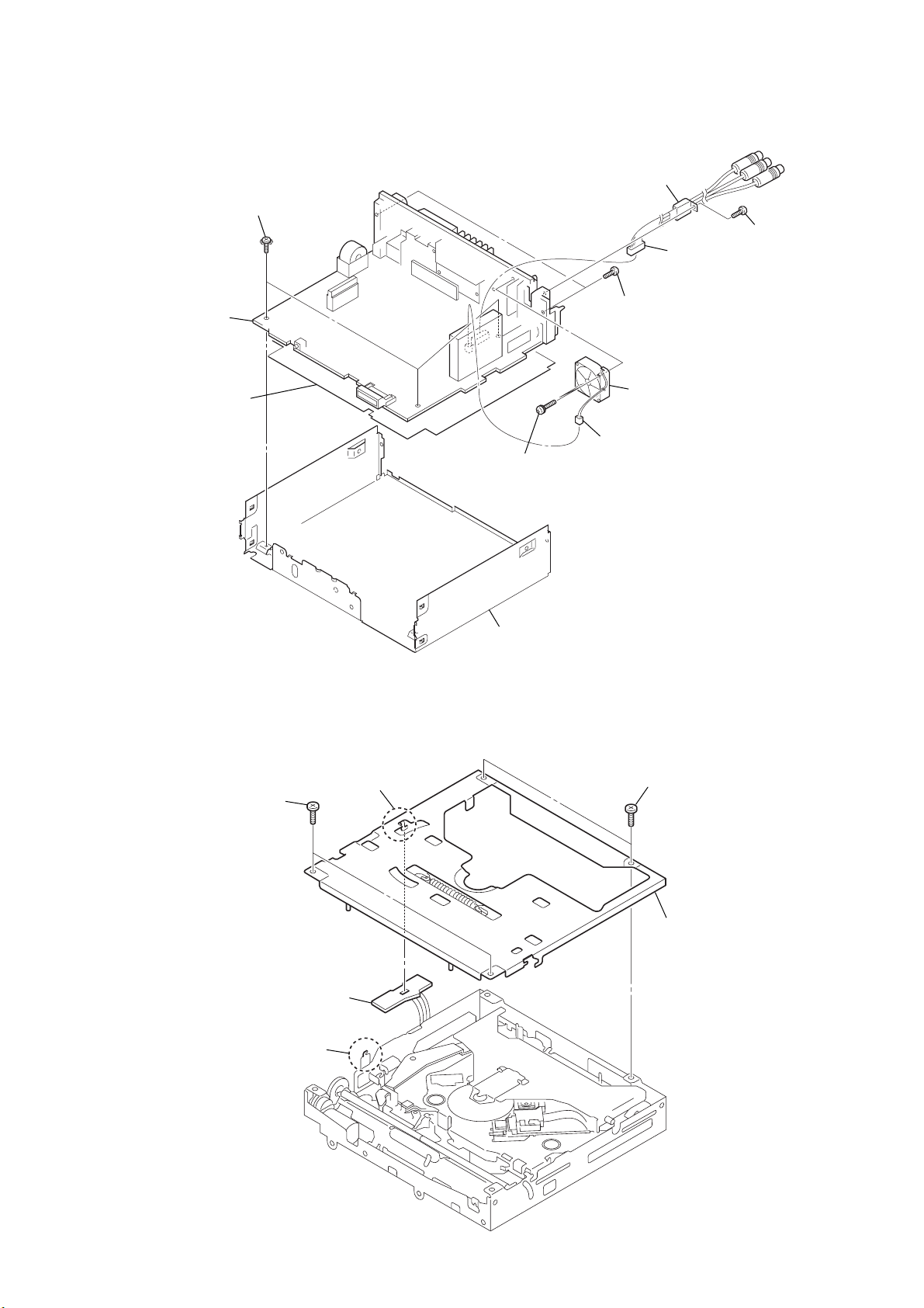
3-4. MAIN BOARD, DC FAN (25X25) (M901)
y
8
three ground point
(PTT 2.6
9
MAIN board
q;
insulating sheet
x
screws
6)
1
two
screws
(PS 2.6
6
(rear out)
2
(CN901)
x
14)
connection cord
4
connector
(CN701)
7
two
screws
(PTT 2.6
3
connector
DC fan
(M901)
x
(25
MEX-R1
5
screw
(PTT 2.6
8)
x
25)
x
8)
3-5. CHASSIS (T) SUB ASSY
1
two
screws
(P 1.7
x
2.2)
4
SENSOR borad
2
claw
3
claw
qa
chassis (CD)
1
two
screws
(P 1.7
x
2.2)
5
chassis (T) sub ass
11
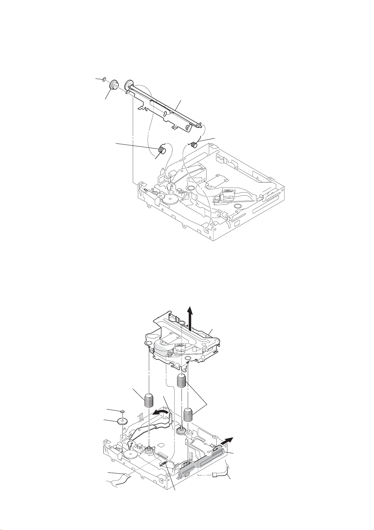
MEX-R1
y
3-6. ROLLER ARM ASSY
3
washer
(1.1-2.5)
4
gear (RA1)
1
spring (RAL)
5
roller arm assy
2
spring (RAR)
3-7. CHASSIS (OP-DVD) COMPLETE ASSY
q;
compression spring (damper)
4
washer
5
gear (LE1)
lever (D)
6
8
qa
chassis (OP-DVD) complete ass
9
two
compression springs (damper)
7
slider (R)
12
2
motor flexible board
(CN1)
3
tension spring (KF)
1
OP flexible board
(CN2)
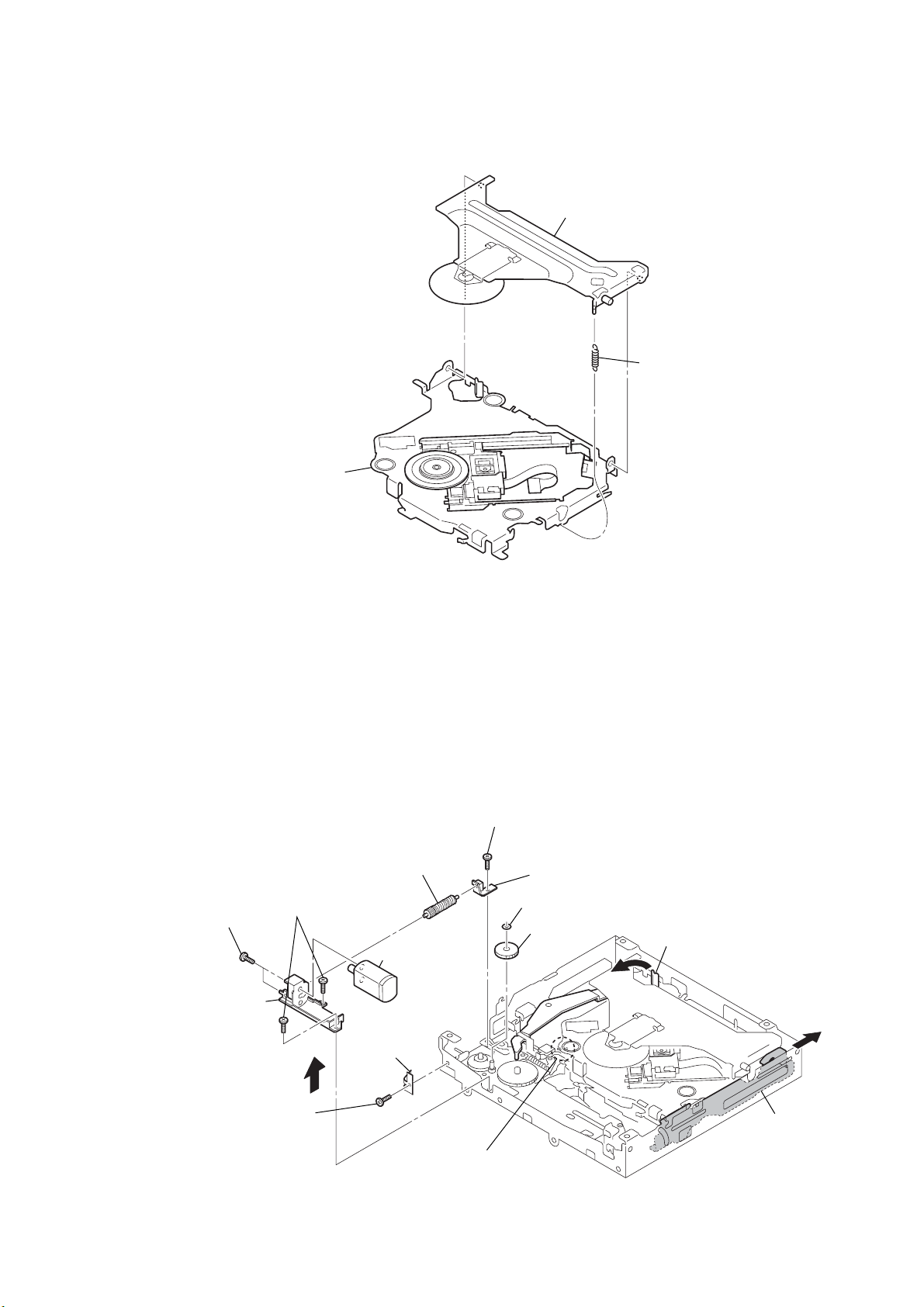
3-8. CHASSIS (OP-DVD) SUB ASSY
)
3
chassis (OP-DVD) sub assy
2
chucking arm sub assy
1
tension coil spring (CHKG
MEX-R1
3-9. LE MOTOR ASSY (LOADING) (M3)
q;
gear (LE) assy
qd
two
(M 1.4)
qg
bracket (LEM-N)
screws
6
(P 1.7
screw
qa
(M 1.7
x
2.2)
two
qs
screws
x
2.5)
7
qf
leaf spring
(LE)
1
8
screw
(M 1.7
LE motor assy
(loading) (M3)
Remove the two solders of the
LE motor assy lead wires.
2
3
x
9
washer
2.5)
bearing (LEB-N)
gear (LE1)
4
lever (D)
5
slider (R)
13
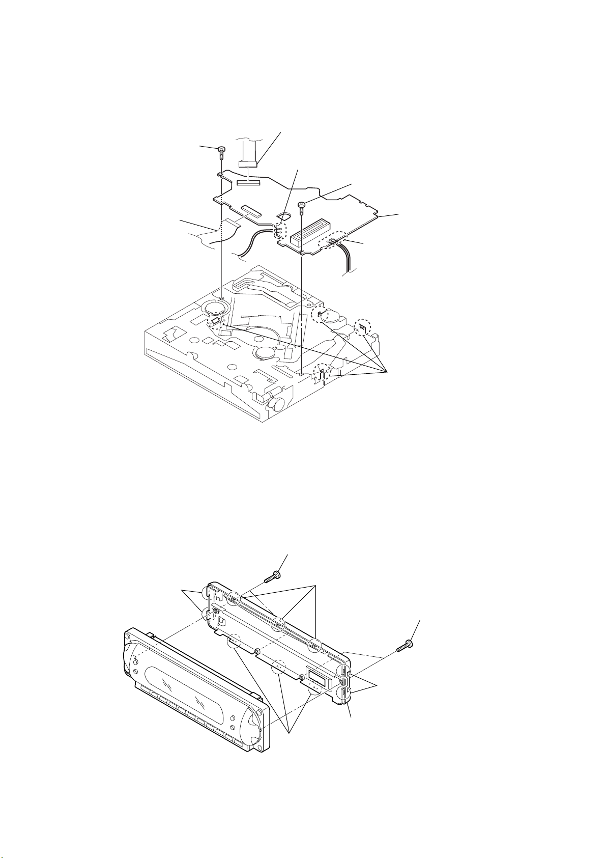
MEX-R1
s
3-10. SERVO BOARD
3
motor flexible board
(CN1)
4
screw
(P 1.7
x
2.2)
2
OP flexible board
(CN2)
1
Remove the two solders.
4
screw
x
(P 1.7
2.2)
6
SERVO board
1
Remove the three solders.
3-11. FRONT BACK PANEL (LCD)
2
two claws
1
two
(P 2
screws
x
8)
2
three claws
5
four claws
1
two
(P 2
screw
x
8)
14
2
three claws
2
two claws
3
front back panel (LCD)

3-12. BASE BOARD
flexible flat (6 core) cable
2
(CN903)
1
4
BASE board
3
flexible flat (12 core) cable
(CN902)
MEX-R1
3-13. DISPLAY SECTION
Note for assembly
After installing to the front panel assy,
make sure the spring is not off
from the dowel.
front panel assy
3
4
display section
2
two
screws
(B P-TITE M2)
Note for assembly
After installing to the front panel assy,
make sure the spring is not off from the dowel.
1
Raise the preset assy up in the arrowed direction.
15
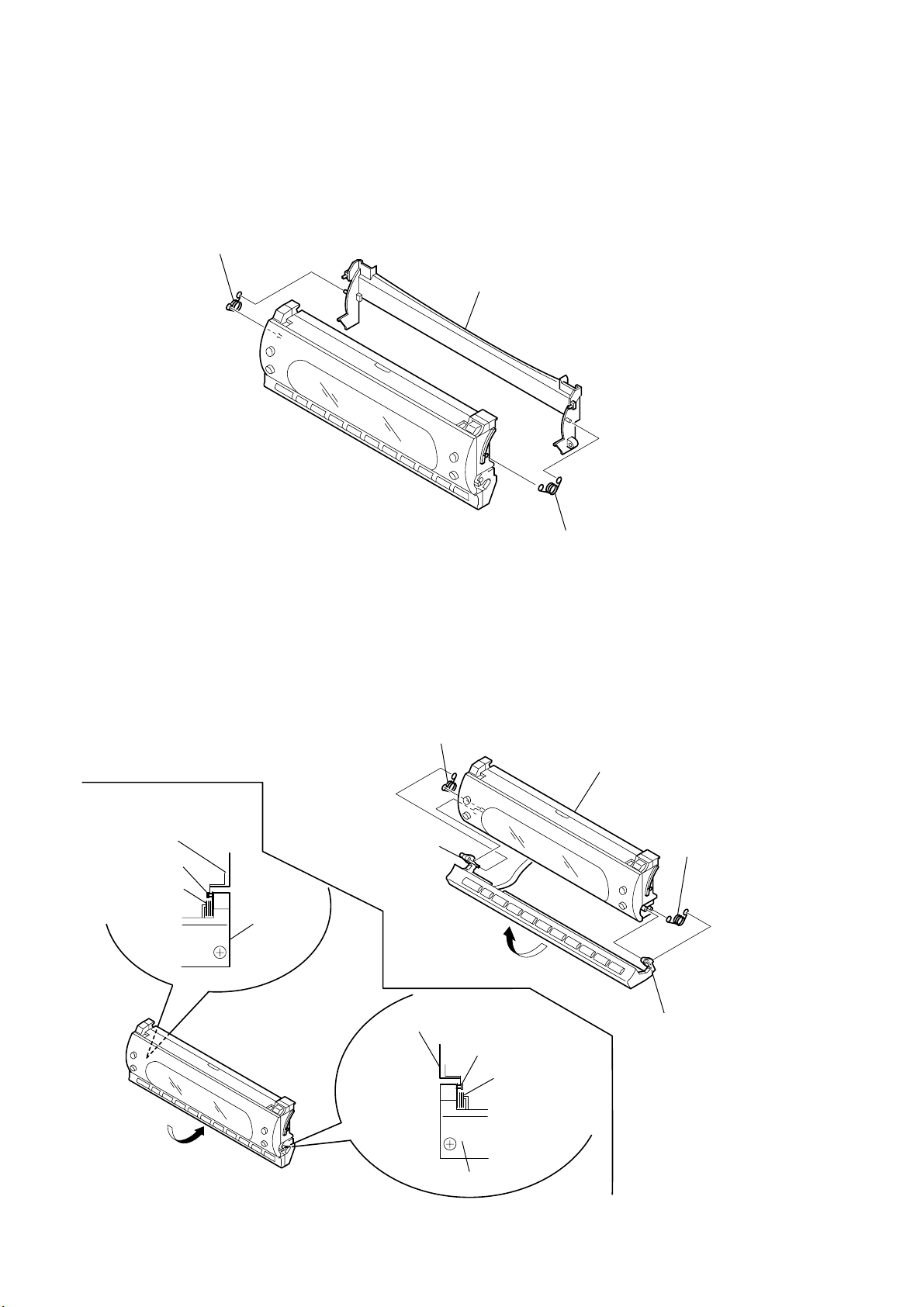
MEX-R1
)
3-14. BRACKET (DISPLAY)
2
spring (M)
3
bracket (display)
3-15. SPRING (S)
Note for assembly
display (SV) assy
spring (S)
dowel
3
Take off the spring from
the dowel on preset assy side.
preset assy
Make sure the spring
is not off from the dowel.
5
spring (S)
1
Raise the preset assy
up in the arrowed direction.
display (SV) assy
dowel
spring (S)
1
spring (M
display (SV) assy
2
the dowel on preset assy side.
4
spring (S)
Take off the spring from
16
Put preset assy back
in the arrowed direction.
preset assy
Make sure the spring is not off from the dowel.
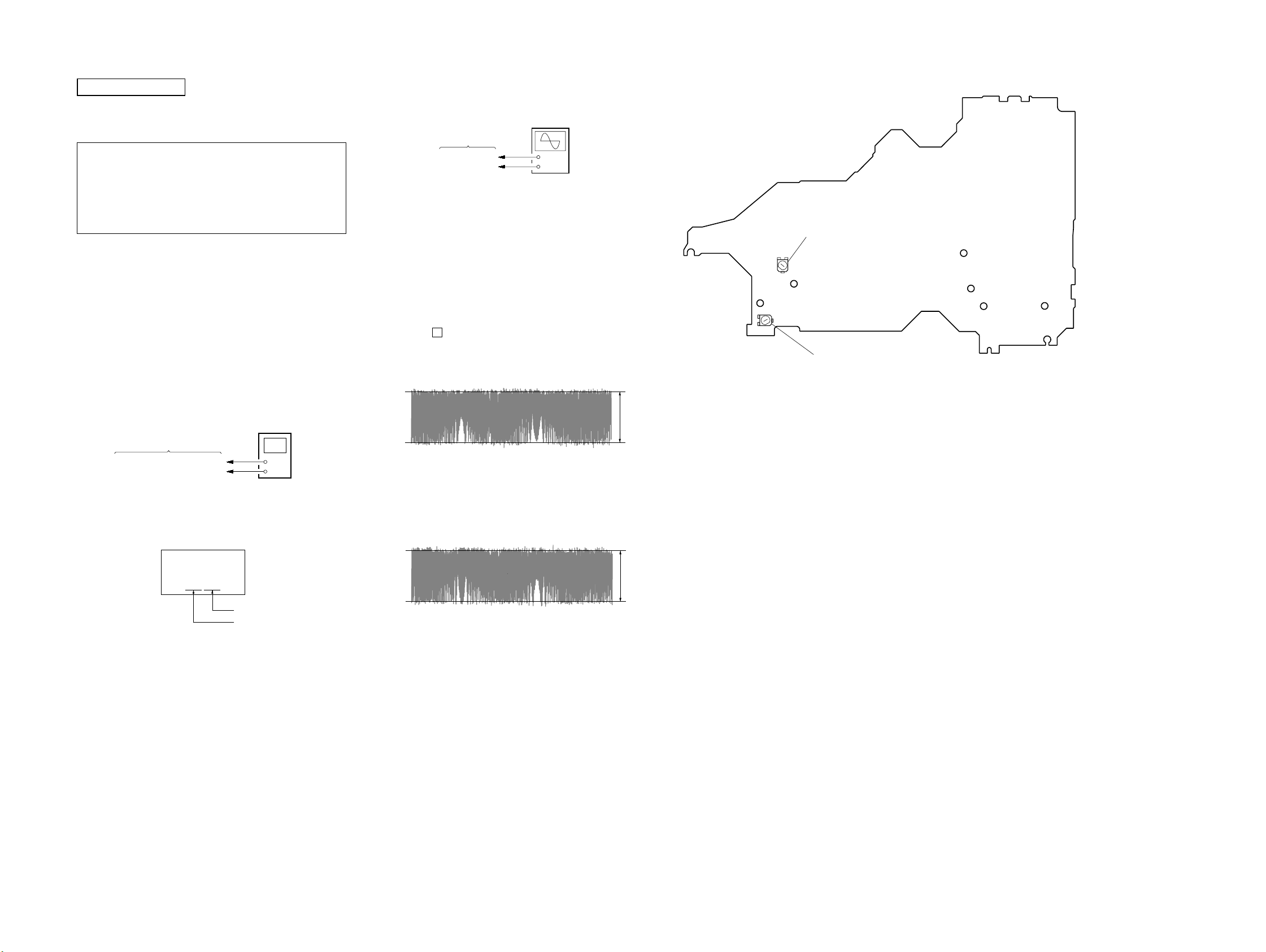
SECTION 4
r
e
e
p
p
ELECTRICAL ADJUSTMENTS
MEX-R1
SERVO SECTION
If any of the following parts was replaced, perform the “IOP Check”
and “E, F Signal Offset Adjustment” as mentioned below.
• Optical pick-up block (chassis (OP-DVD) complete
assy or chassis (OP-DVD) sub assy)
• Mounted SERVO board
• SERVO board: IC4
R29, R30, R40, R41, R43, R44
R53, R54, R57, R58, R65, R69
RV1, RV2
Precaution
Use the following tools and measuring devices.
• Extension jig (Part No. : J-2502-094-1) between the SERVO
board and the MAIN board
• DVD test disc TDV-540C (Part No. : 7-819-098-53)
• CD test disc PATD-012 (Part No. : 4-225-203-01)
• Digital voltmeter
• Oscilloscope
• Accessory remote commander
RM-X702 (except AEP and UK models)
RM-X703 (AEP and UK models)
IOP CHECK
Connection:
digital voltmete
SERVO board
TP (IOPDVD), TP (IOPCD)
TP (A5V)
Procedure:
1. Check the IOP value of DVD and CD by label on the optical
pick-up.
Optical Pick-up Label:
+
–
E, F SIGNAL OFFSET ADJUSTMENTS
Connection:
oscilloscop
(DC range)
SERVO board
TP (E), TP (F)
TP (AGND)
Procedure:
1. Connect an oscilloscope to TP (E) and TP (AGND) on the
SERVO board.
2. In the standby status, press the [4] key of the remote
commander.
3. Press the [5] key of the remote commander.
4. Press the [7] key of the remote commander for more than two
seconds.
5. When the test mode is selected, a peep sound is generated and
the LCD display becomes 6-digit hexadecimal number
indication.
(*1)
6. Playback the CD test disc (PATD-012).
7. Press the P key of the remote commander.
8. Adjust the RV2 on the SERVO board so that waveform level
of oscilloscope becomes between 2.75 and 2.80 V as follo ws.
E Signal Waveform:
0 V
9. Connect an oscilloscope to TP (F) and TP (AGND) on the
SERVO board.
10. Adjust the RV1 on the SERVO board so that waveform level
of oscilloscope becomes between 2.75 and 2.80 V as follo ws.
F Signal Waveform:
+
–
level: 2.75 to 2.80 Vp-
Adjustments Location:
– SERVO Board (Side B) –
E Signal Offset Adjustment
TP (F)
F Signal Offset Adjustment
RV2
TP (E)
TP (IOPCD)
TP (IOPDVD)
TP (AGND)
TP (A5V)
RV1
KHS-340B
*******
$$$###
CD IOP value
DVD IOP valu
2. Connect a digital voltmeter to TP (IOPDVD) and TP (A5V)
on the SERVO board.
3. Playback the DVD test disc (TDV-540C), and make a note of
the value of digital voltmeter.
4. Divide the measured voltage value by 16.5, and con vert it into
current value.
5. Check that the calculated value is within ±6 mA to the IOP
value given on the label.
6. Connect a digital voltmeter to TP (IOPCD) and TP (A5V) on
the SERVO board.
7. Playback the CD test disc (PATD-012), and make a note of
the value of digital voltmeter.
8. Divide the measured voltage value by 16.5, and con vert it into
current value.
9. Check that the calculated value is within ±6 mA to the IOP
value given on the label.
0 V
level: 2.75 to 2.80 Vp-
11. Press the [RESET] button on the MAIN board, release the test
mode.
*1) In the TEST mode, if any abnormality occurred in the operation, for
instance, by pressing a wrong key , press the [RESET] button on the
MAIN board to reset the operation once, and then retry the operation.
1717
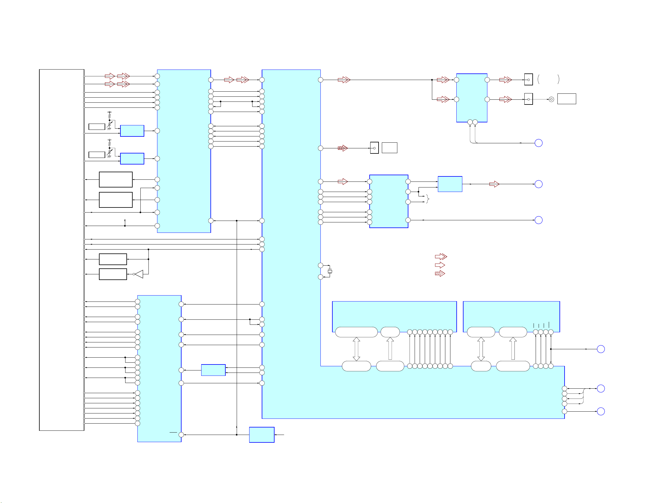
MEX-R1
5-1. BLOCK DIAGRAM – SERVO Section –
OPTICAL PICK-UP BLOCK
KHS-340B
LD DVD
LD CD
RFP
RFN
SECTION 5
DIAGRAMS
DVD
ANALOG FRONT-END
IC1
RFIP
2
RFIN
1
MA
A
B
C
D
A +5V
RV2
E SIGNAL
E
A +5V
RV1
F SIGNAL
F
AUTOMATIC POWER
CONTROL (FOR DVD)
AUTOMATIC POWER
CONTROL (FOR CD)
PD
VC
COMPARATOR
COMPARATOR
Q1
Q5
IC4 (1/2)
IC4 (2/2)
VC
54
MB
53
MC
52
MD
51
TRP
58
TRN
57
LDDVD
44
PDDVD
43
LDCD
41
PDCD
40
VREF
46
RFAC
TEIN
SIGM
SDATA
SCLK
SDEN
DFT
MIRR
XRST
11
PE
38
FE
39
TE
36
33
35
30
29
31
26
25
28
14
32
29
30
13
33
10
214
7
8
6
9
RF AC
PI
FE
TE
TZC
AMPMNT
SDT
SCK
SEN
DEFCT
MIRR
RF_RST
DVD PROCESSOR
IC6
PA0
SPDIFOUT0
DOWNMIX
DACCLK
LRCLK
DOCLK
MD
MC
ML
VIDEO SELECT,
75 OHM DRIVER
IC701
VSAG
AMP
IC303
VIN
4
CYIN
12
CYOUT
MUTE13MUTE2
15
MUTE1
MUTE2
30
25
129
CN601
1
D/A CONVERTER
DATA
2
SCK
16
LRCK
3
BCK
1
MD
13
MC
14
ML
15
DIGITAL
OUTPUT
IC302
OUTL
VCOM
OUTR
ZEROR
7
10
8
11
DIFFERENCIAL
R-CH
203
202
206
205
207
143
144
145
CN301 (1/3)
15
CN701 (1/2)
5
MUTE1,
MUTE2
DVD-L
Z_MUTE
FRONT
VIDEO OUT
A
B
C
VIDEO OUT
(Page 19)
(Page 19)
(Page 19)
REAR
LIMIT SWITCH
GAIN SW
MODE SW
VR DVD
VR CD
FCS+
FCS–
TRK+
TRK–
SLED MOTOR A+
SLED MOTOR A–
SLED MOTOR B+
SLED MOTOR B–
COIL U
COIL V
COIL W
HALL U+ (H1+)
HALL U– (H1–)
HALL V+ (H2+)
HALL V– (H2–)
HALL W+ (H3+)
HALL W– (H3–)
HALL_BAIS–
DVD ON SWITCH
Q4
CD ON SWITCH
Q3
Q2
COIL/MOTOR DRIVE
VO1+
35
VO1–
34
VO2–
31
VO2+
32
VO3+
29
VO3–
28
VO4+
26
VO4–
25
U1
10
U2
11
V1
6
V2
7
W1
2
W2
3
HU+
14
HU–
15
HV+
16
HV–
17
HW+
18
HW–
19
HB
13
IC2
IN1
IN2
IN3
IN4
INSP
STBY
LMT_SW
47
210
215
GAINSW
CD/DVD
• R-ch is omitted due to same as L-ch.
• SIGNAL PATH
: DVD/CD (VIDEO)
RAS
RAS
CAS
WE
17
16
39
84
86
87
CAS
DWE
: DVD/CD (AUDIO)
: OPTICAL OUTPUT
DQMH
15
88
DQMU
DQML
DQML
DQ7 – DQ0
44, 42, 40, 38,
35, 33, 31, 29
167 – 164,
162 – 159
HDATA0 – HDATA7
FLASH MEMORY
IC10
A0 – A16,
DQ15_A-1
1 – 10,
16 – 25, 48, 45
148 – 158, 170,
172 – 179, 181, 182
HADR10 – HADR31
WE
OE
WP_ACC
WS
RST
28
14
12
RESET
168
169
125
RS
WP
RESET
RXD
TXD
CTS
RTS
AMUTE
RXD
198
TXD
197
CTS
196
RTS
195
142
AMUTE
D
E
F
(Page 19)
(Page 20)
(Page 19)
11
180
XO
5655XI
42
43
44
45
46
FG
47
24
COMPARATOR
IC11
FSCON
39
TSCON
41
SE
31
STA
40
STB
38
SPWM1
3
SPWM2
4
FG
5
RESET SIGNAL
GENERATOR
IC3
D +1.5V
X1
36.864MHz
DQ0 – DQ15
2, 4, 5, 7, 8, 10, 11, 13, 42,
44, 45, 47, 48, 50, 51, 53
89 – 92, 95 – 98,
101 – 108
MD0 – MD15
SD-RAM
IC7
A0 – A11
22 – 26,
29 – 35
63 – 68,
71 – 74, 76, 78
MA0 – MA11
20
77
BA0
21
75
MBA0
BA1
38
85
MBA1
CLK
19
81
MCLK
CS
18
83
DCS
MEX-R1
1818
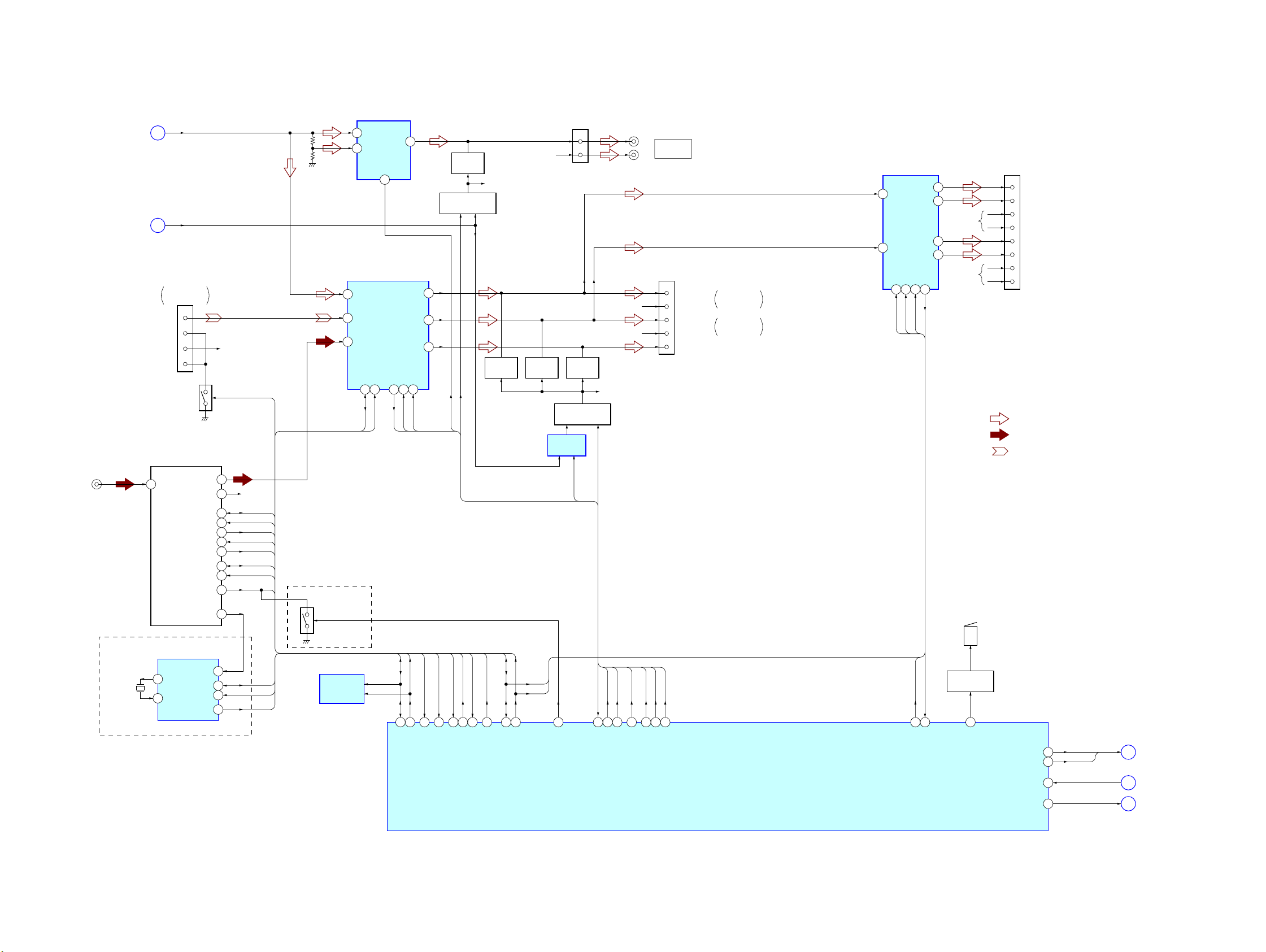
5-2. BLOCK DIAGRAM – AUDIO Section –
DVD-L
(Page 18)
(Page 18)
J201
(ANTENNA IN)
B
AMUTE
F
CN301
(2/3)
BUS AUDIO IN
(AUX IN)
AUX L
AUX LGND
AUX R
AUX RGND
GND SWITCH
Q301
FM/AM TUNER PACK
TUX201
1 ANT
MUTE-CONDITION
11
12
13
14
TU_SDA
TU_SCL
S_METER
TU_MUTE
E2P_SDA
E2P_SCL
QUALITY
RDS
R-CH
BUS_AUX
L
4
R
3
R-CH
14
13
6
7
8
17
16
5
9
SDA
SCL
VSM
TU MUTE
MUTE CON
TRDA
TRCL
QUALITY
42
4
40
(AEP, UK)
NS DET DISCHARGE
SWITCH
Q202
GAIN CONTROL
IC304
IN1B
6
OUTB
IN2B
7
CNT1
2
INPUT SELECT,
ELECTRICAL VOLUME
IC301
13
SCL
OUTLF
OUTLR
OUTSW
SAOUT16SAIN14MUTE
SADATA
SACLK
MD L
PDL+
AML
SDA12SCL
SDA
11
15
VMUTE
MUTING CONTROL
25
24
17
G_DOWN
MUTING
Q311
Q309, 310
REAR ATT
R-CH
MUTING
Q302
R-CH
MUTING
Q304
CN701 (2/2)
3
1
MUTING
Q306
MUTING CONTROL
Q307, 308
SWITCHING
IC305
MUTE_SEL
ATT
R-CH
R-CH
R-CH
(L)
(R)
CN301 (3/3)
ZxZ REAR
AUDIO OUT
1
FRONT LCH
3
FRONT RCH
5
REAR LCH
7
REAR RCH
9
SUB (SUB OUT (MONO))
FRONT AUDIO
OUT
REAR AUDIO
OUT
POWER AMP
FL IN
12
RL IN
11
IC306 (1/2)
FL+
FL–
RL+
RL–
SDA2SCL4STB22DIAG
25
SDA
SCL
STB
DIAG
MEX-R1
CN801 (2/2)
5
3
R-CH
9
7
R-CH
BZ801
1
FL+
9
FL–
4
FR+
12
FR–
2
RL+
10
RL–
3
RR+
11
RR–
• R-ch is omitted due to same as L-ch.
• SIGNAL PATH
: DVD/CD (AUDIO)
: TUNER
: AUX IN
MEX-R1
X201
4.332MHz
(AEP, UK)
RDS DECODER
4
OSCO
5
OSCI
IC201
MPX
SDA
SCL
DAVN
SCL
DAVN
51
DAVN
QUALITY
41
39
QUALITY
VSM
VSM
TU MUTE
MUTE CON
3
50
TUNATT
16
9
10
8
SDA
SCL
DAVN
EEPROM
IC504
TRDA
1
EESIO
TRCL
2
EECKO
BUS_AUX
10
BUS_AUX
TUN_ATTIN
SDA
32
31
I2CSIO
I2CCKO
SDA
SCL
4
NSMASK
SACLK
SADATA
30
44
SA_IN
VMUTE
15
SA_CLK
ATT
G_DOWN
REAR ATT
MUTE_SEL
28
16
11
14
VOLATT
G_DOWN
REAR ATT
MUTE_SEL
SYSTEM CONTROLLER
IC501 (1/2)
ATT
23
STB
STB
DIAG
22
DIAG
BUZZER DRIVE
Q801
5
BEEP
VMUTE_F
VMUTE_R
Z_MUTE
CD_RST
MUTE1
13
MUTE2
12
53
70
Z_MUTE
RESET
A
C
D
(Page 18)
(Page 18)
(Page 18)
1919

MEX-R1
5-3. BLOCK DIAGRAM – MAIN Section –
LCD DRIVER
IC901
DI
78
CL
77
CE
76
LED961, LSW901
(DISC SLOT ILLUMINATION)
M3
MM
CN901
12
LOADING MOTOR
LIQUID
CRYSTAL
DISPLAY
LCD911
LED931, LED932
(LCD BACK LIGHT)
DISPLAY B+
(Page 18)
Q925
LED
CONTROL
S1 – S62
3 – 28,
30 – 64, 69
COM1 – COM4
65 – 68
NC1
2
NC2
29
1
RXD, TXD,
CTS, RTS
E
(LOADING)
S902, S914 – S918
LSW901, LSW903 – LSW913,
LSW918 – LSW921
CNJ601
REMOTE IN
KEY ACTIVE
SWITCH
Q501
(PANEL OPEN DETECT)
CN401
12
RXD
TXD
CTS
RTS
SW3
(DISC IN)
SW2
(SELF LOAD)
SW3
(DOWN)
(CHUCKING END)
REGULATOR
VCC
DRIVE
IC102
D101 D102
D501
S961
+6V
IC103
IR RECEIVER
IC972
LEVEL SHIFT
IC506
LEVEL SHIFT
IC505
BU B+
SYSTEM CONTROLLER
LCDSO
17
LCDCKO
18
LCDCE
19
KEYIN1
37
KEYIN0
36
RCIN1
83
RCIN0
38
AD_ON
52
KEY-ACK
45
SIRCS
62
DOOR SW
100
NOSE SW
99
TXD
26
RXD
25
CD_CTS
69
CD_RTS
68
INSW
63
SELFSW
54
DSW
65
LOAD
72
EJECT
73
IC501 (2/2)
UNISO
57
UNISI
56
UNICLK
58
BUSON
59
SYSRST
60
BU_IN
46
X1A
77
78
X0A
81
X1
X0
80
TEMP TH501
43
RUMBU
76
RSTX
75
FANH
6
FANL
97
ACCIN
55
ILLIN
85
TELLATT
84
PARKING
42
X502
32.768kHz
X501
3.68MHz
SONY BUS INTERFACE
(FOR SONY BUS)
IC603
DATA IN
9
DATA OUT
8
CLK IN
11
BUS ON
BUS ON
12
RESET
13
BU_IN
10
D502
S501
RESET
ACCESSORY
CHECK
Q802
ILLUMINATION
CHECK
Q804
LEVEL SHIFT
Q803
DATA
CLK
RST
BATT
RESET SIGNAL
GENERATOR
6
4
1
2
3
IC502
D604 TH601
BATTERY
DETECT
Q604
CN602
BUS CONTROL IN
BU B+
V +3.3V
A +1.5V
A +3.3V
D +1.5V
DR +5V,
A +5V
TU +5V
DAC +5V
AUDIO +8.3V,
TU +8.3V
BU +3V
B/U +5V
D+3.3V
DISPLAY B+
LED902, LED914 – LED918
LED961, LSW901,
LSW903 – LSW913,
LSW918 – LSW921
(ILLUMINATION)
5
B-DATA
4
B-CLK
6
BUS-ON
2
RESET
7
+BATT
REGULATOR
REGULATOR
REGULATOR
REGULATOR
REGULATOR
REGULATOR
REGULATOR
+3.3V
IC9
+1.5V
IC5
+3.3V
IC8
+1.5V
IC101
+5V
Q201
+5V
IC801
+3V
IC503
M901
(FAN)
33
30
37
31
34
REGULATOR
IC306 (2/2)
REG4
REG1
REG2
REG3
REG5
MM
FAN SPEED
CONTROL
Q901
SW1
29
SW2
27
VP
35
BU B+,
BUS B+,
FAN MOTOR
DRIVE
Q902, 903
CN801 (2/2)
5
6
19
7
14
13
15
AMP-R
AMT-R
+B
ACC
ILL
TEL-MUTE
PARCKING
MEX-R1
2020
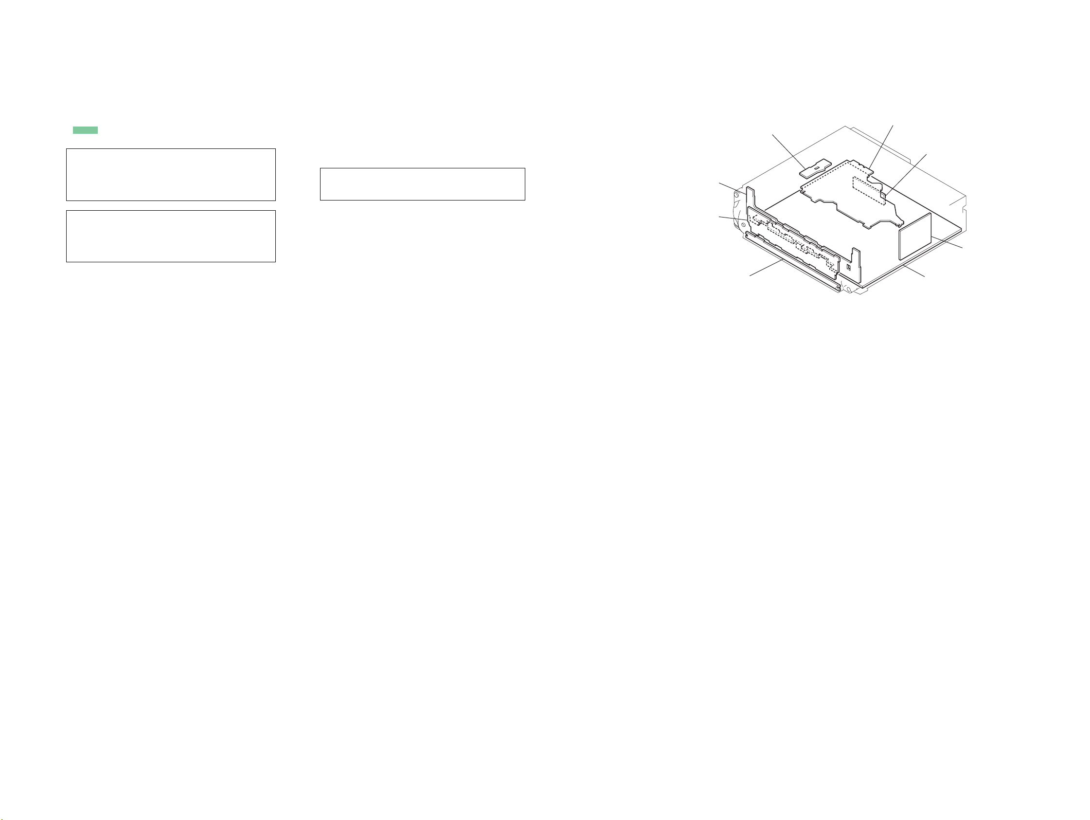
• Note for Printed Wiring Boards and Schematic Diagrams • Circuit Boards Location
)
MEX-R1
Note on Printed Wiring Board:
• X : parts extracted from the component side.
• Y : parts extracted from the conductor side.
f
•
• : Pattern from the side which enables seeing.
(The other layers' patterns are not indicated.)
Caution:
Pattern face side: Parts on the pattern face side seen from
(Conductor Side) the pattern face are indicated.
Parts face side: Parts on the parts face side seen from
(Component Side) the parts face are indicated.
Caution:
Pattern face side: Parts on the pattern face side seen from
(Side B) the pattern face are indicated.
Parts face side: Parts on the parts face side seen from
(Side A) the parts face are indicated.
: internal component.
Note on Schematic Diagram:
• All capacitors are in µF unless otherwise noted. (p: pF)
50 WV or less are not indicated except for electrolytics
and tantalums.
• All resistors are in Ω and 1/
specified.
• f : internal component.
• C : panel designation.
Note: The components identified by mark 0 or dotted line
with mark 0 are critical for safety.
Replace only with part number specified.
• A : B+ Line.
• H : adjustment for repair.
• Power voltage is dc 14.4V and fed with regulated dc power
supply from ACC and BATT cords.
• Voltages and waveforms are dc with respect to ground
under no-signal (detuned) conditions.
no mark : DVD PLAY
[]: CD PLAY
(): TUNER
∗ : Impossible to measure
• Voltages are taken with a V OM (Input impedance 10 MΩ).
Voltage variations may be noted due to normal production tolerances.
• Waveforms are taken with a oscilloscope.
Voltage variations may be noted due to normal production tolerances.
• Circled numbers refer to waveforms.
• Signal path.
L : DVD/CD (VIDEO)
F : DVD/CD (AUDIO)
J : OPTICAL OUTPUT
f : TUNER
E : AUX IN
4
W or less unless otherwise
BASE board
DISPLAY board
PRESET board
SERVO board
SENSOR board
SPEAKER board
tuner unit
(TUX201
MAIN board
MEX-R1
2121

MEX-R1
5-4. PRINTED WIRING BOARD – SERVO Section (1/2) –
1 2 3 4 5 6 7 8 9 10 11
SERVO BOARD (SIDE A)
A
B
C
R126
R120
C144
R138
R45
R37
C97
R38
C143
R123
R42
C102
R116
C101
C83
C84
C100
C146
RB14
R36
C91
X1
C90
C96
R97
C87
C104
C73
R98
C89
R46
C95
FB14
R35
RB12
C114
C121
C69
C70
R99
55
C86
C103
C72
108
109
R96
54
C71
C81
C65
C76
C80
C110
C115
D
R111
R170
C156
FB12
R172
FB11
R173
E
C153
C125
C128
C154
C123
F
IC8
C133
1
2
IC5
G
(CHUCKING END)
• See page 21 for Circuit Boards Location.
L8
C85
R110
3
C124
1
C126
3
R81
C54
R95
R109
FB10
C33
D5
SW3
(DOWN)
C56
IC6
C117
R108
FB9
R175
D3
C122
R63
R91
R90
C112
C129
BP1
C62
R86
C116
C111
C127
BP8
C52
RB7
R171
R169
R77
162
RB6
D4
R168
R4
R76
R72
1
RB5
C48
R66
C82
216
R74
R131
RB1
C77
C94
163
C131
C92
R127
C105
R154
RB4
C130
3
IC9
1
E5
R129
R130
R132
C106
R153
C155
RB3
E4
R71
FB8
E3
R73
: Uses unleaded solder.
E2
E1
R8
R6
11
1-866-215-
(11)
• Semiconductor
Location
Ref. No. Location
D3 F-3
D4 D-4
D5 G-3
MEX-R1
IC5 G-3
IC6 C-3
IC8 F-3
IC9 D-4
2222
 Loading...