

Sony MEXDV-150-UE, MEXDV-1500-U, MEXDV-1505-U Service manual
MEX-DV150UE/DV1500U/
μ
DV1505U
SERVICE MANUAL
Ver. 1.0 2008.12
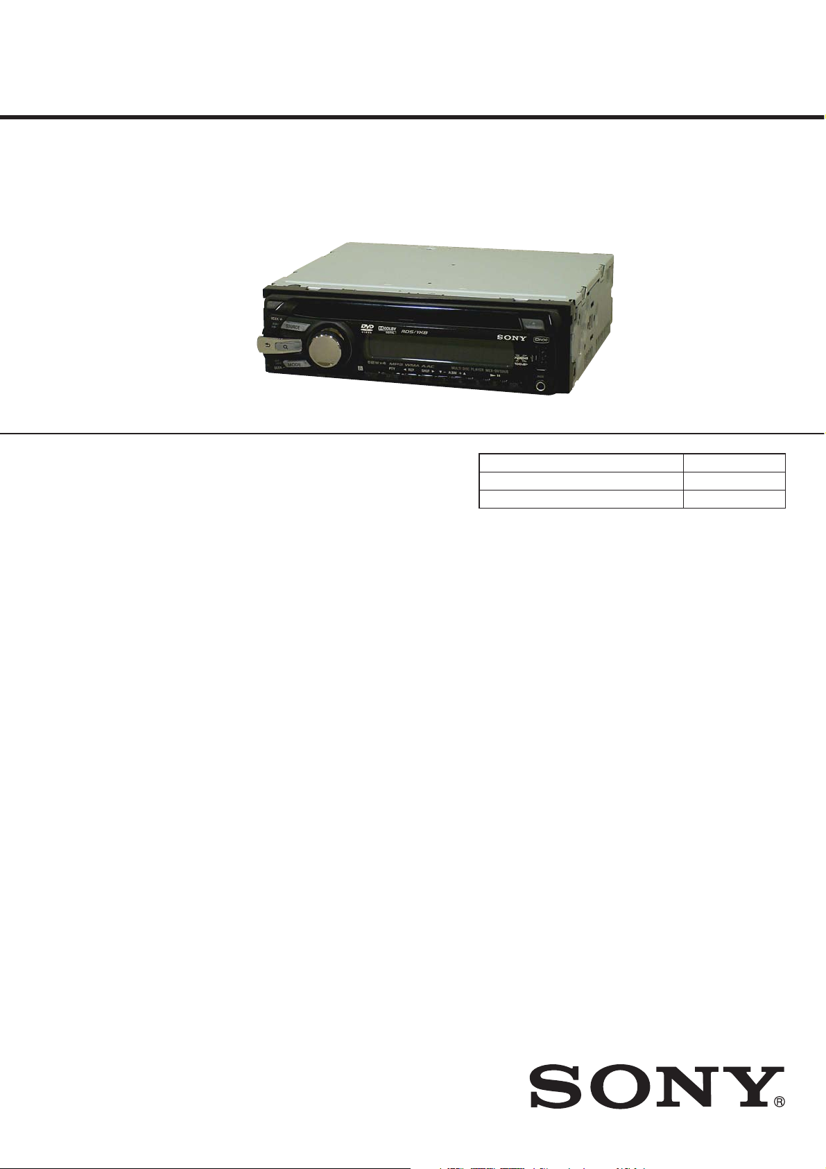
Photo: MEX-DV150UE
SPECIFICATIONS
System
Laser: Semiconductor laser
Signal format system: PAL/NTSC switchable
DVD/CD Player section
Signal-to-noise ratio: 120 dB
Frequency response: 10 – 20,000 Hz
Wow and flutter: Below measurable limit
Harmonic distortion: 0.01 %
Tuner section
FM
Tuning range:
AEP and UK models: 87.5 – 108.0 MHz
Russian model:
FM1/FM2: 87.5 – 108.0 MHz (at 50 kHz step)
FM3: 65 – 74 MHz (at 30 kHz step)
Asian model:
87.5 – 108.0 MHz (at 50 kHz step)
Latin American model:
87.5 – 107.9 MHz (at 200 kHz step)
Antenna (aerial) terminal:
External antenna (aerial) connector
Intermediate frequency: 10.7 MHz/450 kHz
Usable sensitivity: 9dBf
Selectivity: 75 dB at 400 kHz
Signal-to-noise ratio: 67 dB (stereo), 69 dB (mono)
Harmonic distortion at 1 kHz: 0.5 % (stereo),
0.3 % (mono)
Separation: 35 dB at 1 kHz
Frequency response: 30 – 15,000 Hz
AM (E and Indian models)
Tuning range:
Asian model:
531 – 1,602 kHz (at 9 kHz step)
Latin American model:
530 – 1,710 kHz (at 10 kHz step)
Antenna (aerial) terminal:
External antenna (aerial) connector
Intermediate frequency: 10.7 MHz/450 kHz
Sensitivity: 30
V
MW/LW (AEP, Russian and UK models)
Tuning range:
MW: 531 – 1,602 kHz
LW: 153 – 279 kHz
Antenna (aerial) terminal:
External antenna (aerial) connector
Intermediate frequency: 10.7 MHz/450 kHz
Sensitivity: MW:30μV,LW:40μV
USB Player section
Interface: USB (Full-speed)
Maximum current: 500mA
Power amplifier section
Outputs: Speaker outputs (sure seal connectors)
Speaker impedance: 4–8ohms
Maximum power output: 52 W I 4 (at 4 ohms)
General
Outputs:
Video output terminal
Rear audio output terminals
Power antenna (aerial) relay control terminal
Power amplifier control terminal
Inputs:
AUX audio input terminals
Antenna (aerial) input terminal
Parking break control terminal
AUX input jack (stereo mini jack)
USB signal input terminal
Tone controls:
Low: ±10 dB at 60 Hz
Mid: ±10 dB at 1 kHz
Hi: ±10dBat10kHz
AEP Model
UK Model
E Model
MEX-DV1500U
Russian Model
MEX-DV150UE
Indian Model
MEX-DV1505U
Model Name Using Similar Mechanism NEW
Mechanism Type MG-612U-187
Optical Pick-up Name KHS-360A
Power requirements: 12 V DC car battery
(negative ground (earth))
Dimensions: Approx. 178 I 50 I 179 mm
1
(7
/8 I 2 I 71/8 in) (w/h/d)
Mounting dimensions: Approx. 182 I 53 I 163 mm
1
/4 I 21/8 I 61/2 in) (w/h/d)
(7
Mass: Approx. 1.4 kg (3 lb 2 oz)
Supplied accessories:
Card remote commander: RM-X168
Parts for installation and connections (1 set)
Your dealer may not handle some of the above
listed accessories. Please ask the dealer for
detailed information.
US and foreign patents licensed from Dolby
Laboratories.
MPEG Layer-3 audio coding technology and
patents licensed from Fraunhofer IIS and
Thomson.
DivX, DivX Certified, and associated logos are
trademarks of DivX, Inc. and are used under
license.
This product is protected by certain intellectual
property rights of Microsoft Corporation. Use or
distribution of such technology outside of this
product is prohibited without a license from
Microsoft or an authorized Microsoft subsidiary.
Design and specifications are subject to change
without notice.
MUL TI DISC PLA YER
9-889-361-01
2008L05-1
©
2008.12
Sony Corporation
Audio&Video Business Group
Published by Sony Techno Create Corporation
MEX-DV150UE/DV1500U/DV1505U
Manufactured under license from Dolby Laboratories.
“Dolby” and the double-D symbol are trademarks of
Dolby Laboratories.
Windows Media, and the Windows logo are
trademarks or registered trademarks of Microsoft
Corporation in the United States and/or other
countries.
“DVD VIDEO,” “DVD-R,” “DVD-RW,” “DVD+R,” and “DVD+RW”
are trademarks.
“DivX” and “DivX Certified” are registered trademarks
or trademarks of DivX, Inc.
THIS PRODUCT IS LICENSED UNDER THE MPEG-4 VISUAL
PATENT PORTFOLIO LICENSE FOR THE PERSONAL AND
NON-COMMERCIAL USE OF A CONSUMER FOR DECODING
MPEG-4 VIDEO THAT WAS ENCODED BY A CONSUMER
ENGAGED IN A PERSONAL AND NON-COMMERCIAL
ACTIVITY AND/OR WAS OBTAINED FROM A VIDEO
PROVIDER LICENSED BY MPEG LA TO PROVIDE MPEG-4
VIDEO. NO LICENSE IS GRANTED OR SHALL BE IMPLIED
FOR ANY OTHER USE.
ADDITIONAL INFORMATION INCLUDING THAT RELATING
TO PROMOTIONAL, INTERNAL AND COMMERCIAL USES
AND LICENSING MAY BE OBTAINED FROM MPEG LA, LLC.
SEE
HTTP://WWW.MPEGLA.COM
NOTES ON CHIP COMPONENT REPLACEMENT
• Never reuse a disconnected chip component.
• Notice that the minus side of a tantalum capacitor may be damaged by heat.
FLEXIBLE CIRCUIT BOARD REPAIRING
• Keep the temperature of soldering iron around 270 °C during
repairing.
• Do not touch the soldering iron on the same conductor of the
circuit board (within 3 times).
• Be careful not to apply force on the conductor when soldering
or unsoldering.
CAUTION
Use of controls or adjustments or performance of procedures
other than those specifi ed herein may result in hazardous radiation exposure.
TABLE OF CONTENTS
1. SERVICING NOTES ............................................. 3
2. GENERAL .................................................................. 6
3. DISASSEMBLY
3-1. Disassembly Flow ........................................................... 12
3-2. Sub Panel Complete Assy ............................................... 12
3-3. DVD Mechanism Deck Block ........................................ 13
3-4. DC Fan (25X25) (M850), MAIN Board ......................... 13
3-5. Chassis (T612Z) Sub Assy, SENSOR Board .................. 14
3-6. Chassis (OP, ZA) Complete Assy ................................... 14
3-7. SERVO Board ................................................................. 15
4. ELECTRICAL CHECK ......................................... 16
5. DIAGRAMS
5-1. Block Diagram - SERVO/VIDEO/USB Section - .......... 17
5-2. Block Diagram - TUNER/AUDIO Section - .................. 18
5-3. Block Diagram
- PANEL/POWER SUPPLY Section - ............................ 19
5-4. Schematic Diagram - SERVO Section (1/3) - ................. 21
5-5. Schematic Diagram - SERVO Section (2/3) - ................. 22
5-6. Schematic Diagram - SERVO Section (3/3) - ................. 23
5-7. Printed Wiring Boards - SERVO Section - ..................... 24
5-8. Schematic Diagram - MAIN Board (1/3) - ..................... 25
5-9. Schematic Diagram - MAIN Board (2/3) - ..................... 26
5-10. Schematic Diagram - MAIN Board (3/3) - ..................... 27
5-11. Printed Wiring Board
- MAIN Board (Component Side) - ................................ 28
5-12. Printed Wiring Board
- MAIN Board (Conductor Side) - .................................. 29
5-13. Printed Wiring Boards - KEY Section - .......................... 30
5-14. Schematic Diagram - KEY Section - .............................. 31
6. EXPLODED VIEWS
6-1. Main Section ................................................................... 45
6-2. Front Panel Section ......................................................... 46
6-3. DVD Mechanism Deck Section (MG-612U-187) .......... 47
7. ELECTRICAL PARTS LIST .............................. 48
This label is located on the bottom of the
chassis.
CAUTION
RADIATION WHEN OPEN AND INTERLOCKS DEFEATED.
DO NOT VIEW DIRECTLY WITH OPTICAL INSTRUMENTS.
This label is located on the drive unit’s internal
chassis.
COMPONENTS IDENTIFIED BY MARK 0 OR DOTTED LINE
WITH MARK 0 ON THE SCHEMATIC DIAGRAMS AND IN
THE PARTS LIST ARE CRITICAL TO SAFE OPERATION.
REPLACE THESE COMPONENTS WITH SONY PARTS
WHOSE PART NUMBERS APPEAR AS SHOWN IN THIS
MANUAL OR IN SUPPLEMENTS PUBLISHED BY SONY.
:
CLASS 1M VISIBLE/INVISIBLE LASER
SAFETY-RELATED COMPONET WARNING!
2
Accessories are given in the last of the electrical parts list.
MEX-DV150UE/DV1500U/DV1505U
SECTION 1
SERVICING NOTES
NOTES ON HANDLING THE OPTICAL PICK-UP
BLOCK OR BASE UNIT
The laser diode in the optical pick-up block may suffer electrostatic break-down because of the potential difference generated by the
charged electrostatic load, etc. on clothing and the human body.
During repair, pay attention to electrostatic break-down and also
use the procedure in the printed matter which is included in the
repair parts.
fl
exible board is easily damaged and should be handled with
The
care.
NOTE ON LASER DIODE EMISSION CHECK
The laser beam on this model is concentrated so as to be focused
fl
on the disc re
ective surface by the objective lens in tha optical
pick-up block. Therefore, when checking the laser diode emission,
observe from more than 30 cm away from the objective lens.
UNLEADED SOLDER
Boards requiring use of unleaded solder are printed with the leadfree mark (LF) indicating the solder contains no lead.
(
Caution:
Some printed circuit boards may not come printed with
the lead free mark due to their particular size)
: LEAD FREE MARK
Unleaded solder has the following characteristics.
• Unleaded solder melts at a temperature about 40 °C higher
than ordinary solder.
Ordinary soldering irons can be used but the iron tip has to be
applied to the solder joint for a slightly longer time.
Soldering irons using a temperature regulator should be set to
about 350 °C.
Caution:
The printed pattern (copper foil) may peel away if
the heated tip is applied for too long, so be careful!
• Strong viscosity
Unleaded solder is more viscous (sticky, less prone to
fl
ow)
than ordinary solder so use caution not to let solder bridges
occur such as on IC pins, etc.
• Usable with ordinary solder
It is best to use only unleaded solder but unleaded solder may
also be added to ordinary solder.
NOTE THE IC4 ON THE SERVO BOARD
REPLACING
IC4 on the SERVO board cannot exchange with single. When this
part is damaged, exchange the entire mounted board.
NOTE FOR REPLACING THE COMPLETE MAIN
BOARD
If the complete MAIN board was replaced, be sure to refer to T echnical News published separately.
NOTE FOR THE 20-PIN CONNECTOR (CN901)
Do not use alcohol to clean the 20-pin connector (CN901) connecting the front panel with the main body.
Do not touch the connector directly with your bare hand. Poor contact may be caused.
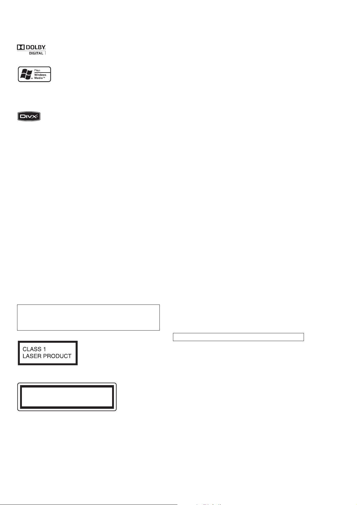
MODEL IDENTIFICATION
– Bottom View –
Region Code
Part No.
Label indication
Signal format
system
PAL 2
PAL 5
PAL 3
NTSC 4
PAL 5
Region
code
Part No.
4-120-894-0[]
4-120-895-0[]
4-120-896-0[]
4-120-897-0[]
4-120-898-0[]
Destination
DV1500U: AEP and UK models
DV150UE: Russian model
DV1500U: E (PAL) model
DV1500U: E (NTSC) model
DV1505U: Indian model
3
MEX-DV150UE/DV1500U/DV1505U
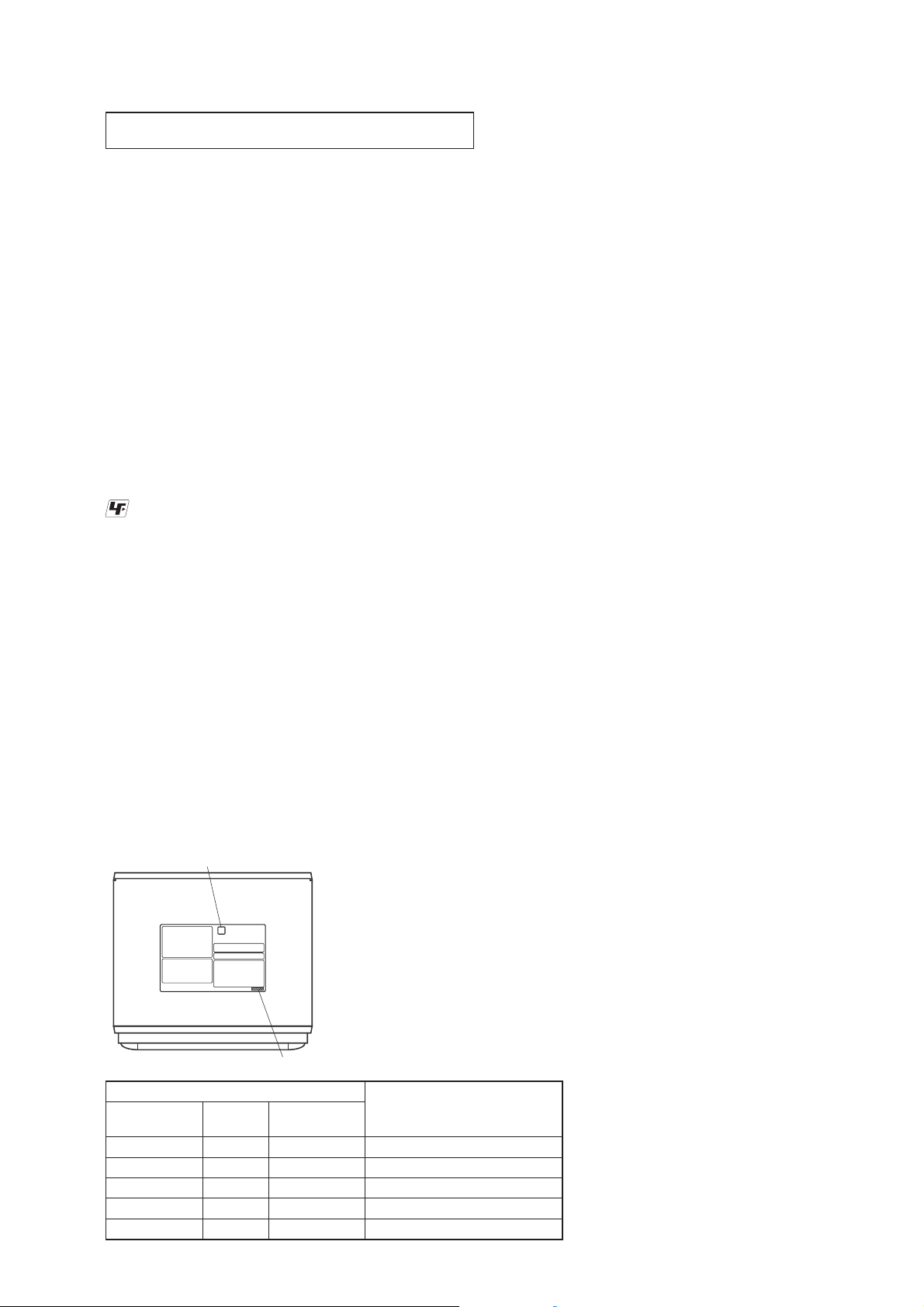
EXTENSION CABLE AND SERVICE POSITION
When repairing or servicing this set, connect the jig (extension cable) as shown below.
• Connect the MAIN board (CN101) and the SERVO board (CN3) with the extension cable (Part No. J-2502-062-1).
NOTE FOR FLEXIBLE BOARD OF THE OPTICAL
PICK-UP
When connecting or disconnecting the fl exible board of the optical pick-up to or from the CN2 of the SERVO board, follow the
procedure given below.
Note:
When soldering the short lands, solder within 5 seconds at the tem-
perature of soldering iron below 300°C.
Disconnection:
1. Solder two shortland.
fl
2. Disconnect the
board.
Connection:
1. Connect the fl exible board to the CN2 of the SERVO board.
2. Unsolder two shortland.
exible board from the CN2 of the SERVO
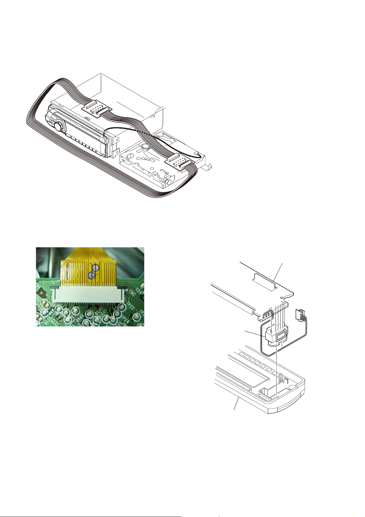
NOTE FOR REPLACING OF THE USB CONNECTOR
(CN902)
To replace the USB connector requires alignment.
1. Insert the USB connector into the front panel.
2. Place the KEY board on the front panel and align the terminals
of the USB connector with the holes in the KEY board.
3. Solder the six terminals of the connector.
KEY board
USB (socket) connector
front panel
4
MEX-DV150UE/DV1500U/DV1505U
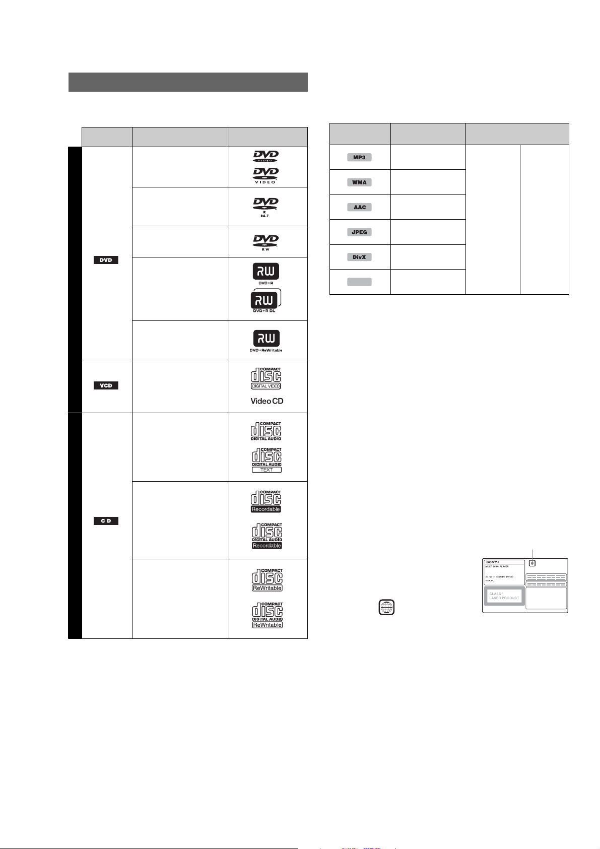
Playable discs and symbols used in this manual
This unit can play various video/audio discs.
The following chart helps you to check if a disc is supported by this unit,
as well as what functions are available for a given disc type.
Disc symbol
in manual
VIDEO
AUDIO
*1 Audio files can also be stored. For details.
*2 Video/image files can also be stored. For details.
Note
“DVD” may be used in this manual as a general term for DVD VIDEOs, DVD-Rs/
DVD-RWs, and DVD+Rs/DVD+RWs.
Disc format Disc logo
DVD VIDE O
1
DVD- R*
DVD- R DL*
1
(Video mode/VR mode)
DVD- RW*
1
(Video mode/VR mode)
DVD+R*
DVD+ R DL*
DVD+ RW*
1
1
1
Video CD
(Ver. 1.0/1.1/2.0)
Audio CD
CD-ROM*
CD-R*
CD-RW*
2
2
2
The following chart shows the supported compression formats, their file
types, and the disc types on which those files can be stored.
Available functions differ depending on the format, regardless of disc
type. The format symbols below appear next to the description of
functions available for that format.
Format symbol
in manual
File type Storable disc type
MP3 audio file
WMA audio file
AAC audio file
JPEG image file
DATA DVDs
DVD -RO M
DVD -R
DVD -R DL
DVD -RW
DVD+R
DATA CDs
CD-ROM
CD-R
CD-RW
DVD +R DL
®
DivX
video file
MPEG-4
Tip
For details on compression formats.
MPEG-4 video file
DVD +RW
Unsupported discs
The following discs cannot be played on this unit.
•8cm(3
•12cm (4
• CD-ROM containing files other than MP3/WMA/AAC/JPEG/DivX/
•SA-CD
•CD-G
•Photo-CD
• VSD (Video Single Disc)
• DVD-ROM containing files other than MP3/WMA/AAC/JPEG/DivX/
•DVD-RAM
•DVD-Audio
• Active-Audio (Data)
• SVCD (Super Video CD)
•CDV
• Discs created in Packet Write format
• Discs in DTS format
Note
Even compatible discs may not be playable on this unit, depending on their
recorded condition.
Region code
The region system is used to protect
software copyrights.
The region code is located on the bottom
of the unit, and only DVDs labeled with
an identical region code can be played on
this unit.
DVDs labeled can also be played.
If you try to play any other DVD, the
message “Playback prohibited by region
code.” will appear on the monitor screen.
Depending on the DVD, no region code
maybe labeledeventhoughplayingthe
DVD is prohibited by area restrictions.
1
/4 in) discs
3
/4 in) discs utilizing only the inner 8 cm (31/4 in) data portion
(the rest is transparent)
MPEG-4
MPEG-4
ALL
Region code
5
MEX-DV150UE/DV1500U/DV1505U
R
R
R
RBR
R
R
R
RGR
(DV1500U: E model/DV1505U)
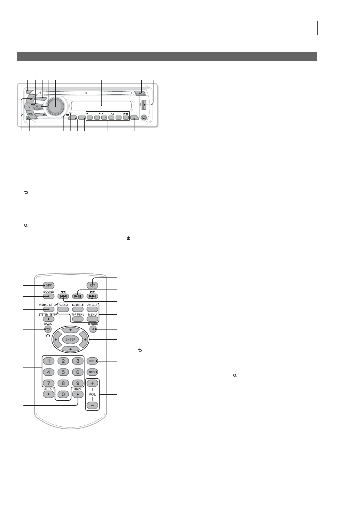
Location and function of controls
Main unit
OFF
SEEK
SOURCE
MODE
K
SEE
PUSH SOUND/ ENTER
Refer to the pages listed for details.
Instructions in this manual generally describe the controls
on the card remote commander. You can also use the
controls on the main unit if they have the same or similar
names to those on the card remote commander.
" OFF button
To power off/stop the source (press); shut off
completely (press and hold).
# (Back) button
To return to the previous display.
$ SOURCE button
To power on; change the source (Radio/Disc/USB/
AUX ).
% (Browse) button
To enter the Quick-BrowZer mode.*
& Control dial/SOUND/ENTER button
Toadjust thevolume/adjusta setting (rotate); open the
sound menu/apply a setting (press).
T
SETUP
E
ALBM ARTIST TRACK SHUF ZAP
REP SHUF
1 2 3 4 5 6
H
I
1
LOUDDISCREGTPTAAF
+
DM
ALBM
K
' Disc slot
To insert the disc.
( Display window
) ;(eject) button
To eject the disc.
* USB terminal
To connect to the USB device.
+ SEEK +/– buttons
Disc/USB:
To skip a chapter/track/scene/file (press); reverse/fastforward disc (pre ss and hold momentarily); reverse/
fast-forward track (press and hold).*
Radio:
To tune in stations automatically (press); find a station
manually (press and hold).
, (front panel release) button
SECTION 2
GENERAL
AUX
DSPLSCRL
L
M
This section is extracted
from instruction manual.
- MODE button
To select the radio band (FM/AM); select an auxiliary
device connected to the AUX input jack (front) or
AUX IN jack (rear).
. Receptor for the card remote commander
/ RESET button
0 SETUP button
To open the system setup menu.
1 SCRL (Scroll) button
To scroll the display item.
2 Number buttons
Disc/USB:
: C REP
: SHUF #
/: ALBM –/+ (7/W)
To skip an album or folder/move the cursor
(press); skip albums or folders continuously
(press and hold).
: V (play/pause)
To start/pause playback.
Radio:
To receive stored stations (press); store stations
(press and hold).
3 DSPL (Display) button
2
To change the display item.
4 AUX input jack
To connect a portable audio device.
*1 When a CD/MP3/WMA/AAC/JPEG/DivX/MPEG-4 is played.
*2 Operation differs depending on the disc.
About USB cap
When not using the USBterminal *, use the supplied USB cap to
prevent dust or dirt entering . Keep the USB cap out of the reach
of children to prevent accidental swallowing.
Card remote commander RM-X168
Refer to the pages listed for details.
Remove the insulation film before use.
" OFF button
RB
RT
RE
RG
RH
RI
RK
To power off/stop the source (press); shut off
completely (press and hold).
# SOUND button
To open the sound menu.
$ VISUAL SETUP button
To open the play mode/visual setup menu.
% SYSTEM SETUP button
To open the system setup menu.
& (Back)/0 button
To return to the previous display; return to the menu
on a VCD*
' Number buttons
Disc:
To locate a title/chapter/track.
Radio:
To receive stored stations (press); store stations
(press and hold).
( CLEAR button
To delete an entered number.
) DSPL (Display) button
To change display items.
* ATT (Attenuate) button
To attenuate the sound (to cancel, press again).
+ V (Play/Pause) button
To start/pause playback.
1
.
, N/. buttons
Disc/USB:
To skip a chapter/track/scene/file (press); reverse/
fast-forward disc (press and hold momentarily);
reverse/fast-forward track (press and hold).*
Radio:
To tune in stations automatically (press); find a
station manually (press and hold).
- DVD playback setting buttons
"6%*0:
To change the audio language/format.
(For VCD/CD/MP3/WMA/AAC, to change the
audio channel.)
46#5*5-&:
To change the subtitle language.
"/(-&:
To change the viewing angle.
501.&/6:
To open the top menu on a DVD.
.&/6:
To open the menu on a disc.
. (Browse) button
To enter the Quick-BrowZer mode.*
/ /./N/ (Cursor)/ENTER buttons
To move the cursor and apply a setting.
0 SRC (Source) button
To power on; change the source (Radio/Disc/USB/
AUX).
1 MODE button
To select the radio band (FM/AM); select an
auxiliary device connected to the AUX input jack
(front) or AUX IN jack (rear).
2 VOL (Volume) +/– buttons
To adjust the volume.
*1 When playing with PBC function.
*2 Operation differs depending on the disc.
*3 When a CD/MP3/WMA/AAC/JPEG/DivX/MPEG-4 is played.
Note
If the unit is turned off an d the display disappears, it cannot be
operated with the card remote com mander unless
on the main unit is pressed, or a d isc is inserted to activate the
unit first.
2
3
4063$&
6
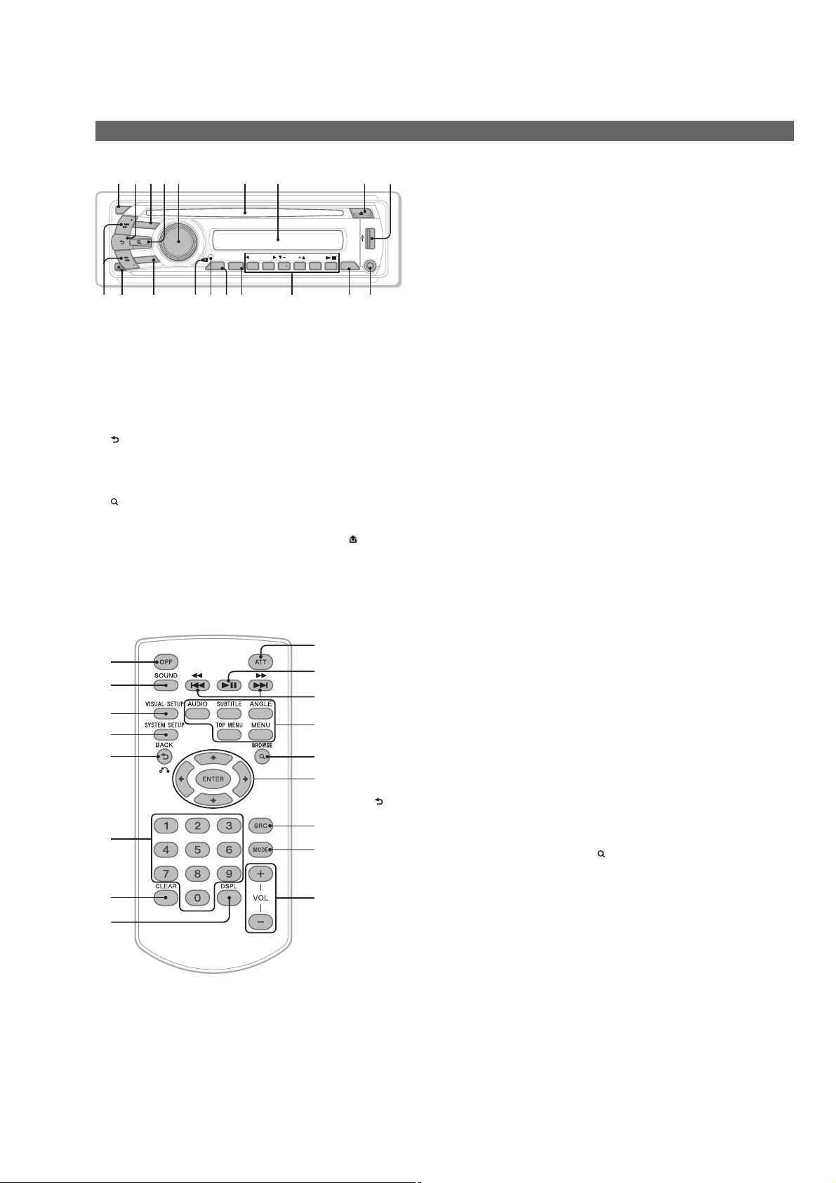
(DV150UE/DV1500U: AEP and UK models)
Location and function of controls
Main unit
OFF
SEEK
SOURCE
MODE
SEEK
PUSH SOUND/ ENTER
RTRB MRERRRK
Refer to the pages listed for details.
Instructions in this manual general ly describe the controls on
the card remote commander. You can also use the controls on
the main unit if they have the same or similar names to those
on the card remote comm ander.
" OFF button
To power off/stop the source (press); shut off completely
(press and hold).
# (Back) button
To return to the previous display.
$ SOURCE button
To power on; change the source (Radio/Disc/USB/AUX).
% (Browse) button
To enter the Quick-BrowZer mode.*
& Control dial/SOUND/ENTER button
To adjust the volume/adjust a setting (rotate); open the
sound menu/apply a setting (press).
SETUP
RGRH
ALBM ARTIST TRACK SHUF ZAP
REPPTY SHUF
ALBM
1 2 3 4 5 6
1
+
DM
LOUDDISCREGTPTAAF
AUX
DSPLAF/TA
RLRI
' Disc slot
To insert the disc.
( Display window
) ;(eject) button
To eject the disc.
* USB terminal
To connect to the USB device.
+ SEEK +/– buttons
Disc/USB:
To skip a chapter/track/scene/file (press); reverse/fastforward disc (press and hold momentarily); reverse/fastforward track (press and hold).*
Radio:
To tune in stations automatically (press); find a station
manually (press and hol d).
, (front panel release) button
2
MEX-DV150UE/DV1500U/DV1505U
- MODE button
To select the radio band (FM/MW/LW); select an
auxiliary device connec ted to the AUX input jack (front)
or AUX IN jack (rear).
. Receptor for the card remote commander
/ RESET button
0 SETUP button
To open the system setup menu.
1 AF (Alternative Frequencies)/TA (Traffic
Announcement)/PTY (Program Type) button
To set AF and TA (press); select PTY (press and hold) in
RDS.
2 Number buttons
Disc/USB:
: C REP
: SHUF #
/: ALBM –/+ (7/W)
To skip an album or folder/move the cursor (press);
skip albums or folder s continuously (press an d hold).
: V (play/pause)
To start/pause playback.
Radio:
To receive stored stations (pr ess); store
stations (press and hold).
3 DSPL (Display) button
To change the display item.
4 AUX input jack
To connect a portable audio device.
*1 When a CD/MP3/WMA/AAC/JPEG/DivX/MPEG-4 is played.
*2 Operation differs depending on the disc.
About USB cap
When notusing the USB terminal *, use the supplied USB cap to
prevent dust or dirt entering. Keep th e USB cap out of the reach of
children to prevent accidental swallowing.
Card remote commander RM-X168
RB
RT
RE
RG
RH
RI
RK
Refer to the pages listed for details.
Remove the insulation film before use.
" OFF button
To power off/stop the source (press); shut off completely
(press and hold).
# SOUND button
To open the sound menu.
$ VISUAL SETUP button
To open the play mode/visual setup menu.
% SYSTEM SETUP button
To open the system setup menu.
& (Back)/0 button
To return to the previous display; retu rn to the menu on a
1
VCD*
.
' Number buttons
Disc:
To locate a title/chapter/track.
Radio:
To receive stored stations (pr ess); store stations
(press and hold).
( CLEAR button
To delete an entered number.
) DSPL (Display) button
To change display items.
* ATT (Attenuate) button
To attenuate the sound (to cancel, press
again).
+ V (Play/Pause) button
To start/pause playback.
, N/. buttons
Disc/USB:
To skip a chapter/track/scene/ file (press); reverse/fastforward disc (press and hold momentarily); reverse/fastforward track (press and hold).*
Radio:
Totune instations automatically (press); find a station
manually (press and hold).
- DVD playback setting buttons
"6%*0:
To change the audio language/format.
(For VCD/CD/MP3/WMA/AAC, to change the audio
channel.)
46#5*5-&:
To change the subtitle language.
"/(-&:
To change the viewing angle.
501.&/6:
To open the top menu on a DVD.
.&/6:
To open the menu on a disc.
. (Browse) button
To enter the Quick-BrowZer mode.*
/ /./N/ (Cursor)/ENTER buttons
To move the cursor and apply a setting.
0 SRC (Source) button
To power on; change the source (Radio/Disc/USB/AUX).
1 MODE button
To select the radio band (FM/MW/LW); select an
auxiliary device connected to the AUX input jack (front)
or AUX IN jack (rear).
2 VOL (Volume) +/– buttons
To adjust the volume.
*1 When pl aying with PBC function.
*2 Operatio n differs depending on the disc.
*3 When a CD/MP3/WMA/AAC/JPEG/DivX/MPEG-4 is played.
Note
If the unit is turned off and t he display disappears, it cannot be
operated with the card remote commande r unless
main unit is pressed, or a disc is inser ted to activate the unit first.
2
3
4063$& on the
7
MEX-DV150UE/DV1500U/DV1505U
L
R
AUX
IN
VIDEO
OUT
FRONT
AUDIO OUT
REAR /SUB
AUDIO OUT
*
3
VIDEO OUT
AUX IN
VIDEO OUT
FRONT
AUDIO OUT
REAR /SUB
AUDIO OUT
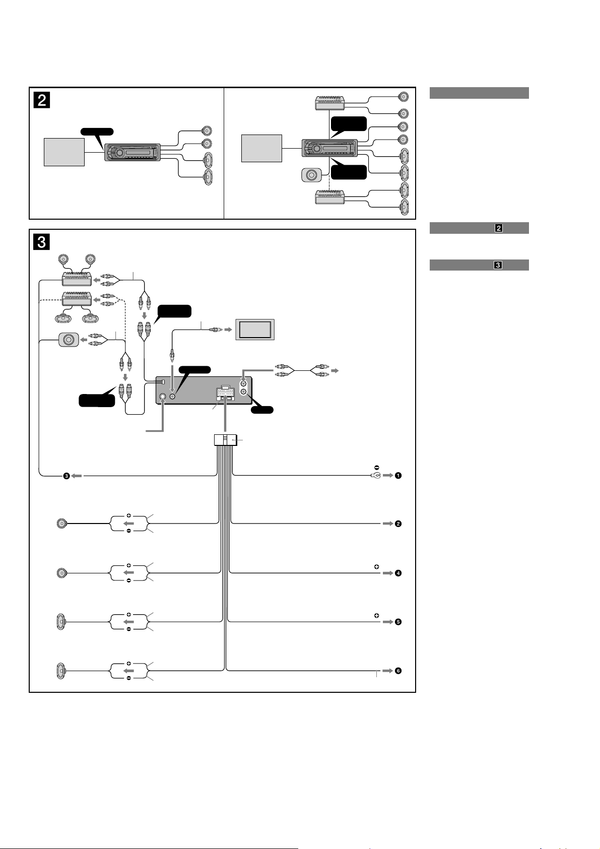
(DV1500U: E model/DV1505U)
AB
Monitor*
Monitor*
* not supplied
no suministrado
*1RCA pin cord (not supplied)
2
*
For details on connecting to the parking
brake switch cord, see “Connecting the
parking brake cord (ǰ)” on the reverse
side.
3
*
AUDIO OUT can be switched SUB or
REAR. For details, see the supplied
Operating Instructions.
4
*
Auxiliary device such as hideaway
navigation device,TV tuner box, etc.
Monitor (not supplied)
Monitor (no suministrado)
ʍ
Black
Negro
Blue
Azul
Red
Rojo
*1Cable con terminales RCA
(no suministrado)
2
*
Para obtener detalles acerca de cómo
conectar el cable de conmutación del
freno de estacionamiento, consulte
“Conexión del cable del freno de
estacionamiento (ǰ)” en el dorso.
3
*
AUDIO OUT (salida de audio) puede
cambiarse a SUB o REAR. Para obtener
información, consulte el manual de
instrucciones suministrado.
4
*
Dispositivo auxiliar como, por
ejemplo, un dispositivo de navegación
independiente, un sintonizador de
televisión, etc.
*
Max. supply current 0.1 A
Corriente máx. de alimentación de 0,1 A
* not supplied
no suministrado
Left
Izquierdo
Right
Derecho
Monitor*
Monitor*
from car antenna (aerial)
desde la antena del automóvil
AMP REM
Max. supply current 0.3 A
Corriente máx. de alimentación de 0,3 A
1
*
1
*
*
Fuse (10 A)
Fusible (10 A)
Blue/white striped
Con rayas azules y blanca
White
Blanco
White/black striped
Con rayas blancas y negras
Gray
Gris
Gray/black striped
Con rayas grises y negras
1
Cautions
• This unit is designed for negative ground (earth) 12 V
DC operation only.
• Do not get the leads under a screw, or caught in
moving parts (e.g. seat railing).
• Before making connections, turn the car ignition off to
avoid short circuits.
• Connect the yellow and red power supply leads only
after all other leads have been connected.
• Run all ground (ear th) leads to a common
ground (earth) point.
• Be sure to insulate any loose unconnected leads with
electrical tape for safety.
Notes on the power supply lead (yellow)
• When connecting this unit in combination with other
stereo components, the connected car circuit’s rating
must be higher than the sum of each component’s
fuse.
• When no car circuits are rated high enough, connect
the unit directly to the battery.
Note
Before installing, make sure that the catches on both sides of
the bracket ʌ are bent inwards 2 mm (
straight or bent outwards, the unit will not be installed securely
and may spring out.
3
/32 in). If the catches are
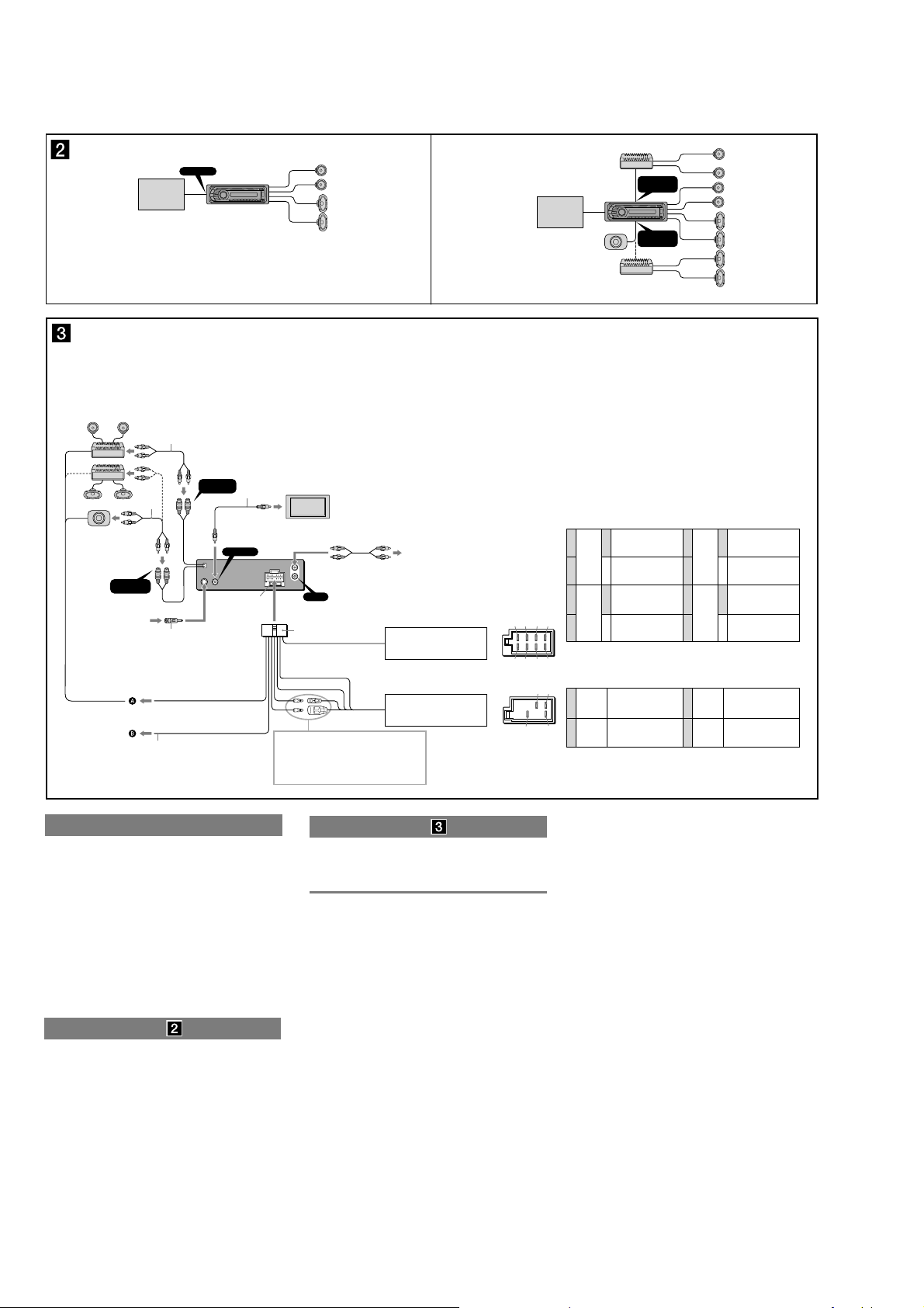
Connection example
Notes (Ǯ-B)
• Be sure to connect the ground (earth) lead before connecting
the amplifier.
• The alarm will only sound if the built-in amplifier is used.
Connection diagram
ɗ To a metal surface of the car
First connect the black ground (earth) lead, then connect
the yellow and red power supply leads.
ɘ To the power antenna (aerial) control lead
or power supply lead of antenna (aerial)
booster
Notes
• It is not necessary to connect this lead if there is no
power antenna (aerial) or antenna (aerial) booster, or with
a manually-operated telescopic antenna (aerial).
• When your car has a built-in FM/AM antenna (aerial) in
the rear/side glass, see “Notes on the control and power
supply leads.”
ə To AMP REMOTE IN of an optional power
amplifier
This connection is only for amplifiers. Connecting any other
system may damage the unit.
ɚ To the +12 V power terminal which is
energized in the accessory position of the
ignition switch
Notes
• If there is no accessory position, connect to the +12 V
4
ANT REM
power (battery) terminal which is energized at all times.
Be sure to connect the black ground (earth) lead to a
metal surface of the car first.
• When your car has a built-in FM/AM antenna (aerial) in
the rear/side glass, see “Notes on the control and power
supply leads.”
ɛ To the +12 V power terminal which is
energized at all times
Be sure to connect the black ground (earth) lead to a metal
surface of the car first.
ɜ To the parking brake switch cord
Notes on the control and power supply leads
• The power antenna (aerial) control lead (blue) supplies +12 V
DC when you turn on the tuner.
• When your car has built-in FM/AM antenna (aerial) in the
rear/side glass, connect the power antenna (aerial) control
lead (blue) or the accessory power supply lead (red) to the
power terminal of the existing antenna (aerial) booster.For
details, consult your dealer.
• A power antenna (aerial) without a relay box cannot be used
with this unit.
Memory hold connection
When the yellow power supply lead is connected, power will
always be supplied to the memory circuit even when the ignition
switch is turned off.
Notes on speaker connection
• Before connecting the speakers, turn the unit off.
• Use speakers with an impedance of 4 to 8 ohms, and with
adequate power handling capacities to avoid its damage.
• Do not connect the speaker terminals to the car chassis, or
connect the terminals of the right speakers with those of the
left speaker.
• Do not connect the ground (earth) lead of this unit to the
negative (–) terminal of the speaker.
• Do not attempt to connect the speakers in parallel.
• Connect only passive speakers. Connecting active speakers
(with built-in amplifiers) to the speaker terminals may damage
the unit.
• To avoid a malfunction, do not use the built-in speaker leads
installed in your car if the unit shares a common negative (–)
lead for the right and left speakers.
• Do not connect the unit’s speaker leads to each other.
Notes on connection
• If speaker and amplifier are not connected correctly,
“FAILURE” appears in the display. In this case, make sure the
speaker and amplifier are connected correctly.
• If you are to use the monitor for the rear seats, connect the
parking brake switch cord to the ground (earth).
8
Left
Izquierdo
Right
Derecho
Green
Verde
Green/black striped
Con rayas verdes y negras
Purple
Morado
Purple/black striped
Con rayas moradas y negras
Yellow
Amarillo
Light green
Verde claro
PARKING BRAKE
2
*
MEX-DV150UE/DV1500U/DV1505U
Foot brake type
Tipo de freno de pedal
Parking brake switch cord
Cable de conmutación del
freno de estacionamiento
12
ʎ
ʏ
j
Hand brake type
Tipo de freno manual
Face the hook inwards.
El gancho debe encontrarse
en la parte interior.
Parking brake switch cord
Cable de conmutación del
freno de estacionamiento
jj
ʌ
12 3
Dashboard
Tablero
ʌ
ʌ
max. size
5 × 8 mm
7
/32 ×11/32 in)
(
Tamaño máx.
5 × 8 mm
182 mm
A
TOYOTA
ʒ
Bracket
Soporte
Existing parts supplied with your car
Piezas existentes suministradas con su automóvil
53 mm
to dashboard/center console
al tablero o consola central
Bracket
Soporte
Claws
Uñas
ʒ
max. size
5 × 8 mm
7
/32 ×11/32 in)
(
Tamaño máx.
5 × 8 mm
B NISSAN
ʒ
max. size
5 × 8 mm
7
/32 ×11/32 in)
(
Tamaño máx.
5 × 8 mm
ʏ
Bracket
Soporte
Existing parts supplied with your car
Piezas existentes suministradas con su automóvil
Fire wall
Cortafuegos
ʐ
to dashboard/center console
al tablero o consola central
Bracket
Soporte
ʑ
ʒ
max. size
5 × 8 mm
7
/32 ×11/32 in)
(
Tamaño máx.
5 × 8 mm
Precautions
• Choose the installation location carefully so that the
unit will not interfere with normal driving operations.
• Avoid installing the unit in areas subject to dust, dirt,
excessive vibration, or high temperatures, such as in
direct sunlight or near heater ducts.
• Use only the supplied mounting hardware for a safe
and secure installation.
Mounting angle adjustment
Adjust the mounting angle to less than 45°.
Connecting the parking brake
cord
Be sure to connect the parking cord (Light green) of ʍ
to the parking brake switch cord. The mounting position
of the parking brake switch cord depends on your car.
Consult your car dealer or your nearest Sony dealer for
further details.
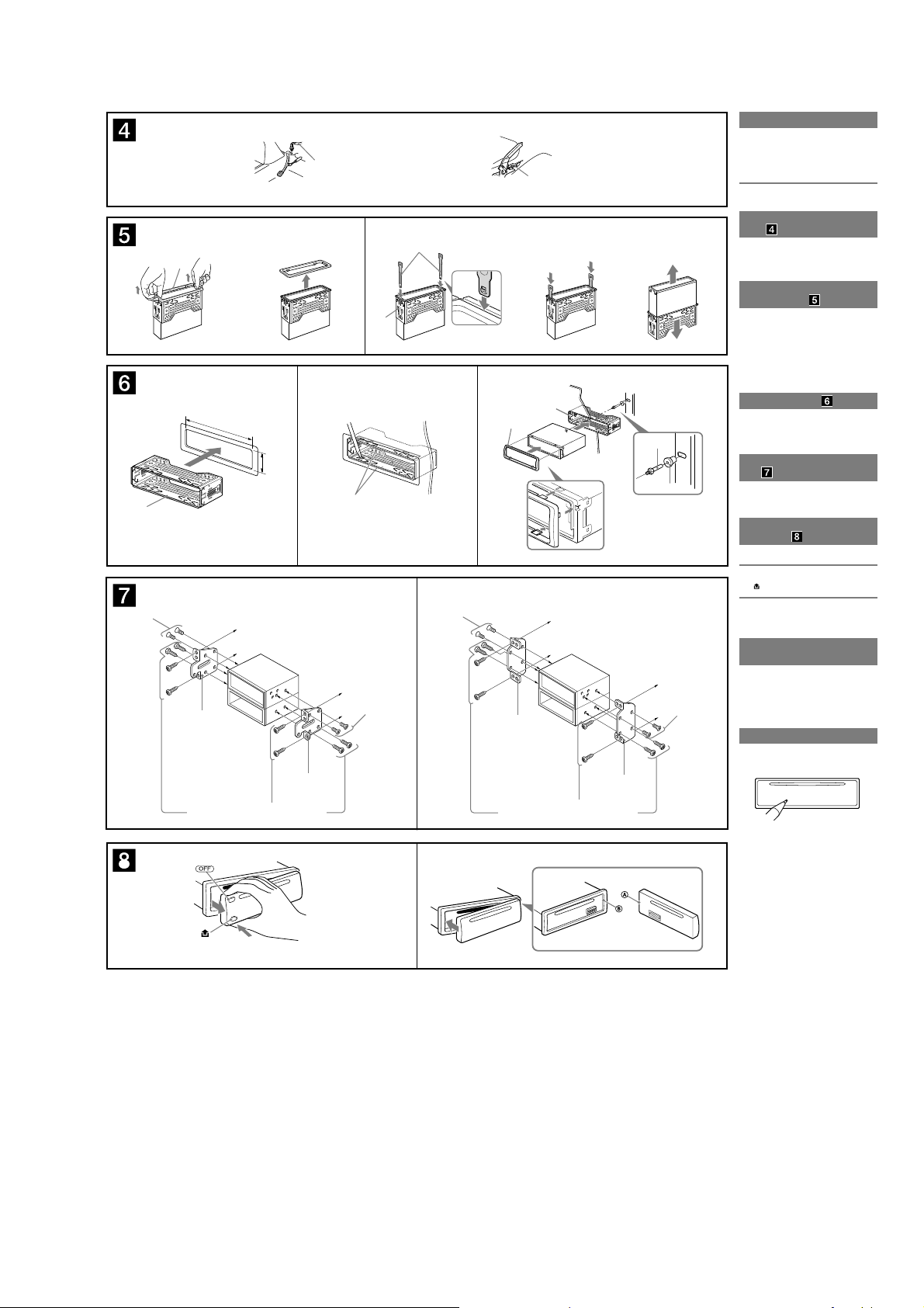
Removing the protection collar
and the bracket
Before installing the unit, remove the protection
collar ʏ and the bracket ʌ from the unit.
1 Remove the protection collar ʏ.
Pinch both edges of the protection collar ʏ, then
pull it out.
2 Remove the bracket ʌ.
ɗ Insert both release keys ʎ together between
the unit and the bracket
ɘ Pull down the bracket
to separate.
ʌ until they click.
ʌ, then pull up the unit
Mounting example
Installation in the dashboard
Notes
• Bend these claws outward for a tight fit, if necessary (Dz-2).
• Make sure that the 4 catches on the protection collar ʏ are
properly engaged in the slots of the unit (Dz-3).
Mounting the unit in a Japanese
car
You may not be able to install this unit in some makes of
Japanese cars. In such a case, consult your Sony dealer.
Note
To prevent malfunction, install only with the supplied screwsʒ.
How to detach and attach the
front panel
Before installing the unit, detach the front panel.
Ǵ-A To detach
Before detaching the front panel, be sure to press ŨƎƅƅũ.
, and pull it off towards you.
Press
Ǵ-B To attach
Engage part ʦ of the front panel with part ʧ of the unit,
as illustrated, and push the left side into position until it
clicks.
Warning if your car’s ignition
has no ACC position
Be sure to set the Auto Off function. For details, see the
supplied Operating Instructions.
The unit will shut off completely and automatically in
the set time after the unit is turned off, which prevents
battery drain.
If you do not set the Auto Off function, press and hold
ŨƎƅƅũ until the display disappears each time you turn
the ignition off.
RESET button
When the installation and connections are completed,
be sure to press the RESET button with a ball-point pen,
etc., after detaching the front panel.
A
B
9
MEX-DV150UE/DV1500U/DV1505U
(DV150UE/DV1500U: AEP and UK models)
A
* not supplied
nicht mitgeliefert
non fourni
non in dotazione
niet bijgeleverd
REAR/ SUB
AUDIO OUT
*
1
from car antenna (aerial)
*
von Autoantenne
de l’antenne de la voiture
dall’antenna dell’auto
van een auto-antenne
Max. supply current 0.3 A
max.Versorgungsstrom 0,3 A
Courant d’alimentation maximum 0,3 A
Alimentazione massima fornita 0,3 A
Max. voedingsstroom 0,3 A
Monitor*
Monitor*
Moniteur
Monitor*
Monitor*
2
*
4
AMP REM
PARKING BRAKE
3
*
*
*
ʍ
2
VIDEO OUT
FRONT
AUDIO OUT
VIDEO
OUT
Blue/white striped
Blauweiß gestreift
Rayé bleu/blanc
Rigato blu e bianco
Blauw/wit gestreept
Light green
Hellgrün
Vert clair
Verdechiaro
Lichtgroen
VIDEO OUT
Fuse (10 A)
Sicherung (10 A)
Fusible (10 A)
Fusibile (10 A)
Zekering (10 A)
2
*
1
*
Note for the antenna (aerial) connecting
If your car antenna (aerial) is an
ISO (International Organization for
Standardization) type, use the supplied
adaptor ʍ to connect it. First connect the
car antenna (aerial) to the supplied adaptor,
then connect it to the antenna (aerial) jack of
the master unit.
2
*
RCA pin cord (not supplied)
3
*
For details on connecting to the parking
brake switch cord, see“Connecting the
parking brake cord (ǰ)” on the reverse side.
4
*
AUDIO OUT can be switched SUB or REAR.
For details, see the supplied Operating
Instructions.
5
*
Auxiliary device such as hideaway
navigation device,TV tuner box, etc.
L
R
AUX
IN
AUX IN
1
*
Hinweis zum Anschließen der Antenne
Wenn Ihre Fahrzeugantenne der ISO-Norm
(Internationale Normungsgemeinschaft)
entspricht, schließen Sie sie mithilfe des
mitgelieferten Adapters ʍ an.Verbinden
Sie zuerst die Fahrzeugantenne mit dem
mitgelieferten Adapter und verbinden Sie
diesen dann mit der Antennenbuchse des
Hauptgeräts.
2
*
Cinchkabel (nicht mitgeliefert)
3
*
Informationen zum Anschließen der
Parkbremsenschaltleitung finden Sie unter
„Anschließen der Parkbremsenleitung (ǰ)“
auf der Rückseite.
4
*
AUDIO OUT kann zwischen SUB und REAR
umgeschaltet werden. Näheres hierzu finden
Sie in der Bedienungsanleitung.
5
*
Zusätzliches Gerät wie ein verstecktes
Navigationsgerät, ein Fernsehtuner usw.
Monitor (not supplied)
Monitor (nicht mitgeliefert)
Moniteur (non fourni)
Monitor (non in dotazione)
Monitor (niet bijgeleverd)
ʎ
See“Power connection diagram” on the reverse side for details.
Näheres dazu finden Sie im „Stromanschlussdiagramm“. Blättern
Sie dazu bitte um.
Voir le « Schéma de raccordement d’alimentation » au verso pour
plus de détails.
Per ulteriori informazioni, vedere“Diagramma dei collegamenti di
alimentazione”che si trova sul retro.
Zie "Voedingsaansluitschema" op de achterkantvoor meer details.
B
5
*
from the car’s speaker connector
vom Lautsprecheranschluss des Fahrzeugs
du connecteur de haut-parleur de la voiture
dal connettore del diffusore dell’auto
van de autoluidsprekeraansluiting
from the car’s power connector
vom Stromanschluss des Fahrzeugs
du connecteur d’alimentation de la voiture
dal connettore di alimentazione dell’auto
van de autovoedingsaansluiting
Monitor*
Monitor*
Moniteur
Monitor*
Monitor*
* not supplied
nicht mitgeliefert
non fourni
non in dotazione
niet bijgeleverd
1
*
Remarque sur le raccordement de l’antenne
Si votre antenne de voiture est de type
ISO (Organisation internationale de
normalisation), utilisez l’adaptateur fourni
ʍ pour la raccorder. Raccordez d’abord
l’antenne de voiture à l’adaptateur fourni et,
ensuite, à la prise d’antenne de l’appareil
principal.
2
*
Cordon à broche RCA (non fourni)
3
*
Pour plus de détails sur le raccordement du
cordon du capteur du frein à main, reportezvous à la section « Raccordement du cordon
du frein à main (ǰ) » au verso.
4
*
AUDIO OUT peut être commuté sur SUB
ou REAR.Pour obtenir plus de détails,
reportez-vous au mode d’emploi.
5
*
Appareil auxiliaire comme un appareil de
navigation dissimulé, un tunerTV, etc.
13 57
24 68
57
48
FRONT
AUDIO OUT
*
REAR/ SUB
AUDIO OUT
1
*
Nota per il collegamento dell’antenna
Se l’antenna dell’auto è di tipo
ISO (International Organization for
Standardization), utilizzare l’adattatore ʍ
in dotazione per collegarla. Collegare prima
l’antenna della macchina all’adattatore
in dotazione, quindi collegarla alla presa
dell’antenna dell’apparecchio principale.
2
*
Cavo a piedini RCA (non in dotazione)
3
*
Per ulteriori informazioni sulla modalità di
collegamento del cavo di commutazione
del freno a mano, consultare la sezione
“Collegamento del cavo del freno a mano
(ǰ)” sul lato opposto.
4
*
AUDIO OUT può essere impostato su
SUB o su REAR.Per ulteriori informazioni,
consultare il manuale di istruzioni per l’uso.
5
*
Dispositivo ausiliare quale un dispositivo di
navigazione hideaway, un sintonizzatoreTV
e così via.
Speaker, Rear, Right
Purple
Violett
Mauve
Paars
Grigio
Viola
Gray
Grau
Gris
Grijs
Yellow
Gelb
Jaune
Giallo
Geel
Blue
Blau
Bleu
Blauw
Blu
Lautsprecher hinten rechts
+
Haut-parleur, arrière, droit
Diffusore, posteriore, destro
Luidspreker, achter, rechts
Speaker, Rear, Right
Lautsprecher hinten rechts
Haut-parleur, arrière, droit
Diffusore, posteriore, destro
Luidspreker, achter, rechts
Speaker, Front, Right
Lautsprecher vorne rechts
+
Haut-parleur,avant, droit
Diffusore, anteriore, destro
Luidspreker,voor, rechts
Speaker, Front, Right
Lautsprecher vorne rechts
Haut-parleur,avant, droit
Diffusore, anteriore, destro
Luidspreker,voor, rechts
continuous power supply
permanente Stromversorgung
alimentation continue
alimentazione continua
continu voeding
power antenna (aerial) control
Motorantennensteuerung
antenne électrique
comando dell’antenna elettrica
automatische antenne
5
6–
7
8–
7
8
1
2–
3
4–
Negative polarity positions 2, 4, 6 and 8 have striped leads.
An den negativ gepolten Positionen 2, 4, 6 und 8 befinden sich gestreifte Adern.
Les positions de polarité négative 2, 4, 6 et 8 sont dotées de cordons rayés.
Le posizioni a polarità negativa 2, 4, 6 e 8 hanno cavirigati.
De posities voor negatieve polariteit (2, 4, 6 en 8) hebben gestreepte kabels.
4
5
Positions 1, 2, 3 and 6 do not have pins.
An Position 1, 2, 3 und 6 befinden sich keine Stifte.
Les positions 1, 2, 3 et 6 ne comportent pas de broches.
Le posizioni 1, 2, 3 e 6 non hanno piedini.
De posities 1, 2, 3 en 6 hebben geen pins.
1
*
Opmerking bij de antenne-aansluiting
Indien uw auto is uitgerust met een antenne
van het type ISO (International Organization
for Standardization), moet u die aansluiten
met behulp van de bijgeleverde adapter
ʍ. Sluit eerst de auto-antenne aan op
de bijgeleverde adapter en vervolgens de
antennestekker op het hoofdtoestel.
2
*
Tulpstekkersnoer (niet bijgeleverd)
3
*
Zie “Parkeerremkabel aansluiten (ǰ)” op
de achterkant voor meer informatie over
het aansluiten op het schakelsnoer van de
parkeerrem.
4
*
AUDIO OUT kan worden ingesteld op SUB
of REAR. Raadpleeg de gebruiksaanwijzing
voor meer informatie.
5
*
Randapparaat, zoals een verborgen
navigatieapparaat, televisietuner, enzovoort.
Speaker, Front, Left
Lautsprecher vorne links
+
Haut-parleur,avant, gauche
White
Diffusore, anteriore, sinistro
Weiß
Luidspreker,voor, links
Blanc
Speaker, Front, Left
Bianco
Lautsprecher vorne links
Wit
Haut-parleur,avant, gauche
Diffusore, anteriore, sinistro
Luidspreker,voor, links
Speaker, Rear, Left
Lautsprecher hinten links
+
Haut-parleur, arrière, gauche
Green
Diffusore, posteriore, sinistro
Grün
Luidspreker, achter, links
Vert
Speaker, Rear, Left
Verde
Lautsprecher hinten links
Groen
Haut-parleur, arrière, gauche
Diffusore, posteriore, sinistro
Luidspreker, achter, links
Red
switched power supply
Rot
geschaltete Stromversorgung
Rouge
alimentation commutée
Rosso
alimentazione commutata
Rood
geschakelde voeding
Black
Schwarz
ground (earth)
Noir
Nero
Zwart
Masse
masse
terra
aarding
Cautions
• This unit is designed for negative ground (earth) 12 V DC operation
only.
• Do not get the leads under a screw, or caught in moving parts (e.g.
seat railing).
• Before making connections, turn the car ignition off to avoid short
circuits.
• Connect the power supply lead ʎ to the unit and speakers before
connecting it to the auxiliary power connector.
• Run all ground (earth) leads to a common ground (earth)
point.
• Be sure to insulate any loose unconnected leads with electrical tape
for safety.
Notes on the power supply lead (yellow)
• When connecting this unit in combination with other stereo
components, the connected car circuit’s rating must be higher than
the sum of each component’s fuse.
• When no car circuits are rated high enough, connect the unit directly
to the battery.
Connection example
Notes (Ǯ-B)
• Be sure to connect the ground (earth) lead before connecting the amplifier.
• The alarm will only sound if the built-in amplifier is used.
Connection diagram
ɱ To AMP REMOTE IN of an optional power amplifier
This connection is only for amplifiers. Connecting any other system may
damage the unit.
ɲ To the parking brake switch cord
Warning
If you have a power antenna (aerial) without a relay box, connecting
this unit with the supplied power supply lead ʎ may damage the
antenna (aerial).
Notes on the control and power supply leads
• The power antenna (aerial) control lead (blue) supplies +12 V DC when you
turn on the tuner, or when you activate the AF (Alternative Frequency) orTA
(Traffic Announcement) function.
• When your car has built-in FM/MW/LW antenna (aerial) in the rear/side glass,
connect the power antenna (aerial) control lead (blue) or the accessory power
supply lead (red) to the power terminal of the existing antenna (aerial) booster.
For details, consult your dealer.
• A power antenna (aerial) without a relay box cannot be used with this unit.
Memory hold connection
When the yellow power supply lead is connected, power will always be supplied
to the memory circuit even when the ignition switch is turned off.
Notes on speaker connection
• Before connecting the speakers, turn the unit off.
• Use speakers with an impedance of 4 to 8 ohms, and with adequate power
handling capacities to avoid its damage.
• Do not connect the speaker terminals to the car chassis, or connect the
terminals of the right speakers with those of the left speaker.
• Do not connect the ground (earth) lead of this unit to the negative (–) terminal
of the speaker.
• Do not attempt to connect the speakers in parallel.
• Connect only passive speakers. Connecting active speakers (with built-in
amplifiers) to the speaker terminals may damage the unit.
• Toavoid a malfunction, do not use the built-in speaker leads installed in
your car if the unit shares a common negative (–) lead for the right and left
speakers.
• Do not connect the unit’s speaker leads to each other.
Notes on connection
• If speaker and amplifier are not connected correctly,“FAILURE” appears in
the display. In this case, make sure the speaker and amplifier are connected
correctly.
• If you are to use the monitor for the rear seats, connect the parking brake
switch cord to the ground (earth).
10
MEX-DV150UE/DV1500U/DV1505U
Foot brake type
Fußbremse
Type pédale de frein
Freno a pedale
Type voetrem
Parking brake switch cord
Parkbremsenschaltleitung
Cordon du capteur du frein
à main
Cavo di commutazione del
freno a mano
Schakelsnoer van de
parkeerrem
Hand brake type
Handbremse
Type frein à main
Freno a mano
Type handrem
Parking brake switch cord
Parkbremsenschaltleitung
Cordon du capteur du frein à main
Cavo di commutazione del freno
a mano
Schakelsnoer van de parkeerrem
ʐ
j
ʌ
12 3
182 mm
12
53 mm
ʌ
Claws
Klammern
Griffes
Morsetti
Klemhaken
ʏ
Face the hook inwards.
Der Haken muss nach innen
weisen.
Tournez le crochet vers
l’intérieur.
Con il gancetto rivolto verso
l’interno.
Het haakje moet naar binnen
wijzen.
jj
Dashboard
Armaturenbrett
Tableau de bord
Cruscotto
Dashboard
ʌ
ʐ
Fire wall
Motorraumtrennwand
Paroi ignifuge
Parete tagliafiamma
Brandschot
ʑ
ʒ
AB
Precautions
• Choose the installation location carefully so that the unit will not
interfere with normal driving operations.
• Avoid installing the unit in areas subject to dust, dirt, excessive
vibration, or high temperature, such as in direct sunlight or near
heater ducts.
• Use only the supplied mounting hardware for a safe and secure
installation.
Mounting angle adjustment
Adjust the mounting angle to less than 45°.
Connecting the parking brake cord
Be sure to connect the parking cord (Light green) of ʎ to the parking
brake switch cord. The mounting position of the parking brake switch
cord depends on your car. Consult your car dealer or your nearest Sony
dealer for further details.
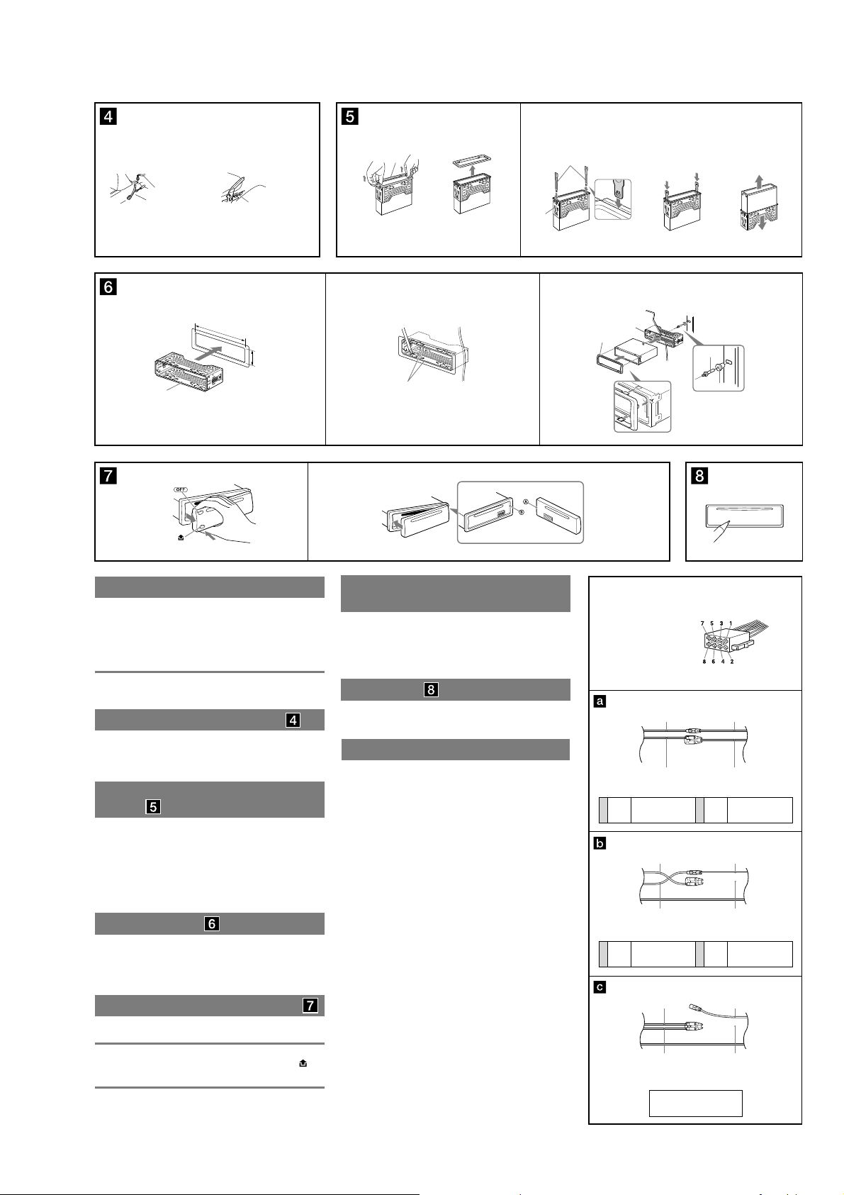
Removing the protection collar and the
bracket
Before installing the unit, remove the protection collar ʐ
and the bracket ʌ from the unit.
1 Remove the protection collar ʐ.
Pinch both edges of the protection collar ʐ, then pull it out.
2 Remove the bracket ʌ.
ɗ Insert both release keys ʏ together between the unit and
the bracket ʌ until they click.
ɘ Pull down the bracket ʌ, then pull up the unit to separate.
Mounting example
Installation in the dashboard
Notes
• Bend these claws outward for a tight fit, if necessary (Dz-2).
• Make sure that the 4 catches on the protection collar ʐ are properly engaged
in the slots of the unit (Dz-3).
How to detach and attach the front panel
Before installing the unit, detach the front panel.
dz-A To detach
Before detaching the front panel, be sure to press ŨƎƅƅũ. Press , and
pull it off towards you.
dz-B To attach
Engage part ʦ of the front panel with part ʧ of the unit, as illustrated,
and push the left side into position until it clicks.
Warning if your car’s ignition has no ACC
position
Be sure to set the Auto Off function. For details, see the supplied
Operating Instructions.
The unit will shut off completely and automatically in the set time after
the unit is turned off, which prevents battery drain.
If you do not set the Auto Off function, press and hold ŨƎƅƅũ until the
display disappears each time you turn the ignition off.
RESET button
When the installation and connections are completed, be sure to press
the RESET button with a ball-point pen, etc., after detaching the front
panel.
Power connection diagram
Auxiliary power connector may vary depending on the car. Check your
car’s auxiliary power connector diagram to make sure the connections
match correctly. There are three basic types (illustrated below).You
may need to switch the positions of the red and yellow leads in the car
stereo’s power supply lead.
After matching the connections and switched power supply leads
correctly, connect the unit to the car’s power supply. If you have any
questions and problems connecting your unit that are not covered in
this manual, please consult the car dealer.
Auxiliary power connector
Hilfsstromanschluss
Connecteur d’alimentation auxiliaire
Connettore di alimentazione ausiliaria
Hulpvoedingsaansluiting
Yellow
continuous power supply
Gelb
permanente Stromversorgung
4
Jaune
alimentation continue
Giallo
alimentazione continua
Geel
continu voeding
Yellow
switched power supply
Gelb
geschaltete Stromversorgung
4
Jaune
alimentation commutée
Giallo
alimentazione commutata
Geel
geschakelde voeding
Red
Rot
Rouge
Rosso
Rood
Yellow
Gelb
Jaune
Giallo
Geel
Red
Rot
Rouge
Rosso
Rood
Yellow
Gelb
Jaune
Giallo
Geel
Red
Rot
Rouge
Rosso
Rood
Yellow
Gelb
Jaune
Giallo
Geel
the car without ACC position
Fahrzeug ohne Zubehörposition (ACC oder I)
Véhicule sans position ACC
Auto priva della posizione ACC
7
7
Auto zonder ACC-positie
Rouge
Rosso
Rood
Rouge
Rosso
Rood
Red
Rot
Red
Rot
Red
Rot
Rouge
Rosso
Rood
Yellow
Gelb
Jaune
Giallo
Geel
switched power supply
geschaltete Stromversorgung
alimentation commutée
alimentazione commutata
geschakelde voeding
Red
Rot
Rouge
Rosso
Rood
Yellow
Gelb
Jaune
Giallo
Geel
continuous power supply
permanente Stromversorgung
alimentation continue
alimentazione continua
continu voeding
Red
Rot
Rouge
Rosso
Rood
Yellow
Gelb
Jaune
Giallo
Geel
11
MEX-DV150UE/DV1500U/DV1505U
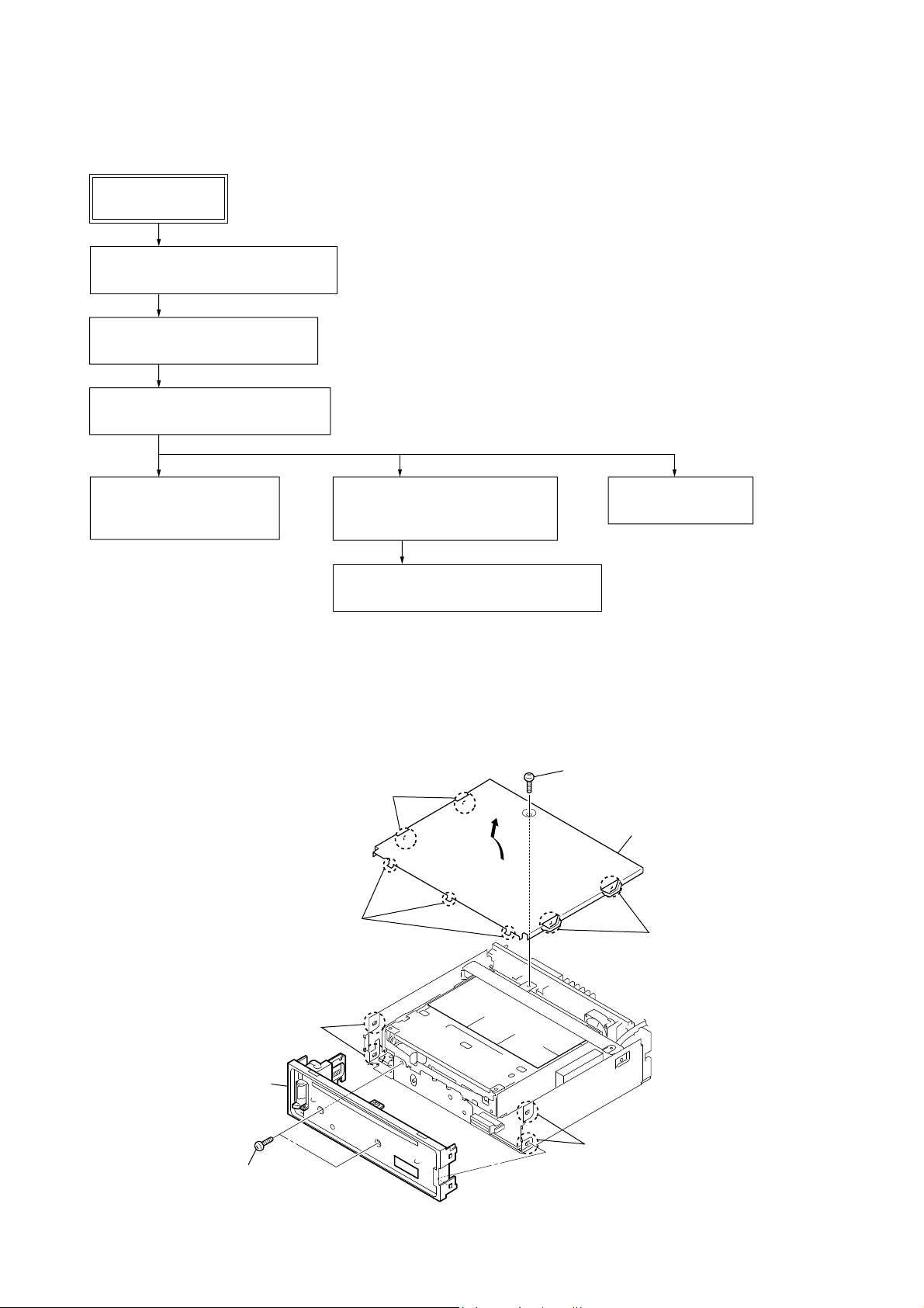
DISASSEMBLY
• This set can be disassembled in the order shown below.
3-1. DISASSEMBLY FLOW
SET
FRONT PANEL SECTION
Note: Illustration of disassembly is omitted.
3-2. SUB PANEL COMPLETE ASSY
(Page 12)
3-3. DVD MECHANISM DECK BLOCK
(Page 13)
SECTION 3
3-4. DC FAN (25X25) (M850),
MAIN BOARD
(Page 13)
Note:
Follow the disassembly procedure in the numerical order given.
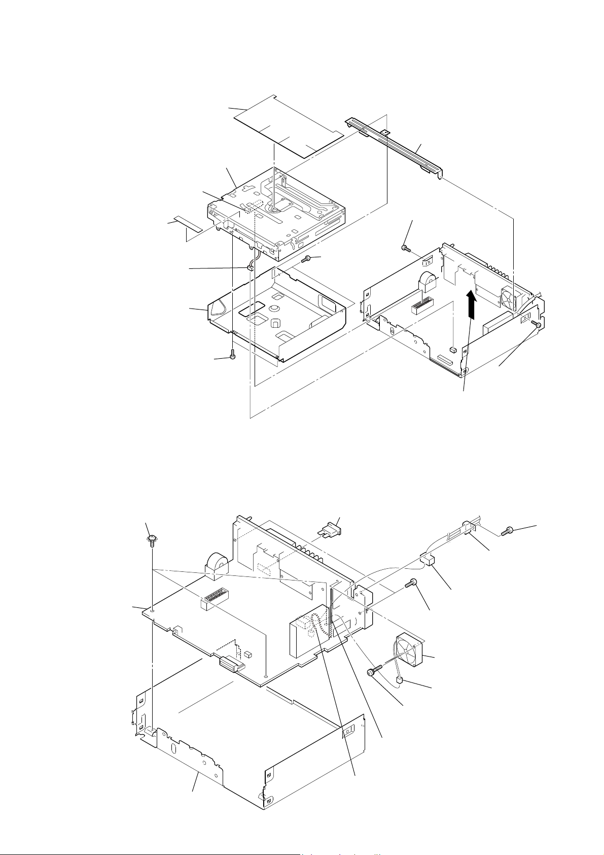
3-2. SUB PANEL COMPLETE ASSY
two bosses
three claws
3-5. CHASSIS (T612Z) SUB ASSY,
SENSOR BOARD
(Page 14)
3-6. CHASSIS (OP, ZA) COMPLETE ASSY
(Page 14)
screw
(PTT2.6 × 6)
3-7. SERVO BOARD
(Page 15)
cover block
two bosses
12
two claws
sub panel complete assy
two claws
two screws
(PTT2.6 × 6)
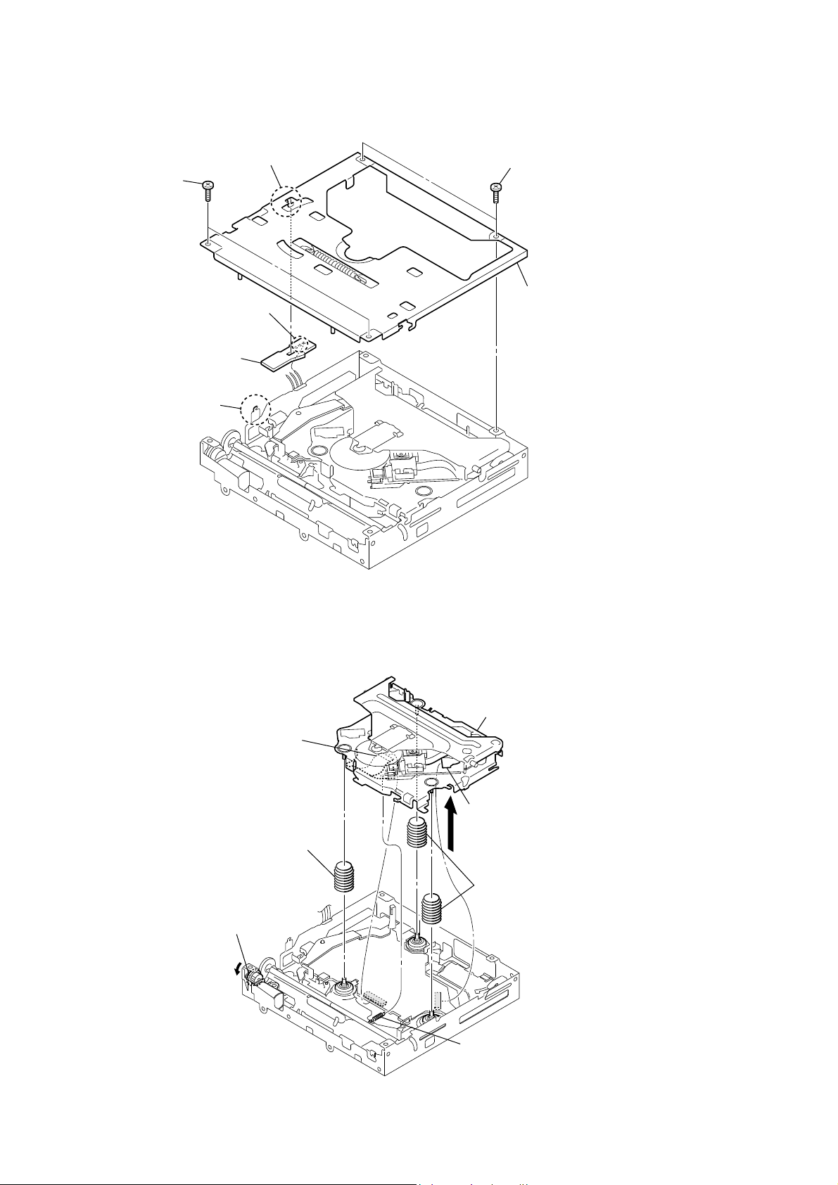
3-3. DVD MECHANISM DECK BLOCK
dust protection sheet
DVD mechanism deck block
RB
connector
(
CN3
)
laser caution label
R
connector
(
CN702
)
(612Z)
shield
two
(
PTT2.6×5
MEX-DV150UE/DV1500U/DV1505U
bracket (CD)
screw
screws
(
PTT2.6×6
)
)
two
screws
(
P1.7×2.2
)
Lift up the
(
MG-612U-187
DVD mechanism deck
3-4. DC FAN (25X25) (M850), MAIN BOARD
Note 1: If the complete MAIN board was replaced, be sure to refer to Technical News published separately.
three ground point screws
(PTT2.6 × 6)
MAIN board
RT
fuse (blade type) (auto fuse)
(10A/32V) (FU801)
connection cord for automobile
(front audio out,
rear/sub audio out)
connector
(
CN652
two
screws
(
PTT2.6×8
).
)
screw
(
PTT2.6×6
)
screw
(
PTT2.6×8
)
)
chassis
(
25×25
)
DC fan
RB
M850
(
R
(
two
screws
(
PS2.6×14
Lift up the lead pin to upper right.
Note 2: When the DC fan and MAIN board are mounted,
lock connection cord for auto mobile and wire DC fan
by push lead pin.
)
connector
CN850
)
)
13
MEX-DV150UE/DV1500U/DV1505U
3-5. CHASSIS (T612Z) SUB ASSY, SENSOR BOARD
claw
two
screws
(
P1.7×2.2
)
Remove the three solders.
SENSOR borad
claw
two
screws
(
P1.7×2.2
)
chassis (T612Z) sub assy
3-6. CHASSIS (OP, ZA) COMPLETE ASSY
flexible board
(
CN1
)
compression
Turn the gear (RA1) fully in the
direction of arrow ".
spring (damper, Z)
"
chassis (OP, ZA) complete assy
OP flexible board
(
CN2
)
two
coil springs (damper)
tension spring (KF)
14
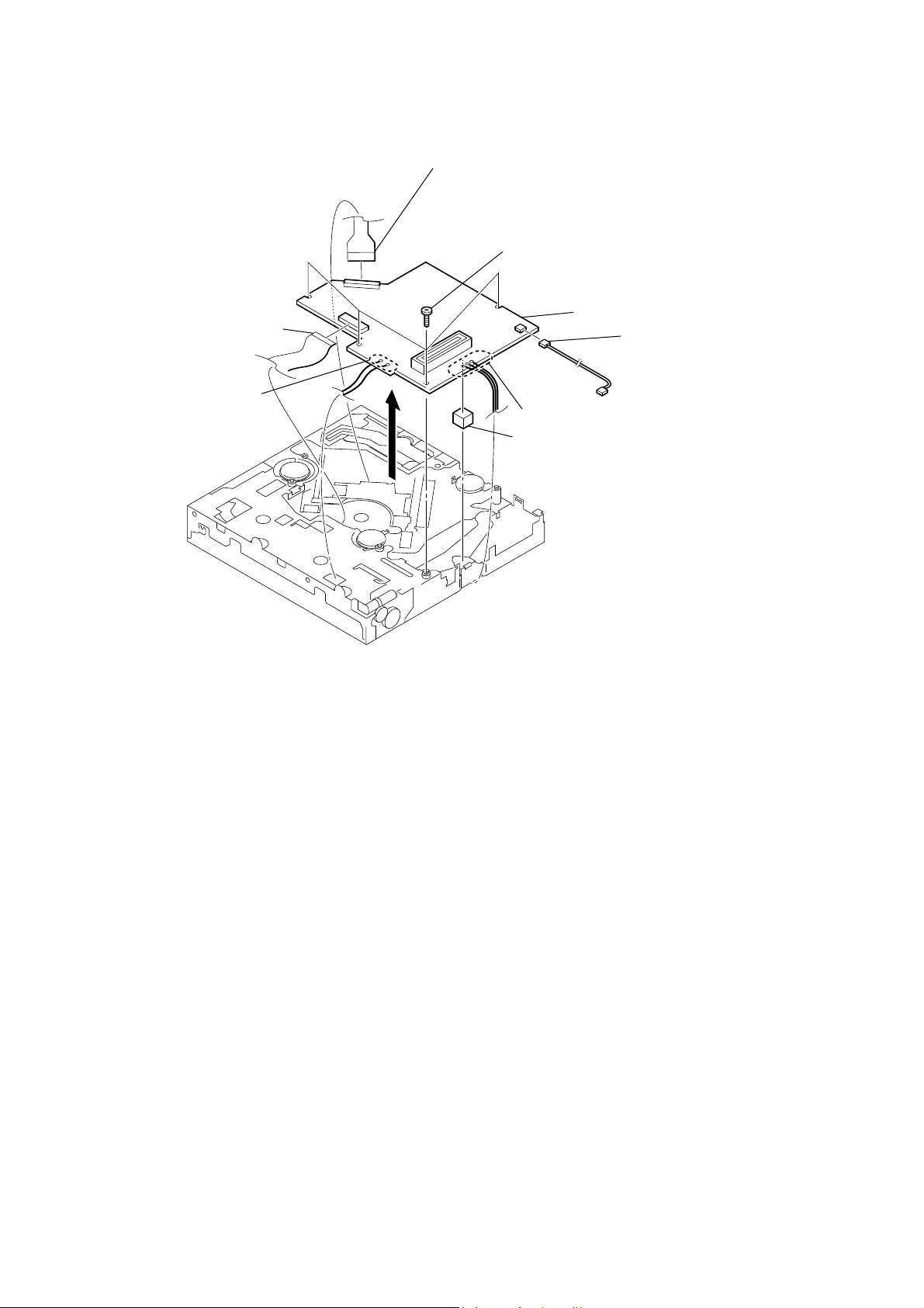
3-7. SERVO BOARD
flexible board
(
CN1
)
Remove the two solders.
MEX-DV150UE/DV1500U/DV1505U
OP flexible board
(
CN2
)
Note:
When disconnecting the OP flexible board from of the connector.
Be sure to refer to “NOTE FOR FLEXIBLE BOARD OF THE OPTICAL
PICK-UP” of the servicing notes (See page 4).
four
screws
(
M1.7×2.5
spacer(PWB7
)
SERVO board
wire
(
CN7
)
Remove the three solders.
)
– DVD mechanism deck block (Bottom view) –
15
MEX-DV150UE/DV1500U/DV1505U
ELECTRICAL CHECK
SECTION 4
SERVO SECTION
If any of the following parts was replaced, perform the “IOP
Check” as mentioned below.
• Optical pick-up block (chassis (OP, ZA) complete assy
• Mounted SERVO board
Precaution
Use the following tools and measuring devices.
• Extension jig (Part No. J-2502-062-1) between the SERVO
board and the MAIN board
• DVD test disc TDV-540C (Part No. J-2501-235-A)
• CD test disc PATD-012 (Part No. 4-225-203-01)
• Driver for adjustment
• TV moniter
• Digital voltmeter
• Oscilloscope
• Accessory remote commander RM-X168
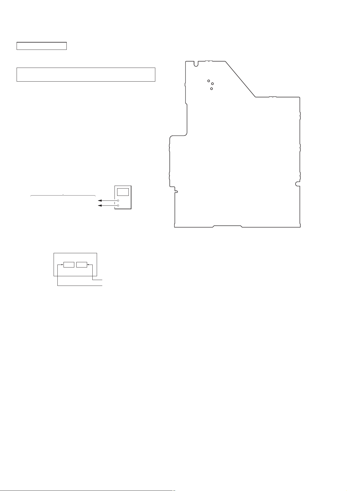
IOP CHECK
Connection:
digital voltmeter
SERVO board
TP51 (IOPDVD), TP47 (IOPCD)
TP63 (A3.3V)
+
–
Check Location:
– SERVO Board (Conductor Side) –
TP47
(IOPCD)
(A3.3V)
TP51
(IOPDVD)
TP63
Procedure:
1. Check the IOP value of DVD and CD by label on the optical
pick-up.
Optical Pick-up Label:
"
CD IOP value
DVD IOP value
2. Connect a digital voltmeter to TP51 (IOPDVD) and TP63
(A3.3V) on the SERVO board.
3. Playback the DVD test disc (TDV-540C), and make a note of
the value of digital voltmeter.
4. Divide the measured voltage value by 1, and convert it into
current value.
5. Check that the calculated value is within ±6 mA to the IOP
value given on the label.
6. Connect a digital voltmeter to TP47 (IOPCD) and TP63
(A3.3V) on the SERVO board.
7. Playback the CD test disc (PATD-012), and make a note of the
value of digital voltmeter.
8. Divide the measured voltage value by 1, and convert it into
current value.
9. Check that the calculated value is within ±6 mA to the IOP
value given on the label.
16
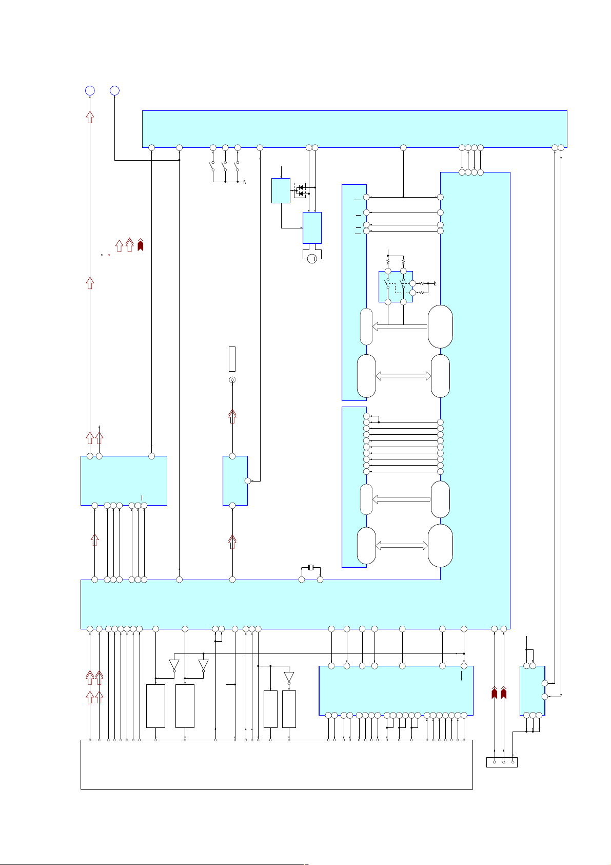
DVD PROCESSOR
OPTICAL PICK-UP BLOCK
D/A CONVERTER
(Page 18)
(Page 18)
A
B
FL
A_MUTE
IC503 (1/3)
SYSTEM CONTROLLER
MEX-DV150UE/DV1500U/DV1505U
: DVD/CD PLAY (AUDIO)
: DVD/CD PLAY (VIDEO)
: USB
SIGNAL PATH
R-ch is omitted due to same as L-ch.
15VOL
14VOR R-CH
IC6
5SCK
6DATA
2MS
52 Z_MUTE
16ZERO2
51 A_MUTE
55 DSW
53 SELFSW
SW1
SW2
(SELF)
(CHUCKING END)
PJ651
VIDEO OUT
2VOUT
IC151
VIDEO AMP
VIN
4
54 INSW
SW3
(DISC IN)
MUTE
50 VMUTE_F
+5.5V
B/U B+
IC103
REGULATOR
D103
VCC
64 EJECT
65 LOAD
IC102
LOADING
MOTOR DRIVE
RST
OE
WE
56 M_RESET
12
26
28
11
D+3.3V
45 MSTR-TX
241DUPRD1
242DUPTD1 56 MSTR-RX
248EN 57 M_CTS
247REQ 48 M_RTS
RESET#
157
MEMCS0# CE
56
MEMRD#
53
MEMWR#
32
71 USB_OVER
70 USB_ON
M
IC9
5 6
MEMADD0
1
7 3
2
MEMADD1
14, 43, 40, 37, 29
58, 57, 55, 54, 52,
49, 47, 45, 26, 24,
22, 19, 17 – 15, 13,
MEMADD0 – MEMADD20
35, 31, 27, 23, 18
51, 46, 42, 36, 33,
28, 25, 20, 48, 44, 39,
MEMDAT0 – MEMDAT15
94
93
91
90
RAMCS1
89
RAMCKE
64
PCLK
96
RAMCS0
86
RAMBA0
87
79, 83, 81, 85
77, 75, 72, 70,
69, 71, 73, 76,
RAMADD0 – RAMADD11
RAMDQM
RAMWE#
RAMCAS#
RAMRAS#
1717
M1
(LOADING)
IC11
FLASH MEMORY
1
IC10
SD-RAM
A0 – A20
25 – 18, 8 – 1,
DQ15/A-1
DQ0 – DQ14,
29, 31, 33, 35, 38,
40, 42, 44, 30, 32, 34,
DQML
15
DQMH
39
WE
16
CAS
17
RAS
18
CS
19
CKE
37
CLK
38
BA1
21
BA0
20
23 – 26,
A0 – A11
SWITCHING
48, 17, 16, 9, 10
36, 39, 41, 43, 45
29 – 34, 22, 35
SECTION 5
129AOUT0
IC4
DIAGRAMS
193 R F P
RF+
KHS-360A
5-1. BLOCK DIAGRAM - SERVO/VIDEO/USB Section -
RFN
194
RF–
134
132ABCLK 7BCK
AMCLK
196 A
198 B
A
B
131ALRCLK 8 LRCK
201 C
C
DQ0 – DQ15
2, 4, 5, 7, 8, 10,
47, 48, 50, 51, 53
TRK+
43IN2 231 TR_DRV
TRK–
11, 13, 42, 44, 45,
44IN3 237 S TA
45IN4 236 S T B
SLED MOTOR A–
SLED MOTOR A+
SLED MOTOR B+
SLED MOTOR B–
46INSP 234 SP_DRV
U2
V2
6W12
7W23
11
COIL V
COIL U
COIL W
X1
27MHz
160
Q1
Q4
159
XO
Q2
SLED/SPINDLE MOTOR DRIVE
FOCUS/TRACKING COIL DRIVE,
CD ON SWITCH
VR (CD)
XIN
42IN1 238 F O _DR V
IC1
VO1+
VO1–34VO2–31VO2+32VO3+29VO3–28VO4+26VO4–25U110V1
35
FCS–
FCS+
125IDGPCIO0 4MD
124ICGPCIO0 3MC
130AIN2
203 D
206 E
208 F
F
E
D
215 DVD_LD
Q5
AUTOMATIC POWER
CONTROL (FOR DVD)
LD (DVD)
Q12
138AMUTE
214 C D _LD
Q3
CONTROL (FOR CD)
AUTOMATIC POWER
LD (CD)
181DAC6 (CVBS)
213 DVD_MD
212 CD_MD
137 HOME
209 V C
222 CD_DVD
221 OP_GAIN
Q11
VC
DVD ON SWITCH
PD
VC
GSW
MSW
VR (DVD)
LIMIT SWITCH
110, 114, 116, 119
98, 101, 104, 106,
108, 105, 102, 100
120, 118, 115, 112,
246 F G
47FG
HU–15HV+16HV–17HW+18HW–19HB
HU+
14
HALL V– (H2–)
HALL U– (H1–)
HALL V+ (H2+)
HALL U+ (H1+)
RAMDAT0 – RAMDAT15
HALL W– (H3–)
HALL W+ (H3+)
244 DRV_XSTBY
24
STBY
13
HALL_BAIS–
CN902
USBDP
66
D+D–VBUS
3
(USB)
USBDN
67
USB+5V
2
IN
IC402
OUT
USB POWER CONTROL
6
2
1
3OUT
IN
7
4 5
/EN /DC
8OUT
MEX-DV150UE/DV1500U/DV1505U
h.
CN652
REAR/SUB
AUDIO OUT
(FRONT AUDIO OUT)
(L)
(L)
4
(R)
(R)
1
3
6
R-CH
R-CH
FL+
1
CN801 (1/2)
5
FL RR+
IC802 (1/2)
POWER AMP
9
12 FL IN_RR
FL–
3
FL RR–
RL+
RR+
FR+
FR–
4
2
12
R-CH
RL RF+ 9
11 IN_RF
RR–
RL–
3
11
10
R-CH
7
STB
22
DIAG
RL RF–
25
ACGND
16
SCL
4
SDA
SCL
2
SDA
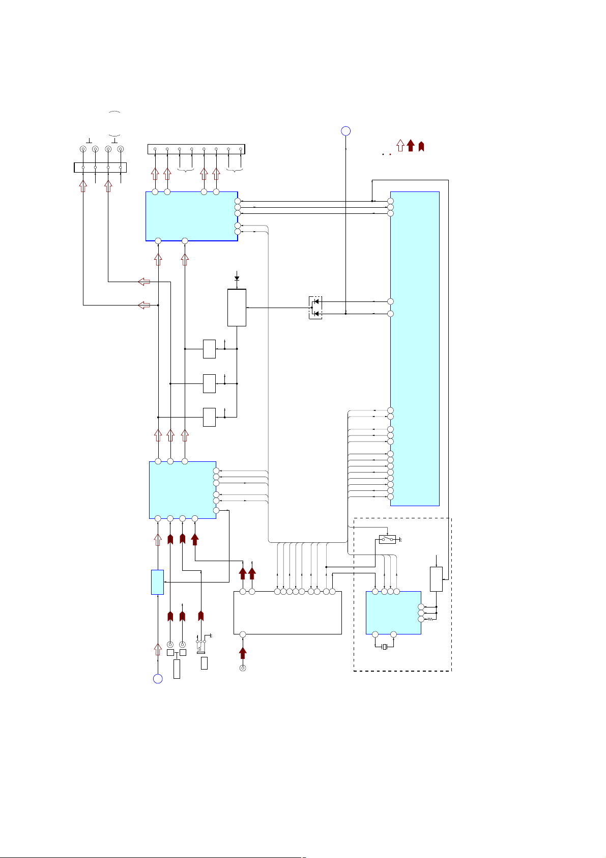
(Page 17)
B
A_MUTE
: DVD/CD PLAY (AUDIO)
: TUNER (FM/AM)
: AUX IN
SIGNAL PATH
R-ch is omitted due to same as L-c
STB
25
DIAG
57
BEEP
26
B/U B+
D361
ATT
49
A_MUTE
51
IC503 (2/3)
SYSTEM CONTROLLER
Q354
MUTING
Q358
MUTING
R-CHR-CH
R-CH
MUTING
CONTROL SWITCH
Q361, 362
D504
IC302
INPUT SELECTOR,
AUDIO PROCESSOR
2DVD-L
IC301
LINE AMP
FL
A
30FL34
SUB-L
9 RAUX-L
L
PJ601
AUX IN
34
RL
12 FAUX-L
R-CH
R
SDA
12
SDA
X201
20
22
34
33
82
18
19
17
23
84
83
27
28
SCL
SCL 11
8.664MHz
EECKO
EESIO
SA_CLK
SA_DATA
SA_IN
TUNATTIN
TUNATT
DAVN
NSMASK
QUALITY
VSM
I2CCKO
I2CSIO
CONTROL SWITCH
TUNER NOISE MASK
DAVN
15
INTN
VDDA
VDDD
RESETN
XTI
9
Q202
1
7
8
B/U+3.3V
Q203, 204
B+ SWITCH
(DV150UE/DV1500U: AEP, UK)
1818
TRCL
9
RDS
TRDA
SACLK
SADA
SAOUT
MUTE CON
TU MUTE
DAVN
NSMASK
QUALITY
VSM
SCL
SDA
NSMASK
16
MPX
IC201
RDS DECODER
XTO
10
Q352
MUTING
CLK
27
DATA
28
SOUT
29
SCL
37
SDA
38
FIL
40
4TU-L
TUX201
TUNER UNIT
R-CH
AUX
J901
J201
SACLK
SADA
SAOUT
SCL
SDA
SCL
SDA
VSM
TRCL
6
13
TU_SCL
S_METER
TU MUTE
TRDA
MUTE CON
7
8
17
16
E2P_SCL
E2P_SDA
TU_MUTE
MUTE-CONDITION
QUALITY
5
QUALITY
R-CH
3
L
ANT
1 4
(ANTENNA IN)
14
R
TU_SDA
5-2. BLOCK DIAGRAM - TUNER/AUDIO Section -
(Page 17)
MEX-DV150UE/DV1500U/DV1505U
MEX-DV150UE/DV1500U/DV1505U
 Loading...