

Sony MEX-BT5000 Service Manual
MEX-BT5000
SERVICE MANUAL
Ver. 1.0 2006.06
US and foreign patents licensed from Dolby
Laboratories.
Manufactured under license
R
from BBE Sound, Inc.
improves digitally compressed sound, such as
The BBE MP process
MP3, by restoring and enhancing the higher
harmonics lost through compression. BBE MP
works by generating even-order harmonics from
the source material, effectively recovering
warmth, detail and nuance.
The “SAT Radio Ready”
logo indicates that this
product will control a
satellite radio tuner module
(sold separately). Please see your nearest
authorized Sony dealer for details on the
satellite radio tuner module.
“SAT Radio,” “SAT Radio Ready,” the SAT
Radio and SAT Radio Ready logos and all
related marks are trademarks of Sirius Satellite
Radio Inc. and XM Satellite Radio Inc.
The Bluetooth word mark and logos are owned
by the Bluetooth SIG, Inc. and any use of such
marks by Sony Corporatio n is under license.
Other trademarks and tr ade names are those of
their respective owners.
SonicStage and it s logo are trademar ks of Sony
Corporation.
“ATRAC” and are trademarks of
Sony Corporation.
Microsoft, Windows Media,
and the Windows logo are
trademarks or registered
trademarks of Microsoft
Corporation in the United States and/or other
countries.
AUDIO POWER SPECIFICATIONS
(US, Canadian only)
POWER OUTPUT AND TOTAL HARMONIC
DISTORTION
23.2 watts per channel minimum continuous
average power into 4 ohms, 4 channels driven
from 20 Hz to 20 kHz with no more than 5% total
harmonic distortion.
CEA2006 Standard
Power Output: 17 Watts RMS × 4 at
4 Ohms < 1% THD+N
SN Ratio: 82 dBA
(reference: 1 Watt into 4 Ohms)
CD Player section
Signal-to-noise ratio: 120 dB
Frequency response: 10 − 20,000 Hz
Wow and flutter: Below measurable limit
Tuner section (US, Canadian)
FM
Tuning range: 87.5 − 107.9 MHz
Antenna terminal: External antenna connector
Intermediate frequency: 10.7 MHz/450 kHz
Usable sensitivity: 9 dBf
Selectivity: 75 dB at 400 kHz
Signal-to-noise ratio: 67 dB (stereo), 69 dB (mono)
Harmonic distortion at 1 kHz: 0.5 % (ste reo),
0.3 % (mono)
Separation: 35 dB at 1 kHz
Frequency response: 30 − 15,000 Hz
AM
Tuning range: 530 − 1,710 kHz
Antenna terminal: External antenna connector
Intermediate frequency: 10.7 MHz/450 kHz
Sensitivity: 30 µV
US Model
Canadian Model
AEP Model
UK Model
E Model
Model Name Using Similar Mechanism MEX-1GP
CD Mechanism Type MG-611WA-186//Q
Optical Pick-up Name KSS1000E
SPECIFICATIONS
Tuner section (AEP, UK)
FM
Tuning range: 87.5 − 108 MHz
Aerial terminal: External aerial connector
Intermediate frequency: 10.7 MHz/450 kHz
Usable sensitivity: 9 dBf
Selectivity: 75 dB at 400 kHz
Signal-to-noise ratio: 67 dB (stereo), 69 dB (mono)
Harmonic distortion at 1 kHz: 0.5 % (stereo),
0.3 % (mono)
Separation: 35 dB at 1 kHz
Frequency response: 30 − 15,000 Hz
MW/LW
Tuning range:
MW: 531 − 1,602 kHz
LW: 153 − 279 kHz
Aerial terminal: External aerial connector
Intermediate frequency: 10.7 MHz/450 kHz
Sensitivity: MW: 30 µV, LW: 40 µV
Tuner section (E)
FM
Tuning range:
87.5 − 108.0 MHz (at 50 kHz step)
87.5 − 107.9 MHz (at 200 kHz step)
FM tuning interval: 50 kHz/200 kHz switchable
Aerial terminal: External aerial connector
Intermediate frequency: 10.7 MHz/450 kHz
Usable sensitivity: 9 dBf
Selectivity: 75 dB at 400 kHz
Signal-to-noise ratio: 67 dB (stereo), 69 dB (mono)
Harmonic distortion at 1 kHz: 0.5 % (stereo),
0.3 % (mono)
Separation: 35 dB at 1 kHz
Frequency response: 30 − 15,000 Hz
AM
Tuning range:
531 − 1,602 kHz (at 9 kHz step)
530 − 1,710 kHz (at 10 kHz step)
AM tuning interval: 9 kHz/10 kHz switchable
Aerial terminal: External aerial connector
Intermediate frequency: 10.7 MHz/450 kHz
Sensitivity: 30 µV
– Continued on next page –
9-887-268-01
2006F05-1
© 2006.06
BLUETOOTH AUDIO SYSTEM
Sony Corporation
eVehicle Division
Published by Sony Techno Create Corporation

MEX-BT5000
Wireless Communication
Communication System:
Bluetooth Standard version 2.0
Output:
Bluetooth Standard Power Class 2 (Max. +4 dBm)
Maximum communication range:
Line of sight approx. 10 m (32.8 ft)*
Frequency band:
2.4 GHz band (2.4000 − 2.4835 GHz)
Modulation method: FHSS
Compatible Bluetooth Pr ofiles*
A2DP (Advanced Audio Distribution Profile)
AVRCP (Audio Video Remote Control Profile)
HFP (Handsfree Profile)
OPP (Object Push Profile)
*1
The actual range will vary depending on factors
such as obstacles between devices, magnetic
fields around a microwave oven, static electricity,
reception sensitivity, antenna's perfomance,
operating system, software application, etc.
*2
Bluetooth standard profiles indicate the purpose of
Bluetooth communication between devices.
Power amplifier section
Outputs: Speaker outputs (sure seal connectors)
Speaker impedance: 4 ñ 8 ohms
Maximum power output: 52 W × 4 (at 4 ohms)
General
Outputs:
Audio outputs terminal (front/rear)
Subwoofer output te r minal (mono)
Power antenna relay control terminal
Power amplifier control terminal
Inputs:
Telephone ATT control terminal
Illumination control te rm inal
BUS control input terminal
BUS audio input/AUX IN terminal
Remote controlle r input terminal
Antenna input terminal
Tone controls:
Low: ±10 dB at 60 Hz or 100 Hz (XPLOD)
Mid: ±10 dB at 500 Hz or 1 kHz (XPLOD)
High: ±10 dB at 10 kHz or 12.5 kHz (XPLOD)
Power requirements: 12 V DC car battery
(negative ground)
Dimensions: Approx. 178 × 50 × 183 mm
1
(7
/8 × 2 × 71/4 in) (w/h/d)
Mounting dimensions: Approx. 182 × 53 × 162 mm
1
(7
/4 × 21/8 × 61/2 in) (w/h/d)
Mass: Approx. 1.2 kg (2 lb 11 oz)
Supplied accessories:
Card remote commander:
Parts for installation and co nnections (1 set)
Your dealer may not handle some of the above listed
accessories. Ple as e ask the dealer for detailed
information.
MPEG Layer-3 audio coding technology and
patents licensed from Fraunhofer IIS and Thomson.
Note
This unit cannot be connected to a digital preamplifier
or an equalizer which is Sony BUS system compatible.
Design and specifications are subject to change
without notice.
1
2
:
RM-X301 (US, Canadian)
RM-X302 (AEP, UK)
RM-X303 (E)
• AEP, UK, E model
CAUTION
Use of controls or adjustments or performance of procedures
other than those specified herein may result in hazardous radiation
exposure.
Notes on chip component replacement
• Never reuse a disconnected chip component.
• Notice that the minus side of a tantalum capacitor may be
damaged by heat.
Flexible Circuit Board Repairing
• Keep the temperature of the soldering iron around 270 ˚C
during repairing.
• Do not touch the soldering iron on the same conductor of the
circuit board (within 3 times).
• Be careful not to apply force on the conductor when soldering
or unsoldering.
2
This label is located on the bottom of the
chassis.
CAUTION – CLASS 1M INVISIBLE LASER RADIATION
WHEN OPEN.
DO NOT VIEW DIRECTLY WITH OPTICAL INSTR UMENTS.
SAFETY-RELATED COMPONENT WARNING!!
COMPONENTS IDENTIFIED BY MARK 0 OR DOTTED LINE
WITH MARK 0 ON THE SCHEMATIC DIAGRAMS AND IN
THE PARTS LIST ARE CRITICAL TO SAFE OPERATION.
REPLACE THESE COMPONENTS WITH SONY PARTS WHOSE
PART NUMBERS APPEAR AS SHOWN IN THIS MANUAL OR
IN SUPPLEMENTS PUBLISHED BY SONY.

TABLE OF CONTENTS
1. SERVICING NOTES ............................................... 4
2. GENERAL ................................................................... 6
3. DISASSEMBLY
3-1. Disassembly Flow ........................................................... 16
3-2. Front Back Panel Assy .................................................... 16
3-3. KEY Board ...................................................................... 17
3-4. Sub Panel Assy ................................................................ 17
3-5. CD Mechanism Block (MG-611WA-186//Q) ................. 18
3-6. MAIN Board.................................................................... 18
3-7. ANTENNA Board, IT Board .......................................... 19
3-8. Chassis (T) Sub Assy....................................................... 19
3-9. Roller Arm Assy .............................................................. 20
3-10. Chassis (OP) Assy ........................................................... 20
3-11. Optical Pick-up (KSS1000E) .......................................... 21
3-12. SL Motor Assy (Sled) (M902)......................................... 21
3-13. LE Motor Assy (B) (Loading) (M903) ............................ 22
3-14. SERVO Board.................................................................. 22
MEX-BT5000
4. TEST MODE.............................................................. 23
5. DIAGRAMS
5-1. Block Diagram – CD SERVO Section – ......................... 24
5-2. Block Diagram – BLUETOOTH Section –..................... 25
5-3. Block Diagram – AUDIO Section – ................................ 26
5-4. Block Diagram – DISPLAY/MAIN Section – ................ 27
5-5. Block Diagram – POWER SUPPLY Section – ............... 28
5-6. Schematic Diagram – SERVO Section (1/2) –................ 30
5-7. Schematic Diagram – SERVO Section (2/2) –................ 31
5-8. Printed Wiring Boards – SERVO Section – .................... 32
5-9. Printed Wiring Board – IT Board – ................................. 33
5-10. Schematic Diagram – IT Board (1/2) – ........................... 34
5-11. Schematic Diagram – IT Board (2/2) – ........................... 35
5-12. Printed Wiring Board
– MAIN Board (Component Side) – ............................... 36
5-13. Printed Wiring Board
– MAIN Board (Conductor Side) – ................................. 37
5-14. Schematic Diagram – MAIN Board (1/3) – .................... 38
5-15. Schematic Diagram – MAIN Board (2/3) – .................... 39
5-16. Schematic Diagram – MAIN Board (3/3) – .................... 40
5-17. Printed Wiring Board – SUB Board – ............................. 42
5-18. Schematic Diagram – SUB Board – ................................ 43
5-19. Schematic Diagram – KEY Board (1/2) – ....................... 44
5-20. Schematic Diagram – KEY Board (2/2) – ....................... 45
5-21. Printed Wiring Board – KEY Board –............................. 46
6. EXPLODED VIEWS
6-1. General Section ............................................................... 67
6-2. Front Panel Section ......................................................... 68
6-3. CD Mechanism Deck Section-1 (MG-611WA-186//Q) .. 69
6-4. CD Mechanism Deck Section-2 (MG-611WA-186//Q) .. 70
6-5. CD Mechanism Deck Section-3 (MG-611WA-186//Q) .. 71
6-6. CD Mechanism Deck Section-4 (MG-611WA-186//Q) .. 72
7. ELECTRICAL PARTS LIST................................ 73
3
MEX-BT5000
SECTION 1
SERVICING NOTES
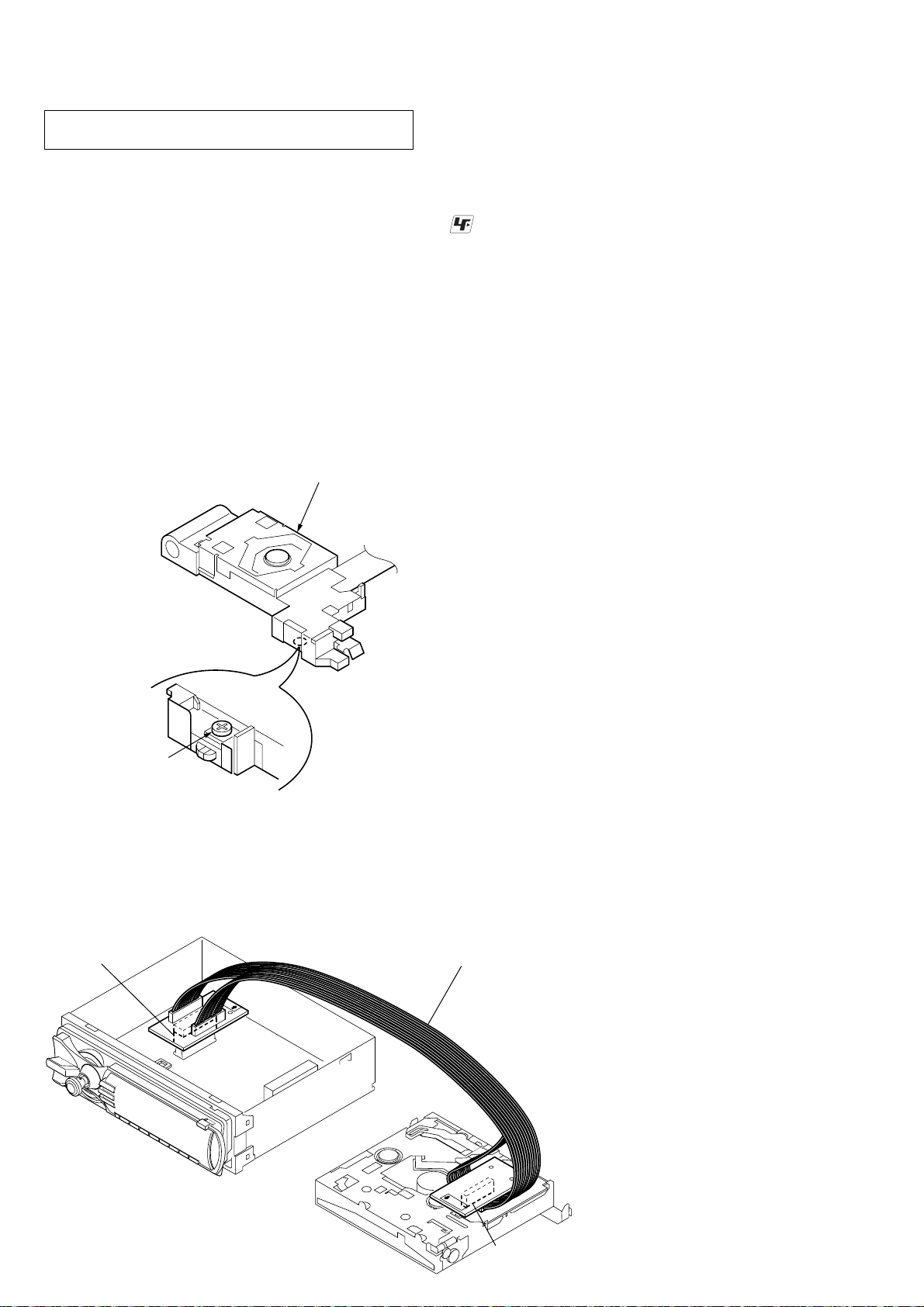
NOTES ON HANDLING THE OPTICAL PICK-UP
BLOCK OR BASE UNIT
The laser diode in the optical pick-up block may suffer electrostatic
break-down because of the potential difference generated by the
charged electrostatic load, etc. on clothing and the human body.
During repair, pay attention to electrostatic break-down and also
use the procedure in the printed matter which is included in the
repair parts.
The flexible board is easily damaged and should be handled with
care.
NOTES ON LASER DIODE EMISSION CHECK
Never look into the laser diode emission from right above when
checking it for adjustment. It is feared that you will lose your sight.
If the optical pick-up block is defective, please replace the whole
optical pick-up block.
Never turn the semi-fixed r esistor located at the side of optical pickup block.
optical pick-up
UNLEADED SOLDER
Boards requiring use of unleaded solder are printed with the leadfree mark (LF) indicating the solder contains no lead.
(Caution: Some printed circuit boards may not come printed with
the lead free mark due to their particular size)
: LEAD FREE MARK
Unleaded solder has the following characteristics.
• Unleaded solder melts at a temperature about 40 ˚C higher
than ordinary solder.
Ordinary soldering irons can be used but the iron tip has to be
applied to the solder joint for a slightly longer time.
Soldering irons using a temperature regulator should be set to
about 350 ˚C.
Caution: The printed pattern (copper foil) may peel away if
the heated tip is applied for too long, so be careful!
• Strong viscosity
Unleaded solder is more viscou-s (sticky, less prone to flow)
than ordinary solder so use caution not to let solder bridges
occur such as on IC pins, etc.
• Usable with ordinary solder
It is best to use only unleaded solder but unleaded solder may
also be added to ordinary solder.
semi-fixed resistor
EXTENSION CABLE AND SERVICE POSITION
When repairing or servicing this set, connect the jig (extension cable)
as shown below.
• Connect the MAIN board (CNP501) and the SERVO board
(CN2) with the extension cable (Part No. J-2502-076-1).
MAIN board
(CNP501)
extension cable
(J-2502-076-1)
SERVO board
4
(CN2)
MEX-BT5000
y
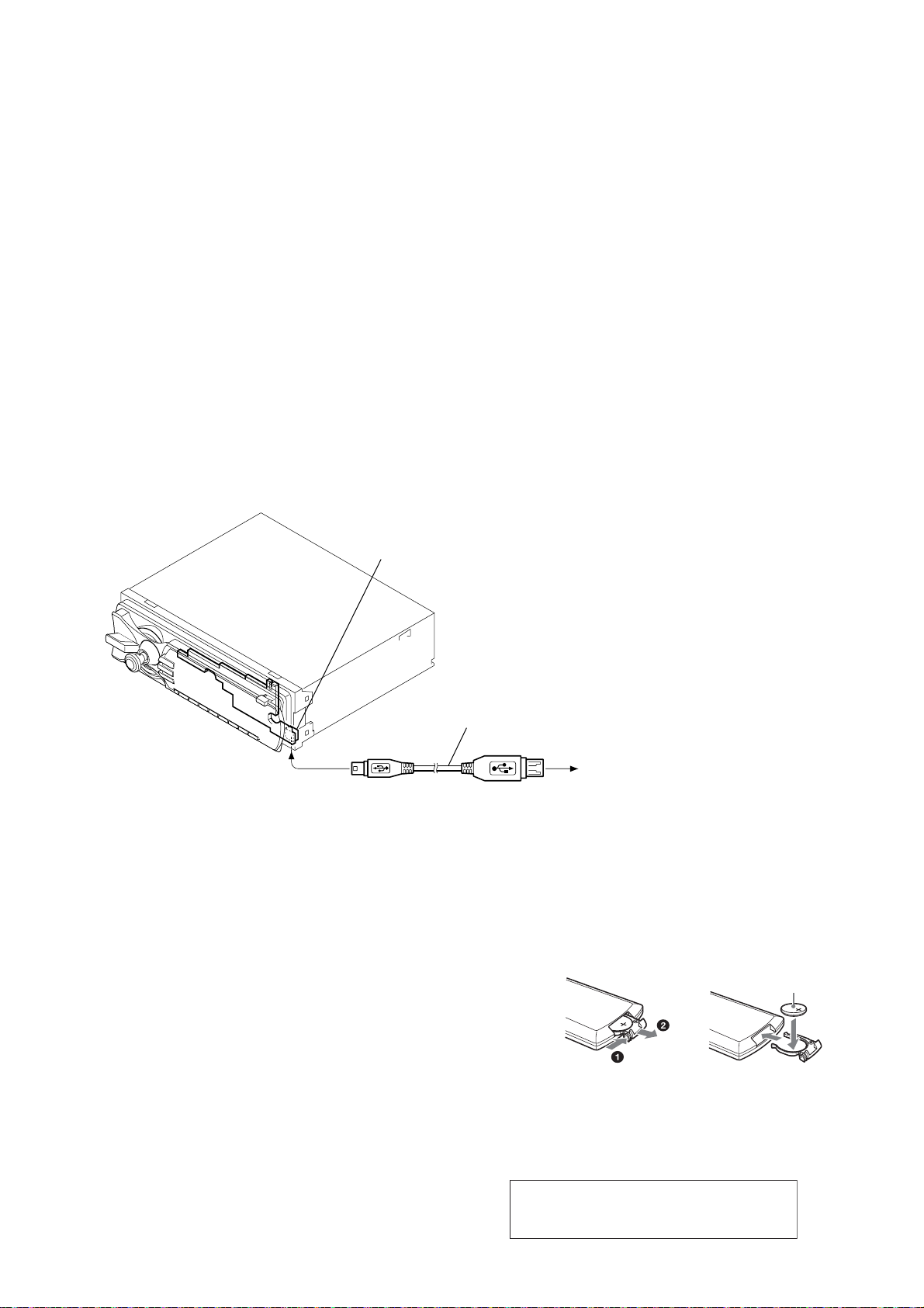
REPLACING THE LITHIUM BATTERY OF THE CARD
REMOTE COMMANDER
Under normal conditions, the battery wil l last approximately 1 year.
(The service life may be shorter, depending on the conditions of use.)
When the battery becomes weak, the range of the card remote commander
becomes shorter. Replace the battery with a new CR2025 lithium battery.
Use of any other battery may present a risk of fire or explosion.
Notes on the lithium battery
•
Keep the lithium battery out of the reach of children.
Should the battery be swallowed, immediately consult a doctor.
•
Wipe the battery with a dry cloth to assure a good contact.
•
Be sure to observe the correct polarity when installing the battery.
•
Do not hold the battery with metallic tweezers, otherwise a short-circuit may
occur.
c
+ side up
WARNING
Battery may explode if mistreated.
Do not recharge, disassemble, or dispose of in fire.
THE VERSION UP OF THE FIRMWARE
To secure the connectivity with the new cellular phone etc. put on
the market after this machine is put on the market, the upgrade in
service is done.
Procedure:
1. The USB memory is prepared, and the firmware is downloaded
to the USB memory. (The USB memory is a thing to prepare
the one of about 64MB made of SONY POCKET BIT.)
2. Power supply of the set is turned off.
3. Press the [4] t [5] t [6] ([6] is pressed for two seconds)
button of the set sequentially, and enter the service mode.
4. Wait for 1 minute after executing step 3, the set is connected
with the USB memory with connected the USB cable (Part.
No. J-2502-103-1) as shown in Fig.1.
5. Wait for 1 minute (time untill access LED of USB memory
disappears) after executing step 4, push the joystick for two
seconds of the set, and the version up confirmation screen is
displayed.
6. Select “Y es” by using the UP/DOWN of joystick, and conf irm
the displayed version number, and push the joystick.
7. The version up is executed. When the version up ends, reset is
automatically done, and usual screen of power off state is
displayed.
SUB board
(CN903)
RELEASING THE DISC SLOT LOCK
The disc slot lock function for the antitheft of an demonstration
disc in the store is equipped.
Releasing Procedure :
1. Power supply is turned off.
2. Enter the Jog daial to the left, and enter the Jog daial to the
right, and press the [1] t [2] ([2] is pressed for tw o seconds)
button of the set sequentially, and disc slot is unlocked.
SECURITY
To lock the personal information in the following menus by setting
a 4-digit password.
“Dialed Calls,” “Received Calls,” “Phonebook,”
“Preset Dial,” “Receive PB”
If you set the security, “Security Locked” appears when the above
menus are operated.
To unlock the security, select “Unlock” and input the password
number.
TEST DISCS
Use following TEST DISC whan this set confirms the operation
and checks it.
3-702-101-01 YEDS-18 (for CD)
4-225-203-01 PATD-012 (for CD)
J-2502-063-1 TCD-R082LMT (for CD-R)
Fig.1 Method to connect the set with USB memory
FACTORY SHIPMENT MODE
Even if the set is reset, bluetooth system menu setting, connected
registration equipment, and telephone book function, etc. recorded
in tha flash memory are not initialized. It is necessary to execute
factory shipment mode to initialize them.
Procedure:
1. Turn off the setting of the bluetooth signal, and po wer supply
is turned off.
2. Press the [4] t [5] t [1] ([1] is pressed for two seconds)
button of the set sequentially, and enter the test mode.
3. Press the [1] button for two seconds of the set, and the DAIG
information is initialized.
4. Press the [6] button for two seconds of the set, and the bluetooth
setting item preserved in NOR FLASH is initialized.
5. Press the [OFF] button of the set, and the test mode is made
clear. At this time, the memory of the tuner is initialized.
6. The power supply code is removed and the power supply is
turned off, and the power supply will be turned on again in
one minute. At this time, the tuner preset, and EQ3 setting
value, etc. are initialized.
USB cable
(Part.No. J-2502-103-1)
USB memor
5

MEX-BT5000
(US, Canadian)
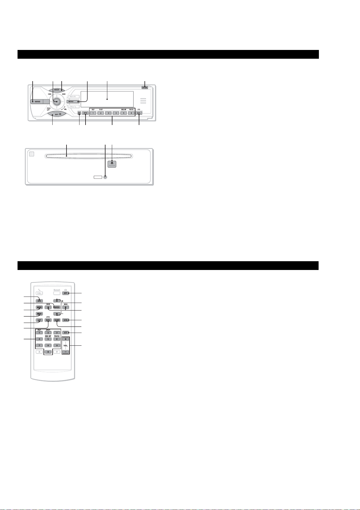
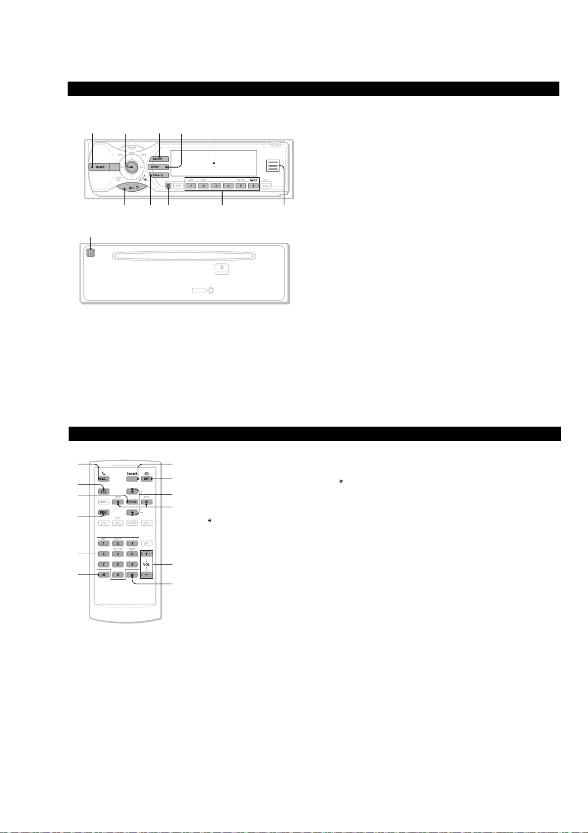
Location of controls and basic operations
Audio function
Main unit
1
Front panel removed
35624
79 qa0
8
RESET
SECTION 2
GENERAL
Refer to the pages listed for details. The
corresponding buttons on the card remote
commander control the sam e functions as those
on the unit.
A SOURCE button
To p owe r on; change the source (Radio/CD/
1
MD*
/Bluetooth AUDIO/AUX/SAT*2).
B Joystick/LIST button
Rotate to: Adjust the volume.
Push up/down/left/right to: Select a menu
item.
Press to: Apply a setting.
1
CD/MD*
:
Push up/down to*
MEX-BT5000
qfqdqs
− Skip groups*
− Skip groups*
(push and hold).
Push left/right to:
− Skip tracks (push).
− Skip tracks continuously (push, then push
again within about 2 seco nds and hold).
− Reverse/fast-forward a track (push and
hold).
Radio:
Push up/down to:
− Receive sto r ed station.
Push left/right to:
− Tune in stations autom atically (push).
− Find a station manually (push and hold).
Press to:
− Display the list.
− Display the category list*
3
:
4
/albums*5 (push).
4
/albums*5 continuously
2
.
This section is extracted from
instruction manual.
C MODE button
To select the radio band (FM/AM)/ select the
SAT tuner band (mode)*
D MENU button
To enter menu.
E Display window
F OPEN button
G OFF button
To power off; sto p the source.
H Receptor for the card rem ote
commander
2
/select the unit*6.
Card remote commander RM-X301
1
qg
3
4
qh
qa
qj
I SCRL (scroll) button
To scroll the display item.
J Number buttons
7
qk
ql
9
w;
wa
K DSPL (display) button
ws
L Disc slot
M RESET button
N Z (eject) button
The following buttons on the card remote
commander have also different buttons/functions
from the unit.
1
:
CD/MD*
(1): REP
(2): SHUF
(5): BBE MP*
(6): PAUS E*
Radio:
To receive stored stations (press); store
stations (press and hold).
To chan g e display items.
To insert the disc.
To eject the disc.
7
To a ctivate the BBE MP function, set
“BBE MP on.” To cancel, set “BBE MP
off.”
7
To p ause playback. To cancel, press
again.
qg ENTER button
To apply a setting.
qh LIST/CAT*
qj Number buttons
qk M (+)/m (–) buttons
ql < (.)/, (> ) buttons
w; SOUND button
wa ATT (attenuate) button
ws VOL (volume) +/– buttons
*1
When an MD changer is connected.
*2
When the SAT tuner is connected.
*3
If the changer is connected, the operation is
different.
*4
When an ATRAC CD is played.
*5
When an MP3/WMA is played.
*6
When a CD/MD changer is connected.
*7
When playing back on this unit.
2
To list up.
Buttons 1 to 6 share the same functions as
the number buttons on the unit.
The same as pushing the joystick up/down.
The same as pushing the joystick left/right.
To select sound items.
To atte nuate the sound. To cancel, press
again.
To adjust volume.
button
Note
If the unit is turned off and the display
disappears, it cannot be operated with the card
remote commander unless
is pressed, or a disc is inserted to activate the unit
first.
Tip
For details on how to replace the battery, see
“Replacing the lithium battery of the card remote
commander”.
(SOURCE)
on the unit
6

MEX-BT5000
Bluetooth function
Main unit
1
697
Front panel removed
qa
3524
8
RESET
MEX-BT5000
0
Refer to the pages listed for details. The
corresponding buttons on the card remote
commander control the same functions as thos e
on the unit.
A SOURCE button
To p owe r on; change the source (Radio/CD/
1
MD*
/Bluetooth AUDIO/A UX/SAT*2).
B Joystick
Rotate to: Adjust the volume.
Push up/down/left/right to: Select a menu
item.
Press to: Apply a setting.
Bluetooth audio device*
Push left/right to:
− Skip tracks (push).
− Reverse/fast-forward a track (push and
hold).
C Bluetooth button
To a ccess the Bluetooth functions; receive a
call.
3
:
D MENU button
To enter menu; receive a call.
E Display window
F OFF button
To power off; stop the source; end or reject a
call.
G CALL button
To access the telephone functions; receive a
call.
H Receptor for the card rem ote
commander
I Number buttons
To call st ored dials.
Bluetooth audio device*
(6): PAUSE
To p ause playback.
J Bluetooth indicator
Lights up when the Bluetooth signal is input/
output. Goes of f when the B luetooth signal is
off.
K Microphone
3
:
Card remote commander RM-X301
73
1
qs
4
The following buttons on the card remote
commander have also different b utton s/funct ions
from the unit.
qs ENTER button
6
qg
qh
To apply a setting.
qd Number buttons
To input numbers (phone number, passcode,
etc.).
Buttons 1 to 6 share the sam e functions as
the number buttons on the unit.
qf
button
qg M (+)/m (–) buttons
The same as pushing the joystick up/down.
qd
qj
qf
qk
qh < (.)/, (> ) buttons
The same as pushing the joystick left/right.
qj VOL (volume) +/– buttons
To adjust volume.
button
qk
*1
When an MD changer is connected.
*2
When the SAT tuner is connected.
*3
When a Bluetooth audio device (supports AVRCP
of Bluetooth technology) is connected. Depending
on the device, certain operations may not be
available.
Note
If the unit is turned off and the display
disappears, it cannot be operated with the card
remote commander unless
unit is pressed, or a disc is inserted to activate
the unit first.
Tip
For details on how to replace the battery, see
“Replacing the lithium battery of the card remote
commander”.
(SOURCE)
on the
7
MEX-BT5000
(AEP, UK)
Location of controls and basic operations
Audio function
Main unit
1
Front panel removed
35624
79 qa0
8
RESET
Refer to the pages listed for details. The
corresponding buttons on the card remote
commander control the same functions as those
on the unit.
A SOURCE button
To p owe r on; change the source (Radio/CD/
1
MD*
/Bluetooth AUDIO/A UX).
B Joystick/LIST button
Rotate to: Adjust the volume.
Push up/down/left/right to: Select a menu
item.
Press to: Apply a setting.
1
CD/MD*
:
Push up/down to*
MEX-BT5000
qfqdqs
− Skip groups*
− Skip groups*
(push and hold).
Push left/right to:
− Skip tracks (push).
− Skip tracks continuously (push, then push
again within about 2 seco nds and hold).
− Reverse/fast-forward a track (push and
hold).
2
:
3
/albums*4 (push).
3
/albums*4 continuously
Radio:
Push up/down to:
− Receive stored station.
Push left/right to:
− Tune in stations autom atically (push).
− Find a station manually (push and hold).
Press to:
− Display the list.
C MODE button
To select the radio band (FM/MW/LW)/
select the unit*
D MENU button
To enter menu.
E Display window
F OPEN button
OFF button
To power off; stop the sourc e.
H Receptor for the card rem ote
commander
5
.
Card remote commander RM-X302
1
qg
3
4
qh
qa
qj
7
qk
ql
w;
wa
ws
wd
I AF (Alternative Frequencies)/TA
(Traffic Announcement) button
To set A F and TA in RDS.
J Number buttons
K DSPL (display)/PTY (Programme
L Disc slot
M RESET button
N Z (eject) button
The following buttons on the card remote
commander have also different buttons/functions
from the unit.
1
CD/MD*
:
(1): REP
(2): SHUF
(5): BBE MP*
(6): PAUS E*
Radio:
To receive stored stations (press); store
stations (press and hold).
Type) button
To change di splay items; select PTY in RDS.
To insert the disc.
To eject the disc.
6
To a ctivate the BBE MP function, set
“BBE MP on.” To cancel, set “BBE MP
off.”
6
To p ause playback. To cancel, press
again.
qg ENTER button
To apply a setting.
qh LIST button
To list up.
qj Number buttons
Buttons 1 to 6 share the same functions as
the number buttons on the unit.
qk M (+)/m (–) buttons
The same as pushing the joystick up/down.
ql < (.)/, (> ) buttons
The same as pushing the joysti ck left/right.
w; SCRL (scroll) button
To scroll display item.
wa SOUND button
To select sound items.
ws ATT (attenuate) button
To atte nuate the sound. To cancel, press
again.
wd VOL (volume) +/– buttons
To adjust volume.
*1
When an MD changer is connected.
*2
If the changer is connected, the operation is
different.
*3
When an ATRAC CD is played.
*4
When an MP3/WMA is played.
*5
When a CD/MD changer is connected.
*6
When playing back on this unit.
Note
If the unit is turned off and the display
disappears, it cannot be operated with the
card remote commander unless
on the unit is pressed, or a disc is inserted
to activate the unit first.
Tip
For details on how to replace the battery,
see “Replacing the lithium battery of the
card remote commander”.
(SOURCE)
8
MEX-BT5000
6097
8
Bluetooth function
Main unit
1
Front panel removed
qa
3524
RESET
MEX-BT5000
Refer to the pages listed for details. The
corresponding buttons on the card remote
commander control the same functions as thos e
on the unit.
A SOURCE button
To p owe r on; change the source (Radio/CD/
1
MD*
/Bluetooth AUDIO/A UX).
B Joystick
Rotate to: Adjust the volume.
Push up/down/left/right to: Select a menu
item.
Press to: Apply a setting.
Bluetooth audio device*
Push left/right to:
− Skip tracks (push).
− Reverse/fast-forward a track (push and
hold).
C Bluetooth button
To a ccess the Bluetooth func t i ons; receive a
call.
2
:
D MENU button
To enter menu; receive a call.
E Display window
F OFF button
To power off; stop the source; end or reject a
call.
G CALL button
To access the telephone functions; receive a
call.
H Receptor for the card rem ote
commander
I Number buttons
To call st ored dials.
Bluetooth audio device*
(6): PAUSE
To p ause playback.
J Bluetooth indicator
Lights up when the Bluetooth signal is input/
output. Goes of f when the B luetooth signal is
off.
K Microphone
2
:
Card remote commander RM-X302
73
1
qs
4
The following buttons on the card remote
commander have also different b utton s/funct ions
from the unit.
qs ENTER button
6
qg
qh
To apply a setting.
qd Number buttons
To input numbers (phone number, passcode,
etc.).
Buttons 1 to 6 share the sam e functions as
the number buttons on the unit.
qf
button
qg M (+)/m (–) buttons
The same as pushing the joystick up/down.
qd
qj
qf
qk
qh < (.)/, (> ) buttons
The same as pushing the joystick left/right.
qj VOL (volume) +/– buttons
To adjust volume.
qk
button
*1
When an MD changer is connected.
*2
When a Bluetooth audio device (supports AVRCP
of Bluetooth technology) is connected. Depending
on the device, certain operations may not be
available.
Note
If the unit is turned off and the display
disappears, it cannot be operated with the card
remote commander unless
unit is pressed, or a disc is inserted to activate
the unit first.
Tip
For details on how to replace the battery, see
“Replacing the lithium battery of the card remote
commander”.
(SOURCE)
on the
9

MEX-BT5000
(E)
Location of controls and basic operations
Audio function
Main unit
1
Front panel removed
35624
790 qsqa
8
RESET
Refer to the pages listed for details. The
corresponding buttons on the card remote
commander control the sam e functions as those
on the unit.
A SOURCE button
To p owe r on; change the source (Radio/CD/
1
MD*
/Bluetooth AUDIO/A UX).
B Joystick/LIST button
Rotate to: Adjust the volume.
Push up/down/left/right to: Select a menu
item.
Press to: Apply a setting.
1
CD/MD*
:
Push up/down to*
MEX-BT5000
qgqfqd
− Skip groups*
− Skip groups*
(push and hold).
Push left/right to:
− Skip tracks (push).
− Skip tracks continuously (push, then push
again within about 2 seco nds and hold).
− Reverse/fast-forward a track (push and
hold).
2
:
3
/albums*4 (push).
3
/albums*4 continuously
Radio:
Push up/down to:
− Receive sto r ed station.
Push left/right to:
− Tune in stations automatically (push).
− Find a station manually (push and hold).
Press to:
− Display the list.
C MODE button
To select the radio band (FM/AM)/ select the
5
unit*
.
D MENU button
To enter menu.
E Display window
F OPEN button
G OFF button
To power off; sto p t h e s o urce.
H Receptor for the card rem ote
commander
I SCRL (scroll) button
To scroll display item.
Card remote commander RM-X303
1
qh
3
4
qj
qs
qk
J Frequency select switch (located on the
bottom of the unit)
See “Frequency select swit ch” in the
supplied installation/connections manual.
K Number buttons
7
ql
w;
9
wa
ws
L DSPL (display) button
wd
M Disc slot
N RESET button
1
CD/MD*
:
(1): REP
(2): SHUF
(5): BBE MP*
(6): PAUS E*
Radio:
To receive stored stations (press); store
stations (press and hold).
To chan g e display items.
To insert the disc.
6
To a ctivate the BBE MP function, set
“BBE MP on.” To cancel, set “BBE MP
off.”
6
To p ause playback. To cancel, press
again.
O Z (eject) button
To eject the disc.
The following buttons on the card remote
commander have also different buttons/functions
from the unit.
qh ENTER button
To apply a setting.
qj LIST button
To list up.
qk Number buttons
Buttons 1 to 6 share the same functions as
the number buttons on the unit.
ql M (+)/m (–) buttons
The same as pushing the joystick up/down.
w; < (.)/, (> ) buttons
The same as pushing the joystick left/right.
wa SOUND button
To select sound items.
ws ATT (attenuate) button
To atte nuate the sound. To cancel, press
again.
wd VOL (volume) +/– buttons
To adjust volume.
*1
When an MD changer is connected.
*2
If the changer is connected, the operation
is different.
*3
When an ATRAC CD is played.
*4
When an MP3/WMA is played.
*5
When a CD/MD changer is connected.
*6
When playing back on this unit.
Note
If the unit is turned off and the display
disappears, it cannot be operated with the
card remote commander unless
ithe unit is pressed, or a disc is nserted to
activate the unit first.
Tip
For details on how to replace the battery, see
“Replacing the lithium battery of the card
remote commander”.
(SOURCE)
on
10

MEX-BT5000
6097
8
Bluetooth function
Main unit
1
Front panel removed
qa
3524
RESET
MEX-BT5000
Refer to the pages listed for details. The
corresponding buttons on the card remote
commander control the sam e functions as those
on the unit.
A SOURCE button
To p owe r on; change the source (Radio/CD/
1
MD*
/Bluetooth AUDIO/AUX).
B Joystick
Rotate to: Adjust the volume.
Push up/down/left/right to: Select a menu
item.
Press to: Apply a setting.
Bluetooth audio device*
Push left/right to:
− Skip tracks (push).
− Reverse/fast-forward a track (push and
hold).
C Bluetooth button
To a ccess the Bluetooth functions; receive a
call.
2
:
D MENU button
To enter menu; receive a call.
E Display window
F OFF button
To power off; stop the source; end or reject a
call.
G CALL button
To access the telephone functio n s; receive a
call.
H Receptor for the card remote
commander
I Number buttons
To call st ored dials.
Bluetooth audio device*
(6): PAUSE
To p ause playback.
J Bluetooth indicator
Lights up when the Bluetooth signal is input/
output. Goes of f when the B luetooth signal is
off.
K Microphone
2
:
Card remote commander RM-X303
73
1
qs
4
The following buttons on the card remote
commander have also different b utton s/funct ions
from the unit.
qs ENTER button
6
qg
qh
To apply a setting.
qd Number buttons
To input numbers (phone number, passcode,
etc.).
Buttons 1 to 6 share the sam e functions as
the number buttons on the unit.
button
qf
qg M (+)/m (–) buttons
The same as pushing the joystick up/down.
qd
qj
qf
qk
qh < (.)/, (> ) buttons
The same as pushing the joystick left/right.
qj VOL (volume) +/– buttons
To adjust volume.
button
qk
*1
When an MD changer is connected.
*2
When a Bluetooth audio device (supports AVRCP
of Bluetooth technology) is connected. Depending
on the device, certain operations may not be
available.
Note
If the unit is turned off and the display
disappears, it cannot be operated with the
card remote commander unless
on the unit is pressed, or a disc is inserted
to activate the unit first.
Tip
For details on how to replace the battery,
see “Replacing the lithium battery of the
card remote commander”.
(SOURCE)
11
MEX-BT5000
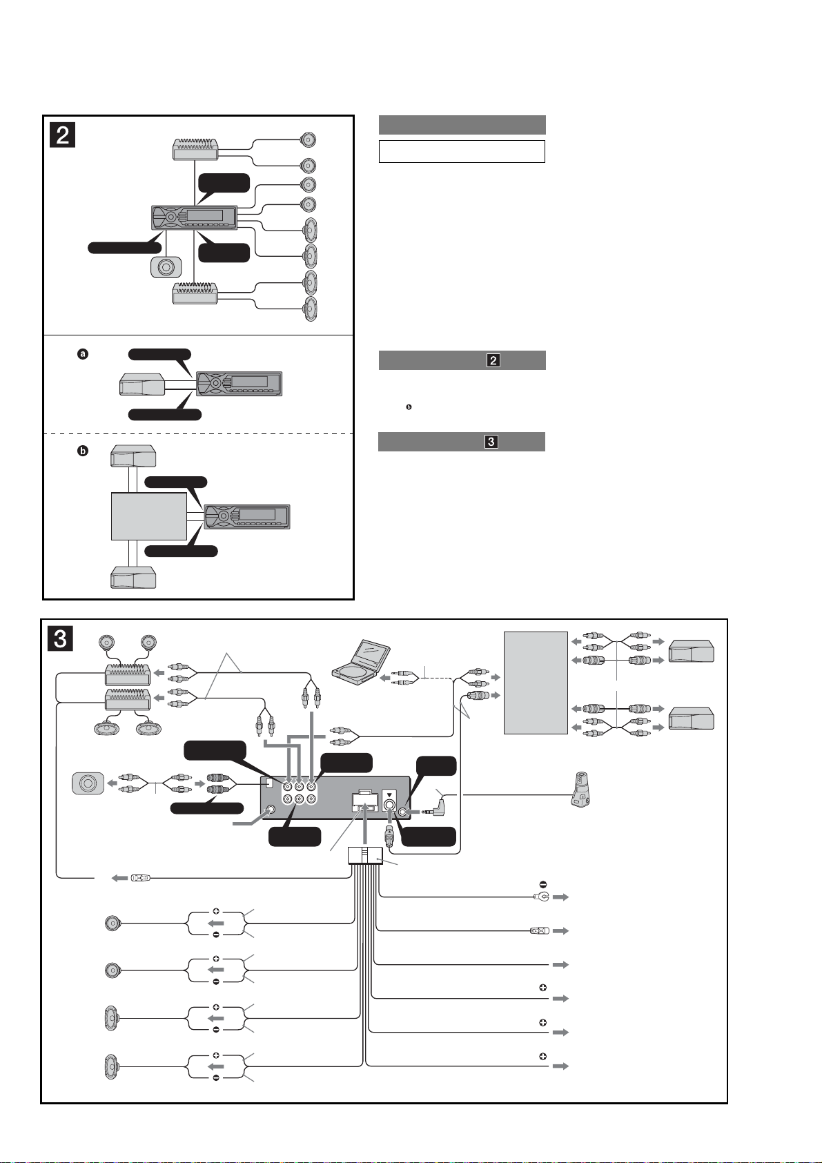
(US, Canadian, E)
A
SUB OUT (MONO
B
Source selector*
)
BUS AUDIO IN
BUS CONTROL IN
BUS AUDIO IN
XA-C40
BUS CONTROL IN
AUDIO OUT
FRONT
AUDIO OUT
REAR
not supplied
*
Cautions
Be sure to install this unit in the dashboard of the car
as the rear side of the unit becomes hot during use.
• This unit is designed for negative ground 12 V DC
operation only.
• Do not get the leads under a screw, or caught in moving
parts (e.g. seat railing).
• Before making connections, turn the car ignition off to
avoid short circuits.
•
Connect the yellow and red power input leads only
after all other leads have been connected.
• Run all ground leads to a common ground
point.
• Be sure to in su late any loose un con nect ed leads with
electrical tape for safety.
• Do not cover the ventilation slots or heat sinks of the
unit.
• The use of optical instruments with this product will
increase eye hazard.
Notes on the power supply lead (yellow)
• When connecting this unit in combination with other
stereo components, the connected car circuit’s rating
must be higher than the sum of each component’s fuse.
• When no car circuits are rated high enough, connect
the unit directly to the battery.
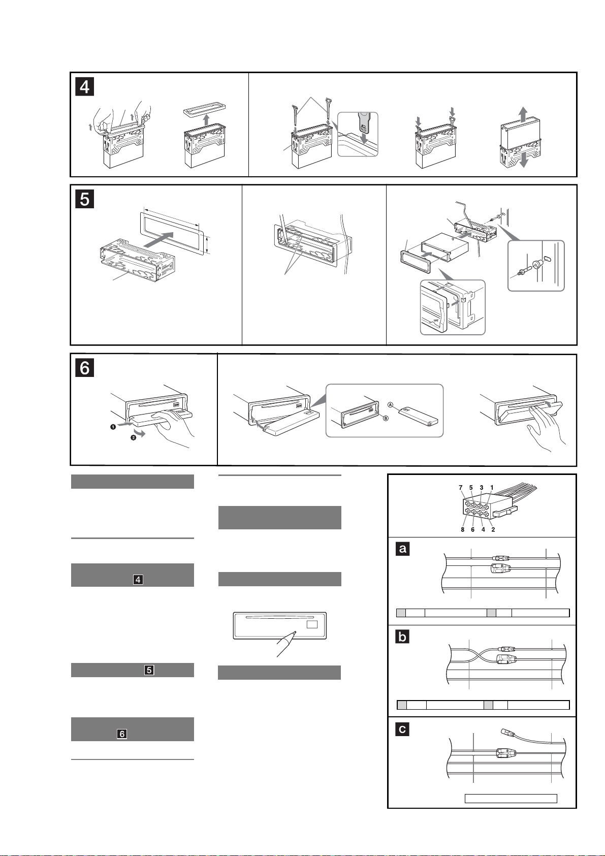
Connection example
Notes
(2-A)
Be sure to connect the ground lead before connecting the
amplifi er.
The alarm will only sound if the built-in amplifi er is used.
Tip
(2-B- )
For connecting two or more CD/MD changers, the source
selector XA-C40 (not supplied) is necessary.
Connection diagram
1 To a metal surface of the car
First connect the black ground lead, then connect the
orange/white striped, yellow, and red power input leads.
2 To the power antenna control lead or power
supply lead of antenna booster amplifler
Notes
•
It is not necessary to connect this lead if there is no power
antenna or antenna booster, or with a manually-operated
telescopic antenna.
•
When your car has a built-in FM/AM antenna in the rear/
side glass, see “Notes on the control and power supply
leads.”
3 To AMP REMOTE IN of an optional power
amplifler
This connection is only for amplifi ers. Connecting any other
system may damage the unit.
4 To the interface cable of a car telephone
5 To a car’s illumination signal
Be sure to connect the black ground lead to a metal surface
of the car fi rst.
6 To the +12 V power terminal which is
energized in the accessory position of the
ignition key switch
Notes
•
If there is no accessory position, connect to the +12 V
power (battery) terminal which is energized at all times.
Be sure to connect the black ground lead to a metal
surface of the car fi rst.
•
When your car has a built-in FM/AM antenna in the rear/
side glass, see “Notes on the control and power supply
leads.”
7 To the +12 V power terminal which is
energized at all times
Be sure to connect the black ground lead to a metal surface
of the car fi rst.
Notes on the control and power supply leads
•
The power antenna control lead (blue) supplies +12 V DC
when you turn on the tuner.
•
When your car has built-in FM/AM antenna in the rear/side
glass, connect the power antenna control lead (blue) or the
accessory power input lead (red) to the power terminal of the
existing antenna booster. For details, consult your dealer.
•
A power antenna without a relay box cannot be used with this
unit.
Memory hold connection
When the yellow power input lead is connected, power will
always be supplied to the memory circuit even when the ignition
switch is turned off.
Notes on speaker connection
•
Before connecting the speakers, turn the unit off.
•
Use speakers with an impedance of 4 to 8 ohms, and with
adequate power handling capacities to avoid its damage.
•
Do not connect the speaker terminals to the car chassis, or
connect the terminals of the right speakers with those of the
left speaker.
•
Do not connect the ground lead of this unit to the negative (−)
terminal of the speaker.
•
Do not attempt to connect the speakers in parallel.
•
Connect only passive speakers. Connecting active speakers
(with built-in amplifi ers) to the speaker terminals may damage
the unit.
•
To avoid a malfunction, do not use the built-in speaker leads
installed in your car if the unit shares a common negative (
lead for the right and left speakers.
•
Do not connect the unit’s speaker leads to each other.
Note on connection
If speaker and amplifi er are not connected correctly, “Failure”
appears in the display. In this case, make sure the speaker and
amplifi er are connected correctly.
−
)
Left
Right
Left
Right
3
BUS AUDIO IN
1
*
SUB OUT (MONO
from car antenna
AMP REM
Max. supply current 0.3 A
1
*
/AUX IN
*
Blue/white striped
2
)
AUDIO
BUS
OUT
AUDIO
REAR
IN
AUDIO OUT
REAR
Fuse (10 A)
White
White/black striped
Gray
Gray/black striped
Green
Green/black striped
Purple
Purple/black striped
AUDIO
FRONT
L
R
OUT
3
*
AUDIO OUT
FRONT
4
*
REMOTE
IN
6
*
BUS
CONTROL IN
2
Black
Blue
Light blue
Orange/white striped
Red
Yellow
Source selector
(not supplied)
5
*
ANT REM
Max. supply current 0.1 A
ATT
ILLUMINATION
XA-C40
Supplied with the CD/MD changer
1
2
4
1
*
RCA pin cord (not supplied)
2
*
Be sure to match the color-coded
5
6
7
cord for audio to the appropriate
jacks from the unit. If you connect
an optional CD/MD changer, you
cannot use AUX IN terminal.
3
*
Auxiliary optional equipment
such as portable DVD player (not
supplied)
4
*
Supplied with the auxiliary
equipment
5
*
Supplied with XA-C40
6
*
Insert with the cord upwards.
12
MEX-BT5000
12
4
c
12 3
182 mm
53 mm
Claws
max. size
5 × 8 mm
7
/32 × 11/32 in)
(
1
A
5
TOYOTA
3
Face the hook inwards.
c
1
Dashboard
4
B
NISSAN
5
max. size
5 × 8 mm
7
(
/32 × 11/32 in)
c
1
to dashboard/center console
Bracket
Bracket
Existing parts supplied with your car
5
max. size
5 × 8 mm
7
/32 × 11/32 in)
(
AB
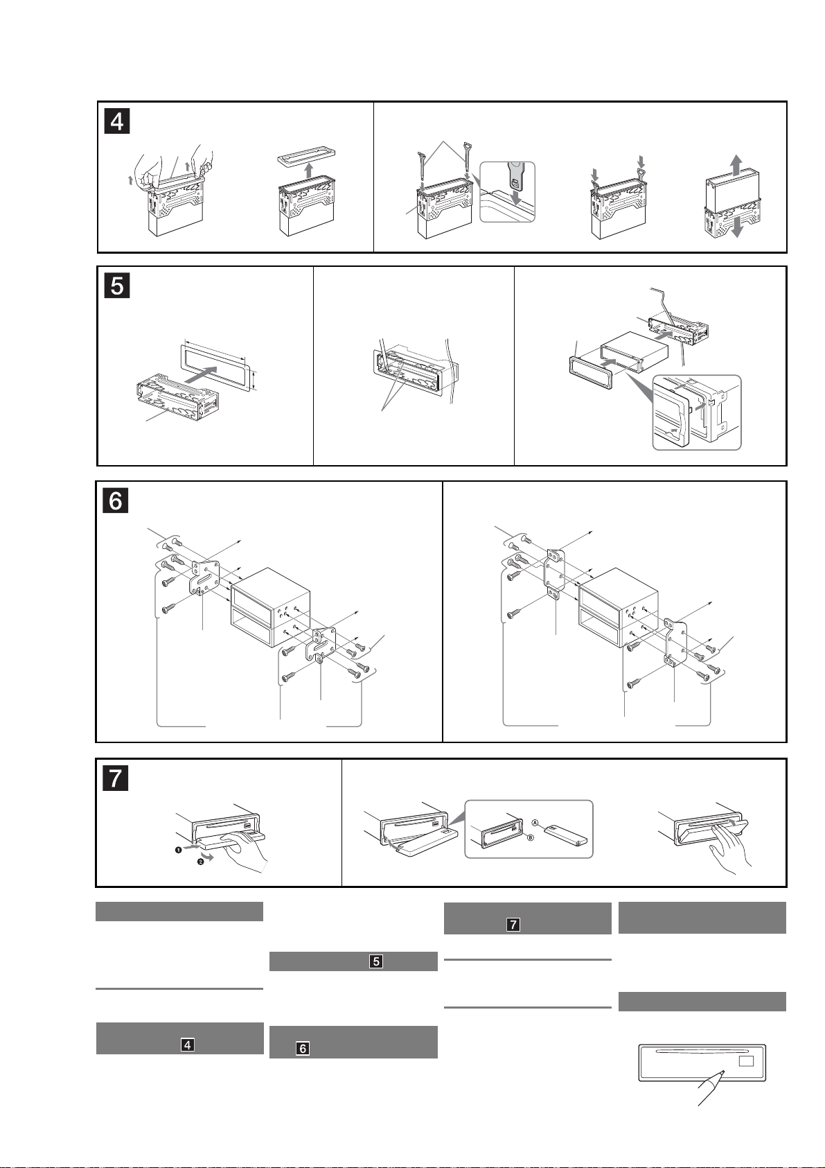
Precautions
Choose the installation location carefully so that the
unit will not interfere with normal driving operations.
Avoid installing the unit in areas subject to dust, dirt,
excessive vibration, or high temperatures, such as in
direct sunlight or near heater ducts.
Use only the supplied mounting hardware for a safe
and secure installation.
Mounting angle adjustment
Adjust the mounting angle to less than 45°.
Removing the protection collar
and the bracket
Before installing the unit, remove the protection
collar 4 and the bracket 1 from the unit.
1 Remove the protection collar 4.
Pinch both edges of the protection collar 4, then
pull it out.
2 Remove the bracket 1.
1 Insert both release keys 3 together between
the unit and the bracket
2 Pull down the bracket
to separate.
1
until they click.
1
, then pull up the unit
Mounting example
Installation in the dashboard
Notes
Bend these claws outward for a tight fi t, if necessary
Make sure that the 4 catches on the protection collar
properly engaged in the slots of the unit
(5-3)
(5-2)
4
are
.
Mounting the unit in a Japanese
car
You may not be able to install this unit in some makes of
Japanese cars. In such a case, consult your Sony dealer.
Note
To prevent malfunction, install only with the supplied screws
5
How to detach and attach the
front panel
Before installing the unit, detach the front panel.
7-A To detach
Before detaching the front panel, be sure to press (OFF).
Press (OPEN), then slide the front panel to the right, and
gently pull out the left end of the front panel.
.
7-B To attach
Place the hole A of the front panel onto the spindle B
on the unit, then lightly push the left side in.
.
Bracket
Existing parts supplied with your car
c
After turning the ignition off, be sure to press
and hold (OFF) on the unit until the display
disappears.
Otherwise, the display does not turn off and this causes
battery drain.
When the installation and connections are completed,
be sure to press the RESET button with a ball-point pen,
etc., after detaching the front panel.
to dashboard/center console
5
max. size
5 × 8 mm
7
/32 × 11/32 in)
(
Bracket
Warning if your car’s ignition
has no ACC position
RESET button
13
MEX-BT5000
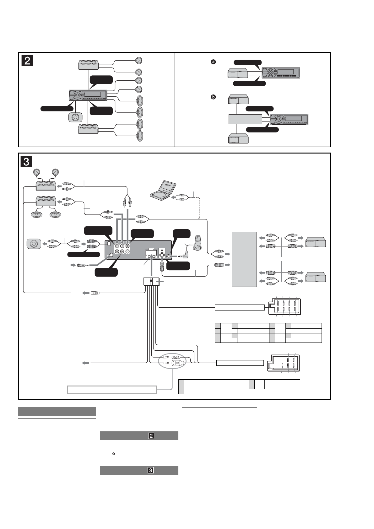
(AEP, UK)
A
S
UB OUT (MONO
1
from car aerial
*
Max. supply current 0.3 A
)
2
*
SUB OUT (MONO)
A
2
*
*
BUS AUDIO IN/
AUX IN
2
AMP REM
AUDIO OUT
FRONT
AUDIO OUT
REAR
2
3
*
AUDIO OUT
REAR
AUDIO
AUDIO
BUS
OUT
OUT
AUDIO
REAR
FRONT
IN
Blue/white striped
AUDIO OUT
FRONT
L
R
Fuse (10 A)
*
4
REMOTE
BUS
CONTROL IN
3
B
BUS AUDIO IN
BUS CONTROL IN
BUS AUDIO IN
Source selector*
XA-C40
BUS CONTROL IN
*
not supplied
1
Note for the aerial connecting
*
If your car aerial is an ISO (International
Organisation for Standardisation) type, use the
supplied adaptor
the car aerial to the supplied adaptor, then
connect it to the aerial jack of the master unit.
2
*
RCA pin cord (not supplied)
3
*
Be sure to match the colour-coded cord for
audio to the appropriate jacks from the unit. If
you connect an optional CD/MD changer, you
cannot use AUX IN terminal.
5
*
7
IN
6
*
*
*
Source selector
(not supplied)
7
XA-C40
4
*
Auxiliary equipment such as portable DVD
player (not supplied)
5
*
Supplied with the auxiliary equipment
6
*
Insert with the cord upwards
7
*
Supplied with XA-C40
Supplied with the CD/MD changer
2
to connect it. First connect
13 57
ATT
B
See “Power connection diagram” on the reverse side for details.
Cautions
Be sure to install this unit in the dashboard of the car as
the rear side of the unit becomes hot during use.
• This unit is designed for negative earth 12 V DC operation
only.
• Do not get the leads under a screw, or caught in moving
parts (e.g. seat railing).
• Before making connections, turn the car ignition off to
avoid short circuits.
• Connect the power connecting lead 3 to the unit and
speakers before connecting it to the auxiliary power
connector.
• Run all earth leads to a common earth point.
• Be sure to insulate any loose unconnected leads with
electrical tape for safety.
• Do not cover the ventilation slots or heat sinks of the unit.
Light blue
Notes on the power supply lead (yellow)
• When connecting this unit in combination with other
stereo components, the connected car circuit’s rating must
be higher than the sum of each component’s fuse.
• When no car circuits are rated high enough, connect the
unit directly to the battery.
Connection example
Notes
(2-A)
•
Be sure to connect the earth lead before connecting the amplifi er.
•
The alarm will only sound if the built-in amplifi er is used.
Tip
(2-B-
)
For connecting two or more CD/MD changers, the source selector
XA-C40 (not supplied) is necessary.
Connection diagram
A To AMP REMOTE IN of an optional power
amplifier
This connection is only for amplifi ers. Connecting any other
system may damage the unit.
B To the interface cable of a car telephone
from the car’s speaker connector
Purple
Grey
Speaker, Rear, Right
+
–
Speaker, Rear, Right
Speaker, Front, Right
+
Speaker, Front, Right
–
1
2
3
4
Negative polarity positions 2, 4, 6, and 8 have striped leads.
from the car’s power connector
Yellow continuous power supply
4
Blue power aerial control
5
Orange/White switched illumination power supply
6
Warning
If you have a power aerial without a relay box, connecting
this unit with the supplied power connecting lead 3 may
damage the aerial.
Notes on the control power and suppy leads
•
The power aerial control lead (blue) supplies +12 V DC when
you turn on the tuner, or when you activate the AF (Alternative
Frequency) or TA (Traffi c Announcement) function.
•
When your car has built-in FM/MW/LW aerial in the rear/side
glass, connect the power aerial control lead (blue) or the
accessory power input lead (red) to the power terminal of the
existing aerial booster. For details, consult your dealer.
•
A power aerial without a relay box cannot be used with this unit.
Memory hold connection
When the yellow power input lead is connected, power will always
be supplied to the memory circuit even when the ignition switch is
turned off.
24 68
White
Green
Speaker, Front, Left
+
–
Speaker, Front, Left
Speaker, Rear, Left
+
Speaker, Rear, Left
5
6
7
8–
57
6
48
Red switched power supply
7
Black earth
8
Positions 1, 2 and 3 do not have pins.
Notes on speaker connection
•
Before connecting the speakers, turn the unit off.
•
Use speakers with an impedance of 4 to 8 ohms, and with
adequate power handling capacities to avoid its damage.
•
Do not connect the speaker terminals to the car chassis,
or connect the terminals of the right speakers with those
of the left speaker.
•
Do not connect the earth lead of this unit to the negative (–)
terminal of the speaker.
•
Do not attempt to connect the speakers in parallel.
•
Connect only passive speakers. Connecting active
speakers (with built-in amplifi ers) to the speaker terminals
may damage the unit.
•
To avoid a malfunction, do not use the built-in speaker leads
installed in your car if the unit shares a common negative (–)
lead for the right and left speakers.
•
Do not connect the unit’s speaker leads to each other.
Note on connection
If speaker and amplifi er are not connected correctly, “Failure”
appears in the display. In this case, make sure the speaker
and amplifi er are connected correctly.
14
MEX-BT5000
1
5
cc
123
182 mm
53 mm
1
A
B
2
1
Claws
4
Face the hook inwards.
c
Dashboard
1
Fire wall
5
6
7
Precautions
• Choose the installation location carefully so that the
unit will not interfere with normal driving operations.
• Avoid installing the unit in areas subject to dust, dirt,
excessive vibration, or high temperature, such as in
direct sunlight or near heater ducts.
• Use only the supplied mounting hardware for a safe
and secure installation.
Mounting angle adjustment
Adjust the mounting angle to less than 45°.
Removing the protection collar
and the bracket
Before installing the unit, remove the protection
collar 5 and the bracket 1 from the unit.
1
Remove the protection collar 5.
Pinch both edges of the protection collar 5, then
pull it out.
2
Remove the bracket 1.
1 Insert both release keys 4 together between
the unit and the bracket 1 until they click.
2 Pull down the bracket 1, then pull up the unit
to separate.
Mounting example
Installation in the dashboard
Notes
•
Bend these claws outward for a tight fi t, if necessary
•
Make sure that the 4 catches on the protection collar 5 are
properly engaged in the slots of the unit
(5-3)
(5-2)
.
.
How to detach and attach the
front panel
Before installing the unit, detach the front panel.
6-A To detach
Before detaching the front panel, be sure to press (OFF).
Press (OPEN), then slide the front panel to the right
side, and pull out the left side.
6-B To attach
Place the hole A in the front panel onto the spindle B
on the unit, as illustrated, then push the left side in.
Warning if your carís ignition
has no ACC position
After turning the ignition off, be sure to press
and hold (OFF) on the unit until the display
disappears.
Otherwise, the display does not turn off and this causes
battery drain.
RESET button
When the installation and connections are completed, be
sure to press the RESET button with a ballpoint pen, etc.,
after detaching the front panel.
Power connection diagram
Auxiliary power connector may vary depending on the
car. Check your carís auxiliary power connector diagram
to make sure the connections match correctly. There are
three basic types (illustrated below). You may need to
switch the positions of the red and yellow leads in the car
stereoís power connecting lead.
After matching the connections and switched power
supply leads correctly, connect the unit to the carís
power supply. If you have any questions and problems
connecting your unit that are not covered in this manual,
please consult the car dealer.
c
Auxiliary power
connector
Yellow Yellow
Yellow continuous power supply7Red switched power supply
4
Yellow Yellow
Yellow switched power supply7Red continuous power supply
4
Yellow Yellow
the car without ACC position
RedRed
RedRed
RedRed
15
MEX-BT5000
• This set can be disassembled in the order shown below.
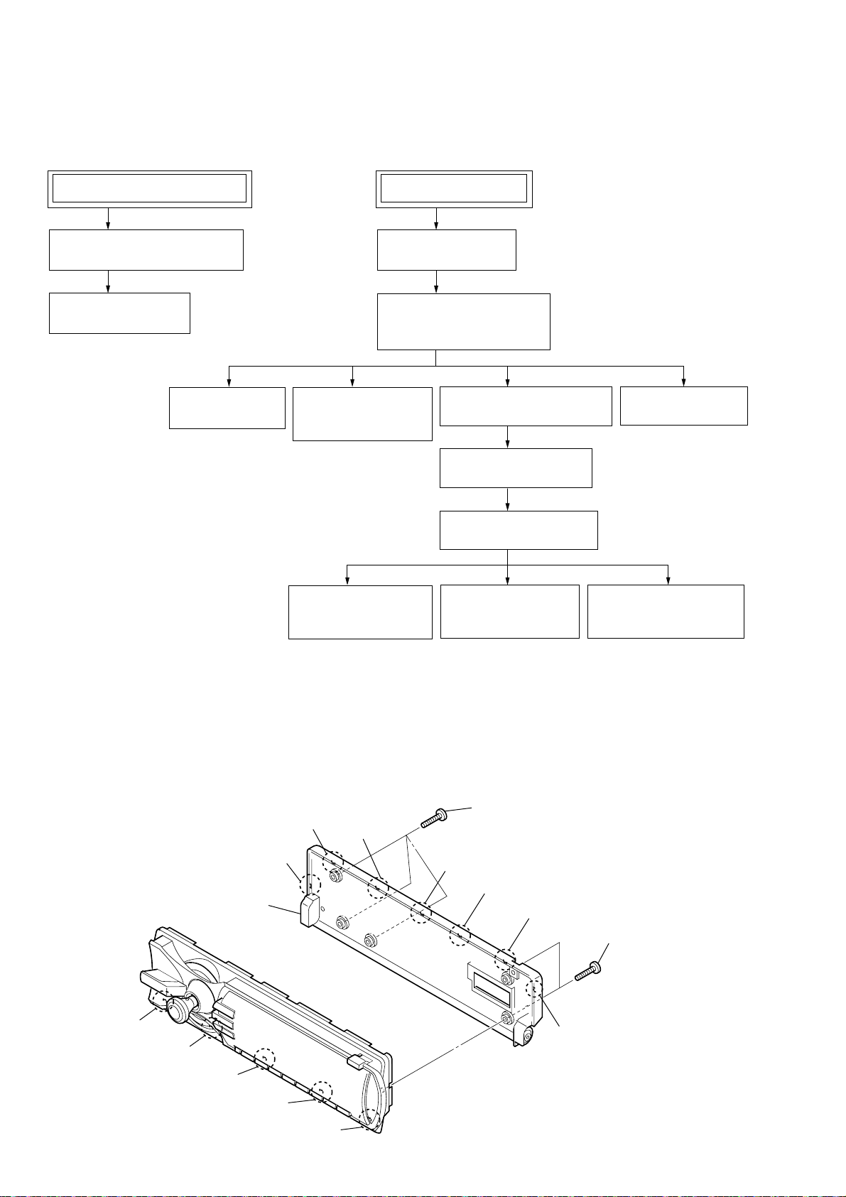
3-1. DISASSEMBLY FLOW
SECTION 3
DISASSEMBLY
SET (FRONT PANEL BLOCK)
3-2. FRONT BACK PANEL ASSY
(Page 16)
3-3. KEY BOARD
(Page 17)
3-6. MAIN BOARD
(Page 18)
SET (MAIN BLOCK)
3-4. SUB PANEL ASSY
(Page 17)
3-5. CD MECHANISM BLOCK
(MG-611WA-186//Q)
(Page 18)
3-7. ANTENNA BOARD,
IT BOARD
(Page 19)
3-11.OPTICAL PICK-UP
(KSS1000E)
(Page 21)
3-8. CHASSIS (T) SUB ASSY
(Page 19)
3-9. ROLLER ARM ASSY
(Page 20)
3-10.CHASSIS (OP) ASSY
(Page 20)
3-12.SL MOTOR ASSY
(SLED) (M902)
(Page 21)
3-14.SERVO BOARD
(Page 22)
3-13.LE MOTOR ASSY (B)
(LOADING) (M903)
(Page 22)
Note: Follow the disassembly procedure in the numerical order given.
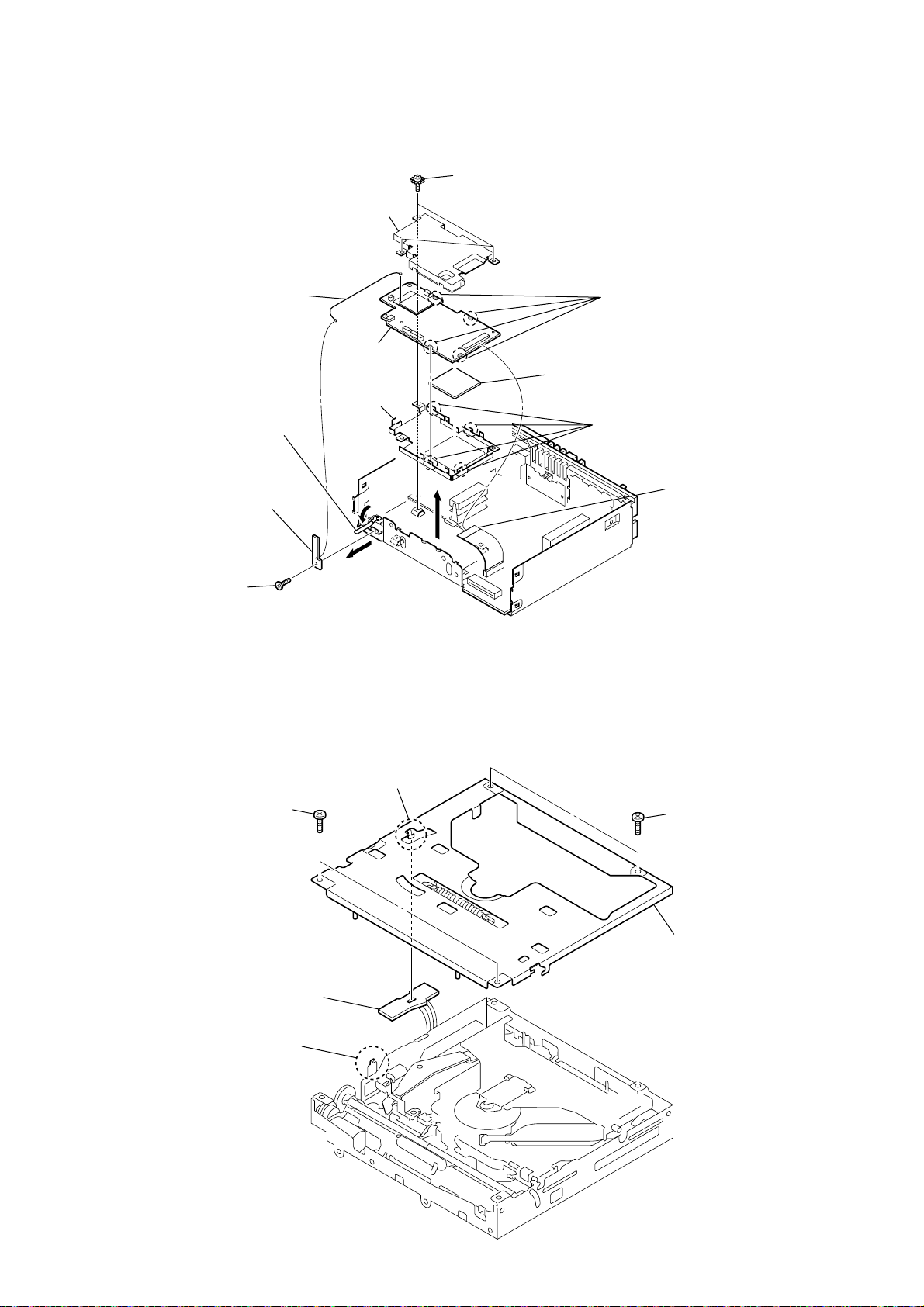
3-2. FRONT BACK PANEL ASSY
2
claw
qd
claw
qf
qs
claw
front back
qa
claw
panel assy
q;
claw
9
claw
3
claw
4
1
claw
5
three
screws
(B P-TITE M2)
claw
6
claw
7
claw
1
two
screws
(B P-TITE M2)
16
8
claw
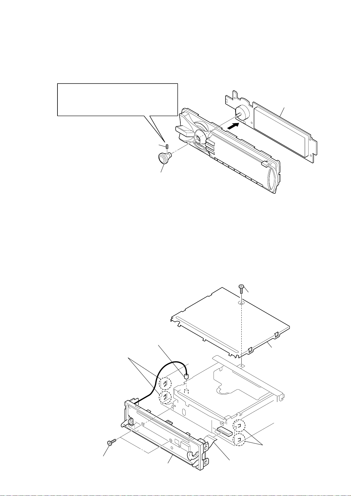
3-3. KEY BOARD
)
Note1:
Please use a hexagon head wrench of 0.89mm
when you remove hexagon socket set screw.
Note2:
Please tighten by the torque of 1.5k when you
install hexagon socket set screw.
1
hexagon socket set screw
2
knob assy (S)
MEX-BT5000
3
KEY board
3-4. SUB PANEL ASSY
6
two claws
3
connector
(CN500)
1
screw
(PTT2.6
2
×
6)
cover
4
two
screws
(PTT2.6
×
5
two claws
7
6)
8
sub panel assy
flexible flat cable (22 core
(CN602)
17
MEX-BT5000
)
)
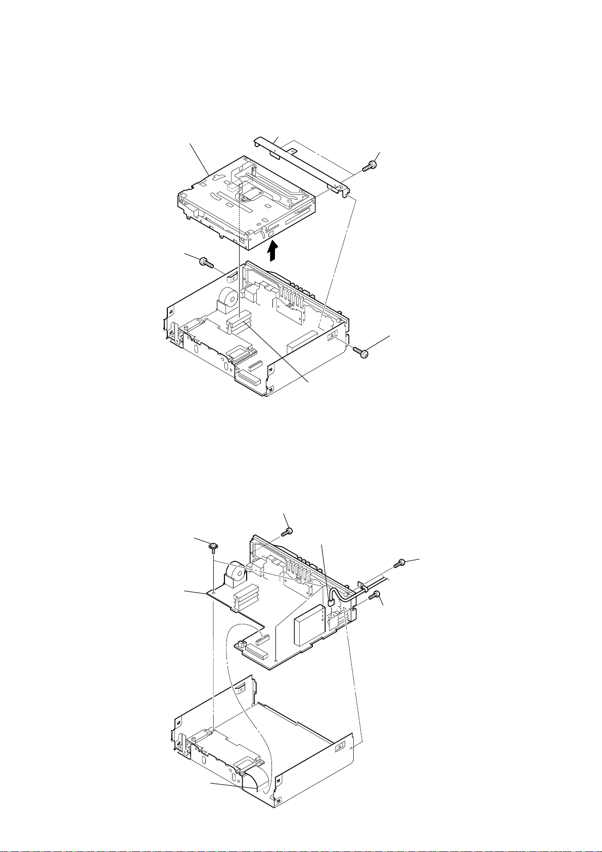
3-5. CD MECHANISM BLOCK (MG-611WA-186//Q)
7
CD mechanism block
(MG-611WA-186//Q)
6
bracket (CD)
5
two
screws
(PTT2.6
×
4)
3-6. MAIN BOARD
2
screw
(PTT2.6
×
3
6)
1
screw
(PTT2.6
×
6
4
connector
(CNP501)
4
screw
(PTT2.6
×
8)
5
three ground point
(PTT2.6
×
6)
6
MAIN board
1
flexible flat cable (40 core)
(CN503)
screws
3
RCA cord
(CN301)
connector
4
screw
(PTT2.6
2
×
screw
(PTT2.6
8)
×
8
18
3-7. ANTENNA BOARD, IT BOARD
y
9
shield plate (IT A)
4
coaxial cable
(ANTENNA board: CN1,
IT board)
qf
IT board
qs
shield plate
(IT B)
1
Open the clamp.
7
three ground point
(PTT2.6
×
6)
screws
qd
radiation sheet (SH)
q;
Remove the
qa
four claws
MEX-BT5000
four solders.
5
ANTENNA board
2
screw
(M1.7
×
3.5)
3-8. CHASSIS (T) SUB ASSY
1
two
screws
(P1.7
×
2.2)
3
2
8
claw
6
flexible flat cable (40 core)
(CN505)
1
two
screws
(P1.7
×
2.2)
3
SENSOR board
2
claw
4
chassis (T) sub ass
19
MEX-BT5000
)
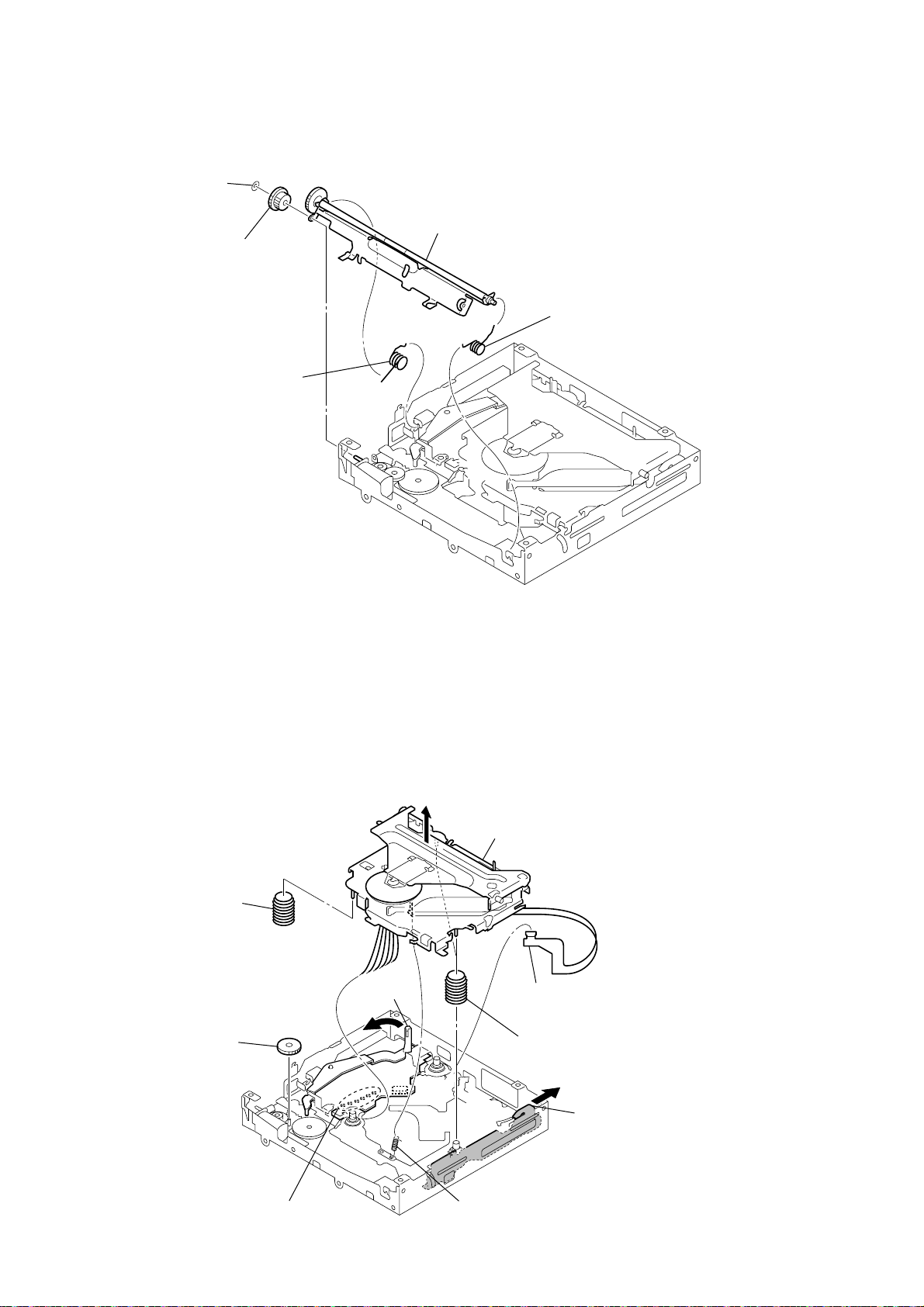
3-9. ROLLER ARM ASSY
3
washer
1
spring (RAL-B)
4
gear (RA1)
5
roller arm assy
2
spring (RAR-B)
3-10. CHASSIS (OP) ASSY
8
coil spring (damper)
4
gear (LE1)
lever (D)
5
7
9
chassis (OP) assy
1
optical pick-up flexible board (16 core
(CN1)
8
two coil springs (damper)
6
slider (R)
20
2
Remove the six solders.
3
tension spring (KF60)
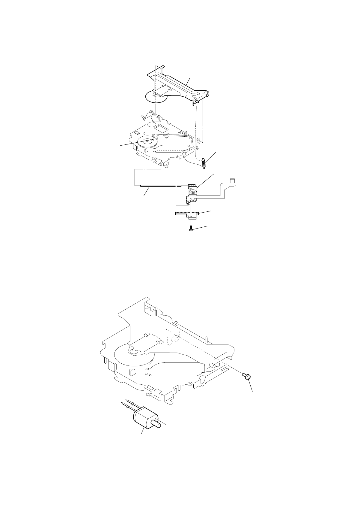
3-11. OPTICAL PICK-UP (KSS1000E)
)
5
claw
2
chucking arm sub assy
1
tension coil spring (CHKG
7
optical pick-up (KSS1000E)
MEX-BT5000
6
3-12. SL MOTOR ASSY (SLED) (M902)
main shaft
3
4
rack (SL)
screw
(B1.4
×
5)
2
SL motor assy (sled)
(M902)
1
screw
(P1.4
×
1.8)
21
MEX-BT5000
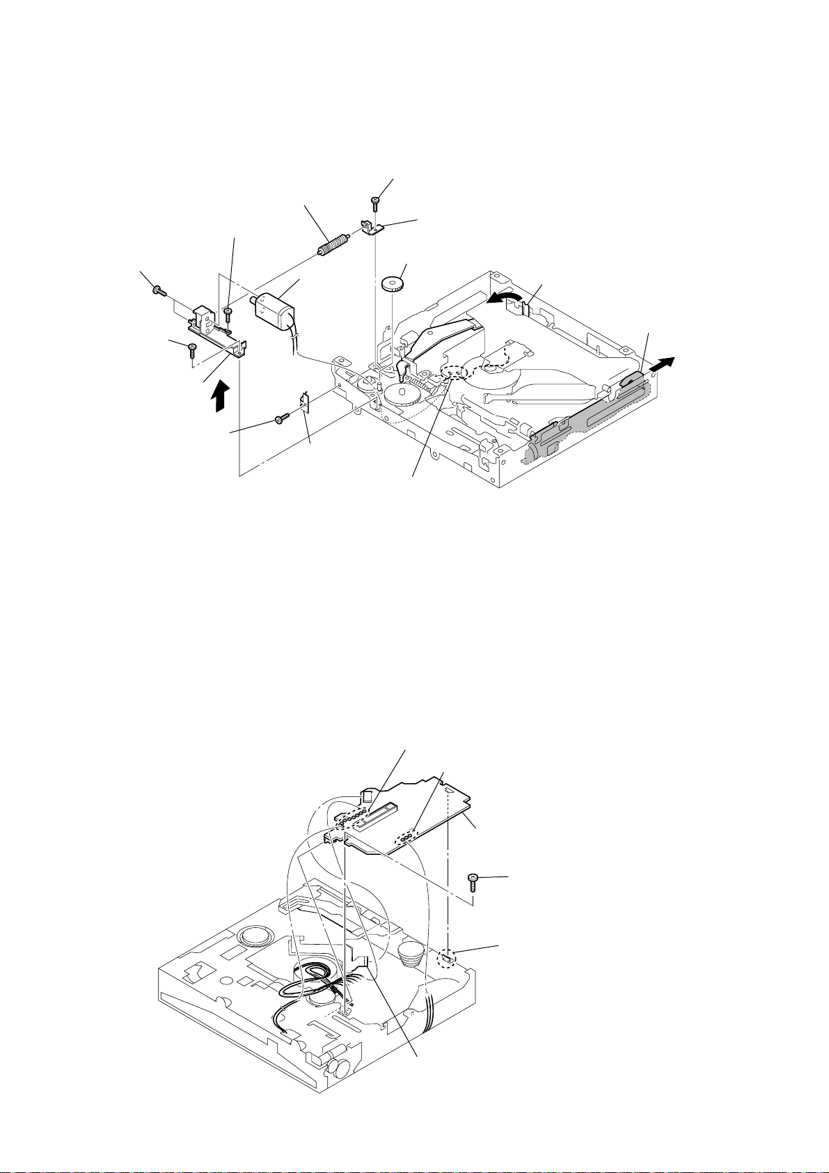
3-13. LE MOTOR ASSY (B) (LOADING) (M903)
9
gear (LE) assy
q;
screw
(M1.7
×
qd
two toothed lock
(M1.4)
qa
screw
(M1.7
×
bracket (LEM-N)
2.5)
5
screw
(P1.7
screws
×
2.2)
qs
2.5)
qf
6
LE motor
assy (B)
(loading)
(M903)
leaf spring (LE)
7
2
screw
(M1.7
×
2.5)
8
bearing (LEB-N)
gear (LE1)
lever (D)
3
slider (R)
4
3-14. SERVO BOARD
1
Remove the two solders.
1
Remove the eight solders.
2
Remove the three solders.
6
SERVO board
4
screw
22
5
claw
3
optical pick-up flexible board (16 core)
(CN1)
SECTION 4
TEST MODE
MEX-BT5000
SERVICE MODE
The version of each microcomputer is displayed. The firmware can
be updated.
1. Version Display
Procedure:
1. Power supply of the set is turned off.
2. Press the [4] t [5] t [6] ([6] is pressed for two seconds)
button of the set sequentially, and enter the service mode.
3. The version of each microcomputer confirmation screen is
displayed.
4. Press the [OFF] button of the set, and release the service mode.
2. The Version Up of the Firmware
To secure the connectivity with the new cellular phone etc. put on
the market after this machine is put on the market, the upgrade in
service is done.
Procedure:
1. The USB memory is prepared, and the firmware is downloaded
to the USB memory. (The USB memory is a thing to prepare
the one of about 64MB made of SONY POCKET BIT.)
2. Power supply of the set is turned off.
3. Press the [4] t [5] t [6] ([6] is pressed for two seconds)
button of the set sequentially, and enter the service mode.
4. Wait for 1 minute after executing step 3, the set is connected
with the USB memory with connected the USB cable (Part.
No. J-2502-103-1).
5. Wait for 1 minute (time untill access LED of USB memory
disappears) after executing step 4, push the joystick for two
seconds of the set, and the version up confirmation screen is
displayed.
6. Select “Y es” by using the UP/DOWN of joystick, and conf irm
the displayed version number, and push the joystick.
7. The version up is executed. When the version up ends, reset is
automatically done, and usual screen of power off state is
displayed.
DIAG MODE
Mode that memorizes reset frequency and operating time, etc. in
nonvolatile memory, and reads it.
Procedure:
1. Turn off the setting of the bluetooth signal, and po wer supply
is turned off.
2. Press the [4] t [5] t [4] ([4] is pressed for two seconds)
button of the set sequentially, and enter the DIAG mode.
3. Following information is displayed when operating it according
to Fig.1.
Reset frequency
Frequency to which [RESET] button is pressed and
frequency of POWER ON RESET when po wer supply is
turned on.
Software reset when releasing test mode is not counted.
Number of maximum counts: 254 times.
Reset frequency with watchdog timer
Reset frequency with watchdog timer.
Number of maximum counts: 254 times.
Number of connected slave units
The number of an external connection of the SONY BUS
slave unit is memorized by 3 histories or less.
The SONY BUS slave unit that becomes an object is CD
slave, MD slave, and undefined slave.
Connected number in test mode is off the subject.
Operating time
Time that the set is operating (Every hour) is counted.
Operating time in test mode is off the subject.
Time of maximum counts: 65534 hours.
CD error information
CD mechanism error information in the head unit is
memorized by 3 histories or less.
The memorized content is error information, a track kind,
and operating time (Every hour).
Error in test mode is off the subject.
Amplifier IC with built-in power supply error information
Information on the OFFSET/FAILURE error with
amplifier IC with built-in the power supply is memorized
by 3 histories or less.
The memorized content is error information and operating
time (Every hour).
OFFSET/FAILURE error in test mode is off the subject.
4. Press the [OFF] button of the set, and release the DIA G mode.
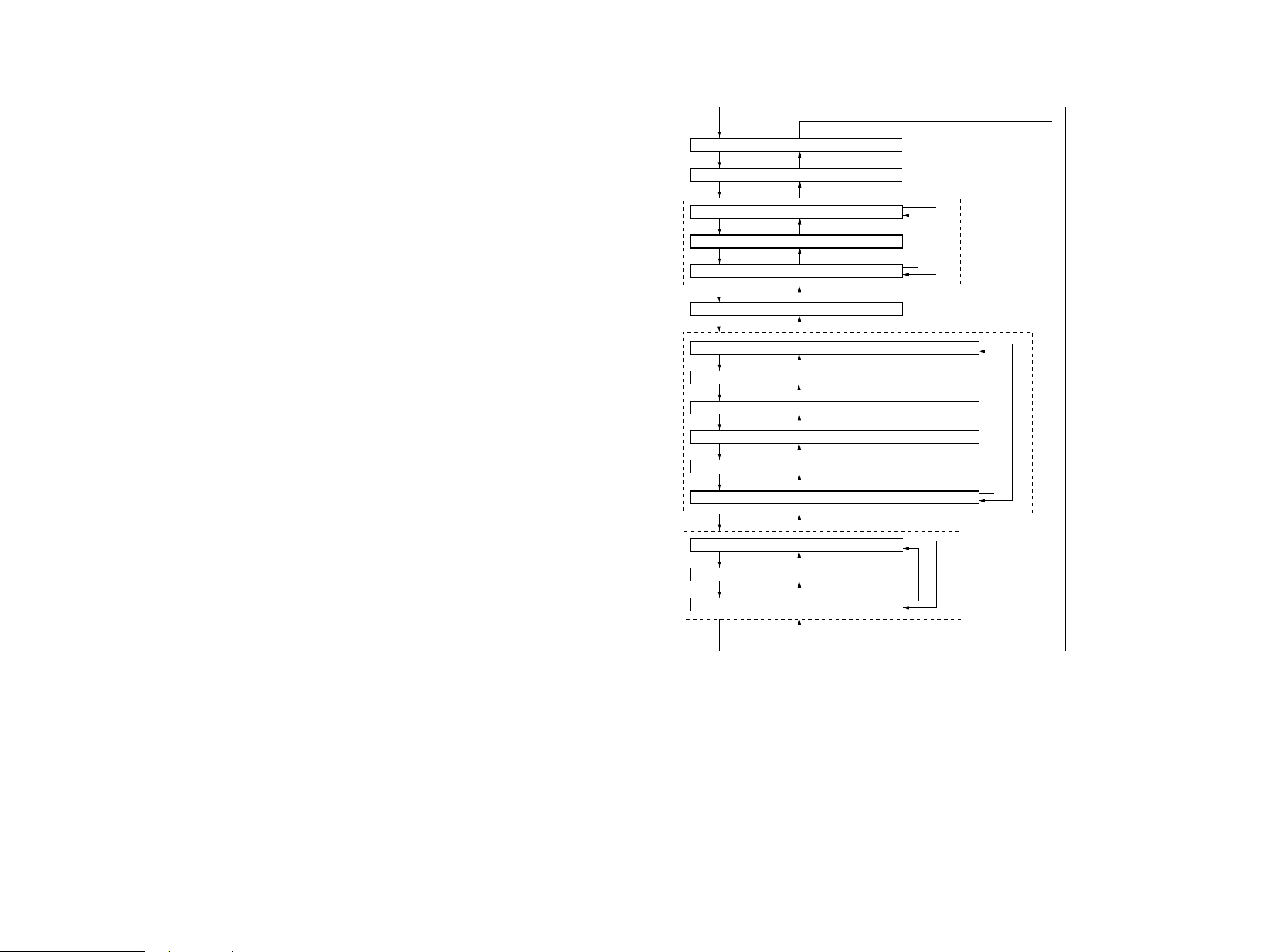
Fig.1 Method of operating DIAG mode
Joystick to right
01 Reset frequency
Joystick to right
02 Reset frequency with watchdog timer
Joystick to right
031 Number of connected slave units (History 1)
Joystick to up
032 Number of connected slave units (History 2)
Joystick to up
033 Number of connected slave units (History 3)
Joystick to right
04 Operating time
Joystick to right
051 CD error information (error content + error detailed) (History 1)
Joystick to up
052 CD error information (track kind + operating time) (History 1)
Joystick to up
053 CD error information (error content + error detailed) (History 2)
Joystick to up
054 CD error information (track kind + operating time) (History 2)
Joystick to up
055 CD error information (error content + error detailed) (History 3)
Joystick to up
056 CD error information (track kind + operating time) (History 3)
Joystick to right
061 OFFSET/FAILURE error (History 1)
Joystick to up
062 OFFSET/FAILURE error (History 2)
Joystick to up
063 OFFSET/FAILURE error (History 3)
Joystick to left
Joystick to left
Joystick to left
Joystick to down
Joystick to down
Joystick to left
Joystick to left
Joystick to down
Joystick to down
Joystick to down
Joystick to down
Joystick to down
Joystick to left
Joystick to down
Joystick to down
Joystick to up
Joystick to up
Joystick to down
Joystick to down
Joystick to up
Joystick to down
MEX-BT5000
Joystick to right
Joystick to left
2323
MEX-BT5000
SECTION 5
DIAGRAMS
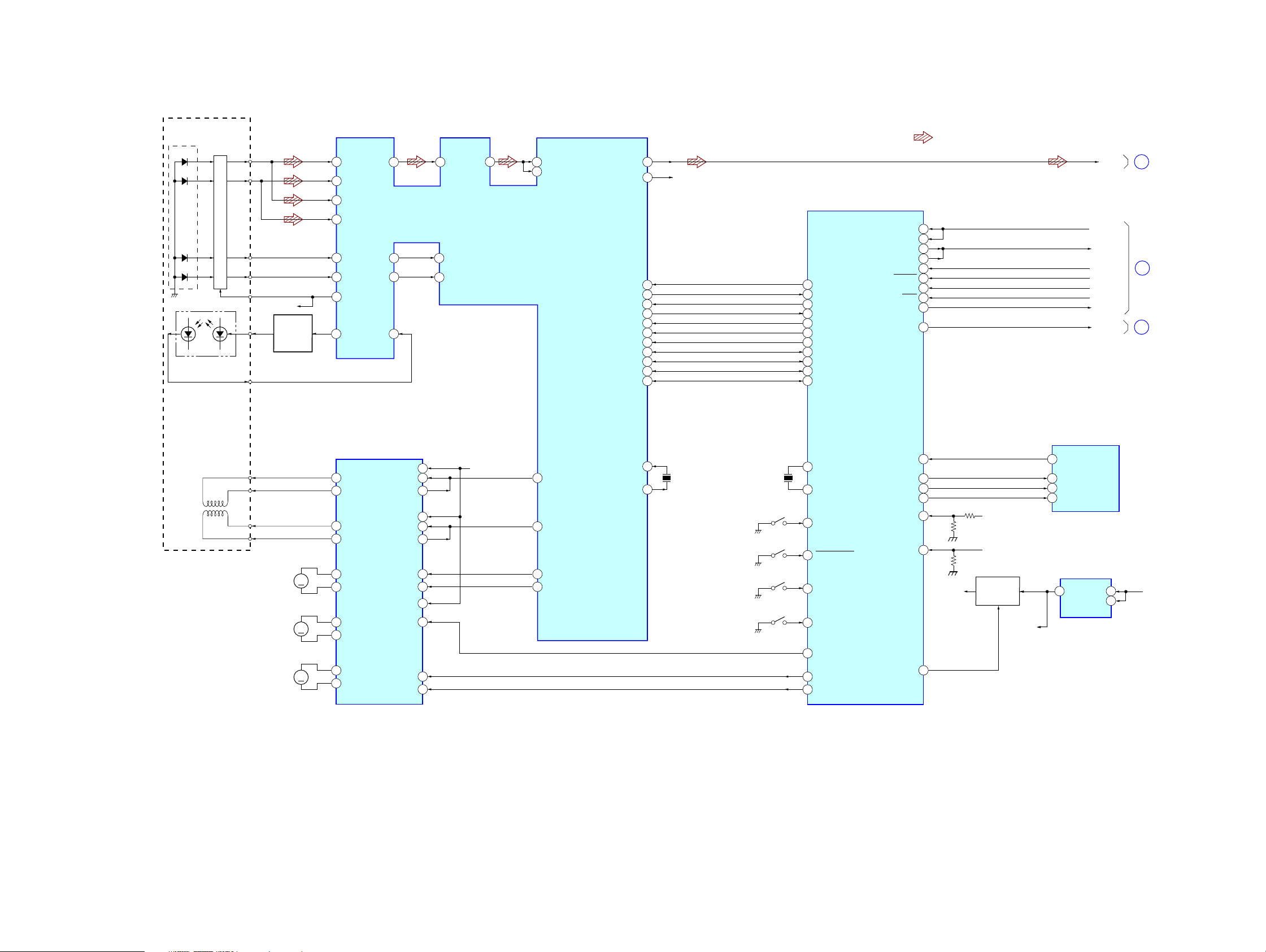
5-1. BLOCK DIAGRAM – CD SERVO Section –
DETECTOR
PD2
PD1
E
F
LASER DIODE
PD LD
PD2
PD1
I-V AMP
MON OUT
FPI2
96
FNI2
94
FPI1
97
FNI1
95
E
F
VC
VC
LD
AUTOMATIC
POWER
CONTROL
Q21
100
TNI
98
TPI
84
VRO
91
LDO
RFO
RFRP
MDI
89
3
TEI
6
92
• R-ch is omitted due to same as L-ch.
• Signal Path
: CD PLAY
83
RFEQO
88
AGCI
RF AMP,DIGITAL SERVO,
DIGITAL SIGNAL PROCESSOR
RFZI
2
TEZI
7
IC2
RFI
81
82
RFRPI
BUCK(CLK)
PIO3
PIO0
MSTBY
ZDET
/RST
/CCE
BUS3(SI)
BUS2(SO)
BUS1
BUS0
30
LO
27
RO
R-CH
UNISI
56
RXD
25
UNISO
57
TXD
26
UNICKI
58
BUS_ON
DEC_XMUTE
51
48
36
58
37
43
42
41
40
39
38
37
DEC_INT
30
DEC_SSTBY
27
CD_ZDET
15
CD_XRST
14
CD_XCCE
13
CD_BUCK
12
CD_BUS3
11
CD_BUS2
10
CD_BUS1
8
CD_BUS0
7
BU_IN
RSTX
LINKOFF
A_ATT
50
51
75
59
60
CD_L
UNI_SI
UNI_SO
UNI_CLK
BUS_ON
BU_IN
SYS_RST
LINK_OFF
A_ATT
A
B
C
(Page 26)
(Page 27)
(Page 26)
PICK-UP BLOCK
(KSS1000E)
2-AXIS DEVICE
(FOCUS)
(TRACKING)
OPTICAL
FCS+
FCS–
TRK+
TRK–
M902
(SLED)
M901
(SPINDLE)
M903
(LOADING)
CD
SYSTEM CONTROL
IC3
FOCUS/TRACKING COIL DRIVE,
SLED/SPINDLE/LOADING
MOTOR DRIVE
IC1
23
OPIN4+
16
VO4–
15
VO4+
18
VO3–
17
VO3+
14
M
M
M
VO1+
13
VO1–
12
VO2+
11
VO2–
10
VOL+
9
VOL–
OPIN4–
OPOUT4
OPIN3+
OPIN3–
OPOUT3
OPOUT1
OPOUT2
BIAS
MUTE
FWD
REV
27
26
25
24
23
22
4
7
20
21
1
28
LOAD
VC
FOO
9
TRO
10
FMO
12
DMO
13
XI
24
XO
X2
16.934MHz
SW1
(DOWN)
SW2
(SELF)
SW3
(DISC IN)
SW4
(LIMIT)
X1
12MHz
X1
81
X0
80
MEC_DSW
46
MEC_SELFSW
53
MEC_INSW
45
MEC_LIMIT
42
DRVON
6
MEC LOAD
43
MEC EJECT
44
XFLASH & EJECT_OK
MECON
CDON
ZMUTE
MECON_CHK
CDON_CHK
CDON_1500MV
61
63
64
66
67
68
CD +1.5V
1
1.5V_ON
CD +6V
CD +3.3V
+1.5V ON/OFF
SWITCH
Q2,3
M +1.5V
SYSTEM CONTROLLER
IC501 (1/4)
EJECT_OK
91
CDMON_IN
95
CDON_IN
94
CDMUTE_IN
93
+1.5V REG
IC6
VDD
VOUT
CE
15
3
BU +3.3V
MEX-BT5000
2424
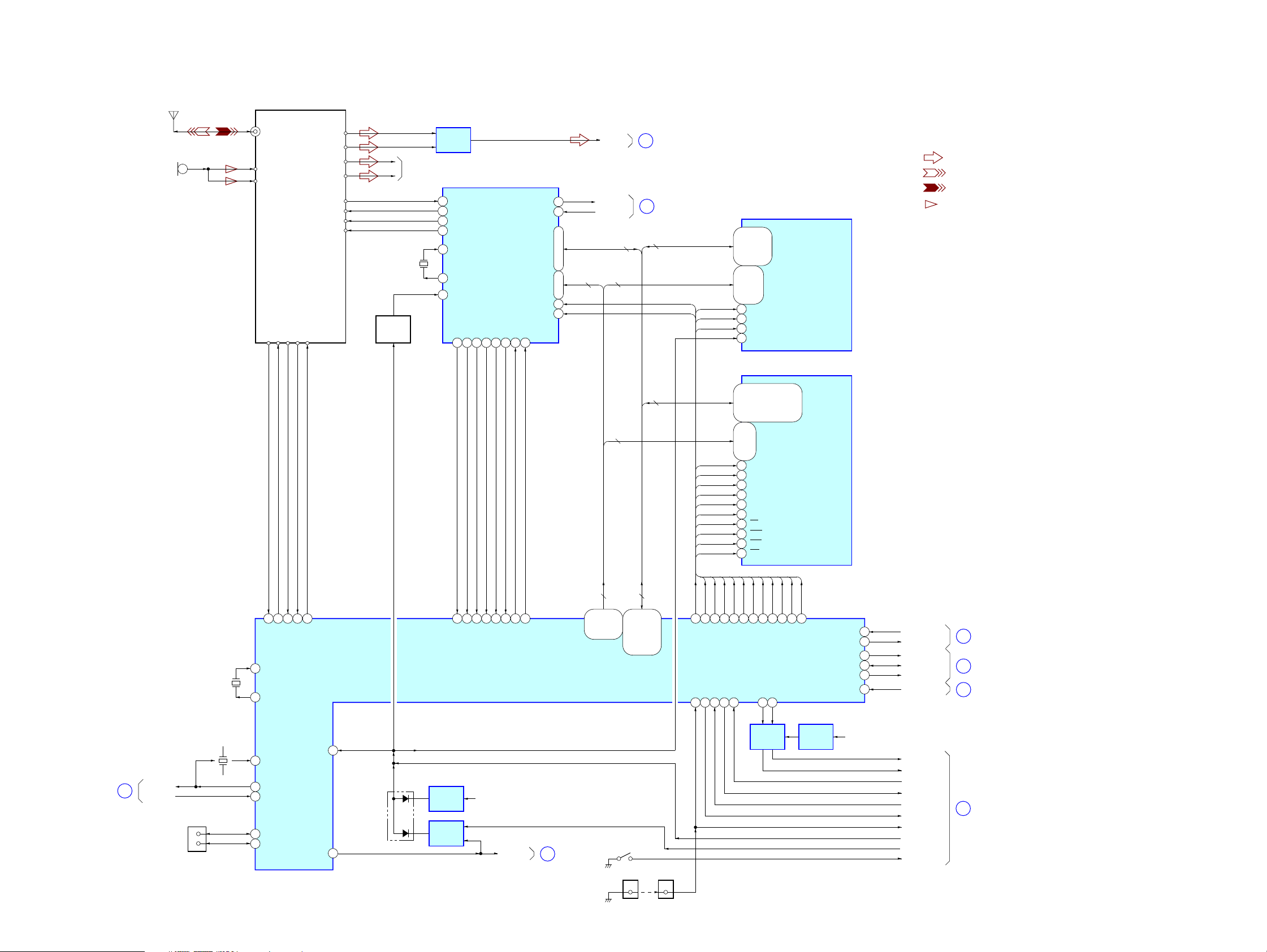
5-2. BLOCK DIAGRAM – BLUETOOTH Section –
BLUETOOTH MODULE
IC500
PATTERN
)(
ANTENNA
MIC500
4
5
A-IN_N_L
A-IN_P_L
SPI_MOSI
454344
SPI_MISO
SPI_CLK
SPI_CS
42
A-OUT_N_L
A-OUT_P_L
A-OUT_N_R
A-OUT_P_R
UART_TX
UART_RX
UART_RTS
UART_CTS
RESET
46
MEX-BT5000
9
10
7
8
41
40
39
38
X501
14.7456MHz
RESET
SWITCH
Q501
R-CH
LINE AMP
IC504
RXA
5
TXA
7
CTSA#
38
RTSA#
33
XTAL2
14
XTAL1
13
RST
36
30
INTA
DATA BUS INTERFACE
IC506
TXRDYA#
TXRDYB#10CSA#
RXRDYB#
INTB
RXRDYA#
6
18
29
31
D0 – D7
CSB#
1143
TXB
RXB
A0 – A2
IOW#
IOR#
8
4
44 – 48, 1 – 3
28 – 26
15
19
A0 – A2
BT_L
DISP_TX
DISP_RX
D0 – D7
A1 – A21
D
E
D0 – D15
(Page 26)
(Page 27)
DQMLL
RD
NOR_CS
RD
DQMLU
26 – 29,
32 – 35,
11 – 15,
1, 2, 5 – 8,
CE#
31
OE
37
WE
4
RST
10
DQ0 – DQ15
38, 39, 41,
42, 44 – 47
A0 – A20
17 – 25, 30
FLASH ROM
IC510
SD-RAM
IC512
• R-ch is omitted due to same as L-ch.
• Signal Path
: AUDIO
: BLUETOOTH OUT
: BLUETOOTH IN
: MIC
X503
12.5MHz
206
XTAL
179
EXTAL
180
185
204
205
186 110181
MISO
MOSI
SPICS
SPICLK
BT_RST
10
218
9
UART_INTB
UART_INTA
166
108
167
TXRDYB
TXRDYA
RXRDYA
RXRDYB
BLUETOOTH CONTROLLER
CSA
CSB
IC511
A2 – A14
A0 – A21
61 – 63, 65,
67 – 74, 76,
78 – 85, 87
A0 – A21
D0 – D31
D0 – D31
60 – 56, 54,
52 – 45, 43,
41 – 38, 36,
34 – 32, 30,
28 – 21
D0 – D31
DQMLL
DQMLU
DQMUL
DQMUU
SD_CLK
SD_CKE
SD_CS
SD_RAS
SD_CAS
RD/WR
DQMLL
DQMLU
98
97
DQMLL
DOOR_SW
119
138
DQMUL
99
DQMLU
DQMUL
MAS_PW
SH_PW
118
DQMUU
SD_CLK
101
19
DQMUU
MAS_TX
201
195
2, 4, 5, 7, 8,
10, 11, 13, 74,
60 – 66
22 – 27,
DQM0
16
DQM1
71
DQM2
28
DQM3
59
CLK
68
CKE
67
CS
20
RAS
19
CAS
18
WE
17
SD_CS
SD_CKE
128
107
SD_CKE
SD_CLK
MAS_RX
SD_CS
82, 83, 85, 31,
33, 34, 36, 37,
39, 40, 42, 45,
47, 48, 50, 51,
RD
RD/WR
SD_CAS
103
131
96
RD/WR
SD_CAS
SD_RAS
MAS_RST
MAS_FLSW
112
53, 54, 56
NOR_CS
105
RD
76, 77, 79, 80,
BS0, BS1, A0 – A10
SD_RAS
129
141
DQ0 – DQ31
EVOL_DATA
NOR_CS
DISP_FLSW
EVOL_CLK
DISP_PW
DISP_RST
ATT
233
111
142
140
114
120
EVOL_DATA
EVOL_CLK
DISP_FLS_W
DISP_IF
DISP_RST
ATT
H
J
K
(Page 26)
(Page 27)
(Page 26)
(Page 28)
MEX-BT5000
X502
48MHz
LCLK
219
USB1PWREN
USB_EN
F
USB_OCP
CN903
(USB)
D+
3
D–
2
126
USB1_OVR_CRNT
123
USB_D+
226
USB_D–
227
RESETP
SELF_PRCT
220
D500
113
VOLTAGE
DETECT
IC517
OR GATE
IC508
IT +3.3V
IT_POW
G
(Page 28)
S500
(NOSE DETECT)
CN70120CN902
10
BUS
SWITCH
IC516
VOLTAGE
DETECT
IC515
IT +3.3V
MAS_RST
MAS_FLS
MAS_RX
MAS_TX
MAS_POW
SH_POW
DOOR_SW
RESET
SH_RST
NOSE_SW
L
(Page 27)
2525
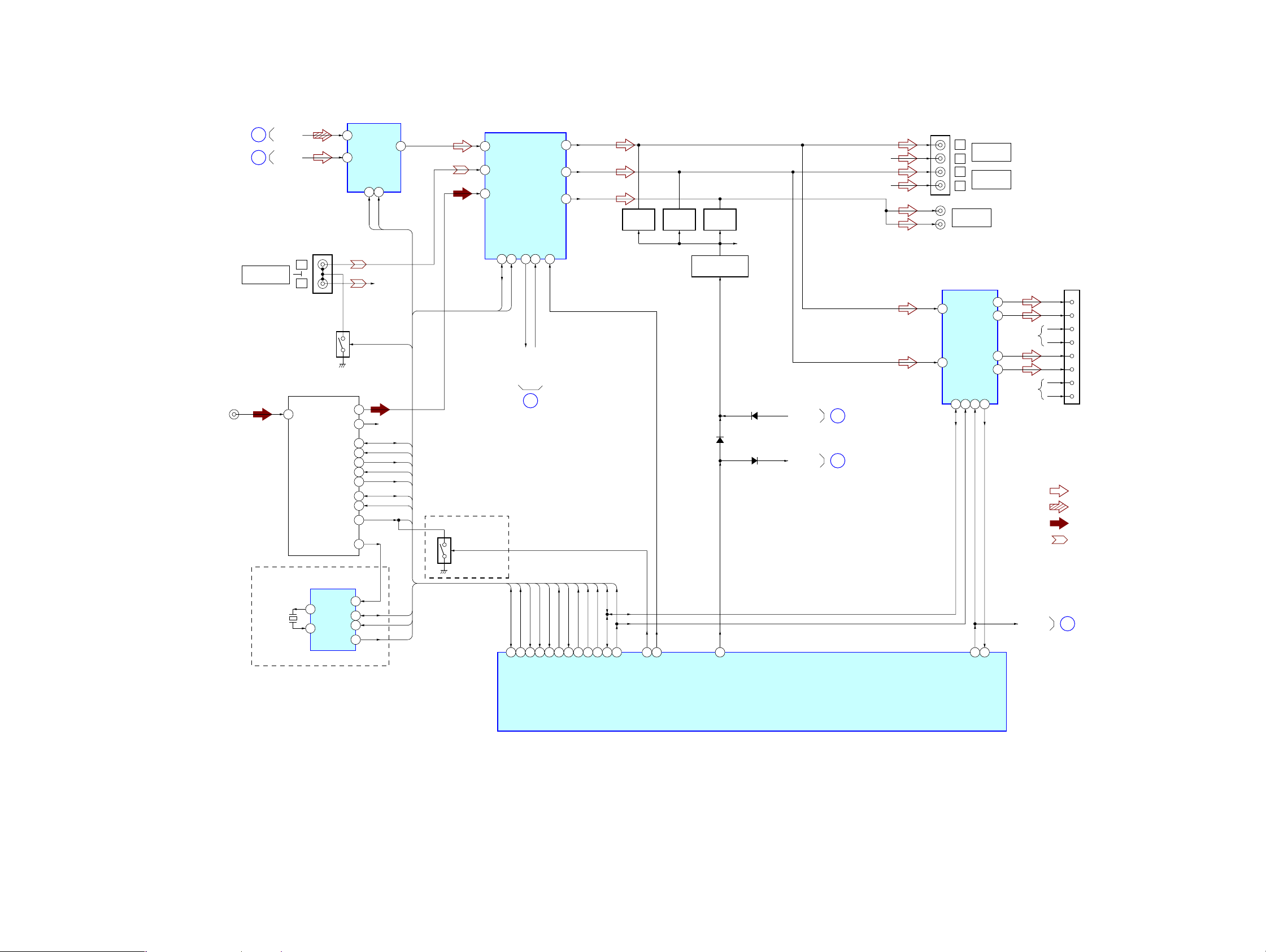
MEX-BT5000
5-3. BLOCK DIAGRAM – AUDIO Section –
(Page 24)
(Page 25)
J401
(ANTENNA IN)
A
D
BUS AUDIO IN/
AUX IN
CD_L
BT_L
L
R
GROUND
SWITCH
Q306
TUNER UNIT
1 ANT
MUTE-CONDITION
PJ301
(1/2)
TUX401
TUNER-LCH
TUNER-RCH
TU_SDA
TU_SCL
S_METER
TU_MUTE
E2P_SDA
E2P_SCL
QUALITY
AUDIO SELECT
IN1B
6
IN2B
7
4
3
14
13
6
7
8
17
16
5
RDS
9
IC302
CNT1
2
SW0
OUTB
11
CNT2
4
SW1
R-CH
BUS_AUX
R-CH
SDA
SCL
VSM
TU MUTE
MUTE CON
TRDA
TRCL
QUALITY
9
11
7
(AEP, UK)
NS DET DISCHARGE
SWITCH
Q401
ELECTRICAL VOLUME
IC301
22
SCL
OUTLF
OUTLR
SUB/LR
SAOUT26SAIN25MUTE
EVOL_CLK
EVOL_DATA
SE1L
DIFFL
SE2L
SDA23SCL
SDA
H
(Page 25)
PJ301
(2/2)
20
R-CH
19
R-CH
16
MUTING
Q301
21
MUTING
Q302
MUTING
Q305
MUTING CONTROL
Q307, 308
D305
R-CH
D304
D512
A_ATT
ATT
C
K
(Page 24)
(Page 25)
POWER AMP
FL
12
RL
11
L
AUDIO OUT
FRONT
R
L
AUDIO OUT
REAR
R
SUB OUT
(MONO)
IC201 (1/2)
LF+
LF–
LR+
LR–
SDA2SCL4STB22DIAG
25
CNP101 (1/2)
5
3
R-CH
9
7
R-CH
1
FL+
9
FL–
4
FR+
12
FR–
2
RL+
10
RL–
3
RR+
11
RR–
• R-ch is omitted due to same as L-ch.
• SIGNAL PATH
: AUDIO
: CD PLAY
: TUNER
: AUX IN
X401
8.664MHz
(AEP, UK)
RDS DECODER
IC401
10
XTO
XTI
9
MPX
SDA
SCL
INTN
SCL
SDA
SW0
BUS_AUX
MUTE CON
51
13
16
AUX_BUS
TUN ATTIN
SW1
32
31
14
I2CSIO
I2CCKO
SIGNAL_SW0
SIGNAL_SW1
17
NSMASK
2
VOL_ATT
STB
M
(Page 28)
6
19
ATT
SYSTEM CONTROLLER
IC501 (2/4)
24
DIAG
AMPSTB
16
12
11
15
SDA
SCL
DAVN
TRDA
22
TRCL
23
EESIO
DAVN
54
EECKO
QUALITY
36
DAVN
QUALITY
37
TU MUTE
10
VSM
TUNATT
VSM
MEX-BT5000
2626
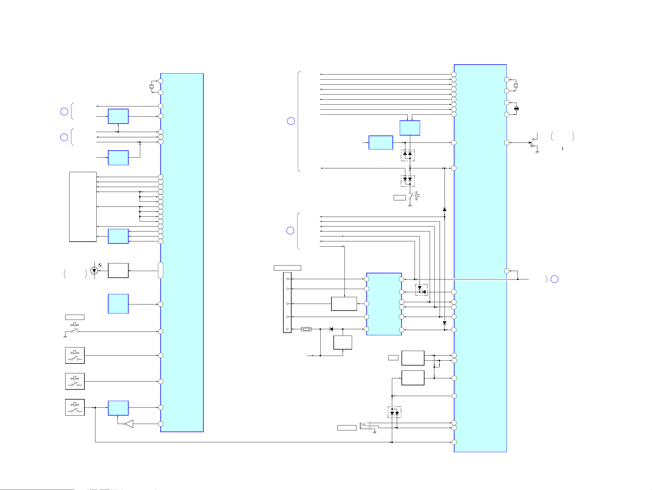
5-4. BLOCK DIAGRAM
– DISPLAY Section –
(Page 25)
(Page 25)
E
J
DISP_RX
DISP_TX
DISP_FLS_W
DISP_IF
DISP_RST
FL +3.3V
FLUORESCENT
INDICATOR
TUBE
FL701
BUS
SWITCH
IC604
VOLTAGE
DETECT
IC702
OR GATE
IC705
X701
5MHz
FRONT PANEL CONTROLLER
IC704
X1
1312X2
BUS_TX
25
BUS_RX
26
FLS WRT
75
SH_IF
18
RESET#
14
FL_SO1
51
FL_SO2
41
FL_SO3
54
FL_CKO1
52
FL_CKI2
42
FL_CKI3
55
BK
39
EDGE_TGR1
27
EDGE_TGR2
50
GCP_TGR3
46
LATCH
37
GCP1
30
GCP2
47
GCP3
45
– MAIN Section –
(Page 25)
(Page 24)
L
B
MAS_RX
MAS_TX
MAS_FLS
MAS_POW
SH_POW
SH_RST
DOOR_SW
NOSE_SW
MAS_RST
RESET
SYS_RST
BUS_ON
UNI_CLK
UNI_SI
UNI_SO
BU_IN
LINK_OFF
BU +3.3V
RESET SIGNAL
GENERATOR
IC502
D503
D511
S601
RESET
OR GATE
IC503
D506
SYSTEM CONTROLLER
GUI_TX
26
GUI_RX
25
FLASH_W
66
MAS_PW
27
GUI_SW
28
GUI_RST
18
DOOR_SW
68
NOSE_SW
3
RST_PROTECT
76
RAMBU
67
RESET
75
IC501 (3/4)
XIN
XOUT
OSCIN
OSCOUT
AREASEL0
MEX-BT5000
77
78
81
80
98
X502
32.768kHz
X501
18.432MHz
BU +3.3V
S503
FREQUENCY
SELECT
10k
9k
LED801 – 803
BLUETOOTH
INDICATOR
ENC702 (1/3)
PUSH LIST
S703 – S708
ENC702 (2/3), S709 – S714
S701, 702, 901
LED DRIVE
Q801 – 803
REMOTE
CONTROL
RECEIVER
IC703
BUS
SWITCH
IC701
Q701
71, 73, 74
57
77
91
89
90
72
BT_LED1,
BT_LED2,
BT_LED3
SIRCS
ENTER
KEY2
KEY1
KEY0
KEY0_SW
CNP102
BUS CONTROL IN
B-DATA
B-CLK
BUS-ON
RESET
+BATT
SONY BUS INTERFACE
IC102
5
4
6
2
7
BU B+
BUS ON/OFF
SWITCH
Q108, 109, 111
D125TH351
BATTERY
CHECK
REMOTE IN
Q110
CNJ351
DATA
6
I/O
CLK
4
BUS
1
ON
RST
2
BATT
3
DATA IN
DATA OUT
D501
B-CHK
CLK-IN
BUSON
RST-IN
VOL
10
D121
9
8
11
12
13
ROTARY
ENCODER
ENC702 (3/3)
KEY ACTIVE
SWITCH
Q501
D507
57
56
58
85
20
29
30
50
74
89
41
UNISO
UNISI
UNICLK
BUSON
SYSRST
RE_IN0
RE_IN1
KEY ACK
AD_ON
RC_IN1
RC_IN0
BU-IN
52
B-CHK
N
(Page 28)
MEX-BT5000
KEYIN0
39
2727
 Loading...