

Page 1
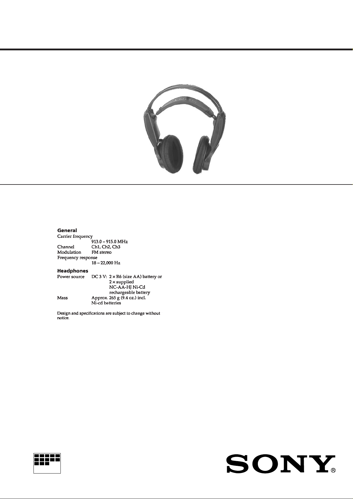
MDR-RF950
SERVICE MANUAL
Ver 1.0 1998. 06
MDR-RF950 is headphones
in MDR-RF950RK.
SPECIFICATIONS
US Model
Canadian Model
TABLE OF CONTENTS
1. GENERAL ................................................................. 2
2. DISASSEMBLY ......................................................... 3
3. ELECTRICAL ADJUSTMENTS
3-1. Checking/Adjusting Receiving Frequency ..................... 5
3-2. Checking/Adjusting Degree of Modulation
of Main Carrier (L + R) .................................................. 6
3-3. Checking/Adjusting Separation...................................... 7
4. DIAGRAMS
4-1. Printed W iring Boards..................................................... 11
4-2. Schematic Diagram......................................................... 13
5. EXPLODED VIEWS................................................ 15
6. ELECTRICAL PARTS LIST ............................... 17
Notes on chip component replacement
• Never reuse a disconnected chip component.
• Notice that the minus side of a tantalum capacitor may be damaged by heat.
WIRELESS STEREO HEADPHONES
MICROFILM
Page 2
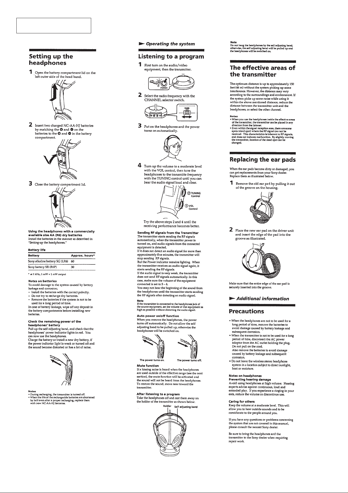
This section is extracted from
instruction manual.
SECTION 1
GENERAL
– 2 –
Page 3
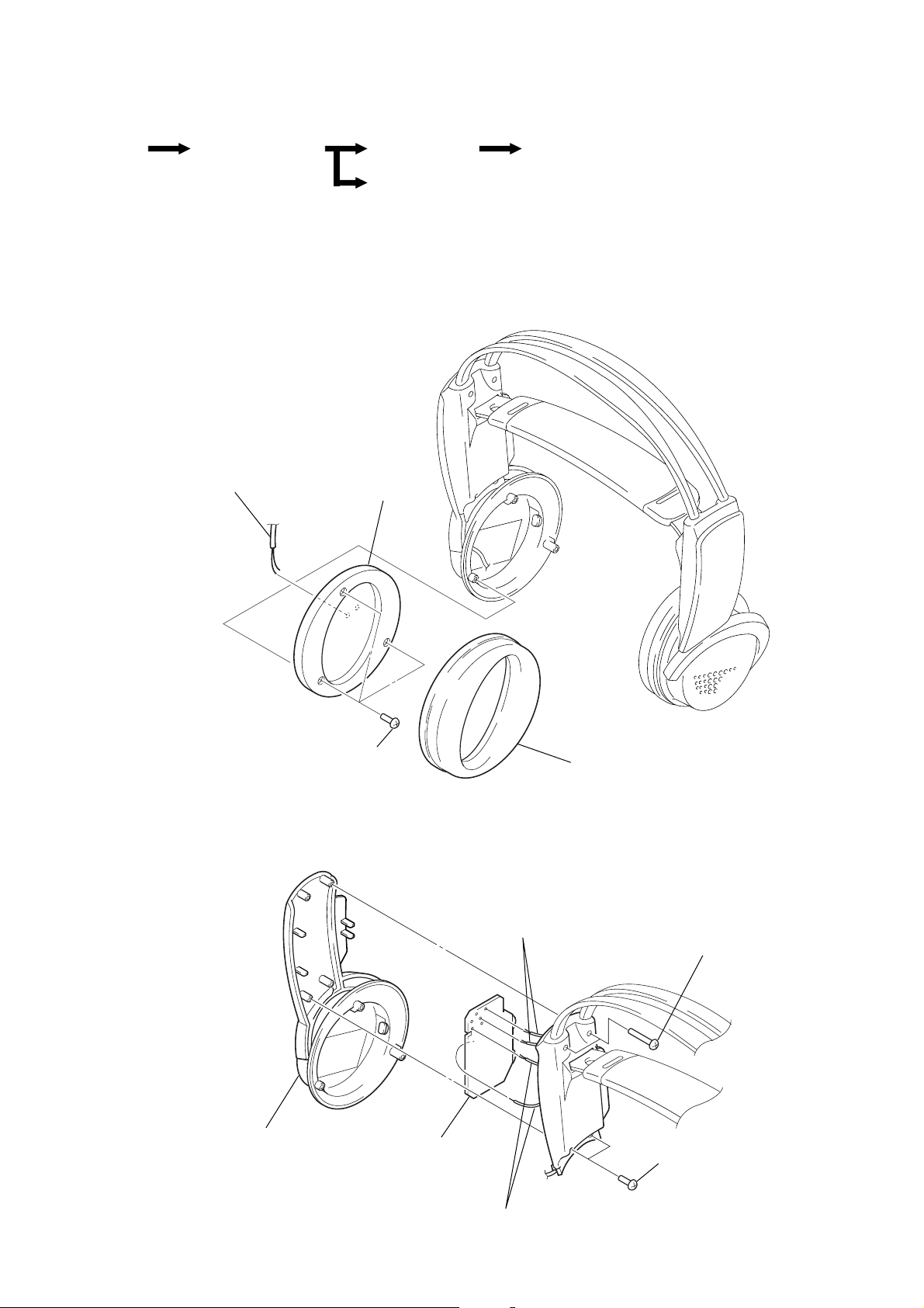
• This set can be disassembled in the order shown below.
SECTION 2
DISASSEMBLY
SET FRONT PLATE ASSY
Note: Follow the disassembly procedure in the numerical order given.
RX-BASE BOARD SW BOARD
HANGER COVER (L)
FRONT PLATE ASSY
4
Remove two solders
of driver lead.
3
front plate assy
RX-BASE BOARD
2
hanger cover (R)
2
three screws
(P2
1
×
6)
3
Remove four solders
of leads.
4
RX-BASE board
ear pad
1
two screws
(P2
1
two screws
(P2
×
6)
×
10)
3
Remove three solders
of leads.
– 3 –
Page 4

SW BOARD
y
)
2
screw (P2 × 6)
3
switch support
5
SW board
1
two head bands
4
head cushion ass
HANGER COVER (L)
1
two screws
×
10)
(P2
1
two screws
×
6)
(P2
3
Remove two solders
of battery lead.
2
hanger cover (L
– 4 –
Page 5

SECTION 3
ELECTRICAL ADJUSTMENTS
Note:
1. The adjustments should be performed in the order given.
2. The transmitter (TMR-RF950R) already checked and adjusted should be used.
3-1. Receiving Frequency Check and Adjustment
Preparation:
AF OSC
+
+
–
–
DC voltmeter
oscilloscope
+
–
ATT
+
–
600
AUDIO IN (Lch)
1 kHz 316 mVrms
TMR-RF950R
Transmitter
Ω
MDR-RF950
5 m
Headphones
[RX-BASE board] – Conductor Side –
Procedure:
1. Set the channel of the transmitter to CH2.
2. Turn OFF the noise filter switch on the transmitter.
3. Enter 1 kHz 316 mVrms signal only to the Lch on the transmitter.
4. Place the transmitter away from the headphone (MDR-RF950) more than 5 m.
5. Set the volume control (RV301) on the RX-BASE board to the minimum position.
6. Set the tuning control (RV302) on the RX-BASE board to the center position.
7. Connect a DC voltmeter and an oscilloscope between IC301 pin @¡ and ground on the RX-BASE board.
8. After confirming that demodulated 1 kHz waveform (about 13 mV) appears on the oscilloscope, check that the DC v oltmeter indicates
DC1 V to 1.2 V.
9. If demodulated 1 kHz waveform does not appear on the oscilloscope, or if the voltage is out of the specif ied value, adjust the air-core
coil (L301) on the RX-BASE board so that the demodulated 1 kHz waveform appears on the oscilloscope, and under this condition,
adjust finely the air-core coil (L301) so that the DC voltmeter indicates DC1.1 V.
10. Finally, check that signals are receiv ed when the channel is changed ov er to CH1/CH3 on the transmitter , then when the tuning control
(RV302) on the RX-BASE board is rotated.
Adjustment Location: RX-BASE board (See page 9.)
– 5 –
Page 6

3-2. Degree of Modulation of Main Carrier (L + R) Check and Adjustment
Preparation:
AF OSC
ATT
+
+
–
–
AC voltmeter
oscilloscope
+
–
+
–
600
AUDIO IN (Lch)
1 kHz 316 mVrms
TMR-RF950R
Transmitter
Ω
MDR-RF950
Headphones
[RX-BASE board] – Conductor Side –
Procedure:
1. Set the channel of the transmitter to CH2.
2. Turn OFF the noise filter switch on the transmitter.
3. Enter 1 kHz 316 mVrms signal only to the Lch on the transmitter.
4. Set the volume control (RV301) on the RX-BASE board to the minimum position.
5. Connect an AC voltmeter and an oscilloscope between IC 301 pin @¡ and ground on the RX-BASE board.
6. Rotating the tuning control (RV302) on the RX-BASE board, receive signals.
7. After confirming that demodulated 1 kHz waveform appears on the oscilloscope, check that the AC voltmeter indicates 12 mVrms to
15 mVrms.
8. If out of the specified value, rotate RV404 on the TX-BASE board in the transmitter (TMR-RF950R) so as to attain 13.5 mVrms.
Adjustment Location: TX-BASE board in the transmitter (TMR-RF950R) (See page 8.)
– 6 –
Page 7

3-3. Separation Check and Adjustment
Preparation:
AF OSC
+
+
–
–
AC voltmeter
oscilloscope
ATT
+
–
600
Ω
AUDIO IN (Lch or Rch)
1 kHz 316 mVrms
TMR-RF950R
Transmitter
MDR-RF950
Headphones
+
–
[RX-BASE board] – Conductor Side –
Procedure:
1. Set the channel of the transmitter to CH2.
2. Turn OFF the noise filter switch on the transmitter.
3. Enter 1 kHz 316 mVrms signal only to the Lch on the transmitter.
4. Connect an AC voltmeter and an oscilloscope to the Lch speaker output (both ends of MDD01) on the RX-BASE board.
5. Rotating the tuning control (RV302) on the RX-BASE boar d, receive signals.
6. Adjust the volume control (RV301) on the RX-BASE board so that the Lch speaker output (both ends of MDD01) on the RX-BASE
board becomes 155 mVrms.
7. Connect an AC voltmeter and oscilloscope to the Rch speaker output (both ends of MDD02) and measure voltage.
8. Check that a difference in speaker output level between Lch and Rch (i. e., separation) is o v er 20 dB. If not o v er 20 dB, rotate RV303
on the RX-BASE board to minimize the Rch output, then reconfirm that a difference in speaker output level between Lch and Rch is
over 20 dB.
9. Enter 1kHz 316 mVrms signal only to the Rch on the transmitter.
10. Adjust the volume control (R V301) on the RX-B ASE board so that the Rch speak er output (voltage across MDD02) on the RX-BASE
board become 155 mVrms.
11. Connect an AC voltmeter and oscilloscope to the Lch speaker output (both ends of MDD01) and measure voltage.
12. Check that a difference in speaker output level between Lch and Rch (i.e., separation) is over 20 dB.
Adjustment Location: RX-BASE board (See page 9.)
– 7 –
Page 8

Adjustment Location:
Transmitter (TMR-RF950R)
RV404
Degree of
Modulation of
Main Carrier (L + R)
Adjustment
NOISE FILTER
OFF
[TX-BASE board] – Component Side –
S401
˜
ON
J402
(Rch)
J403
(Lch)
S402
CH2
CHANNEL
˜
CH1
CH3
˜
– 8 –
Page 9

SECTION 4
DIAGRAMS
Headphone (MDR-RF950)
[RX-BASE board] – Component Side –
RV302
TUNING
MAX
RV301
VOL
MIN
[RX-BASE board] – Conductor Side –
IC301
• IC Block Diagrams
IC301 CXA1611N-T4
L301
Receiving Frequency
Adjustment
RV303
Separation Adjustment
IC302 LA4533M
POWER
1
PWR
R-IN
GND
L-IN
REG
SWITCH
2
3
BIAS
4
5 6
AMP
AMP
MUTE
10
MUTE
R-OUT
9
8
GND
7
L-OUT
VCC
– 9 – – 10 –
Page 10

Page 11

Page 12

SECTION 5
EXPLODED VIEWS
NOTE:
• -XX and -X mean standardized parts, so they
may have some difference from the original
one.
• Color Indication of Appearance Parts
Example:
KNOB, BALANCE (WHITE) . . . (RED)
↑↑
Parts Color Cabinet's Color
(1) HEADPHONE (R) SECTION
6
5
14
• Items marked “*” are not stocked since they
are seldom required for routine service. Some
delay should be anticipated when ordering
these items.
• The mechanical parts with no reference number in the exploded views are not supplied.
9
10
11
(2) HEADPHONE (L) SECTION
52
56
57
63
62
61
58
64
60
7
8
4
MDD02
2
Ref. No. Part No. Description Remark
1 4-971-700-01 PAD, EAR
2 X-4950-190-1 PLATE (R) ASSY, FRONT
3 4-999-774-01 REGISTER, HOUSING
4 4-999-773-01 HOUSING (R)
5 4-999-769-11 COVER (R), HANGER
* 6 A-4542-518-A RX-BASE BOARD, COMPLETE
7 4-210-255-01 SUPPORT, SWITCH
* 8 1-670-527-11 SW BOARD
3
14
14
12
13
1
Ref. No. Part No. Description Remark
9 4-999-767-01 HANGER (R)
10 7-685-106-19 SCREW +P 2X10 TYPE2 NON-SLIT
11 4-966-791-11 STOPPER (UPPER)
12 4-966-792-11 STOPPER (LOWER)
13 3-318-203-62 SCREW (B1.7X4), TAPPING
14 7-685-104-19 SCREW +P 2X6 TYPE2 NON-SLIT
MDD02 1-505-117-21 DRIVER (R-CH)
55
69
54
51
53
68
Ref. No. Part No. Description Remark
51 4-999-771-01 SUSPENDER
52 4-978-518-02 BASE, SUSPENDER
53 4-978-519-01 CUSHION, HEAD
54 3-318-203-62 SCREW (B1.7X4), TAPPING
55 4-966-792-11 STOPPER (LOWER)
56 4-966-791-11 STOPPER (UPPER)
57 4-999-765-01 BAND, HEAD
58 7-685-106-19 SCREW +P 2X10 TYPE2 NON-SLIT
59 4-999-766-11 HANGER (L) (US)
59 4-999-766-21 HANGER (L) (Canadian)
60 4-210-258-01 TERMINAL (MIDWAY), BATTERY
59
65
66
67
MDD01
69
Ref. No. Part No. Description Remark
61 4-210-257-01 TERMINAL (-), BATTERY
62 4-210-256-01 TERMINAL (+), BATTERY
63 4-999-770-11 LID, BATTERY CASE
64 4-999-768-01 COVER (L), HANGER
65 4-999-772-01 HOUSING (L)
66 4-999-774-01 REGISTER, HOUSING
67 X-4950-189-1 PLATE (L) ASSY, FRONT
68 4-971-700-01 PAD, EAR
69 7-685-104-19 SCREW +P 2X6 TYPE2 NON-SLIT
MDD01 1-505-117-21 DRIVER (L-CH)
– 15 – – 16 –
Page 13

SECTION 6
ELECTRICAL PARTS LIST
FE RX-BASE
NOTE:
• Due to standardization, replacements in the
parts list may be different from the parts specified in the diagrams or the components used
on the set.
• -XX and -X mean standardized parts, so they
may have some difference from the original
one.
• RESISTORS
All resistors are in ohms.
METAL: Metal-film resistor.
METAL OXIDE: Metal oxide-film resistor.
F: nonflammable
Ref. No. Part No. Description Remark
FE BOARD
********
(Included in RX-BASE BOARD, COMPLETE)
< CAPACITOR >
C1 1-162-906-11 CERAMIC CHIP 1.5PF 0.25PF 50V
C2 1-162-927-11 CERAMIC CHIP 100PF 5% 50V
C3 1-162-964-11 CERAMIC CHIP 0.001uF 10% 50V
C4 1-162-908-11 CERAMIC CHIP 3PF 0.25PF 50V
C5 1-162-918-11 CERAMIC CHIP 18PF 5% 50V
C6 1-162-964-11 CERAMIC CHIP 0.001uF 10% 50V
C8 1-162-910-11 CERAMIC CHIP 5PF 0.25PF 50V
C9 1-162-920-11 CERAMIC CHIP 27PF 5% 50V
C10 1-162-905-11 CERAMIC CHIP 1PF 0.25PF 50V
C12 1-162-915-11 CERAMIC CHIP 10PF 0.5PF 50V
C13 1-162-905-11 CERAMIC CHIP 1PF 0.25PF 50V
C14 1-162-925-11 CERAMIC CHIP 68PF 5% 50V
C15 1-162-927-11 CERAMIC CHIP 100PF 5% 50V
C16 1-162-906-11 CERAMIC CHIP 1.5PF 0.25PF 50V
C17 1-162-964-11 CERAMIC CHIP 0.001uF 10% 50V
C20 1-162-964-11 CERAMIC CHIP 0.001uF 10% 50V
C21 1-162-964-11 CERAMIC CHIP 0.001uF 10% 50V
C23 1-162-906-11 CERAMIC CHIP 1.5PF 0.25PF 50V
C24 1-162-906-11 CERAMIC CHIP 1.5PF 0.25PF 50V
C28 1-162-917-11 CERAMIC CHIP 15PF 5% 50V
C30 1-162-921-11 CERAMIC CHIP 33PF 5% 50V
C39 1-162-964-11 CERAMIC CHIP 0.001uF 10% 50V
C40 1-162-909-11 CERAMIC CHIP 4PF 0.25PF 50V
C41 1-162-910-11 CERAMIC CHIP 5PF 0.25PF 50V
C43 1-162-964-11 CERAMIC CHIP 0.001uF 10% 50V
• Items marked “*” are not stocked since they
are seldom required for routine service.
Some delay should be anticipated when ordering these items.
• SEMICONDUCTORS
In each case, u: µ, for example:
uA. . : µA. . uPA. . : µPA. .
uPB. . : µPB. . uPC. . : µPC. .
uPD. . : µPD. .
• CAPACITORS
uF: µF
• COILS
uH: µH
When indicating parts by reference
number, please include the board.
Ref. No. Part No. Description Remark
L2 1-469-237-21 INDUCTOR 0.68uH
L3 1-414-665-11 INDUCTOR CHIP 12nH
L4 1-414-665-11 INDUCTOR CHIP 12nH
L5 1-414-660-11 INDUCTOR CHIP 4.7nH
L6 1-414-660-11 INDUCTOR CHIP 4.7nH
< TRANSISTOR >
Q1 8-729-046-22 FET 3SK240 (TE85L)
Q3 8-729-230-81 TRANSISTOR 2SC3606
Q4 8-729-232-73 TRANSISTOR 2SC4320 (TE85L)
< RESISTOR >
R1 1-216-845-11 METAL CHIP 100K 5% 1/16W
R4 1-216-853-11 METAL CHIP 470K 5% 1/16W
R5 1-216-845-11 METAL CHIP 100K 5% 1/16W
R7 1-216-809-11 METAL CHIP 100 5% 1/16W
R8 1-218-293-11 RES,CHIP 24K 5% 1/16W
R10 1-216-845-11 METAL CHIP 100K 5% 1/16W
R11 1-216-810-11 METAL CHIP 120 5% 1/16W
R12 1-216-809-11 METAL CHIP 100 5% 1/16W
< CAPACITOR >
THC1 1-104-511-51 CERAMIC 0.001uF
THC2 1-111-231-43 CERAMIC 2PF 99%
THC3 1-111-231-43 CERAMIC 2PF 99%
< SAW RESONANTOR >
X1 1-767-906-11 RESONANTOR, SAW
************************************************************
C44 1-162-927-11 CERAMIC CHIP 100PF 5% 50V
< IC >
IC1 8-759-469-63 IC S-81215SGUP-DQK-T1
< RESISTOR >
JR1 1-216-864-11 METAL CHIP 0 5% 1/16W
JR2 1-216-864-11 METAL CHIP 0 5% 1/16W
< COIL >
L1 1-469-237-21 INDUCTOR 0.68uH
* A-4542-518-A RX-BASE BOARD, COMPLETE
************************
(Including FE BOARD)
< CAPACITOR >
C301 1-126-154-11 ELECT 47uF 20% 6.3V
C302 1-164-489-11 CERAMIC CHIP 0.22uF 10% 16V
C303 1-163-239-11 CERAMIC CHIP 33PF 5% 50V
C306 1-163-037-11 CERAMIC CHIP 0.022uF 10% 25V
C307 1-163-121-11 CERAMIC CHIP 150PF 5% 50V
C309 1-126-572-11 ELECT 4.7uF 20% 35V
C310 1-164-004-11 CERAMIC CHIP 0.1uF 10% 25V
– 17 –
Page 14

RX-BASE
Ref. No. Part No. Description Remark
C311 1-163-243-11 CERAMIC CHIP 47PF 5% 50V
C312 1-163-021-00 CERAMIC CHIP 0.01uF 10% 50V
C313 1-163-113-00 CERAMIC CHIP 68PF 5% 50V
C314 1-163-125-00 CERAMIC CHIP 220PF 5% 50V
C315 1-124-233-11 ELECT 10uF 20% 16V
C316 1-163-023-00 CERAMIC CHIP 0.015uF 5% 50V
C317 1-163-021-00 CERAMIC CHIP 0.01uF 10% 50V
C318 1-164-346-11 CERAMIC CHIP 1uF 16V
C319 1-164-505-11 CERAMIC CHIP 2.2uF 16V
C320 1-164-346-11 CERAMIC CHIP 1uF 16V
C321 1-164-346-11 CERAMIC CHIP 1uF 16V
C322 1-124-242-00 ELECT 33uF 20% 25V
C323 1-163-243-11 CERAMIC CHIP 47PF 5% 50V
C324 1-164-004-11 CERAMIC CHIP 0.1uF 10% 25V
C325 1-164-004-11 CERAMIC CHIP 0.1uF 10% 25V
C326 1-124-434-00 ELECT 220uF 20% 4V
C327 1-124-434-00 ELECT 220uF 20% 4V
C328 1-124-434-00 ELECT 220uF 20% 4V
C329 1-164-346-11 CERAMIC CHIP 1uF 16V
C330 1-163-009-11 CERAMIC CHIP 0.001uF 10% 50V
C331 1-163-224-11 CERAMIC CHIP 7PF 0.25PF 50V
C332 1-163-113-00 CERAMIC CHIP 68PF 5% 50V
C333 1-163-021-00 CERAMIC CHIP 0.01uF 10% 50V
Ref. No. Part No. Description Remark
JR311 1-216-295-00 SHORT 0
JR312 1-216-295-00 SHORT 0
JR313 1-216-295-00 SHORT 0
JR314 1-216-295-00 SHORT 0
JR315 1-216-295-00 SHORT 0
JR316 1-216-296-00 SHORT 0
< COIL >
L301 1-416-796-11 COIL, AIR-CORE
L302 1-412-933-11 INDUCTOR 0.33uH
< TRANSISTOR >
Q301 8-729-230-49 TRANSISTOR 2SC2712-YG
Q302 8-729-230-49 TRANSISTOR 2SC2712-YG
Q303 8-729-230-49 TRANSISTOR 2SC2712-YG
Q304 8-729-230-49 TRANSISTOR 2SC2712-YG
Q305 8-729-230-49 TRANSISTOR 2SC2712-YG
Q306 8-729-920-31 TRANSISTOR DTC343TK
Q307 8-729-230-49 TRANSISTOR 2SC2712-YG
Q308 8-729-040-78 TRANSISTOR DTA124GKA-T146
Q309 8-729-027-36 TRANSISTOR DTA143XKA-T146
< RESISTOR >
C334 1-124-233-11 ELECT 10uF 20% 16V
C335 1-163-245-11 CERAMIC CHIP 56PF 5% 50V
C336 1-163-245-11 CERAMIC CHIP 56PF 5% 50V
C337 1-163-021-00 CERAMIC CHIP 0.01uF 10% 50V
C338 1-163-037-11 CERAMIC CHIP 0.022uF 10% 50V
C339 1-164-489-11 CERAMIC CHIP 0.22uF 10% 16V
C340 1-164-346-11 CERAMIC CHIP 1uF 16V
C341 1-164-161-11 CERAMIC CHIP 2200PF 5% 50V
C350 1-163-021-00 CERAMIC CHIP 0.01uF 10% 50V
< CERAMIC FILTER >
CF301 1-577-588-11 FILTER, CERAMIC
CF302 1-567-163-11 FILTER, CERAMIC
< DIODE >
D301 8-719-045-99 DIODE RD2.2M-T1B
D302 8-719-002-81 DIODE 1T363
D303 8-719-066-69 LED BR2434D (POWER)
< IC >
IC301 8-752-066-93 IC CXA1611N-T4
IC302 8-759-802-75 IC LA4533M
IC303 8-759-195-02 IC TC7S86F-TE85L
IC304 8-759-096-87 IC TC7WU04FU(TE12R)
< SHORT >
JR301 1-216-296-00 SHORT 0
JR302 1-216-296-00 SHORT 0
JR303 1-216-296-00 SHORT 0
JR304 1-216-296-00 SHORT 0
JR305 1-216-296-00 SHORT 0
JR306 1-216-295-00 SHORT 0
JR308 1-216-295-00 SHORT 0
JR309 1-216-295-00 SHORT 0
JR310 1-216-295-00 SHORT 0
R301 1-216-121-00 RES,CHIP 1M 5% 1/10W
R302 1-216-101-00 METAL CHIP 150K 5% 1/10W
R303 1-216-081-00 METAL CHIP 22K 5% 1/10W
R304 1-216-061-00 METAL CHIP 3.3K 5% 1/10W
R305 1-216-103-00 RES,CHIP 180K 5% 1/10W
R306 1-216-113-00 METAL CHIP 470K 5% 1/10W
R307 1-216-097-00 RES,CHIP 100K 5% 1/10W
R308 1-216-073-00 METAL CHIP 10K 5% 1/10W
R309 1-216-089-00 RES,CHIP 47K 5% 1/10W
R310 1-216-041-00 METAL CHIP 470 5% 1/10W
R311 1-216-049-11 RES,CHIP 1K 5% 1/10W
R312 1-216-113-00 METAL CHIP 470K 5% 1/10W
R313 1-216-061-00 METAL CHIP 3.3K 5% 1/10W
R314 1-216-051-00 RES,CHIP 1.2K 5% 1/10W
R315 1-216-067-00 METAL CHIP 5.6K 5% 1/10W
R316 1-216-061-00 METAL CHIP 3.3K 5% 1/10W
R317 1-216-061-00 METAL CHIP 3.3K 5% 1/10W
R318 1-216-067-00 METAL CHIP 5.6K 5% 1/10W
R319 1-216-061-00 METAL CHIP 3.3K 5% 1/10W
R320 1-216-097-00 RES,CHIP 100K 5% 1/10W
R321 1-216-093-00 METAL CHIP 68K 5% 1/10W
R322 1-216-093-00 METAL CHIP 68K 5% 1/10W
R323 1-216-125-00 METAL CHIP 1.5M 5% 1/10W
R324 1-216-025-00 RES,CHIP 100 5% 1/10W
R325 1-216-057-00 METAL CHIP 2.2K 5% 1/10W
R326 1-216-061-00 METAL CHIP 3.3K 5% 1/10W
R327 1-216-025-00 RES,CHIP 100 5% 1/10W
R328 1-216-077-00 METAL CHIP 15K 5% 1/10W
R329 1-216-001-00 METAL CHIP 10 5% 1/10W
R330 1-216-001-00 METAL CHIP 10 5% 1/10W
R331 1-216-097-00 RES,CHIP 100K 5% 1/10W
R334 1-216-097-00 RES,CHIP 100K 5% 1/10W
R335 1-216-029-00 METAL CHIP 150 5% 1/10W
R342 1-216-062-11 RES,CHIP 3.6K 5% 1/10W
R345 1-216-089-11 METAL CHIP 47K 5% 1/10W
– 18 –
Page 15

RX-BASE SW
Ref. No. Part No. Description Remark
R348 1-216-069-00 METAL CHIP 6.8K 5% 1/10W
R349 1-216-001-00 METAL CHIP 10 5% 1/10W
R350 1-216-053-00 METAL CHIP 1.5K 5% 1/10W
< VARIABLE RESISTOR >
RV301 1-223-968-11 RES, VAR, CARBON 20K/20K (VOL)
RV302 1-225-641-11 RES, VAR, CARBON 10K (TUNING)
RV303 1-238-857-11 RES, ADJ, CERMET 22K
************************************************************
* 1-670-527-11 SW BOARD
*********
< SWITCH >
SW1 1-572-467-61 SWITCH, PUSH (1 KEY) (POWER)
************************************************************
MISCELLANEOUS
**************
MDD01 1-505-117-21 DRIVER (L-CH)
MDD02 1-505-117-21 DRIVER (R-CH)
Ref. No. Part No. Description Remark
– 19 –
Page 16

MDR-RF950
9-924-925-11
Sony Corporation
Personal A&V Products Company
– 20 –
Printed in Singapore © 1998. 6
98F057022-1
Published by Quarity Engineering Dept.
(Shibaura)
 Loading...