

Page 1
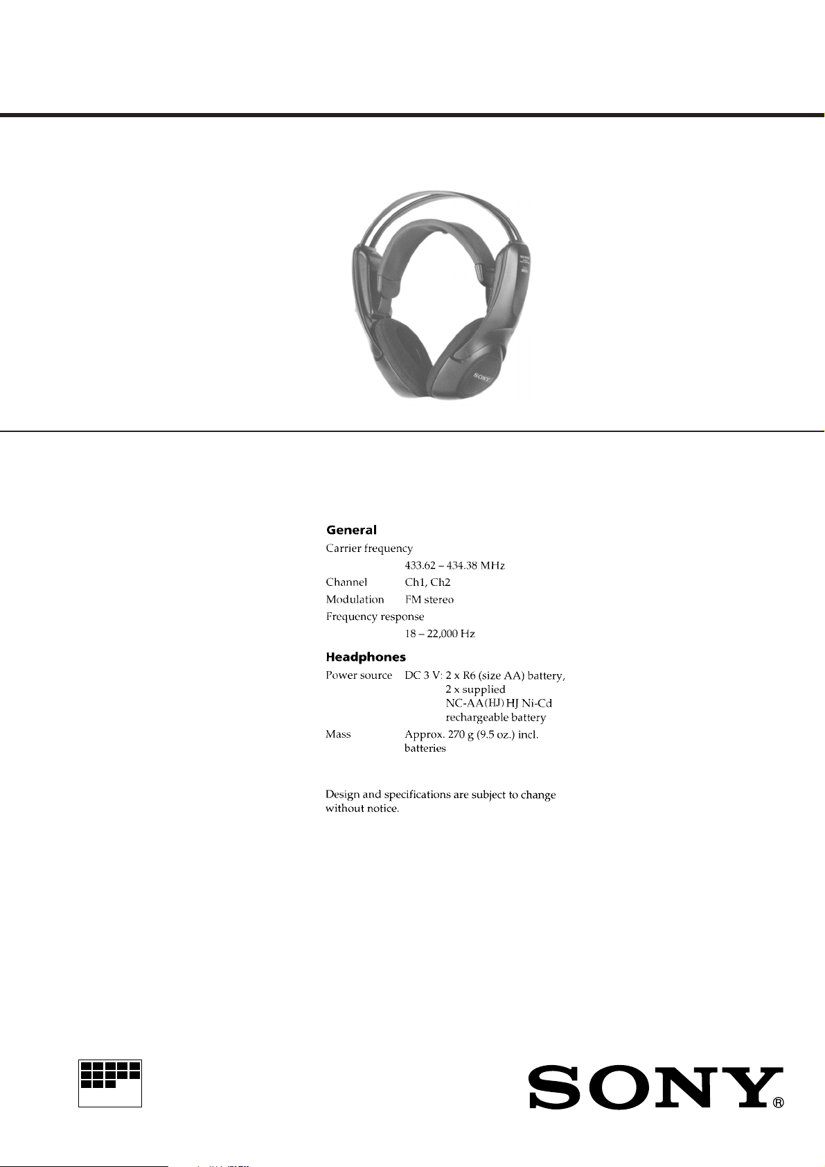
MDR-RF940R
SERVICE MANUAL
MDR-RF940R is headphones
in MDR-RF940RK.
SPECIFICATIONS
AEP Model
Notes on chip component replacement
• Never reuse a disconnected chip component.
• Notice that the minus side of a tantalum capacitor may be dam-
aged by heat.
Flexible Circuit Board Repairing
• Keep the temperature of the soldering iron around 270 ˚C during
repairing.
• Do not touch the soldering iron on the same conductor of the
circuit board (within 3 times).
• Be careful not to apply force on the conductor when soldering or
unsoldering
MICROFILM
HEADPHONES
Page 2
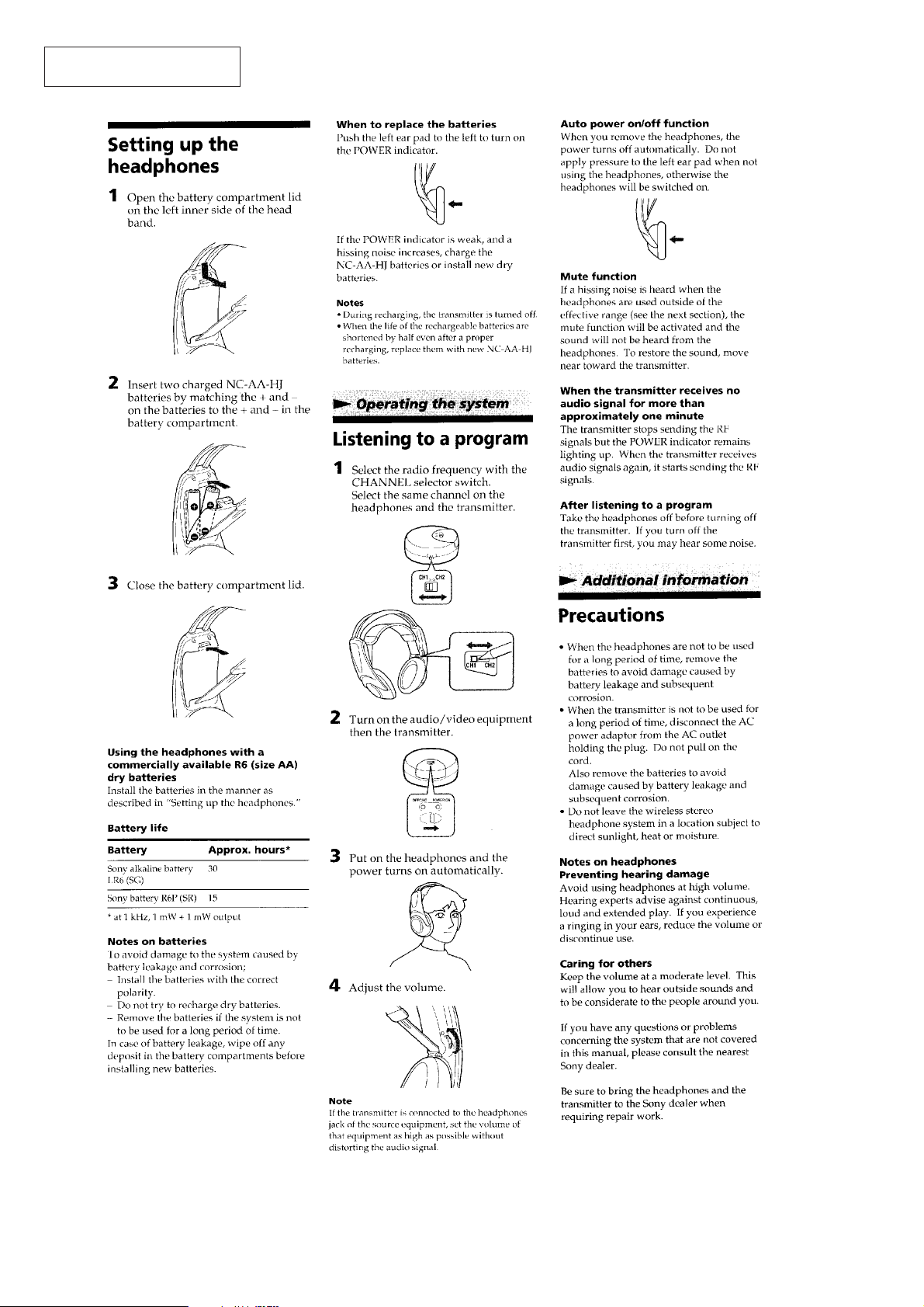
This section is extracted from
instruction manual.
SECTION 1
GENERAL
– 2 –
Page 3
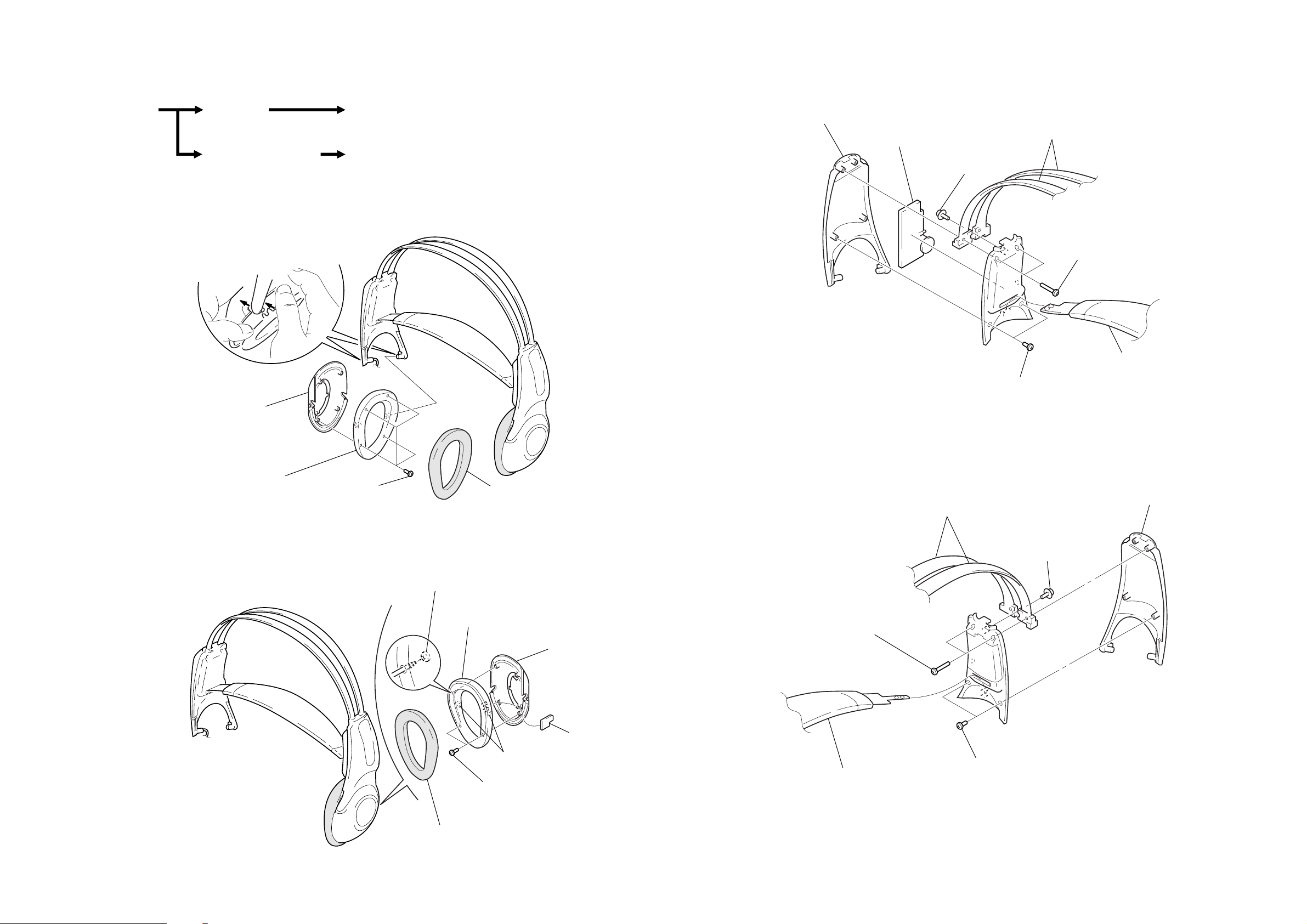
SECTION 2
DISASSEMBLY
MDR-RF940R
• This set can be disassembled in the order shown below.
SET
Note: Follow the disassembly procedure in the numerical order given.
HOUSING (R)
(Page 3)
HOUSING (L), SW BOARD
(Page 3)
HANGER (R), RX BOARD
(Page 4)
HANGER (L)
(Page 4)
HOUSING (R)
3
two bosses
5
housing (R)
HANGER (R), RX BOARD
3
hanger (R)
4
RX board
5
screw
(PWH 2.6
×
6)
1
two screws
(P 2
6
two head bands
2
two screws
(P 2
×
10)
7
suspender ass’y
×
6)
4
front plate (R)
HOUSING (L), SW BOARD
2
four screws
(P 2
×
6)
3
screw (P 2 × 6)
1
ear pad
5
front plate (L)
2
two screws
(P 2
4
two bosses
×
6)
6
housing (L)
7
SW board
HANGER (L)
2
two screws
(P 2
6
suspender ass’y
×
10)
5
two head bands
1
two screws
×
(P 2
6)
4
screw
(PWH 2.6
3
hanger (L)
×
6)
– 3 –
1
ear pad
– 4 –
Page 4
Page 5
Page 6

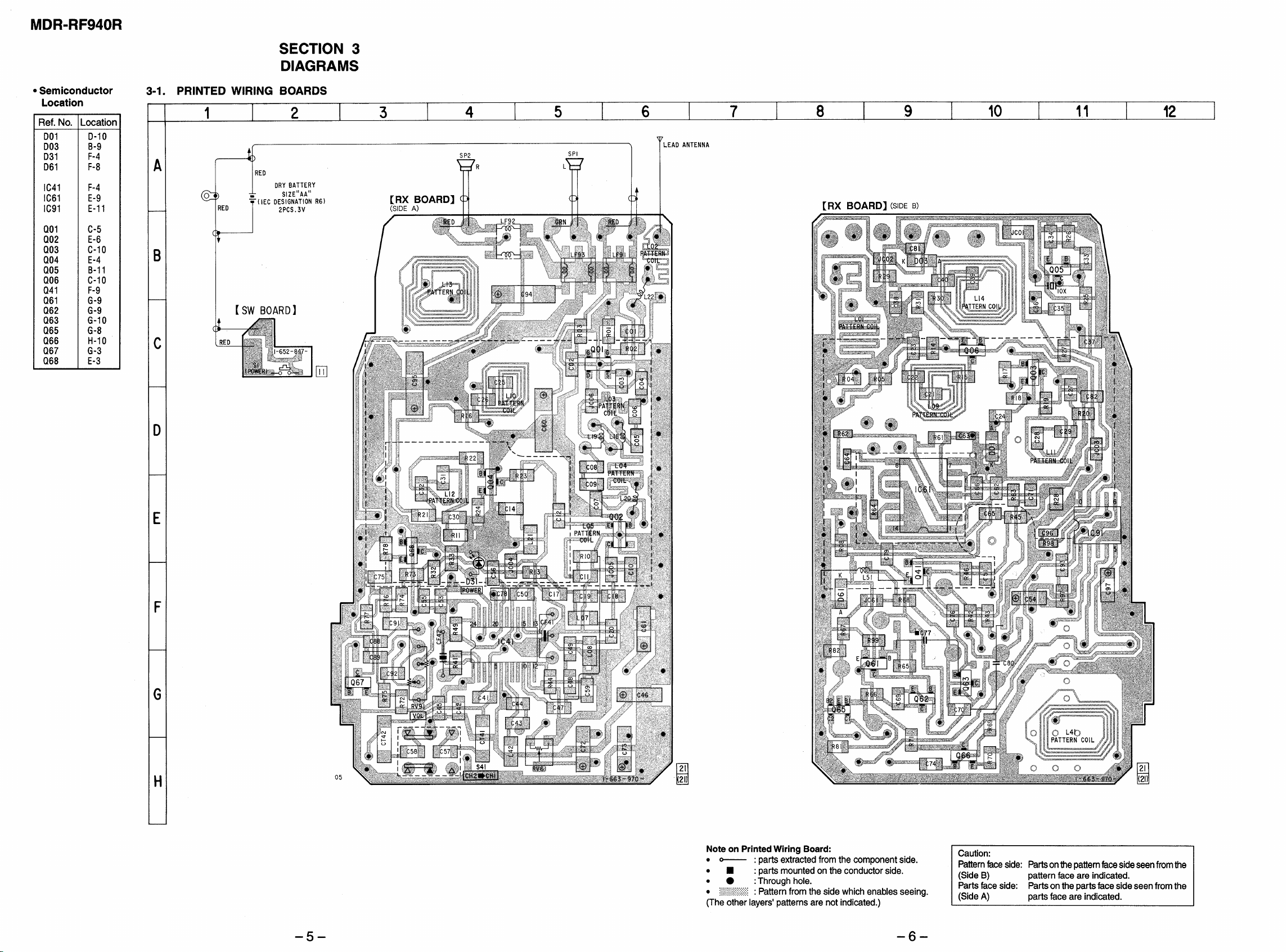
MDR-RF940R
SECTION 4
EXPLODED VIEWS
NOTE:
• -XX and -X mean standardized parts, so they
may have some difference from the original one.
• Color Indication of Appearance Parts
Example:
KNOB, BALANCE (WHITE) . . . (RED)
↑↑
Parts Color Cabinet's Color
(1) HEADPHONE (R) SECTION
5
• Items marked “*” are not stocked since they
are seldom required for routine service. Some
delay should be anticipated when ordering these
items.
• The mechanical parts with no reference number in the exploded views are not supplied.
• Hardware (# mark) list is given in the last of
the electrical parts list.
6
#3
7
#2
4
#1
8
9
10
3
2
SP2
1
#1
11
Ref. No. Part No. Description Remark
1 4-966-797-11 PLATE (R), FRONT
2 4-966-794-11 HOUSING (R)
3 4-966-800-11 CAP (R)
* 4 4-967-909-01 SCREEN (CAP)
5 4-980-054-01 HANGER (R)
* 6 A-4542-441-A RX BOARD, COMPLETE
Ref. No. Part No. Description Remark
7 4-966-807-21 COVER (HANGER R)
8 4-984-694-01 PLATE (CHANNEL), INDICATION
9 4-966-785-01 REGISTER, FRONT
10 4-966-786-01 SCREEN (FRONT)
11 4-966-811-01 PAD, EAR
SP2 1-505-117-21 DRIVER (R CH)
– 10 –
Page 7

(2) HEADPHONE (L) SECTION
60
59
56
53
54
55
57
#2
#1
#1
66
68
#1
58
#4
65
#3
67
#5
61
62
63
64
SP1
52
Ref. No. Part No. Description Remark
51 4-966-801-11 COVER (SWITCH)
52 4-966-811-01 PAD, EAR
53 4-966-786-01 SCREEN (FRONT)
54 4-966-785-01 REGISTER, FRONT
55 4-966-808-01 LID, BATTERY CASE
56 A-4540-414-A SUSPENDER ASSY
57 4-987-591-01 SPRING, BATTERY COIL
58 4-966-806-01 COVER (HANGER L)
59 4-966-795-01 BAND, HEAD
60 4-980-053-01 HANGER (L)
51
Ref. No. Part No. Description Remark
61 4-987-590-01 TERMINAL (+), BATTERY
62 4-987-592-01 TERMINAL (COMMONNESS), BATTERY
63 4-966-799-11 CAP (L)
64 4-966-793-11 HOUSING (L)
65 4-966-796-11 PLATE (L), FRONT
* 66 1-663-968-21 SW BOARD
* 67 4-967-909-01 SCREEN (CAP)
68 3-722-156-01 SPRING, COMPRESSION
SP1 1-505-117-21 DRIVER (L CH)
– 11 –
Page 8

RX
SECTION 5
ELECTRICAL PARTS LIST
NOTE:
• Due to standardization, replacements in the
parts list may be different from the parts specified in the diagrams or the components used on
the set.
• -XX and -X mean standardized parts, so they
may have some difference from the original one.
• RESISTORS
All resistors are in ohms.
METAL: Metal-film resistor.
METAL OXIDE: Metal oxide-film resistor.
F: nonflammable
Ref. No. Part No. Description Remark
* A-4542-441-A RX BOARD, COMPLETE
*******************
3-701-437-21 WASHER
< CAPACITOR >
C01 1-163-113-00 CERAMIC CHIP 68PF 5% 50V
C02 1-164-232-11 CERAMIC CHIP 0.01uF 50V
C03 1-164-232-11 CERAMIC CHIP 0.01uF 50V
C04 1-164-232-11 CERAMIC CHIP 0.01uF 50V
C05 1-163-090-00 CERAMIC CHIP 7PF 50V
C06 1-163-090-00 CERAMIC CHIP 7PF 50V
C07 1-164-232-11 CERAMIC CHIP 0.01uF 50V
C08 1-163-091-00 CERAMIC CHIP 8PF 50V
C09 1-163-090-00 CERAMIC CHIP 7PF 50V
C10 1-163-099-00 CERAMIC CHIP 18PF 5% 50V
C11 1-164-232-11 CERAMIC CHIP 0.01uF 50V
C12 1-163-091-00 CERAMIC CHIP 8PF 50V
C14 1-163-141-00 CERAMIC CHIP 0.001uF 5% 50V
C17 1-164-232-11 CERAMIC CHIP 0.01uF 50V
C18 1-163-235-11 CERAMIC CHIP 22PF 5% 50V
C19 1-163-098-00 CERAMIC CHIP 16PF 5% 50V
C20 1-163-085-00 CERAMIC CHIP 2PF 50V
C21 1-163-237-11 CERAMIC CHIP 27PF 5% 50V
C22 1-163-102-00 CERAMIC CHIP 24PF 5% 50V
C23 1-164-232-11 CERAMIC CHIP 0.01uF 50V
C24 1-164-232-11 CERAMIC CHIP 0.01uF 50V
C25 1-163-237-11 CERAMIC CHIP 27PF 5% 50V
C26 1-163-241-11 CERAMIC CHIP 39PF 5% 50V
C27 1-164-232-11 CERAMIC CHIP 0.01uF 50V
C28 1-163-102-00 CERAMIC CHIP 24PF 5% 50V
C29 1-163-096-00 CERAMIC CHIP 13PF 5% 50V
C30 1-164-232-11 CERAMIC CHIP 0.01uF 50V
C31 1-163-231-11 CERAMIC CHIP 15PF 5% 50V
C32 1-163-098-00 CERAMIC CHIP 16PF 5% 50V
C33 1-163-253-11 CERAMIC CHIP 120PF 5% 50V
C34 1-163-253-11 CERAMIC CHIP 120PF 5% 50V
C35 1-163-120-00 CERAMIC CHIP 130PF 5% 50V
C36 1-163-251-11 CERAMIC CHIP 100PF 5% 50V
C37 1-164-232-11 CERAMIC CHIP 0.01uF 50V
C38 1-164-232-11 CERAMIC CHIP 0.01uF 50V
C39 1-163-120-00 CERAMIC CHIP 130PF 5% 50V
C40 1-163-121-00 CERAMIC CHIP 150PF 5% 50V
• Items marked “*” are not stocked since they
are seldom required for routine service.
Some delay should be anticipated when ordering these items.
• SEMICONDUCTORS
In each case, u: µ, for example:
uA. . : µA. . uP A. . : µP A. .
uPB. . : µPB. . uPC. . : µPC. .
uPD. . : µPD. .
• CAP ACITORS
uF: µF
• COILS
uH: µH
When indicating parts by reference
number, please include the board.
Ref. No. Part No. Description Remark
C41 1-163-224-11 CERAMIC CHIP 7PF 0.25PF 50V
C42 1-163-100-00 CERAMIC CHIP 20PF 5% 50V
C43 1-163-243-11 CERAMIC CHIP 47PF 5% 50V
C44 1-163-245-11 CERAMIC CHIP 56PF 5% 50V
C45 1-164-232-11 CERAMIC CHIP 0.01uF 50V
C46 1-124-779-00 ELECT CHIP 10uF 20% 16V
C47 1-164-232-11 CERAMIC CHIP 0.01uF 50V
C48 1-163-251-11 CERAMIC CHIP 100PF 5% 50V
C49 1-163-245-11 CERAMIC CHIP 56PF 5% 50V
C50 1-164-232-11 CERAMIC CHIP 0.01uF 50V
C51 1-163-259-91 CERAMIC CHIP 220PF 5% 50V
C53 1-163-023-00 CERAMIC CHIP 0.015uF 5% 50V
C54 1-135-259-11 TANTALUM CHIP 10uF 20% 6.3V
C55 1-164-232-11 CERAMIC CHIP 0.01uF 50V
C56 1-164-346-11 CERAMIC CHIP 1uF 16V
C57 1-163-239-11 CERAMIC CHIP 33PF 5% 50V
C58 1-163-239-11 CERAMIC CHIP 33PF 5% 50V
C59 1-163-253-11 CERAMIC CHIP 120PF 5% 50V
C60 1-126-246-11 ELECT CHIP 220uF 20% 4V
C61 1-126-607-11 ELECT CHIP 47uF 20% 4V
C62 1-164-489-11 CERAMIC CHIP 0.22uF 10% 16V
C63 1-162-925-11 CERAMIC CHIP 68PF 5% 50V
C64 1-164-217-11 CERAMIC CHIP 150PF 5% 50V
C65 1-163-243-11 CERAMIC CHIP 47PF 5% 50V
C66 1-163-243-11 CERAMIC CHIP 47PF 5% 50V
C69 1-164-489-11 CERAMIC CHIP 0.22uF 10% 16V
C70 1-164-489-11 CERAMIC CHIP 0.22uF 10% 16V
C71 1-163-037-11 CERAMIC CHIP 0.022uF 10% 25V
C72 1-126-603-11 ELECT CHIP 4.7uF 20% 35V
C73 1-126-603-11 ELECT CHIP 4.7uF 20% 35V
C74 1-107-725-11 CERAMIC CHIP 0.1uF 10% 16V
C75 1-164-505-11 CERAMIC CHIP 2.2uF 16V
C76 1-163-249-11 CERAMIC CHIP 82PF 5% 50V
C77 1-162-282-31 CERAMIC 100PF 10% 50V
C78 1-163-249-11 CERAMIC 82PF 5% 50V
C79 1-164-182-11 CERAMIC 0.0033uF 10% 50V
C80 1-162-294-31 CERAMIC 0.001uF 10% 50V
C81 1-162-964-11 CERAMIC CHIP 0.001uF 10% 50V
C82 1-163-253-11 CERAMIC CHIP 120PF 5% 50V
C88 1-163-017-00 CERAMIC CHIP 0.0047uF 5% 50V
C89 1-163-017-00 CERAMIC CHIP 0.0047uF 5% 50V
C91 1-164-346-11 CERAMIC CHIP 1uF 16V
C92 1-164-346-11 CERAMIC CHIP 1uF 16V
– 12 –
Page 9

RX
Ref. No. Part No. Description Remark
C93 1-107-725-11 CERAMIC CHIP 0.1uF 10% 16V
C94 1-126-246-11 ELECT CHIP 220uF 20% 4V
C95 1-126-246-11 ELECT CHIP 220uF 20% 4V
C96 1-107-826-11 CERAMIC CHIP 0.1uF 10% 16V
C97 1-104-847-11 TANTALUM CHIP 22uF 20% 4V
< FILTER >
CF41 1-577-588-11 FILTER, CERAMIC (10.7MHz)
CF42 1-567-163-11 FILTER, CERAMIC (10.7MHz)
< TRIMMER >
CT41 1-141-327-11 CAP, CHIP TYPE TRIMMER 10PF
CT42 1-141-327-11 CAP, CHIP TYPE TRIMMER 10PF
< DIODE >
D01 8-719-421-40 DIODE MA77
D03 8-719-421-40 DIODE MA77
D31 8-719-023-84 LED HLMP-1801 (POWER)
D61 8-719-045-99 DIODE RD2.2M-T1B
< IC >
IC41 8-752-072-65 IC CXA1611N-T4
IC61 8-759-239-23 IC TC74HC86AF
IC91 8-759-802-75 IC LA4533M
< CHIP CONDUCTOR >
JC01 1-216-296-00 CONDUCTOR, CHIP (3216)
JC02 1-216-295-00 CONDUCTOR, CHIP (2012)
JC03 1-216-295-00 CONDUCTOR, CHIP (2012)
JC04 1-216-295-00 CONDUCTOR, CHIP (2012)
JC05 1-216-295-00 CONDUCTOR, CHIP (2012)
JC06 1-216-295-00 CONDUCTOR, CHIP (2012)
JC12 1-216-295-00 CONDUCTOR, CHIP (2012)
JC61 1-216-295-00 CONDUCTOR, CHIP (2012)
< COIL >
L07 1-412-933-11 INDUCTOR, CHIP 0.33uH
L08 1-412-933-11 INDUCTOR, CHIP 0.33uH
L18 1-416-384-21 COIL, AIR-CORE (MDR)
L19 1-416-384-21 COIL, AIR-CORE (MDR)
L20 1-416-384-31 COIL, AIR-CORE (MDR)
L21 1-412-933-11 INDUCTOR CHIP 0.33uH
L22 1-416-384-11 COIL, AIR-CORE (MDR)
L42 1-412-933-11 INDUCTOR CHIP 0.33uH
L51 1-410-171-11
MICRO INDUCTOR 1mH
Ref. No. Part No. Description Remark
Q41 8-729-200-63 TRANSISTOR 2SC2712L-TE85R
Q61 8-729-200-63 TRANSISTOR 2SC2712L-TE85R
Q62 8-729-027-36 TRANSISTOR DTA143XKA-T146
Q63 8-729-040-78 TRANSISTOR DTA124GKA-T146
Q65 8-729-020-92 TRANSISTOR XN1504-TX
Q66 8-729-200-63 TRANSISTOR 2SC2712L-TE85R
Q67 8-729-200-63 TRANSISTOR 2SC2712L-TE85R
Q68 8-729-200-63 TRANSISTOR 2SC2712L-TE85R
< RESISTOR/CHIP CONDUCTOR >
R01 1-216-093-00 METAL CHIP 68K 5% 1/10W
R02 1-216-091-00 METAL CHIP 56K 5% 1/10W
R03 1-216-073-00 METAL CHIP 10K 5% 1/10W
R04 1-216-001-00 METAL CHIP 10 5% 1/10W
R05 1-216-001-00 METAL CHIP 10 5% 1/10W
R08 1-216-125-00 METAL CHIP 1.5M 5% 1/10W
R10 1-216-029-00 METAL CHIP 150 5% 1/10W
R11 1-216-069-00 METAL CHIP 6.8K 5% 1/10W
R13 1-216-001-00 METAL CHIP 10 5% 1/10W
R14 1-216-001-00 METAL CHIP 10 5% 1/10W
R15 1-216-001-00 METAL CHIP 10 5% 1/10W
R16 1-216-093-00 METAL CHIP 68K 5% 1/10W
R17 1-216-001-00 METAL CHIP 10 5% 1/10W
R18 1-216-009-00 METAL CHIP 22 5% 1/10W
R19 1-216-295-00 CONDUCTOR, CHIP (2012)
R20 1-216-001-00 METAL CHIP 10 5% 1/10W
R21 1-216-069-00 METAL CHIP 6.8K 5% 1/10W
R22 1-216-001-00 METAL CHIP 10 5% 1/10W
R23 1-216-001-00 METAL CHIP 10 5% 1/10W
R24 1-216-009-00 METAL CHIP 22 5% 1/10W
R25 1-216-091-00 METAL CHIP 56K 5% 1/10W
R26 1-216-033-00 METAL CHIP 220 5% 1/10W
R27 1-216-001-00 METAL CHIP 10 5% 1/10W
R28 1-216-029-00 METAL CHIP 150 5% 1/10W
R29 1-216-093-00 METAL CHIP 68K 5% 1/10W
R30 1-216-001-00 METAL CHIP 10 5% 1/10W
R31 1-216-009-00 METAL CHIP 22 5% 1/10W
R32 1-216-053-00 METAL CHIP 1.5K 5% 1/10W
R33 1-216-069-00 METAL CHIP 6.8K 5% 1/10W
R41 1-216-025-00 METAL CHIP 100 5% 1/10W
R42 1-216-093-00 METAL CHIP 68K 5% 1/10W
R43 1-216-093-00 METAL CHIP 68K 5% 1/10W
R44 1-216-057-00 METAL CHIP 2.2K 5% 1/10W
R45 1-216-061-00 METAL CHIP 3.3K 5% 1/10W
R46 1-216-125-00 METAL CHIP 1.5M 5% 1/10W
< LINE FILTER >
LF91 1-411-236-11 FILTER, EMI
LF92 1-411-236-11 FILTER, EMI
LF93 1-411-236-11 FILTER, EMI
< TRANSISTOR >
Q01 8-729-231-66 FET 3SK207
Q02 8-729-232-73 TRANSISTOR 2SC4320(TE85L)
Q03 8-729-209-45 TRANSISTOR 2SC3120-TE85R
Q04 8-729-230-81 TRANSISTOR 2SC3606
Q05 8-729-209-45 TRANSISTOR 2SC3120-TE85R
Q06 8-729-209-45 TRANSISTOR 2SC3120-TE85R
R49 1-216-097-00 METAL CHIP 100K 5% 1/10W
R61 1-216-079-00 METAL CHIP 18K 5% 1/10W
R62 1-216-841-11 METAL CHIP 47K 5% 1/16W
R63 1-216-061-00 METAL CHIP 3.3K 5% 1/10W
R64 1-216-841-11 METAL CHIP 47K 5% 1/16W
R65 1-216-113-00 METAL CHIP 470K 5% 1/10W
R66 1-216-089-00 METAL CHIP 47K 5% 1/10W
R67 1-216-089-00 METAL CHIP 47K 5% 1/10W
R68 1-216-295-91 CONDUCTOR, CHIP (2012)
R69 1-216-113-00 METAL CHIP 470K 5% 1/10W
R70 1-216-041-00 METAL CHIP 470 5% 1/10W
R71 1-216-061-00 METAL CHIP 3.3K 5% 1/10W
R72 1-216-049-00 METAL CHIP 1K 5% 1/10W
– 13 –
Page 10

MDR-RF940R
RX
Ref. No. Part No. Description Remark
R73 1-216-051-00 METAL CHIP 1.2K 5% 1/10W
R74 1-216-067-00 METAL CHIP 5.6K 5% 1/10W
R75 1-216-061-00 METAL CHIP 3.3K 5% 1/10W
R76 1-216-067-00 METAL CHIP 5.6K 5% 1/10W
R77 1-216-061-00 METAL CHIP 3.3K 5% 1/10W
R78 1-216-061-00 METAL CHIP 3.3K 5% 1/10W
R81 1-216-097-00 METAL CHIP 100K 5% 1/10W
R82 1-216-097-00 METAL CHIP 100K 5% 1/10W
R97 1-216-308-00 METAL CHIP 4.7 5% 1/10W
R98 1-216-793-11 METAL CHIP 4.7 5% 1/16W
R99 1-216-101-00 METAL CHIP 150K 5% 1/10W
RV61 1-238-857-11 RES, ADJ, CERMET 22K
RV91 1-241-853-11 RES, VAR, CARBON 10K/10K (VOL)
S41 1-692-729-21 SWITCH, SLIDE (CH1-CH2)
X01 1-767-457-11 VIBRATOR, CRYSTAL (14.1875MHz)
************************************************************
SW
< VARIABLE RESISTOR >
< SWITCH >
< VIBRATOR >
* 1-663-968-21 SW BOARD
S1 1-572-467-61 SWITCH, PUSH (1 KEY) (POWER)
************************************************************
SP1 1-505-117-21 DRIVER (L CH)
SP2 1-505-117-21 DRIVER (R CH)
************************************************************
#1 7-685-104-19 SCREW +P 2X6 TYPE2 NON-SLIT
#2 7-685-106-19 SCREW +P 2X10 TYPE2 NON-SLIT
#3 7-621-770-67 SCREW +PWH 2.6X6
#4 7-623-505-01 LUG, 2
#5 7-685-102-19 SCREW +P 2X4 TYPE2 NON-SLIT
*********
< SWITCH >
MISCELLANEOUS
**************
**************
HARDWARE LIST
**************
9-923-238-11
Sony Corporation
Personal A&V Products Company
– 14 –
Printed in Hungary © 1997. 8
97H057546-1
Published by Quality Engineering Dept.
(Shibaura)
Page 11

MDR-RF940R
SERVICE MANUAL
Ver. 1.0 1998. 05
SUPPLEMENT-1
File this supplement with the service manual.
Subject:
1. Modification
2. Electrical Adjustments
AEP Model
Page 12

1. MODIFICATION
• Countermeasure for distortion and white noise.
Improvement of MDR-RF940R Increase the value of C65 of RX
board.
Add a 22 pF capacitor in parallel with C65.
Please use the following part.
Chip ceramic capacitor 22 pF
1-163-235-11 or 1-163-235-91
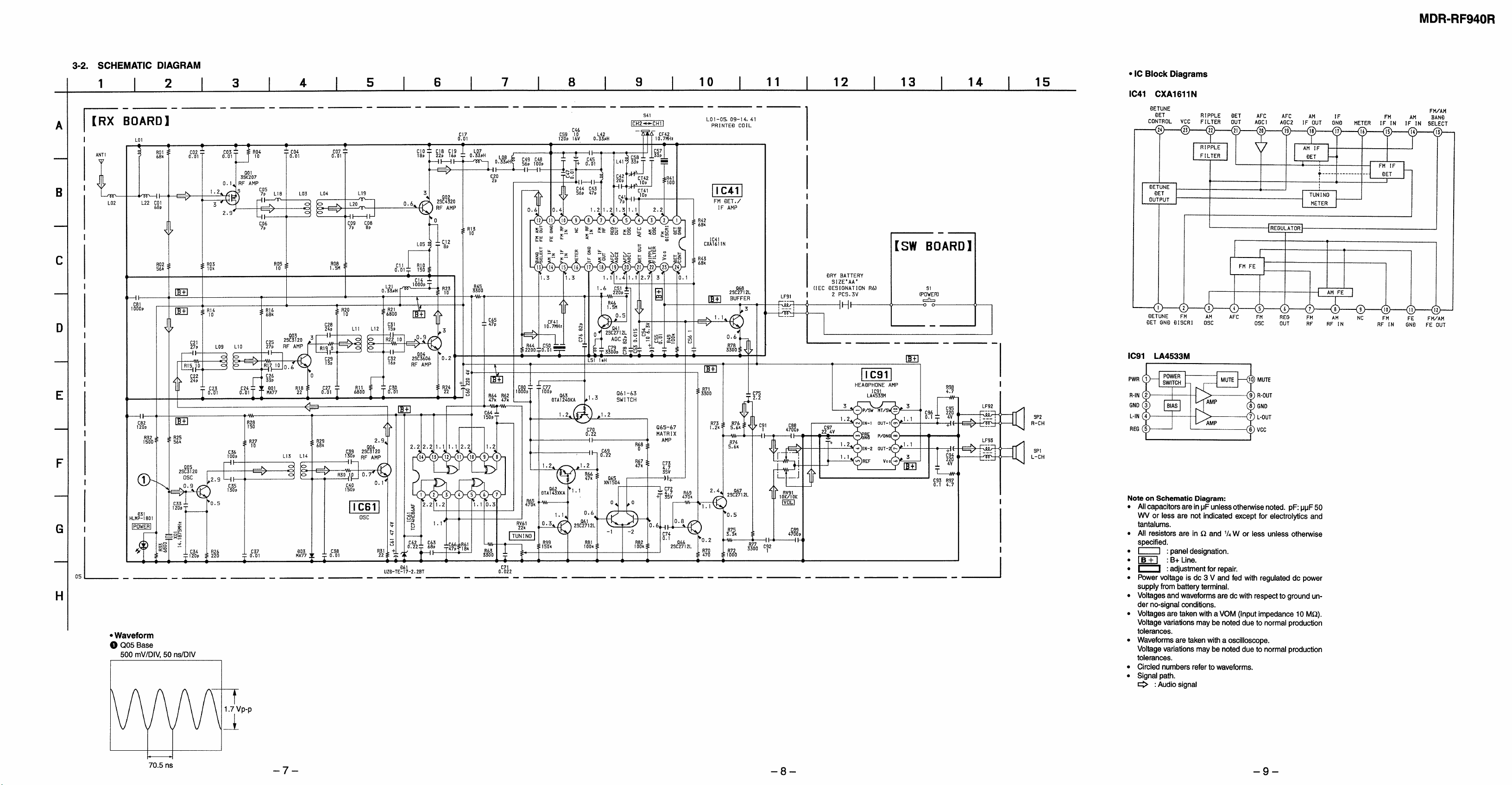
SCHEMATIC DIAGRAM
• Original Service Manual page 7.
(Location C – E, 6 – 8)
!: Added portion
[RX Board]
^
PRINTED WIRING BOARD
• Original Service Manual page 6.
(Location D – F, 9 – 11)
!: Added portion
[RX Board] – Side B –
C65
22 pF
@
RX Board
– 2 –
Page 13

2. ELECTRICAL ADJUSTMENTS
[RX Board] – Side A –
volume
IC41
CT42
CT41
spectrum
analyzer
pick-up coil
CH1: CT41
CH2: CT42
Be careful not to set the pick-up coil
too close to the RX board.
Note:
• Perform countermeasure for distortion before adjustments.
Adjust and confirm the unit by following procedure shown below after this countermeasure.
• Please adjust the transmitter and the headphone together.
Procedure for Measurements and Adjustments
Lastly, we would like to explain the procedure for adjusting this model. As this model adopts a Stereo Modulation method called “FMFM”, it is difficult to perform the adjustments with common measurement equipments.
The following adjustment should be performed with a spectrum analyzer.
Adjustments for Headphones
Reception frequency confirmation and adjustment
1) Prepare a pick-up coil (See the figure. 1) for measuring the local oscillation frequency of RX board.
Pick-up coil
BNC
coaxial cable
Figure 1.
2) Turn on the power of the adjusted transmitter.
3) Input a signal of 1 kHz 50 mVrms to Lch of the transmitter for avoiding AUTO OFF.
4) Set the pick-up coil to the RX board as the figure. 2.
One turn of
cupper wire
Diameter:
approx. 40 mm
5) Confirm and adjust the frequency by the spectrum analyzer.
CH1: Adjust CH1 to be the following value by turning CT41.
Adjusted value CH1=Main carrier frequency of Transmitter – (minus) 372.36 MHz
CH2: Adjust CH2 to be the following value by turning CT42.
Adjusted value CH2=Main carrier frequency of Transmitter – (minus) 372.36 MHz
Figure 2.
– 3 –
Page 14

r
r
MDR-RF940R
Adjustment for Separation
Preparation:
Procedure:
1) Input a signal of 400 Hz 316 mVrms only to Lch of the adjusted transmitter.
2) Turn RV91 on the RX board so that the speaker out of Lch becomes 155 mVrms.
3) Turn RV61 on the RX board so that the speaker out of Rch becomes minimum.
4) At this time, confirm the separation between Lch and Rch should be over 18 dB.
5) Then, input a signal of 400 Hz 316 mVrms only to Rch of the transmitter.
6) At this time, confirm the separation between Rch and Lch should be over 18 dB.
Adjustment Location: RX Board
Confirmation without a spectrum analyzer
Please confirm the units by following procedure shown below.
Here a series of procedure which can be performed without a spectrum analyzer is introduced.
Tuning frequency confirmation
Preparation:
Procedure:
1) Input any signal including music into TMR-RF940R and place the unit the point where is far from MDR-RF940R and place the unit in
a location where is far from by 5 m.
2) Measure the DC voltage at the test point TP2 of RX board of MDR-RF940R.
This DC voltage corresponds to the S-curve voltage of FM detection characteristics as shown below.
AF OSC
AF OSC
+
–
ATT
+
–
ATT
+
–
600
input plug (Lch or Rch)
400 Hz 316 mVrms
+
–
600
input plug
AF signal or music
TMR-RF940R
Transmitter
Ω
TMR-RF940R
Transmitter
Ω
5 m
MDR-RF940R
Headphones
speaker out (Lch or Rch)
MDR-RF940R
Headphones
AC voltmete
+
–
DC voltmete
+
–
RX Board TP2
Spec.
DC1.1
±
0.1 V
0
f
If tuned frequency is in the area covered by AFC, the center voltage changes when CT41 (channel 1) CT42 (channel 2) is turned.
Adjustment Location:
[RX Board] – Side A –
RV91
CT42
IC41
CT41
RV61
PRINTED WIRING BOARD
• MDR-RF940R Service Manual page 5.
(Location F – H, 4 – 6)
[RX Board] – Side A –
DC voltmeter
+
–
9-923-238-81
Sony Corporation
Personal A&V Products Company
– 4 –
Printed in Japan © 1998. 5
98E0539-1
Published by Quarity Engineering Dept.
(Shibaura)
 Loading...