

Sony MDRRF-930 Service manual
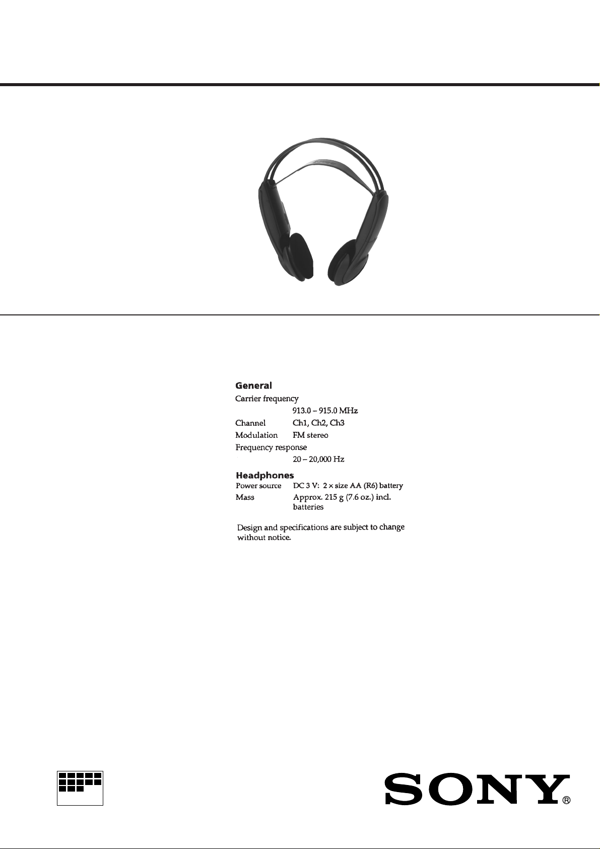
MDR-RF930
SERVICE MANUAL
Ver 1.0 1998. 06
MDR-RF930 is headphones
in MDR-RF930K.
SPECIFICATIONS
US Model
Canadian Model
MICROFILM
Notes on chip component replacement
• Never reuse a disconnected chip component.
• Notice that the minus side of a tantalum capacitor may be dam-
aged by heat.
WIRELESS STEREO HEADPHONES
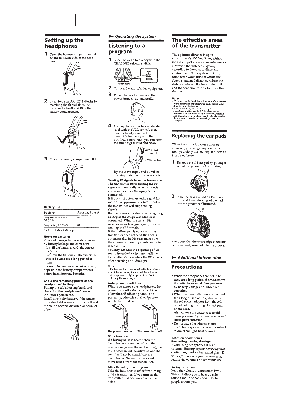
This section is extracted from
instruction manual.
SECTION 1
GENERAL
– 2 –
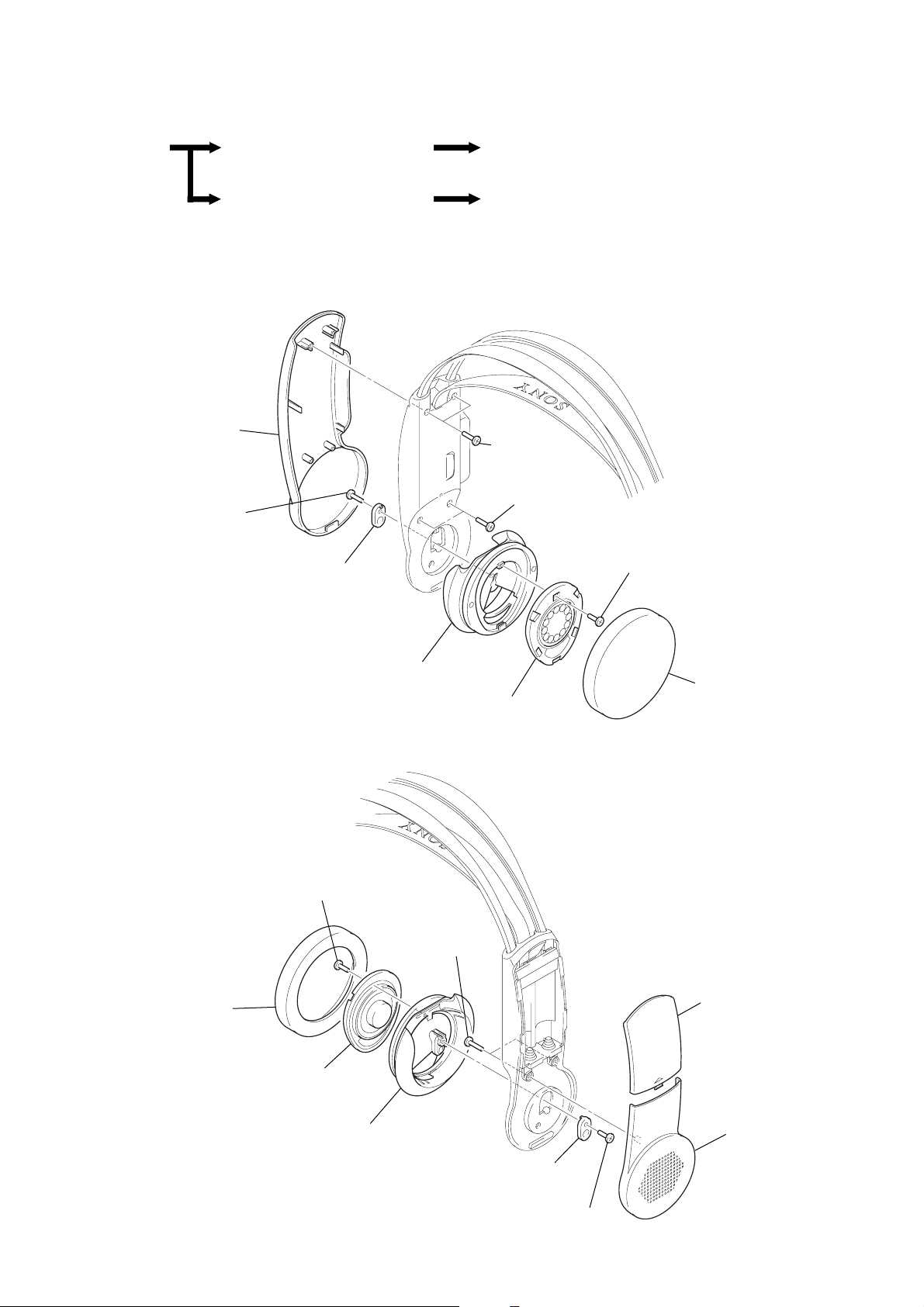
• This set can be disassembled in the order shown below.
SECTION 2
DISASSEMBLY
SET
Note: Follow the disassembly procedure in the numerical order given.
HOUSING (R) ASSY, HANGER (R)
HOUSING (L) ASSY, HANGER (L)
HOUSING (R) ASSY, HANGER (R)
5
hanger (R)
6
screw
(P 2 × 10)
7
ball shaft holder
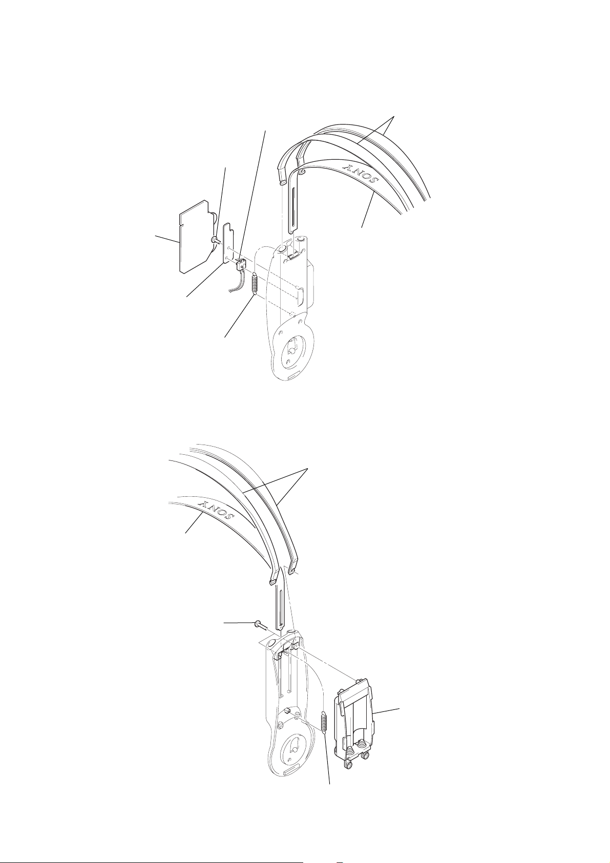
RX BOARD
BATTERY CASE
4
two screws
(P2 × 10)
4
two screws
(P2 × 6)
2
screw
(B1.7 × 4)
8
HOUSING (L) ASSY, HANGER (L)
2
screw
×
4)
(B1.7
1
ear pad
3
driver ( L-CH )
housing (R) assy
9
two screws
(P2
3
×
8)
driver (R-CH)
1
ear pad
4
battery cover
8
housing (L) assy
7
ball shaft holder
– 3 –
6
screw
(P2
5
hanger (L)
×
6)
RX BOARD
e
s
1
RX board
2
two screws (B1.7 × 4)
3
RX shield plate
5
tension spring
4
push (1 key) SWITCH
7
suspender assy
6
two head band
BATTERY CASE
5
suspender assy
1
two screws
×
10)
(P2
4
two head bands
2
battery cas
– 4 –
3
tension spring
SECTION 3
0
ELECTRICAL ADJUSTMENTS
Note:
1. The adjustments should be performed in the order given.
2. The transmitter (TMR-RF930) already checked and adjusted should be used.
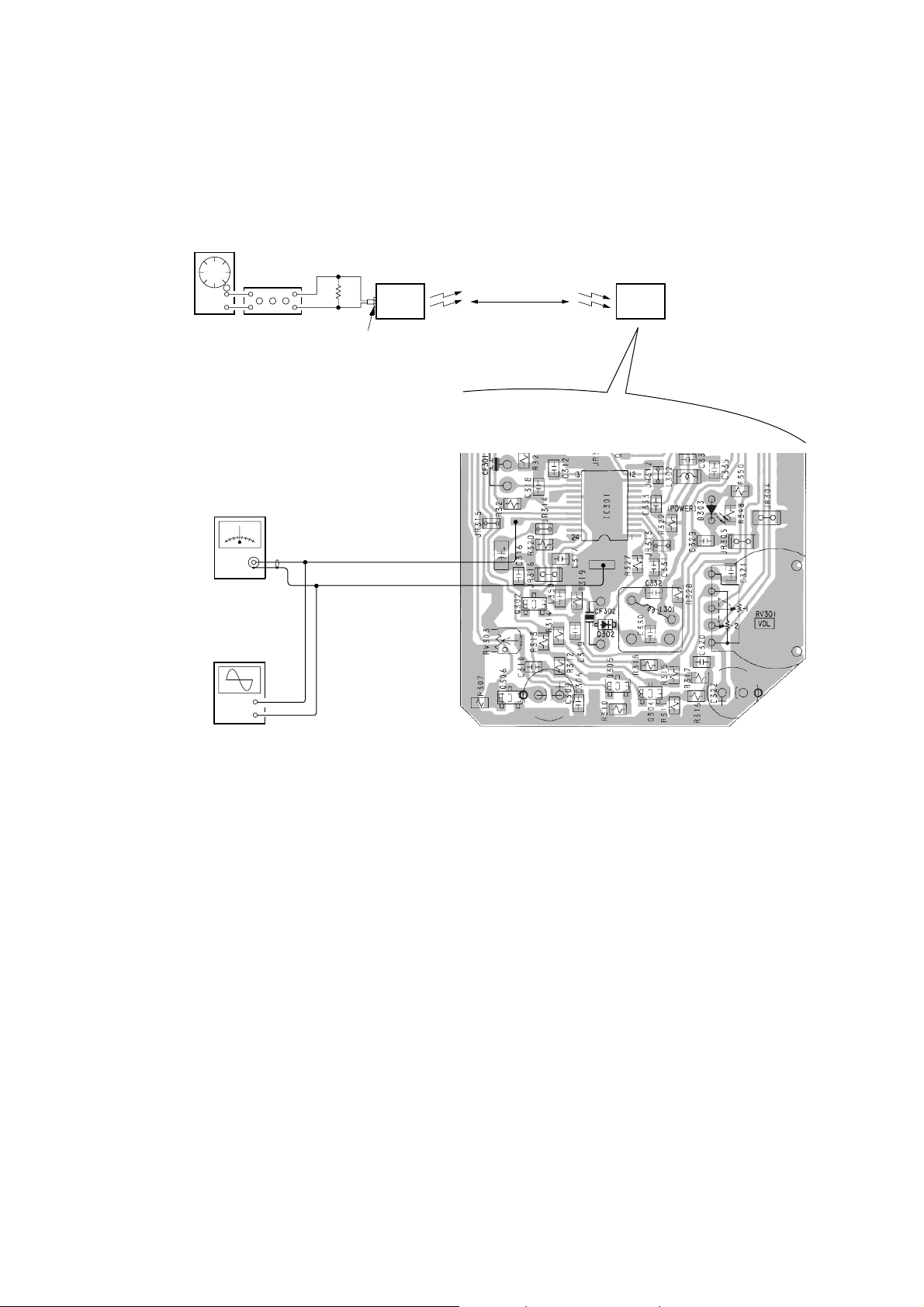
3-1. Receiving Frequency Check and Adjustment
Preparation:
AF OSC
ATT
+
+
–
–
DC voltmeter
oscilloscope
+
–
+
–
600
AUDIO IN (Lch)
1 kHz 316mVrms
TMR-RF930
Transmitter
Ω
MDR-RF93
5 m
Headphones
[RX-BASE board] – Conductor Side –
Procedure:
1. Set the channel of the transmitter to CH2.
2. Turn OFF the noise filter switch on the transmitter.
3. Enter 1 kHz 316 mVrms signal only to the Lch on the transmitter.
4. Place the transmitter away from the headphone (MDR-RF930) more than 5 m.
5. Set the volume control (RV301) on the RX-BASE board to the minimum position.
6. Set the tuning control (RV302) on the RX-BASE board to the center position.
7. Connect a DC voltmeter and an oscilloscope between IC301 pin @¡ and ground on the RX-BASE board.
8. After confirming that demodulated 1 kHz wav eform (about 13 mV) appears on the oscilloscope, check that the DC voltmeter indicates
DC1 V to 1.2 V.
9. If demodulated 1 kHz waveform does not appear on the oscilloscope, or if the voltage is out of the specified value, adjust the air-core
coil (L301) on the RX-BASE board so that the demodulated 1 kHz waveform appears on the oscilloscope, and under this condition,
adjust finely the air-core coil (L301) so that the DC voltmeter indicates DC1.1 V.
10. Finally, check that signals are recei ved when the channel is changed o ver to CH1/CH3 on the transmitter , then when the tunin g control
(RV302) on the RX-BASE board is rotated.
Adjustment Location: RX-BASE board (See page 9.)
– 5 –
 Loading...