

Sony MDRIF-8000 Service manual
MDR-IF8000
SERVICE MANUAL
Ver 1.0 2002.02
• MDR-IF8000 is the component model block one in
MDR-DS8000.
COMPONENT MODEL NAME FOR MDR-DS8000
DIGITAL SURROUND PROCESSOR DP-IF8000
CORDLESS STEREO HEADPHONES MDR-IF8000
US Model
Canadian Model
AEP Model
SPECIFICATIONS
Playback frequency range 12 – 24,000 Hz
Power requirements Rechargeable nickel metal hydride
batteries (supplied or sold separately)
or R6 (size AA) alkaline batteries
Mass Approx.350 g (10 oz)(including the
suppliedrechargable nickel-metal
hydride batteries)
9-873-527-01
2002B0200-1
© 2002.02
CORDLESS STEREO HEADPHONES
Sony Corporation
Parsonal Audio Company
Published by Sony Engineering Corporation
MDR-IF8000
Notes on chip component replacement
• Never reuse a disconnected chip component.
• Notice that the minus side of a tantalum capacitor may be
damaged by heat.
Flexible Circuit Board Repairing
• Keep the temperature of soldering iron around 270˚C during
repairing.
• Do not touch the soldering iron on the same conductor of the
circuit board (within 3 times).
• Be careful not to apply force on the conductor when soldering
or unsoldering.
Repair MDR-IF8000 and DP-IF8000 in a pair.
TABLE OF CONTENTS
1. GENERAL .......................................................................... 2
2. DISASSEMBLY
2-1. Hanger (R) .......................................................................... 3
2-2. VOL Board, RX1 Board, RX2 Board ................................. 3
2-3. PD1 Board........................................................................... 4
2-4. Driver ASSY (SP31) (R-ch Section),
DriverASSY (SP11) (L-ch Section)..................................... 4
2-5. Hanger (L), Headband (R) ASSY, Headband (F) ASSY,
SW Board ............................................................................ 5
3. ELECTRICAL ADJUSTMENTS ................................. 6
4. DIAGRAMS
4-1. Block Diagrams ...................................................................7
4-2. Printed Wiring Board – RX1 Section – ...............................8
4-3. Schematic Diagram – RX1 Section – .................................9
4-4. Printed Wiring Board – RX2 Section – ............................10
4-5. Schematic Diagram – RX2 Section (1/2) – ....................... 11
4-6. Schematic Diagram – RX2 Section (2/2) – ....................... 12
5. EXPLODED VIEWS
5-1. Driver Section.................................................................... 14
5-2. Hanger Section .................................................................. 15
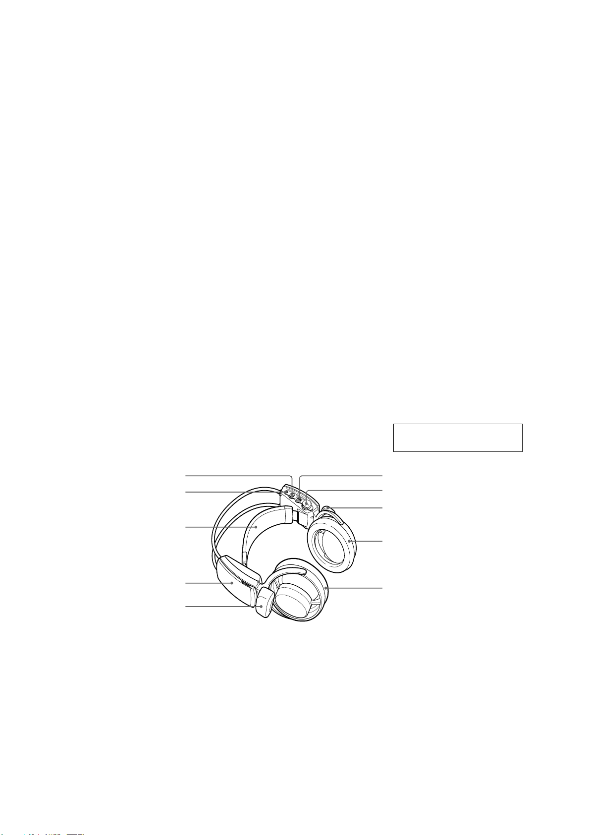
LOCA TING THE CONTROLS
2
SECTION 1
GENERAL
5
4
3
2
1
1 Infrared sensor
There are infrared sensors in two
locations on both sides.
2 Battery case
Press and lift up the lid to open it. This
battery case is for the supplied
rechargeable batteries and R6 (size AA)
alkaline batteries only.
3 Self-adjusting band
The headphones automatically turn on
when you put on the headphones.
4 POWER indicator
By pulling up the self-adjusting band, the
indicator lights red when battery power
is sufficient.
6. ELECTRICAL PARTS LIST ........................................16
This section is extracted from
instruction manual.
6
7
1
8
9
5 RESET button (See page 21 for
details)
Use to reset the location information of
the head tracking function.
6 HEAD TRACKING switch (See page
21 for details)
To activate the head tracking function,
switch it to ON when the output mode of
the processor is set to VIRTUAL (other
than OFF).
7 VOL (Volume) control
Use to adjust the volume.
8 Ear pad (right)
9 Ear pad (left)
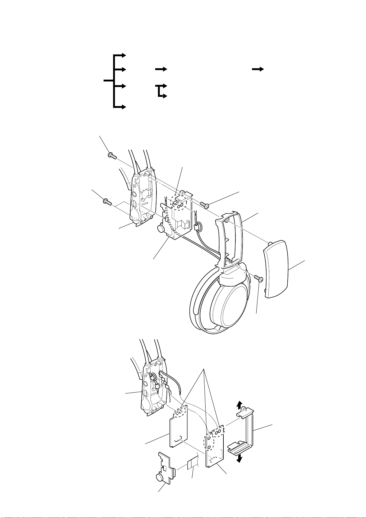
SECTION 2
7
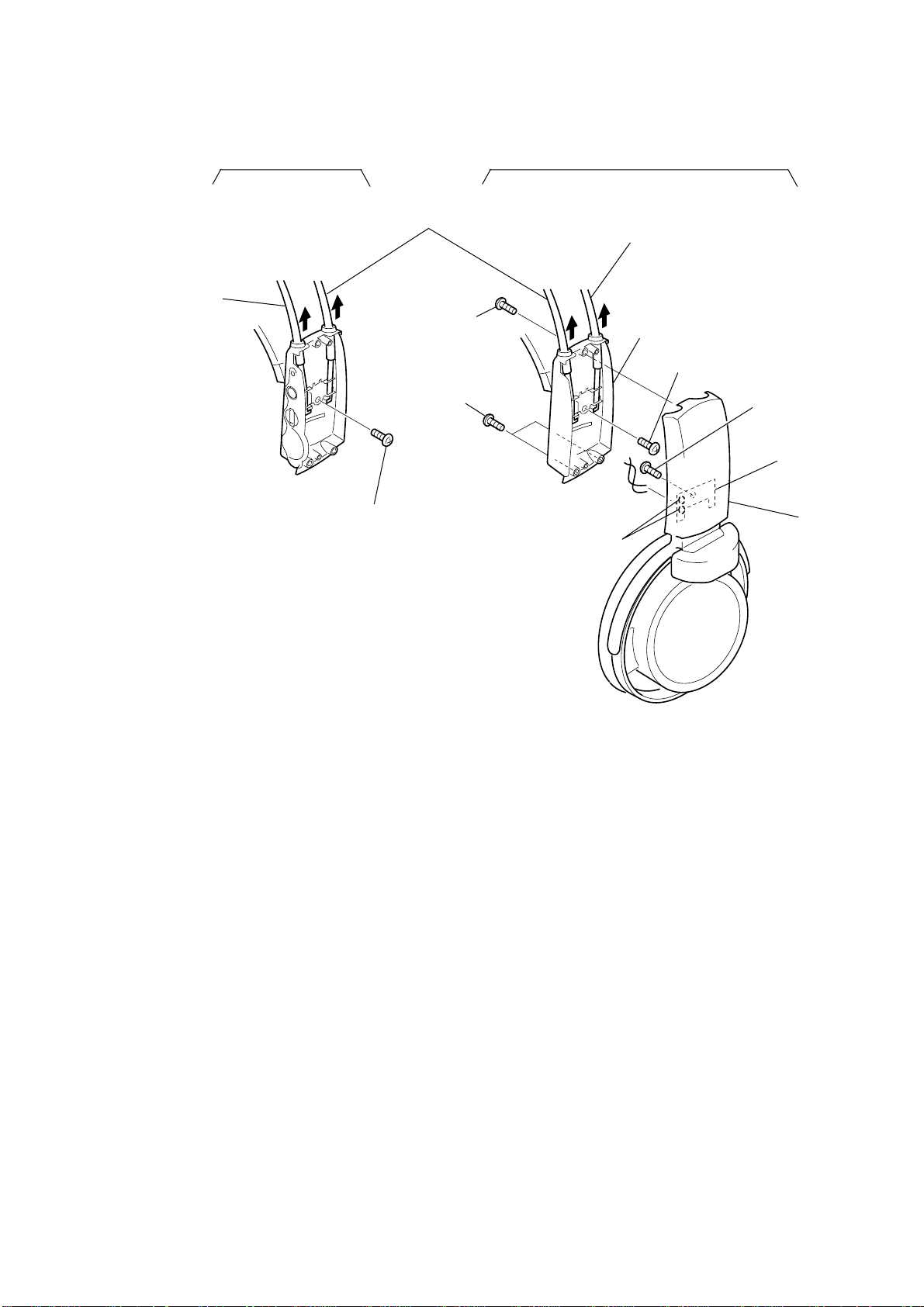
Remove solder (four places)
5
Hanger (R)
3
Hanger lid (R) ASSY
4
Screw (+P 2X8)
Chassis
Lid (R), rear
6
Screw (+P 2X5)
2
Two screws (+P 2X5)
1
Screw (+P 2X8)
DISASSEMBLY
• The equipment can be removed using the following procedure.
Driver ASSY (SP31) (R-CH SECTION)
MDR-IF8000
Hanger (R)
VOL board, RX1 board, RX2 board
Set
Hanger (L)
PD2 board
Head band (R) ASSY, Head band (F) ASSY, SW board
Driver ASSY (SP11) (L-CH SECTION)
Note : Follow the disassembly procedure in the numerical order given.
2-1. HANGER (R)
PD1 board
2-2. VOL BOARD, RX1 BOARD, RX2 BOARD
Lid (R), rear
7
RX2 board
2
VOL board
3
Remove solder (six places)
1
CN502
6
4
5
RX1 board
chassis
3
MDR-IF8000
Y
2-3. PD1 BOARD
• Can remove PD2 board with similar method.
1
Screw (M1.7X5)
4
PD1 board
2
Window, ray catcher
3
Remove solder (two places)
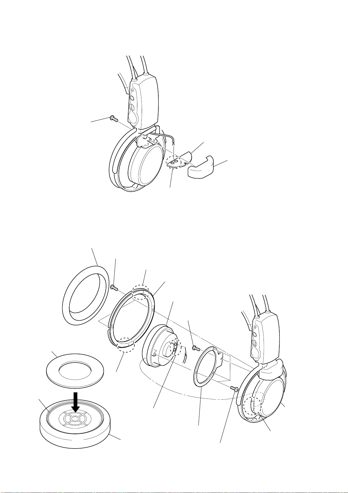
2-4. DRIVER ASSY (SP31) (R-CH SECTION), DRIVER ASSY (SP11) (L-CH SECTION)
• Can remove driver ASSY (SP11) L-CH with similar method.
1
Pad, ear
2
Tow screws (M1.7X5)
3
Claw
4
Ring (ear pad R)
Driver ASSY (SP31)
5
Screw (+P2X5)
Attach the cushion
Cushion
1
Applied the bond in
outside lap with 2mm
width
Bond: Sony bond SC608LV
(7-432-912-52)
4
2
3
Claw
8
Remove solder (two places)
Driver ASSY
Plate, support
7
Three screws (+P2X5)
6
Claw
Frame (R) ASS
2-5. HANGER (L), HEADBAND (R) ASSY, HEAD BAND (F) ASSY, SW BOARD
Headband (F) ASSY
R-CH section
Headband (R) ASSY
Headband (R) ASSY
1
Screw (+P2X4)
0
Remove solder
(two places)
6
Lid (R), rear
7
Screw (+P2X4)
5
Two screws (+P2X5)
4
Screw (+P2X8)
2
9
3
8
qa
Screw (+P2X5)
qs
SW board
Hanger (L)
L-CH section
MDR-IF8000
5
MDR-IF8000
C129
RV121
R104
C108
C105
R137
R136
R107
C145
C101
C136
C134
R130
R128
R103
C131
C130
C132
C102
C115
C104
C103
L153
R140
IC101
C133
C114
C116
L1
L152
C109
C107
R153
1
50
55
60
65
68
40
35
5
10
15
16
20
25
31
SECTION 3
ELECTRICAL ADJUSTMENT
0dB=0.775V
CAUTION:
1. Apply a 2.4 volt DC supply voltage.
2. Use the processor section (DP-IF8000) as a test jig to align the
headphones (MDR-IF8000).
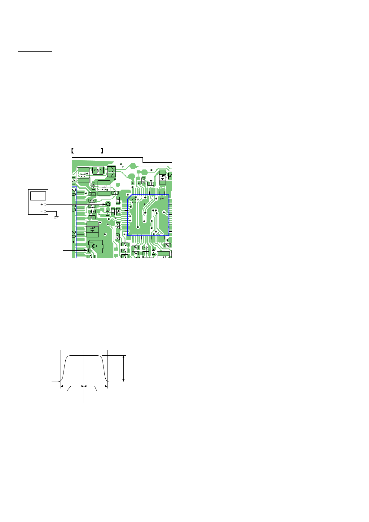
[BPF ADJUSTMENT]
Setup:
1. Set the processor section (DP-IF8000) to test mode, and generate a -10dB signal. (Refer to the DP-IF8000 service manual.)
2. Adjust RV11 (VOLUME) on the VOL board to a minimum.
Connection and adjustment points:
RX2 BOARD (SIDE B)
Spectrum analyzer
RV121
Procedure
1. Connect a spectrum analyzer to the RX2 board as shown in the
above drawing.
2. Adjust the spectrum analyzer output waveform by rotating R V121
so that the center of the waveform is 4.5 MHz with a uniform
balance on both sidebands.
<Reference view of spectrum analyzer waveform after adjustment>
about 25dB
6
about 1.25MHz
4.5MHz
about 1.25MHz
 Loading...