

Sony KV-28FX65B, KV-28FX65E, KV-28FX65U, KV-32FX65B, KV-32FX65E Service manual
...
SERVICE MANUAL
AE-5
CHASSIS
MODEL
KV-28FX65B
KV-28FX65E
KV-28FX65U
COMMANDER DEST CHASSIS NO.
RM-887 FRENCH SCC-Q13J-A
RM-887 ESP SCC-Q14J-A
RM-887 UK SCC-Q15E-A
MODEL
KV-32FX65B
KV-32FX65E
KV-32FX65K
KV-32FX65U
COMMANDER DEST CHASSIS NO.
RM-887 FRENCH SCC-Q13K-A
RM-887 ESP SCC-Q14K-A
RM-887 OIRT SCC-Q15F-A
RM-887 UK SCC-Q16M-A
1

TABLE OF CONTENTS
Section Title Page Section Title Page
Specifications .................... 3
Connectors .................... 5
Self Diagnostic Software .................... 6
1. GENERAL
Tuning your TV .................... 9
Finding your V ideo Channel .................... 9
NexT V iew .................... 9
T eletext .................... 10
Using the TV menu system .................... 11
Specifications .................... 15
Troubleshooting .................... 15
2. DISASSEMBLY
2-1. Rear Cover Removal .................... 16
2-2. Speaker Connector .................... 16
2-3. Chassis Removal .................... 16
2-4. Service Position .................... 17
2-5. D1 Board Removal .................... 17
2-6. J Board Removal .................... 17
2-7. B1 Board Removal .................... 18
2-8. Side Control Removal .................... 18
2-9. F4 Bracket Removal .................... 18
2-10. F4 and H8 Board Removal .................... 18
2-11. Picture Tube Remov al .................... 19
Bottom Plates .................... 20
3. SET-UP ADJUSTMENTS
3-1. Beam Landing .................... 21
3-2. Convergence .................... 22
3-3. Focus, Screen [G2] Adjustment.................... 24
3-4. White Balance .................... 24
5. DIAGRAMS
5-1. Block Diagram (1) .................... 31
Block Diagram (2) .................... 35
Block Diagram (3) .................... 39
Block Diagram (4) .................... 43
5-2. Circuit Board Location .................... 46
5-3. Schematic Diagrams and
Printed Wiring Boards .................... 46
* H7 Board .................... 47
* H8 Board .................... 47
* F4 Board .................... 48
* F1 Board .................... 48
* E Board .................... 49
* M1 Board .................... 53
* D1 Board .................... 56
* D Board .................... 63
* A Board .................... 66
* J Board .................... 75
* C Board .................... 81
* VM Board .................... 83
* B1 Board .................... 85
5-4. Semiconductors .................... 89
5-5. IC Blocks .................... 88
6. EXPLODED VIEWS
6-1. Chassis (28FX65) .................... 92
6-2. Picture Tube (28FX65) .................... 93
6-3. Chassis (32FX65B/E/K) .................... 94
6-4. Picture Tube (32FX65B/E/K) .................... 95
6-5. Chassis (32FX65U) .................... 96
6-6. Picture Tube (32FX65U) .................... 97
4. CIRCUIT ADJUSTMENTS
4-1. Electrical Adjustments .................... 25
4-2. V olume Electrical Adjustments .................... 29
4-3. T est Mode 2 .................... 30
CAUTION
SHORT CIRCUIT THE ANODE OF THE PICTURE TUBE AND THE
ANODE CAP TO THE CARBON PAINTED ON THE CRT, AFTER
REMOVAL OF THE ANODE CAP.
WARNING !!
AN ISOLATION TRANSFORMER MUST BE USED DURING ANY
SERVICE WORK TO AVOID POSSIBLE SHOCK HAZARD DUE TO
LIVE CHASSIS, THE CHASSIS OF THIS RECEIVER IS DIRECTLY
CONNECTED TO THE POWER LINE.
SAFETY-RELATED COMPONENT WARNING !!
COMPONENTS IDENTIFIED BY SHADING AND MARKED
THE SCHEMATIC DIAGRAMS, EXPLODED VIEWS AND IN THE
PARTS LIST ARE CRITICAL FOR SAFE OPERATION. REPLACE
THESE COMPONENTS WITH SONY PARTS WHOSE PART
NUMBERS APPEAR AS SHOWN IN THIS MANUAL OR IN
SUPPLEMENTS PUBLISHED BY SONY.
£
ON
7. ELECTRICAL PARTS LIST .................... 98
ATTENTION
APRES AVOIR DECONNECTE LE CAP DE’LANODE,
COURT-CIRCUITER L’ANODE DU TUBE CATHODIQUE ET CELUI
DE L’ANODE DU CAP AU COUCHE DE CARBONE PEINTE SUR
LE TUBE CATHODIQUE.
ATTENTION !!
AFIN D’EVITER TOUT RISQUE D’ELECTROCUTION PROVENANT
D’UN CHÁSSIS SOUS TENTION, UN TRANSFORMATEUR
D’ISOLEMENT DOIT ETRE UTILISÈ LORS DE TOUT DÈPANNAGE
LE CHÁSSIS DE CE RÈCEPTEUR EST DIRECTMENT RACCORDÈ
Á L’ALIMENTATION SECTEUR.
ATTENTION AUX COMPOSANTS RELATIFS Á
LES COMPOSANTS IDENTIFIÈS PAR UNE TRAME ET PAR UNE
MARQUE
EXPLOSÈES ET LES LISTES DE PIECES SONT D’UNE IMPOR-
TANCE CRITIQUE POUR LA SÈCURITÈ DU FONCTIONNEMENT,
NE LES REMPLACER QUE PAR DES COMPSANTS SONY DONT LE
NUMÈRO DE PIÈCE EST INDIQUÈ DANS LE PRÈSENT MANUEL
OU DANS DES SUPPLÈMENTS PUBLIÈS PAR SONY.
£
SUR LES SCHÈMAS DE PRINCIPE, LES VUES
LA SECURITÈ!!
2
LEDOMMETI metsySnoisiveleT metsySoeretS egarevoClennahC metsySroloC
hcnerFI,L,K/D,H/G/B
hsinapSK/D,H/G/B
TRIOK/D,H/G/B
KUIoeretSMACIN
ledoM B56XF82-VK E56XF82-VK U56XF82-VK
ledoM B56XF23-VK E56XF23-VK U56XF23-VK K56XF23-VK
oeretS
oeretS
oeretS
noitpmusnoCrewoPW621W621W621
noitpmusnoCrewoPW221W221W221W221
MACIN/NAMREG
MACIN/NAMREG
MACIN/NAMREG
21R-10R,21E-20E:FHV
96R-12R,96E-12E:FHU
Q-B,02S-10S:VTELBAC
14S-12S:REPYH
21R-10R,21E-20E:FHV
96R-12R,96E-12E:FHU
02S-1S,50S-10S:VTELBAC
14S-12S:REPYH
21R-10R,21E-20E:FHV
96R-12R,96E-12E:FHU
02S-1S,50S-10S:VTELBAC
14S-12S:REPYH
96B-12B:FHU
MACES,LAP
85.3CSTN,34.4CSTN
)NIOEDIV(
MACES,LAP
85.3CSTN,34.4CSTN
)NIOEDIV(
MACES,LAP
85.3CSTN,34.4CSTN
)NIOEDIV(
MACES,LAP
85.3CSTN,34.4CSTN
)NIOEDIV(
ediWnortinirTDF
ebuTerutciP
]RAER[slanimreTtuptuO/tupnI
rotcennocoruEnip-12:1
)dradnatsCELENEC(
rotcennocoruEnip-12:2
rotcennocoruEnip-12:3
srotcennoCACRslangiSoiduAroftuptuoelbairaVserutaeFrehtO
kcajenohpdaeHkcajinimoerets stnemeriuqerrewoP
stupnioiduAskcajonohp snoisnemiD)d/h/w(mm32x54x012xorppA
stupnioediVskcajonohp thgieW)yrettabgnidulcniton(g59xorppA
tupnioediVSNIDnip4
)yllanogaid
)yllanogaid
.BGRrofstupnI
.slangis
)elbatceles(
)tuorotinom(
]TNORF[slanimreTtuptuO/tupnI metsyslortnocetomeR
)sehcni82(mc17xorppA
derusaemerutcipmc66xorppA(
)sehcni23(mc28xorppA
derusaemerutcipmc67xorppA(
noitcelfedeerged011
.slangisoediVdnaoiduArofstupnI
oiduAdnaoediVVTfostuptuO
.slangisoediVdnaoiduArofstupnI
.oediVSrofstupnI
.slangisoiduAdnaoediVVTfostuptuO
.slangisoediVdnaoiduArofstupnI
.oediVSrofstupnI
slangisoiduAdnaoediVrofstuptuO
tuptuodnuoS
refoowbuS
stnemeriuqeRrewoPCAV042-022
snoisnemiD
thgieW
seirosseccAdeilppuS
cdV3
)AAezis(6R
.ecitontuohtiwegnahcottcejbuserasnoitacificepsdnangiseD
rekaepstfeLdnathgiR
)rewoPcisuM(W02x2
)SMR(W01x2
)SMR(W51x1)rewoPcisuM(W03x1
mm225x815x697xorppA"82
mm265x765x388xorppA"23
gk0.84xorppA"82
gk0.46xorppA"23
)1(rednammoCetomeR788-MR
)2(yrettab6RdetangisedCEI
esioN,retliFbmoClatigiD,weiVTxeN
0002,resilauqEcihparG,noitcudeR
.yromeMtxeTegaP
lortnocderarfnI
noitangisedCEIseirettab2
3
emaNledoM
metI
B56XF82-VK
B56XF23-VK
E56XF82-VK
U56XF82-VK
K56XF23-VK
E56XF23-VK
U56XF23-VK
bmoClaPFFOFFOFFOFFO
PIPFFOFFOFFOFFO
ytiroirPBGRNONONONO
xoBrefooWNONONONO
1tracSNONONONO
2tracSNONONONO
3tracSNONONONO
)4(nitnorFNONONONO
rotcejorPFFOFFOFFOFFO
edom9:61niBKANONONONO
G/BmroNNONOFFONO
ImroNNOFFONOFFO
K/DmroNNONOFFONO
SUAmroNFFOFFOFFOFFO
LmroNNOFFOFFOFFO
TASmroNFFOFFOFFOFFO
MmroNFFOFFOFFOFFO
txeteleTNONONONO
oeretSmaciNNONONONO
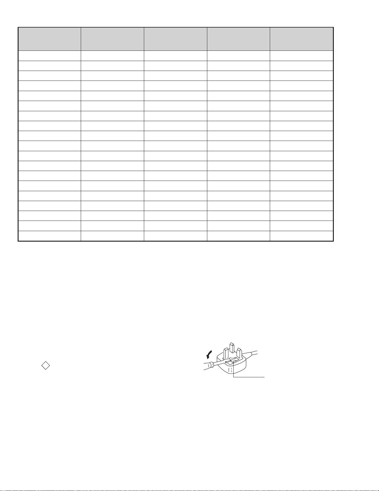
WARNING (UK Models only)
The flexible mains lead is supplied connected to a B.S. 1363 fused plug
having a fuse of 13 AMP rating. Should the fuse need to be replaced,
use a 13 AMP FUSE approved by ASTA to BS 1362, ie one that
carries the
IF THE PLUG SUPPLIED WITH THIS APPLIANCE IS NOT SUITABLE
FOR THE OUTLET SOCKETS IN YOUR HOME, IT SHOULD BE CUT
OFF AND AN APPROPRIATE PLUG FITTED. THE PLUG SEVERED
FROM THE MAINS LEAD MUST BE DESTROYED AS A PLUG WITH
BARED WIRES IS DANGEROUS IF ENGAGED IN A LIVE SOCKET.
When an alternative type of plug is used, it should be fitted with a
13 AMP FUSE, otherwise the circuit should be protected by a 13 AMP
FUSE at the distribution board.
ASA
T
mark.
How to replace the fuse.
Open the fuse compartment with
a screwdriver blade and replace
the fuse.
FUSE
4
21 pin connector
21
19
17
15
13
11
9
7
5
3
1
20
18
16
14
12
10
8
6
4
2
Pin No 1 2 3 Signal Signal level
1 Audio output B
2
3
4 Ground (audio)
5 Ground (blue)
6 Audio input A
7 Blue input 0.7 +/- 3dB, 75 ohms positive
8 Function select
9 Ground (gre en)
10 Open
11 Green Green signal : 0.7 +/- 3dB, 75 ohms,
12 Open
13 Ground (red)
14 Ground (blanking)
15
_ (S signal Chroma
16 Blanking input
17 Ground (video
18 Ground (video
19 Video output 1V +/- 3dB, 75ohms, positive sync 0.3V
20
_ Video input
21 Common ground
(right)
Audio output B
(right)
Audio output A
(left)
(left)
(AV control)
_ _ Red input 0.7 +/- 3dB, 75 ohms, positive
input)
(Ys signal)
output)
input)
_ _ Video input 1V +/- 3dB, 75ohms, positive sync 0.3V
Y (S signal)
(plug, shield)
Standard level : 0.5V rms
Output impedence : Less than 1kohm*
Standard level : 0.5V rms
Output impedence : More than 10kohm*
Standard level : 0.5V rms
Output impedence : Less than 1kohm*
Standard level : 0.5V rms
Output impedence : More than 10kohm*
High state (9.5-12V) : Part mode
Low state (0-2V) : TV mode
Input impedence : More than 10K ohms
Input capacitance : Less than 2nF
positive
0.3 +/- 3dB, 75 ohms, positive
High state (1-3V) Low state (0-0.4V)
Input impedence : 75 ohms
(-3+10dB)
(-3+10dB)
1V +/- 3dB, 75ohms, positive sync 0.3V
(-3+10dB)
Connected Not Connected (open) * at 20Hz - 20kHz
Rear Connection Panel Front Connection Panel
p
- +
niP
oN
S-Video
socket
4
s
4
4
MONO
L/G/S/I
4
R/D/D/D
1dnuorG2dnuorG3tupni)langisS(Y,mho57Bd3-/+V1
4tupni)langisS(CBd3-/+V3.0
5
langiS leveLlangiS
noitarugifnocniptekcosoediVS
V3.0.cnySevitisop
Bd01+3-
evitisop,mho57
.cnyS
AE-5 SELF DIAGNOSTIC SOFTWARE
The identification of errors within the AE-5 chassis is triggered in one of two ways :- 1: Busy or 2: Device f ailure to respond to IIC. In the e vent of
one of these situations arising the software will first try to release the bus if busy (Failure to do so will report with a continuous flashing LED) and
then communicate with each device in turn to establish if a device is faulty . If a de vice is found to be faulty the relev ant de vice number will be
displayed through the LED (Series of flashes which must be counted) See table 1., non fatal errors are reported using this method.
metIcitsongaiD
noitpircseD
nonruttonseodrewoPthgiltonseoD
)PCO(tnerrucrevOB+semit2
deppotsnoitcelfeDlacitreVsemit4
ybdnatSsemitfooN
sehsalFDEL
.tiucricneposiesuF
egasseMrorrE
rorreoN00
devreseR10
)noitcetorPtnerruCrevO(PCO20
)noitcetorPegatloVrevO(PVO30
noitcetorPlacitreV40
)26TTelbasid
noitcetorPlatnoziroH60
noitcetorPrekaepS70
rorre0subC2I80
redoceD-txeT-eleTB-M90
MVN,23C42TSB-M01
redoceDruoloCniaM,0239ADTB-J11
xoBerutaeFB-2B/1B21
retrevnoC-A/DB-1B31
dnekcaBB-E41
rossecorPdnuoS,D0143PSMB-J51
ediWotuA,7502DXCB-J61
MARlanretxE71
esuacelbaborP
noitacoL
.nideggulptonsidrocrewoP
)draoBD(.detrohssi)4086/3086Q(TUO.H
)draoBD(.detrohssiCIrewoP4066CI
)draoBD(detrohssi0076CI
16TTelbane,s'03retfastratskcehc(BKAelbatsnU
smotpmySdetceteD
noemoctonseodrewoP
VTehtotdeilppussirewopoN
ytluafsiylppusrewopCA
)draoBD(.detrohssi)6086Q(TEFytiraeniL
)draoBD(nepo5386RdeilppustonsiV51+
)draoBD(nepo4386RdeilppustonsiV51-
DEL
sehsalF
50
noemoctonseodrewoP
detrohssahenilrewopnodaoL
deppotssaheslupnoitcelfedlacitreV
detrohssahenilrewoP
Flash Timing Example : e.g. error number 3
StBy LED
ON ON ON
OFF
6
OFF

Error Detection Monitor
Device acknowledge is used to check IIC errors. Device ackno wledge is checked by sending an IIC start sequence during CRT power on. Each
device is checked three times, if there is no acknowledge after each attempt, it will be regarded as an error .
There are three steps to check for errors.
1. IIC line 0
If all devices except the NVM have errors, IIC line 0 error is displayed.
2. Board check
If all devices mounted on one board have errors, board error is displayed.
3. Each device check
If IIC line error and board error are not detected then the device with the error is displayed.
The detected errors can be displayed as follows :
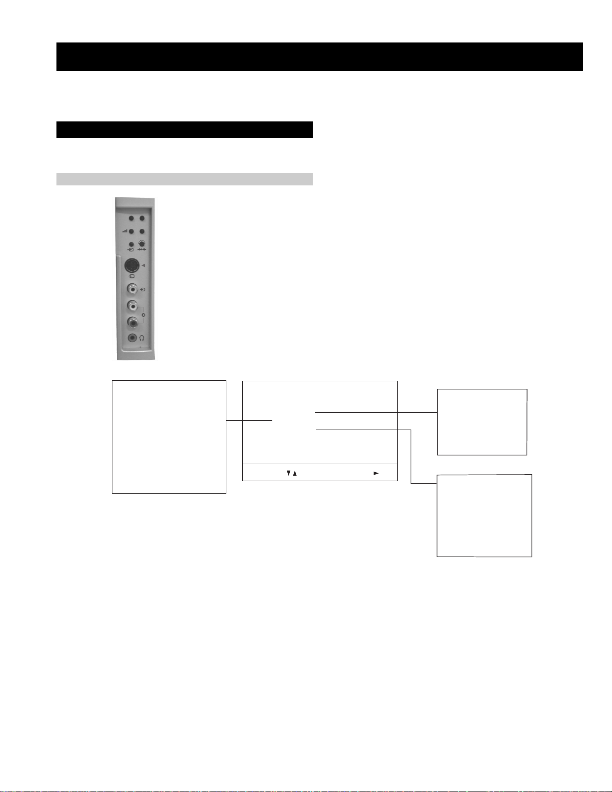
1. Error Monitor Menu.
2. Error Reader.
1. Error Monitor Menu
Error Display Mode is entered by the following sequence of commands Standby -> Information -> Digit 5 -> Volume Down -> TV
ERROR MONITOR
1. IGNORE ERRORS OFF ON OFF
Operating Time : 000075 h 15 min
Stored Errors :
1. D1 - B CXA1875 or MB88141
2. No Error Occured
3. No Error Occured
4. No Error Occured
5. No Error Occured
Current Error :
Start Error Sequence
Last menu Enter Item
7

2. Error Reader Display
The error reader display is connected to the service connector to read actual error codes. The part number for the error reader display is
S-188-900-10. Once an error has been detected it will then be displayed on the two digit error reader. The erro rs displayed refer to the following
table.
edoCrorrE egasseMrorrE
h000derruccororreoN
h1000CII,rorresuB
h2001CII,rorresuB
h001draoB-A
h101rednapxEtroP,5781AXCB-A
h201renuTniaM,6231UTB-A
h301renuTbuS,0531UTB-A
h002draoB-1B
h102,0829ADS.B-1BxoBerutaeF,456C38PB-1B
h202B-1B
h003 draoB-2B
h103CISEB,7794AAS.B-2B
h203yromeMdleiF,X594AAS.B-2B
h004draoB-3B
h104X-DIM.B-3B
h204amaronaP.B-3B
h304CRD.B-3B
h404retsooBerutciP.B-KB
h005draoB-1D
h105rotrevnoCcimanyD,0708AXCB-1D
h205rednapxEtroP,5781AXCB-1D
h006draoB-E
h106dnekcaB,0012DXCB-E
h007draoB-J
h107ediWotuA,7502DXCB-J
h207PIP,8829ADSB-J
h307redoceDruoloCbuSB-J
h407redoceDruoloCniaMB-J
h507dnuoS-buS,5781AXCB-J
h607reifilpmA-PH,9037ADTB-J
h707hctiwSoiduA,TD2246AETB-J
h807rossecorPdnuoS,D0143PSMB-J
h907PSDdnuoS,F7339CTB-J
hA07hctiwSVA,96X12AXCB-J
h008draoB-M
h108MVN,23C42TSB-M
0829ADS.B-1BxoBerutaeF,456C38P
rotrevnoCA/D
rotrevnoCA/D,
8
SECTION 1 GENERAL
Tue 07. 04 .98
10:35 - 12:45
TXT TPS / RINGIER
10:20 - 12:00
10:45 - 10:50
11:00 - 11:20
11:45 - 12:50
Operation
NexTView*
SWISS
Werner - Beinhart
Pro 7
Flui grüsst den Rest der Welt
Kabel 1
Star Wars
Super RTL
12
7
8
9
Tue
Thu
12:38
Index
Wed
full list of selection
personal selection
news broadcasts
movies
07 Tue
a future programme brings you to the long info menu.
NexTView is an electronic programme guide with up to 1 week* of p rogramme info rmation on those chan nels includ ed in
the selected provider.
*If the data exceeds the memory of NexTView, you will get information on less than 7 days.
* depending on availability of service
When looking for information you can search by theme (sports, art etc.), date or time (e.g. broadcasts between 8 and 9 p.m.).
When you’ve found a programme you can go directly to this programme, use the timer to remind you of it or preset your VCR
with Smartlink.
The NexTView provider is responsible for the contents of the guide. The TV set is responsible for the presentation , that is
the menu structure and the navigation, if there is none from the provider. If there is a navigation from the provider the basic
operation with the joystick is the same as described in the Sony navigation.
At first you need to select a channel providing a NexTView service. In this case the indication “NexTView” is displayed
as soon as all data is available. When you later change the channel you can still select this NexTView service.
Operation using the Sony navigation
• moving up or downwards within a column: Use v or V.
• going to the left columns time and date: Use b.
• going to the right column icons: Use B.
• Confirming a selection: Press OK.
(a) while in the columns date, time or icon (themes), the programme list changes according to the selection.
1. Press to switch NexTView on and off.
2. Use the joystick buttons as follows
(b) while in the programme list, confirming a running broadcast brings you dir ectly to the TV programme or con firming
sports
10
Once upon a time in the West
Euronews
Fri
entertainment
International News
RTL Plus
11
12
Sat
children
return to last menu
Fantasy film, USA, 1996
13
Sun
Mon
8
5
3
6
9
2
8
5
0
OK
4
7
1
Italy
France
Language country
Dansk
Čeština
Deutsch
Language
Country
English
Italiano
Español
Français
Select Language: Confirm:
Language country
English
Language
Country
Ireland
Greece
Hungary
Germany
Great Britain
Select Country: Confirm:
:
:
:
:
PROG CH LABEL
Programme Sorting
TV 5
PRO 7
EU-SP
SWF
RTL
SAT
MDR
DDI
C03
C05
C07
C08
C09
C11
C12
C13
1 2 3 4 5 6 7 8 91011
C03 TV 5
DSF
RTL 2
KAB 1
TV 5
PRO 7
EU-SP
SWF
RTL
SAT
MDR
DDI
DSF
RTL 2
PROG CH LABEL
Programme Sorting
C03
C05
C07
C08
C09
C11
C12
C13
1 2 3 4 5 6 7 8 91011
KAB 1
C14
C15
C16
Select Position: Move: OK
C14
C15
C16
Select Prog: Confir m:
The operating instructions mentioned here are partial abstracts from the ‘Operating
Instruction Manual’. The page numbers of the ‘Operating Instruction Manual’ remain
as in the manual.
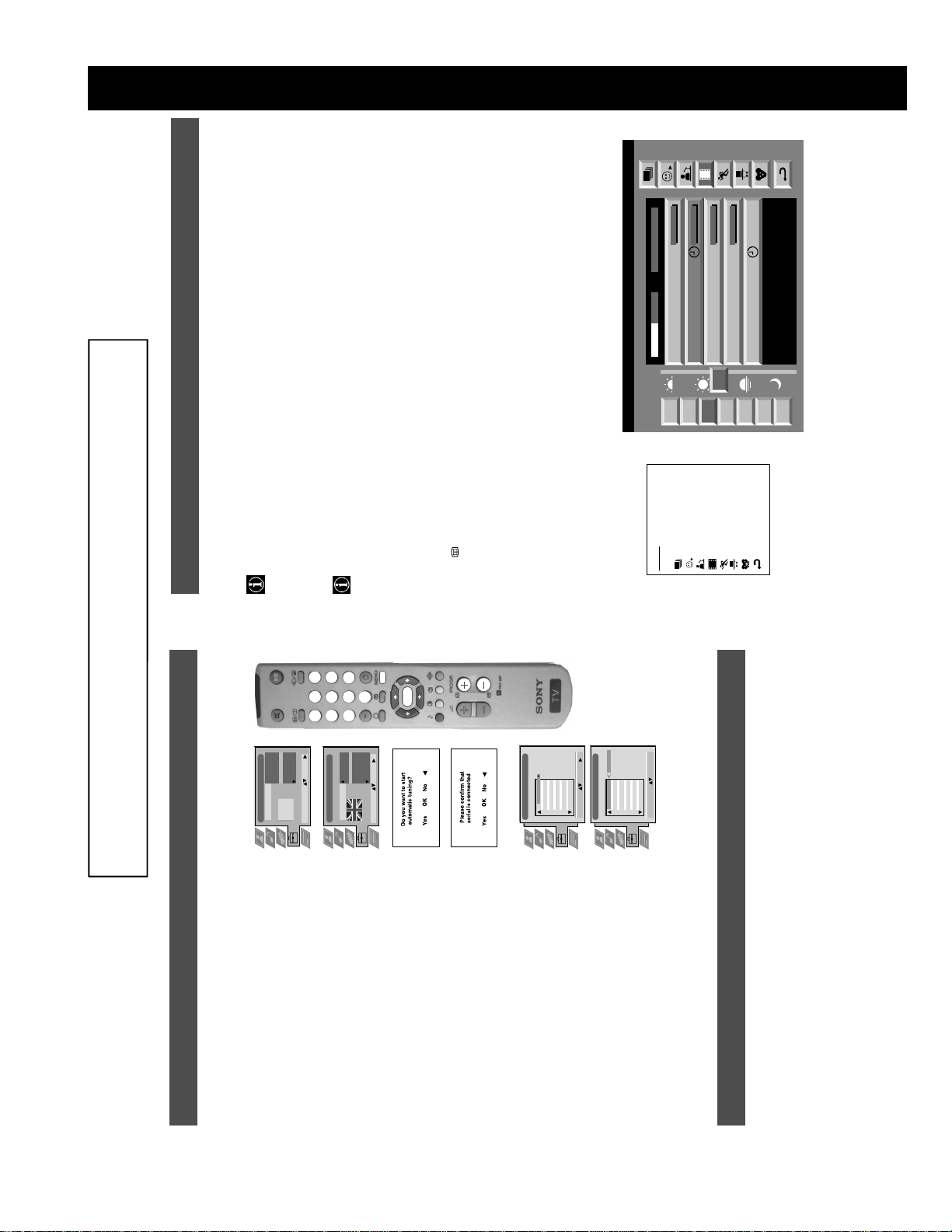
Installation
5. Tuning your TV
3. Press v or V to select the country in which you wish to operate
4. The ‘autotune’ menu appears on the TV screen in your selected
Before you tune your TV, you will be asked to set your language and country.
language. Press the OK button to confirm.
1. The Language/Country menu appears on the TV screen with the
2. Press the v or V buttons on the remote control to select your
button to confirm. The TV starts to automatically search and store
5. Ensure the aerial is connected as instructed, then press the OK
please be patient and do not press any buttons.
all available channels for you. This may take a few minutes -
Sorting’ menu appears on the TV screen enabling you to change
the order of the channels on your TV. If you wish to change the
channel order, press the v or V buttons to select the channel you
want to move, then press B. Press the v or V buttons to select the
new programme number position for your selected channel then
press the OK button to confirm. The selected channel now moves
to its new programme position and the other channels move
accordingly. Repeat this procedure if you wish to sort the order of
6. Once the TV has tuned all available channels the ‘Programme
other channels on your TV.
7. Press the MENU button to remove the menu from the TV screen.
channels.
8. Press the PROGR+/- or the numbered buttons to view the TV
Note: If you would like to stop the autotune process at any stage,
6. Finding your video channel
If you have connected a VCR to your TV, you now need to find your video channel. Please refer to the ‘Connecting the TV’
section of this manual on page 3.
word ‘English’ highlighted.
press the OK button.
chosen language then press the OK button to confirm.
‘OFF’ if you do not want your channels stored in a given channel
the TV then press the OK button to confirm your choice. Select
sequence starting from programme position 1.
section of this instruction manual.
1. Press the PROGR+/- buttons on the TV remote control until your video picture appears on the TV screen.
Note: If you wish to move your video channel to a different programme position, refer to the ‘Re-arranging the TV channels’
9
25
153
101
25
153
101
98
m
m
98
m
TELETEXT
Index
Programme
News
Sport
Weather
Most TV channels broadcast information via Teletext. The index page of the teletext service (usually page 100) gi ves you
information on how to use the service. Please use a TV channel with a st rong signal, otherwise there may be Teletext errors.
T eletext
Operation
Switching Teletext on and off
1. Select the TV channel which carries the teletext service you want to view.
2. Press the button once to get Teletext only.
3. Press twice for Mix mode.
4. Press a third time to switch off Teletext.
Selecting a Teletext page
Input three digits for the page number using the numbered buttons on the remote control. If
you make a mistake, type in any three digits then re-enter the correct page number.
TELETEXT
Index
Programme
News
Sport
Using Other Teletext Functions
Weather
Selecting the next or preceding page
Press the or buttons on the remote control to select the previous or next page.
216-02
Selecting a sub page
A teletext page may consist of several sub pages. In this case an information line is displayed,
showing the number of subpages. Select the sub page by pressing v or V.
To freeze a Teletext page
Press the button to freeze the page. Press again to cancel the freeze.
Revealing concealed information
Press the button to reveal information. Press again to conceal the information.
01 03 04 05 06 07 0802
several page numbers on it (eg the index page).
Using the feature ‘Page Catching’
page is displayed after some seconds.
1. Press the numbered buttons on the remote control to select a teletext page which has
2. Press the OK button.
Using colour buttons to access pages (Fastext)
(only available if the TV station broadcasts Fastext signals)
When the colour coded menu appears at the bottom of a page, press a coloured b utton on the
remote control (green, red, yellow or blue) to access the corresponding page.
3. Press v or V to select the desired page number then press the OK button. The requested
10
9
On
SP
VCR1
Speed
VCR Setup
VPS/PDC
Tue 07. 04 .98
SP
On
VCR1
SWISS TXT TPS / RINGIER nexTView
Address Mapping
The position of the addresses in the
OSDA is shown in the following diagram.
First nextTView/EPG-Providers in Europe
When you select there will be no personal pre-selection. lets you make your own ind ividual selectio n of theme s,
limiting the search to the marked ones.
The menu Individual Settings is displayed.
NexTView*
Operation
Individual Setting
Repeat step 2 for all the items you wish to have in your list.
1. Select using v or V. Push B to enter.
2. Select the item you wish to mark using v or V. Confirm by pressing OK.
3. When finished with the list, select using B and press OK.
Using the ‘Long Info’ menu
The long info menu is displayed.
1. Select a future programme in the column programme list using v or V. Press OK.
The position values of the DPW are set
07 Tue
12:38
to '0'.
If other values are set, the complete
combination will be scrolled.
Example:
This channel has been set for a timer
Speed
Timer Prog
VPS/PDC
if the DPWC is set to '63', the char-
You may wish to record the selected programme with your VCR.
With this setting on, you have the guaranteed recording of the whole broadcast
should there be a change in the TV programme. This only works if the selected
This information is transferred to the VCR connected to your set.
(only with Smartlink VCRs)
2. Select using b and press OK.
Setting up ypur VCR
channel broadcasts a VPS/PDC signal.
3. Select VPS/PDC by pushing b repeatedly.
Select between standardplay (SP) or longplay (LP) mode.With longplay you can
• Select On or Off using OK.
record twice as much on a videotape. The picture quality, however, may suffer.
4. Select Speed using V.
• Select SP or LP using OK.
Select which of the connected Smartlink VCRs you wish to programme.
• Select VCR 1 or 2 using OK.
5. Select VCR Setup using V.
You are back in the last menu.
6. Select using B. Press OK.
10
Personal
On
On
Live
Normal
Personal
Movie
On
Off
On
Off
Cool
Warm
Normal
Operation
Using the TV menu system
The TV consists of a menu system which is based on a series of user friendly on -s creen d isplays and men us . Th ese display s will
Picture Adjustment
Picture Mode
Contrast
Brightness
Colour
Sharpness
ResetAINoise Reduction
Colour Tone
Select: Enter:
Picture Mode
Contrast
Noise Reduction
AI
Colour Tone
broadcasting signal.
Personal (for individual settings)
v Movie (for movie broadcasts)
B to enter either the ‘Picture Adjustment’ menu or the ‘Audio Adjustment’ menu.
help you get the most from your TV, helping you to change picture and sound settings, to alter the size of the TV picture and to
rearrange the TV channels etc.
Adjusting the picture and sound
The picture and sound are preset at the factory. You can however adjust them to suit your own taste.
1. Press the MENU button on the remote control to display the menu on the TV screen.
confirm. For a description of the menu items and their effects, see the table below.
2. Press the v or V buttons to select for picture settings or for sound settings then press
3. Press the v or V buttons to select the item on the screen you wish to adjust then press B to
4. Press the v, V, B or b buttons to adjust your selected item.
5. As soon as you have adjusted the item, press the OK button to store the new setting.
Picture Control
Item Effect/Operation
Picture Mode V Live (for live broadcasts)
Contrast Less bB More
Brightness* Darker bB Brighter
Colour* Less bB More
Hue** Reddish bB Greenish
Sharpness* Softer bB Sharper
*Only available if ’Personal’ is selected in ‘Picture Mode’
6. Repeat steps 3-5 if you wish to adjust any of the other items.
7. Press the MENU button to remove the menu from the TV screen.
**Only available for NTSC colour signal (eg. US video tapes)
Reset Resets picture to the factory preset levels
AI V On: Automatic optimization of contrast level
(Artificial Intelligence) according to the TV signal.
v Off: Normal.
Noise Reduction V On: Reduces picture noise in case of a weak
v Off: No noise reduction.
Colour Tone V Warm: Gives a warm tint to the picture.
Normal: Normal.
v Cool: Gives a cool tint to the picture.
12
11
- - : - -– – –
Time Page
PAGE TIME
Teletext
Top / Bottom / Full
Text Clear
Reveal
Time Page
Select: Enter Menu:
Page Overview
Top: Bottom: Full: OK
menu on the TV screen.
Teletext
Operation
Using the Teletext menu
sub menu.
1. With Teletext switched on, press the MENU button on the remote control to display the
2. Press v or V to select your chosen item on the screen then press B to display the relevant
3. To remove the Teletext menu from the screen, press the MENU button.
Top/Bottom/Full
The Top/Bottom/Full sub menu allows you to enlarge different sections of the Teletext page.
Press v to enlarge the upp er half of the screen, Press V to enlarge the lower half. Press the OK
button to restore the page to normal size. Press b to return to the Teletext menu screen.
Text Clear
Text Clear is a function that displays a TV channel while a Teletext page is being searched for.
symbol will appear in the top left hand corner of the screen.
1. Press the button on the remote control to select full screen text.
2. Press the MENU button to display the ‘Teletext’ menu.
3. Press v or V to highlight ‘Text Clear’ and press B to select.
4. The current TV channel is displayed. Once the text page has been found a blue
5. Press the button on the remote control to view the page.
Reveal
Some Teletext pages contain hidden information (eg for a quiz), which can be revealed.
displayed on the screen.
1. In text mode press the MENU button on the remote control to access the ‘Teletext’ menu.
2. Press v or V to highlight ‘Reveal’ and press B to select. The hidden information is
Time Page*
*depending on availability of service.
menu.
is displayed.
1. In Text mode press the MENU button on the remote control to access the ‘Teletext’
2. Press v or V to highlight ‘Time Page’ and press B to select. The ‘Time Page’ sub menu
Time Page allows a time-coded Teletext page (such as an alarm page), to be display ed at a set
time.
3. Enter the desired page number using the numbered buttons on the remote control.
Select Page: 0-9 Next:
displayed in the top left hand corner of the screen. At the requested time the desired p age
is displayed.
Page Overview*
*only available if TOP-Text is transmitted by the TV station.
In this menu the TOP-Text pages are divided into two columns, the first column showing
‘blocks’ of pages and the second showing ‘groups’ of pages.
1. Press b or B to select the first or second column.
4. Enter the desired time using the remote control.
5. Press OK to confirm the settings. The TV will exit Teletext mode and the time will be
2. Press v or V to select the relevant ‘group’ or ‘block’ of pages.
3. Press the OK button to display the chosen pages.
11
TV
Off
On
Off
Off
Off
Off
On
On
10 min
Off
On
TV
AV 2
AV 3
AV 4
AV 1
Features
1. Press the MENU button on the remote control to display the menu on the TV screen.
Using the Features menu
2. Press the v or V buttons to select for the ‘Features’ menu then press B to enter the ‘Features’
Using the TV menu system:
Format Correction
Sleep Timer
Auto Format
menu.
3. Press the v or V buttons to select the desired menu item then press B to confirm. For a description
Parental Lock
of the menu items and their effects, see the table below.
AV 2 Output
4. Press the v, V, B or b buttons to select the desired setting.
Select: Enter:
Auto Format
Format Correction
dark areas on the TV picture (as shown below):
5. Press the OK button to confirm your choice of setting.
6. Repeat steps 3-5 if you wish to select any of the other items.
7. Press the MENU button to remove the menu from the TV screen.
Auto Format* V Off:Size of picture does not automatically adjust.
Item Effect/Operation
(*only if Auto Format is v On: Smart mode is selected automatically for 4:3/14:9 broadcasts.
Format Correction* V Off: 4:3/14:9 is selected.
*only for aerial signal v On:The TV will automatically adjust the picture size to eliminate any
Sleep Timer
standby mode.
V Off
set to ‘On’)
Sleep Timer You can select a time after which the TV switches itself into
v 90 min
Parental Look
v On: This feature disables the buttons on the TV when the set is in standby
Parental Lock V Off: No parental lock.
AV 2 Output
mode. It is only possible to switch the set back on by pressing a
button on the remote control.
AV1 audio/video signal from scart 1.
AV2 audio/video signal from scart 2.
AV3 audio/video signal from scart 3.
v AV4 audio/video signal from connectors on front of the TV.
AV2 Output V TV audio/video signal from the aerial .
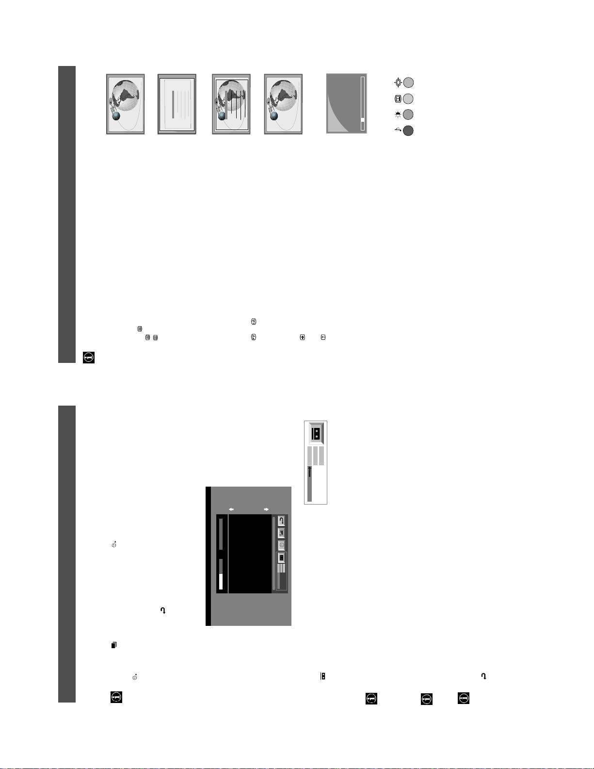
Wide
This feature allows you to change the size of the TV picture.
Changing the screen size
Zoom
Press the button on the remote control repeatedly or use the v or V buttons to select one of the
following formats then press the OK button to confirm your selection:
14:9
Wide for 16:9 broadcasts.
Zoom widescreen format for letterbox movies.
14:9 compromise between 4:3 and 16:9 picture size.
4:3 conventional 4:3 picture size, full picture information.
4:3
Smart imitation of wide screen effect for 4:3 broadcasts.
In Smart, Zoom and 14:9 modes parts of the top and bottom of the screen are cut off. Press v or V to adjust
the position of the image on screen (eg to read subtitles) then press the OK button to confirm.
Smart
14
B
Off
On
Off
Off
Off
Off
Off
Jazz
Rock
Vocal
Personal
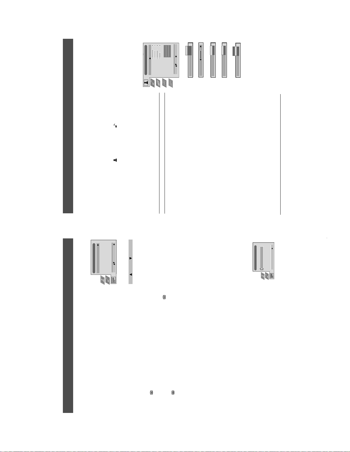
Audio Adjustment
Using the TV menu system:
Sound Control
Item Effect/Operation
Equaliser Mode
Equaliser
Adjustment
Equaliser Mode V Personal
0
Balance
Vocal
Loudness
Space
Jazz
Auto Vol. Control
Stereo
Stereo
Confirm: OK
NICAM
NICAM
Select Mode :
Dual Sound
Volume
Dual Sound
Rock
Pop
v Flat (fixed setting, cannot be adjusted)
cutting and boosting the 5 selected frequency bands.
Equaliser adjustment You can adjust the mode selected in Equaliser mode by
(Personal)
Equaliser Adjustment
0
+
Press b or B to select the frequency band then V or v to
adjust the frequency. Finally, press the OK button to store
the new adjustment.
120 150 1,5K 5 K 10 K
–
If you want to store the new setting, you need to set the Equali ser mode to
Sel: Adjust: Confirm:OK
‘Personal’. Personal mode permanently stores the setting, all other modes (Vocal,
Jazz, Rock, Pop) store only until the next mode change.
0
Balance
Balance b More left
On
Space
Loudness
B More right
v On: For music broadcasts
v On: Special acoustic effect
Loudness V Off: Normal
Space V Off: Normal
On
Auto Vol. Control
broadcast signal.
same independent of the broadcast signal (eg
V On: Volume level of the channels will stay the
Auto Vol. Control v Off: Volume level changes according to the
Mono
Stereo
NICAM
Dual Sound
Volume
in the case of advertisements).
V A for channel 1
v B for channel 2
For a stereo broadcast:
V Mono
v Stereo
When NICAM stereo is being broadcast, the indication NICAM appears br iefly on
Dual Sound For a bilingual broadcast:
Can also adjust the volume level of additional equipment
connected to the RCA sockets on the rear of the TV.
the screen.
Headphones
i Volume Adjusts headphone volume.
A
NICAM
Dual Sound
V A for channel 1
v B for channel 2
i Dual Sound For a bilingual broadcast:
13
12
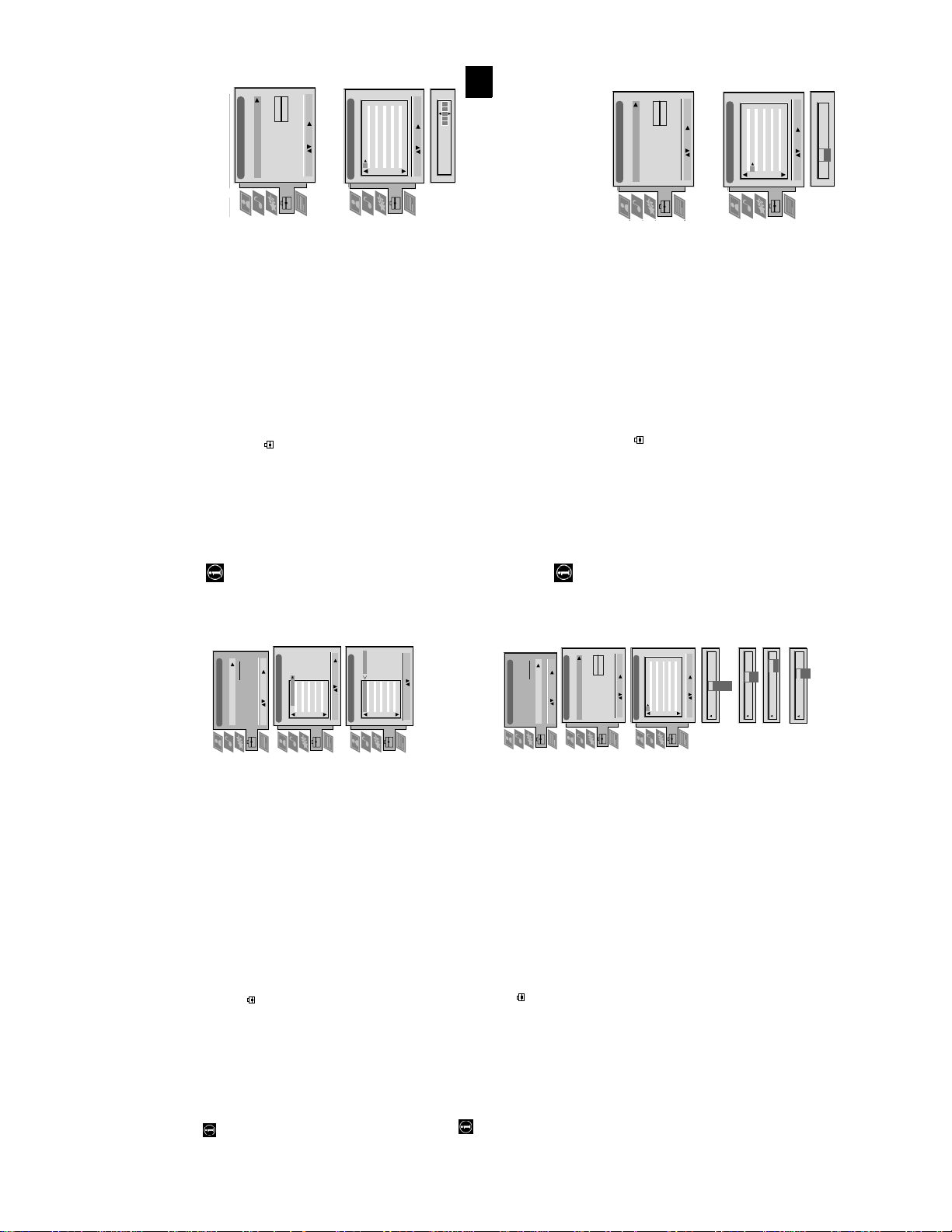
Manual Set Up
Manual Set Up
Language/Country
Language/Country
Manual Programme Preset
Manual Programme Preset
Further Programme Preset
Further Programme Preset
O
O
- - - - - - -
- - - - - - -
RGB Set Up
Picture Rotation
Personal ID
Demo
RGB Set Up
Picture Rotation
Personal ID
Demo
O
Manual Set Up
Language/Country
Manual Set Up
Language/Country
Manual Programme Preset
Manual Programme Preset
Further Programme Preset
Further Programme Preset
O
- - - - - - -
- - - - - - -
RGB Set Up
Picture Rotation
Personal ID
Demo
RGB Set Up
Picture Rotation
Personal ID
Demo
BBC1
BBC
C09
C10
I
I
Off
Off
Off
Off
Off
Off
Off
Off
Select: Enter:
Select: Enter:
5152535455565758596061
Manual Programme Preset
PROG CHSYSSKIP LABEL
F189 - - - Off
Off
Off
On
Off
53 I
Select: Enter:
PROG CHSYSSKIP LABEL
17
ARD
BBC
C09
C10
B/G
B/G
Off
Off
Off
Off
Off
Off
Off
Off
Off
Select: Enter:
Select: Enter:
1 2 3 4 5 6 7 8 91011
Manual Programme Preset
PROG CHSYSSKIP LABEL
C07 TE
Off
Off
Off
SKIP LABEL
6 I
Select: Enter:
PROG CHSYS
Using the TV menu system:
Naming a channel
Names for channels are usually taken automatically from Teletext if available. You can however name a channel or an input
Set Up
video source using up to five characters (letters or numbers).
Auto Tuning
Programme Sorting
1. Press the MENU button on the remote control to display the menu on the TV screen.
- - - - -
Select NexTView
AV Preset
Manual Set Up
Select: Enter :
2. Press the V button to select the symbol on the menu screen then press B to enter the ‘Set
Up’ menu.
PROG CH LABEL
Programme Sorting
menu.
3. Press the V button to select ‘Manual Set Up’ then press B to enter the ‘Manual Set Up’
TV 5
PRO 7
EU-SP
SWF
RTL
SAT
MDR
DDI
C03
C05
C07
C08
C09
C11
C12
C13
1 2 3 4 5 6 7 8 91011
Programme Preset’ menu.
4. Press the V button to select ‘Manual Programme Preset’ then press B to enter the ‘Manual
5. Press the v or V buttons to select the channel you wish to name.
C03 TV 5
DSF
RTL 2
KAB 1
TV 5
PRO 7
EU-SP
SWF
C14
C15
C16
RTL
C03
C05
C07
C08
C09
1 2 3 4 5 6 7 8 91011
PROG CH LABEL
Programme Sorting
Select Prog: Confirm:
confirm. Select the other four characters in the same way.
6. Press the B button repeatedly until the first element of the ‘LABEL’ column is highlighted.
7. Press the v or V buttons to select a letter or number (select ‘-’ for a blank) then press B to
8. After selecting all the characters, press the OK button.
9. Repeat steps 5 to 8 if you wish to label other channels.
10.Press the MENU button to remove the menu from the TV screen.
SAT
MDR
DDI
DSF
RTL 2
KAB 1
C11
C12
C13
C14
C15
C16
Select Position: Move: OK
Set Up
This function enables you to skip unused programme positions when selecting them with the PROGR+/- buttons.
However, by using the number buttons you can still select the skipped programme position.
Skipping programme positions
O
Manual Set Up
Language/Country
Manual Programme Preset
RGB Set Up
Further Programme Preset
- - - - - - -
Picture Rotation
Personal ID
- - - - -
Select: Enter :
AV Preset
Manual Set Up
Select Next View
Auto Tuning
Programme Sorting
‘Set Up’ menu.
menu.
Programme Preset’ menu.
‘SKIP’ column.
1. Press the MENU button on the remote control to display the menu on the TV screen.
2. Press the V button to select the symbol on the menu screen then press B to enter the
3. Press the V button to select ‘Manual Set Up’ then press B to enter the ‘Manual Set Up’
4. Press the V button to select ‘Manual Programme Preset’ then press B to enter the ‘Manual
ARD
BBC
TV 5
PRO 7
EU-SP
SWF
RTL
SAT
MDR
DDI
DSF
C03
C05
C07
C08
C09
C11
C12
C13
C14
C09
C10
B/G
B/G
B/G
B/G
B/G
B/G
B/G
B/G
B/G
Off
Off
Off
Off
Off
Off
Off
Off
Off
1 2 3 4 5 6 7 8 91011
Select: Enter:
Manual Programme Preset
PROG CHSYSSKIP LABEL
Demo
I
L
D/K
B/G
B/G
B/G
Off
Off
EXT
Off
SKIP LABEL
Select: Enter:
1
PROG CHSYS
5. Press the v or V buttons to select the programme position then press B to highlight the
CH
SKIP LABEL
PROG SYS
position) then press the OK button to store.
6. Press the v or V buttons to select ‘Off’ or ‘On’ (if you wish to skip this programme
7. Repeat steps 5 and 6 if you wish to skip or unskip further programme positions.
8. Press the MENU button to remove the menu from the TV screen.
AV1
03
SEARCH
CH
AV1
AV2
F
S
C
Off
1 I
AV3
Off
SKIP LABEL
Off
SKIP LABEL
1 I
0 EXT
PROG SYS
PROG CHSYS
You have already tuned the TV automatically using th e instructions at the start of this manual. You can however carry out
Manually tuning the TV
this operation manually, adding channels to the TV, one at a time.
menu.
Set Up’ menu.
the ‘Manual Programme Preset’ menu.
1. Press the MENU button on the remote control to display the menu on the TV screen.
then press B to highlight the ‘SKIP’ column.
2. Press the V button to select the symbol on the menu screen then press B to enter the ‘Set Up’
3. Press the V button to select ‘Manual Set Up’ on the menu screen then press B to enter the ‘Manual
4. Press the V button to select ‘Manual Programme Preset’ on the menu screen then press B to enter
5. Press the v or V buttons to select a prog ramme numbe r for your channel (eg PROGR 1 for BBC1)
(AV1, AV2, ...) then press B to confirm.
direct frequency inputs then press B to confirm.
number buttons on the remote control or
Press the V button to search for the next available channel.
6. Press v to select ‘OFF’ then press B to highlight the ‘SYS’ column.
buttons to continue searching for the desired channel.
7. Press the v or V buttons to select the TV broadcast system or ‘EXT’ for a video input source
8. Press the v or V buttons to select ‘C’ for terrestrial channels, ‘S’ for cable channels, or ‘F’ for
9. Select the first number digit of ‘CH’ (channel) then the second number digit of ‘CH’ with the
10.If you do not wish to store this channel on the programme number you selected, press the v or V
menu from the TV screen.
11.If this is the channel you wish to store, press the OK button.
16
12.Repeat steps 5-11 if you wish to store more channels then press the MENU button to remove the
After tuning the TV, you can use this feature to change the order of the channels on the TV.
Using the TV menu system:
Re-arranging the TV channels
menu.
1. Press the MENU button on the remote control to display the menu on the TV screen.
2. Press the V button to select the symbol on the menu screen then press B to enter the ‘Set Up’
menu.
3. Press the V button to select ‘Programme Sorting’ then press B to enter the ‘Programme Sorting’
channel then press the OK button to confirm. The selected channel now moves to its new
programme position and the other channels move accordingly.
4. Press the v or V buttons to select the channel you want to move then press B to confirm.
5. Press the v or V buttons to select the new programme position (eg PROG 4) for your selected
6. Repeat steps 4 and 5 if you wish to sort the other channels.
7. Press the MENU button to remove the menu from the TV screen.
13
- - - - -
O
O
O
19
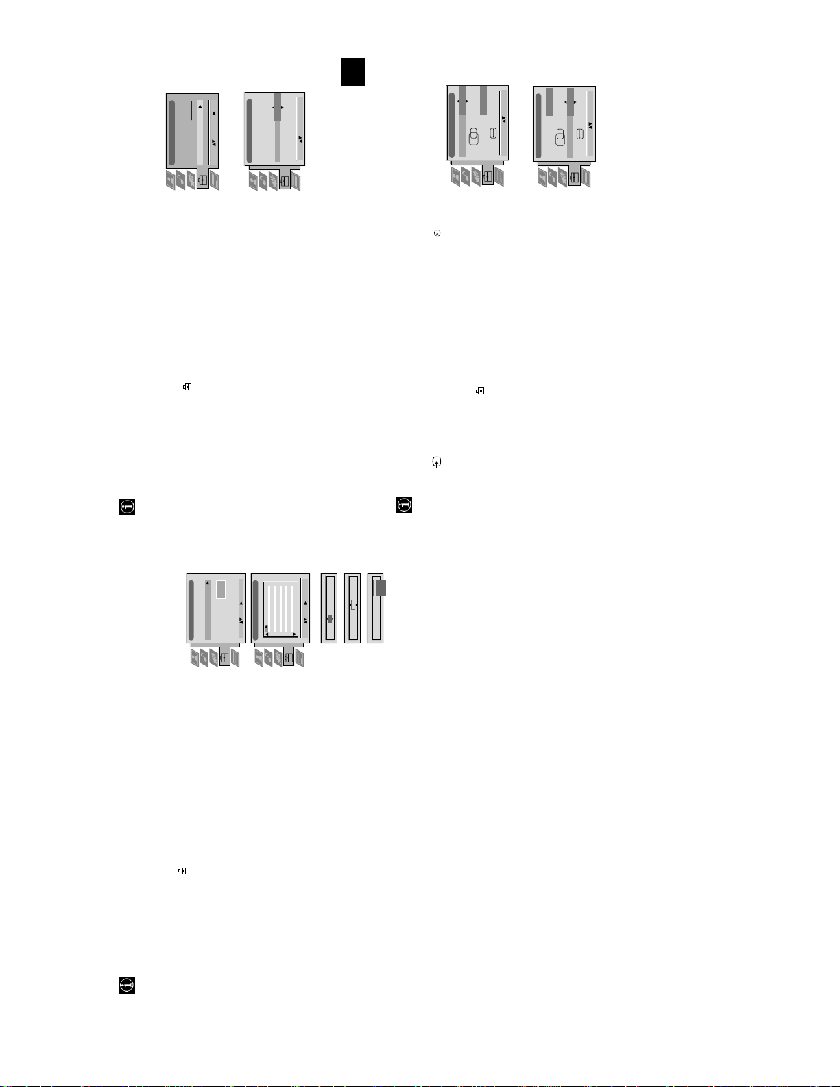
Using the TV menu system:
Because of the earth’s magnetism the picture might slant. In this case you can readjust the picture.
Adjusting the picture rotation
Set Up
RGB Set Up
Manual Programme Preset
RGB Set Up
Further Programme Preset
Picture Rotation
Personal ID
Demo
Rotate: Confirm: OK
Manual Set Up
Select: Enter:
AV Preset
Manual Set Up
Auto Tuning
Programme Sorting
Select Next View
Language/Country
H CentreOH Size
RGB Set Up
Adjust Position: Confirm: OK
H CentreOH Size
Adjust Size: Confirm: OK
1
‘Set Up’ menu
menu.
sub menu.
1. Press the MENU button on the remote control to display the menu on the TV screen.
2. Press the V button to select the symbol on the menu screen then press B to enter the
3. Press the V button to select ‘Manual Set Up’ then press B to enter the ‘Manual Set Up’
button to store.
4. Press the V button to select ‘Picture Rotation’ then press B to enter the ‘Picture Rotation’
5. Press the v or V buttons to rotate the picture over a range of -5 to +5 then press the OK
6. Press the MENU button to remove the menu from the TV screen.
When connecting an RGB source such as a Sony Playstation you may need to readjust the geometry of the picture.
Adjusting the picture geometry for an RGB source
1. Press the button on the remote control to select the connected RGB source .
Up’ menu
‘Manual Set Up’ menu
‘RGB Set Up’ sub menu.
of -10 to +10. Store the new range by pressing the OK button.
2. Press the MENU button to display the menu on the TV screen.
3. Press the V button to select the symbol on the menu screen then press B to enter the ‘Set
4. Press the V button to select ‘Manual Set Up’ on the menu screen then press B to enter the
5. Press the V button to select ‘RGB Set Up’ on the menu screen then press B to enter the
of -10 to +10. Store the new range by pressing the OK button.
6. Press B to select H Centre then press v or V to adjust the centre of the picture over a range
7. Press B to select H Size then press v or V to adjust the horizontal coordinates over a range
8. Press the MENU button to remove the menu from the TV screen.
Using the TV menu system:
With this feature you can a) individually adjust the volume level of each channel, b) manually fine-tune the TV to obtain
Using the Further Programme Preset feature
a better picture reception if the picture is distorted or c) preset the AV output for the programme positions of channels
with scrambled signals (eg from a pay TV decoder). In this way a connected VCR
Manual Set Up
Language/Country
RGB Set Up
Manual Programme Preset
Further Programme Preset
O
- - - - - - -
Picture Rotation
Personal ID
Off
Off
Off
Off
Off
Off
Off
Off
Off
Off
Off
OnOnOnOnOnOnOnOnOnOnOn
00000000000
1 2 3 4 5 6 7 8 91011
Further Programme Preset
PROG AFTVOL DECODER
Select: Enter:
0
1
Select: Enter:
PROG AFTVOL DECODER
PROG AFTVOL DECODER
Off
AV1
AV2
On
1 -5 On
1 -5
PROG AFTVOL DECODER
17
records the unscrambled signal.
Up’ menu
1. Press the MENU button on the remote control to display the menu on the TV screen.
2. Press the V button to select the symbol on the menu screen then press B to enter the ‘Set
Programme Preset’ menu.
3. Press the V button to select ‘Manual Set Up’ then press B to enter the ‘Manual Set Up’ menu.
4. Press the V button to select ‘Further Programme Preset’ then press B to enter the ‘Further
5. Press the v or V buttons to select the relevant programme number then press the B button
pressing the OK button. Repeat steps 5 and 6a if you wish to adjust the volume level of the
repeatedly to select a) VOL b) AFT or c) DECODER. The selected item changes colour.
Press the v or V buttons to adjust the volume level (range -7 to +7) of the channel. Store by
other channels.
b) AFT - Automatic Fine Tuning
Press the v or V buttons to fine tune the channel frequency over a range of -15 to +15. Press
the OK button to confirm. Repeat steps 5 and 6b if you wish to fine tune other channels.
c)DECODER
Press the v or V buttons to select AV1 or AV2 for the programme position then press the OK
5 and 6c to preset the AV output for other programme positions.
button to confirm. You can now attach a decoder to the AV1 or the AV2 socket on the back of
6. a)VOL - Volume Offset
the TV and the picture from that decoder will appear on this programme number. Repeat steps
7. Press the MENU button to remove the menu from the TV screen.
14
Additional Information
Troubleshooting
Here are some simple solutions to problems which may affect the picture and sound.
/
button on the remote control.
• Press the button on the front of the TV.
• If the indicator is on press the button or a numbered
Problem Suggested remedy
No picture (screen is dark), no sound • Plug the TV in.
using the button on the front of the TV.
Adjustment display. Adjust the brightness, picture and colour
balance levels.
to the factory settings.
remote control.
display and adjust the colour setting.
to the factory settings.
• Check the aerial connection.
• Turn the TV off for 3 or 4 seconds and then turn it on again
• Using the MENU system, select the Picture
• From the Picture Adjustme nt display select RESET to return
• Press the button on the remote control.
• If is displayed on the screen, press the button on the
Poor or no picture (screen is dark), but
good sound.
Good picture, no sound
No colour on colour programmes • Using the MENU system, select the Picture Adjustment
the rear of the TV.
• From the Picture Ad justment display select RESET to return
• Turn off any equipment connected to the scart connectors on
Distorted picture when changing
• Contact your nearest Sony service centre.
• Reduce sharpness level.
programmes or selecting Teletext
Remote control does not function • Replace the batteries.
The standby indicator on the TV
flashes
Interference on picture from external
equipment
• If you continue to have these problems, have your TV serviced by qualified personnel.
• NEVER open the casing yourself.
24
Additional Information
Specifications
2x10W (RMS)
Sound output
Left/Right: 2x20W (Music Power)
TV systemIColour system
15W (RMS)
Optional accessory
TV Stand:
KV-28FX65: SU-28FX2
Power consumption
KV-28FX65: 170W
KV-32FX65: 170W
Dimensions (wxhxd)
KV-28FX65: Approx. 796x518x522mm
Weight
KV-28FX65: Approx. 48kg
Sub woofer: 30W (Music Power)
KV-32FX65: Approx. 883x567x562mm
IEC designated size AA batteries (2)
KV-32FX65: Approx. 64kg
Accessories supplied
RM-887 remote control (1)
2000 page TEXT memory, personal ID, sleep timer,
KV-32FX65: SU-32FX2
Other features
Flat display Trinitron tube, noise reduction, graphic equaliser,
without notice.
NexTView.
Design and specifications are subject to change
Receivable Channels Channel Displays
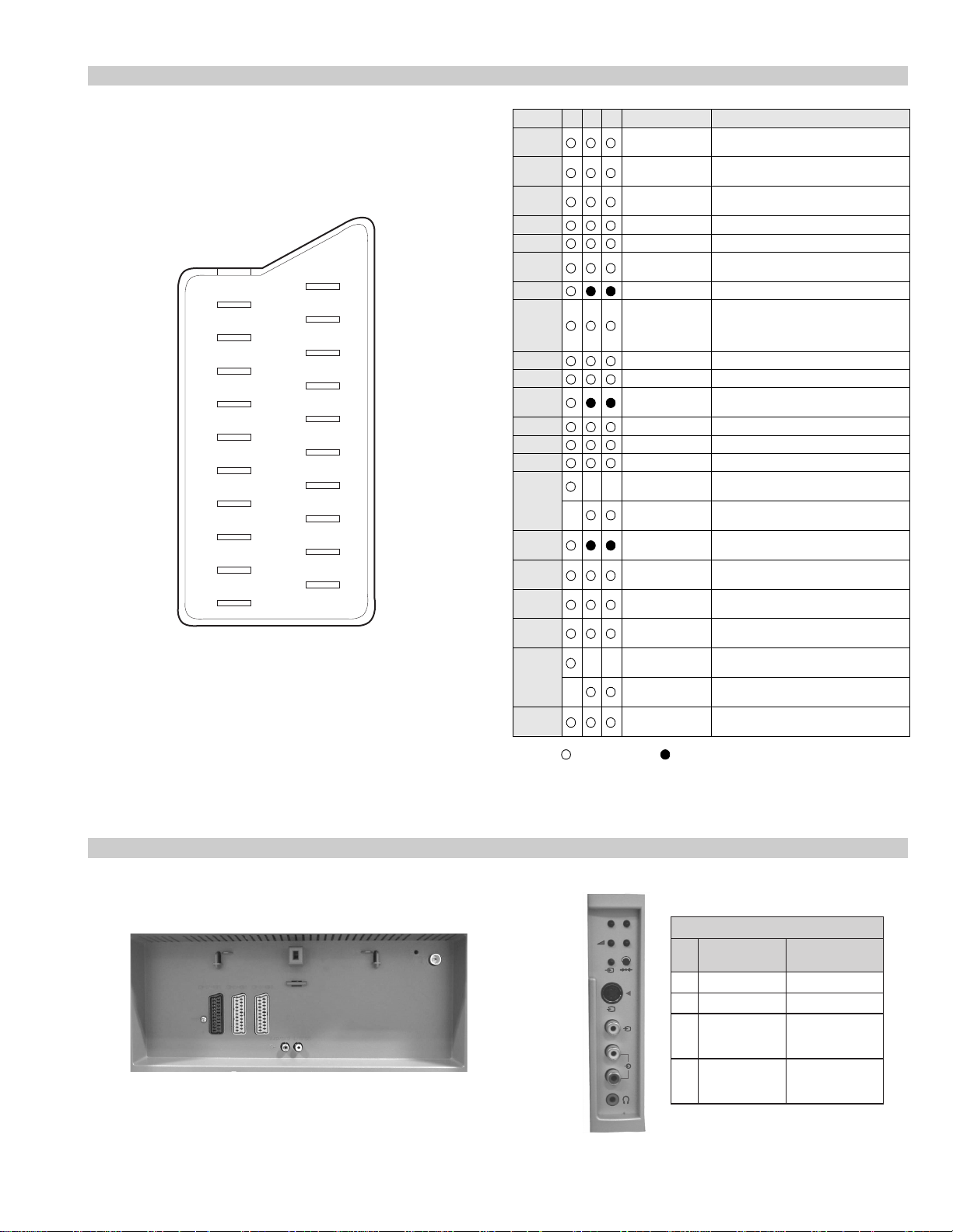
video input, S-video input, Monitor audio/video output.
video input, S-video input, Selectable audio/video output.
video input, RGB input, TV audio/video output.
1
2
3
s
s
/ 21-p in Euro connector (CENELEC standard) including audio/
/ 21-p in Euro connector (CENELEC standard) including audio/
/ 21-pin Euro connector (CENELEC standard) including audio/
2
3
PAL,
SECAM, NTSC 3.58, 4.43 (only Video In)
Channel coverage
See the ‘Channel Display Table’ below.
Picture tube
1
KV-28FX65: FD Trinitron WIDE, Approx. 71cm (28 inches)
KV-32FX65: FD Trinitron WIDE, Approx. 82cm (32 inches)
Rear Terminals
L/G/S/I RCA connectors, variable output for audio signals.
R/D/D/D
RF In
Video input -phono jacks
Audio inputs - phono jacks
S video input - 4 pin DIN
Headphones jack - minijack stereo
4
4
4
s
Front Terminals
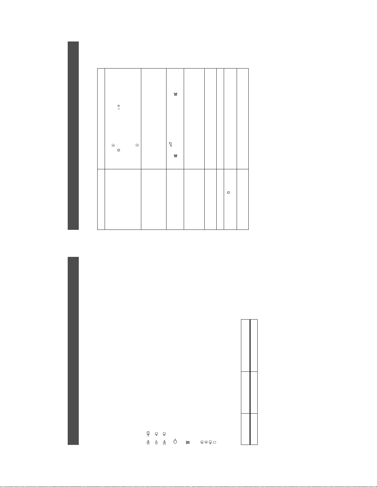
Channel Display Table
I B 21..B69 C21..C69
22
15
SECTION 2 DISASSEMBLY
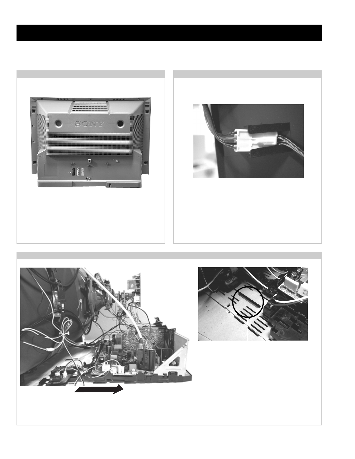
2-1. Rear Cover Removal
<=
<=
=>
=>
=>
=>
Remove the rear cover f ixing screws indicated. T ake care
when removing the rear cover not to damage the speaker
cables [Disconnect the speaker connector] as speakers are
fitted inside the rear cover .
<=
<=
2-2. Speaker Connector Disconnection
<=
<=
<=
Before completely removing the rear cover disconnect the
speaker connector which is located on the inside.
2-3. Chassis Removal and Refitting
T o remove lift the main bracket rear slightly and slide the
chassis away from the beznet. Ensure that the interconnecting
leads are released from their purse locks to prevent damage
being caused.
When refitting the chassis ensure that the main
bracket is located in the beznet guide slots before
sliding the chassis forwards. Refit the
interconnecting leads in their respective purse locks.
16
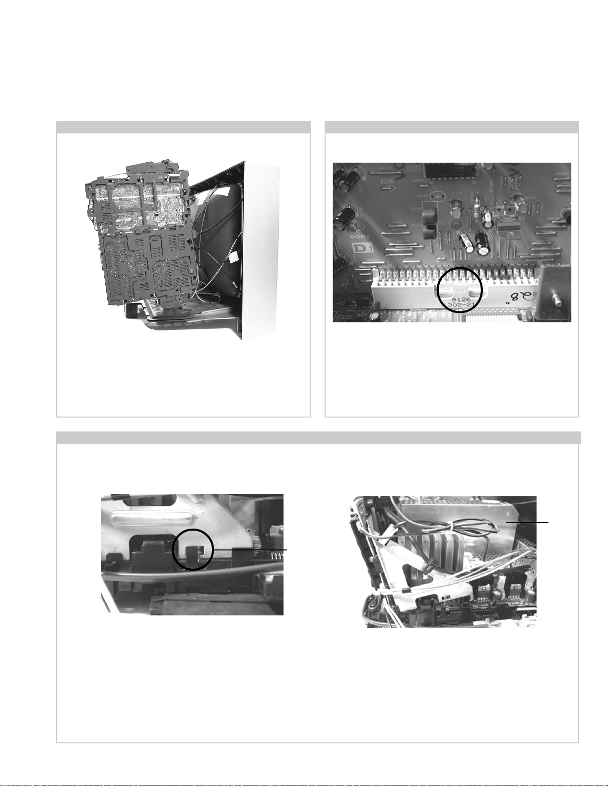
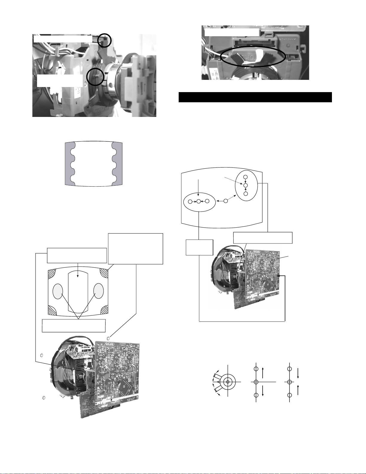
2-4. Service Position 2-5. D1 Board Removal
Position the PWB as indicated to access the solder side.
T o gain access to the D Board follo w the instructions on page
19. [Removal and Replacement of the main bracket bottom
plates ].
2-6. J Board Removal
T o remove the D1 Board release the clip circled and gently
remove the board in a vertical direction.
Shield
case
Clip
Release the two metal bracket support clips located on either side of the chassis. Tilt the bracket very slightly away from the shield
case indicated. Release the J board board socket retaining clip and carefully lift the complete assembly vertically .
17
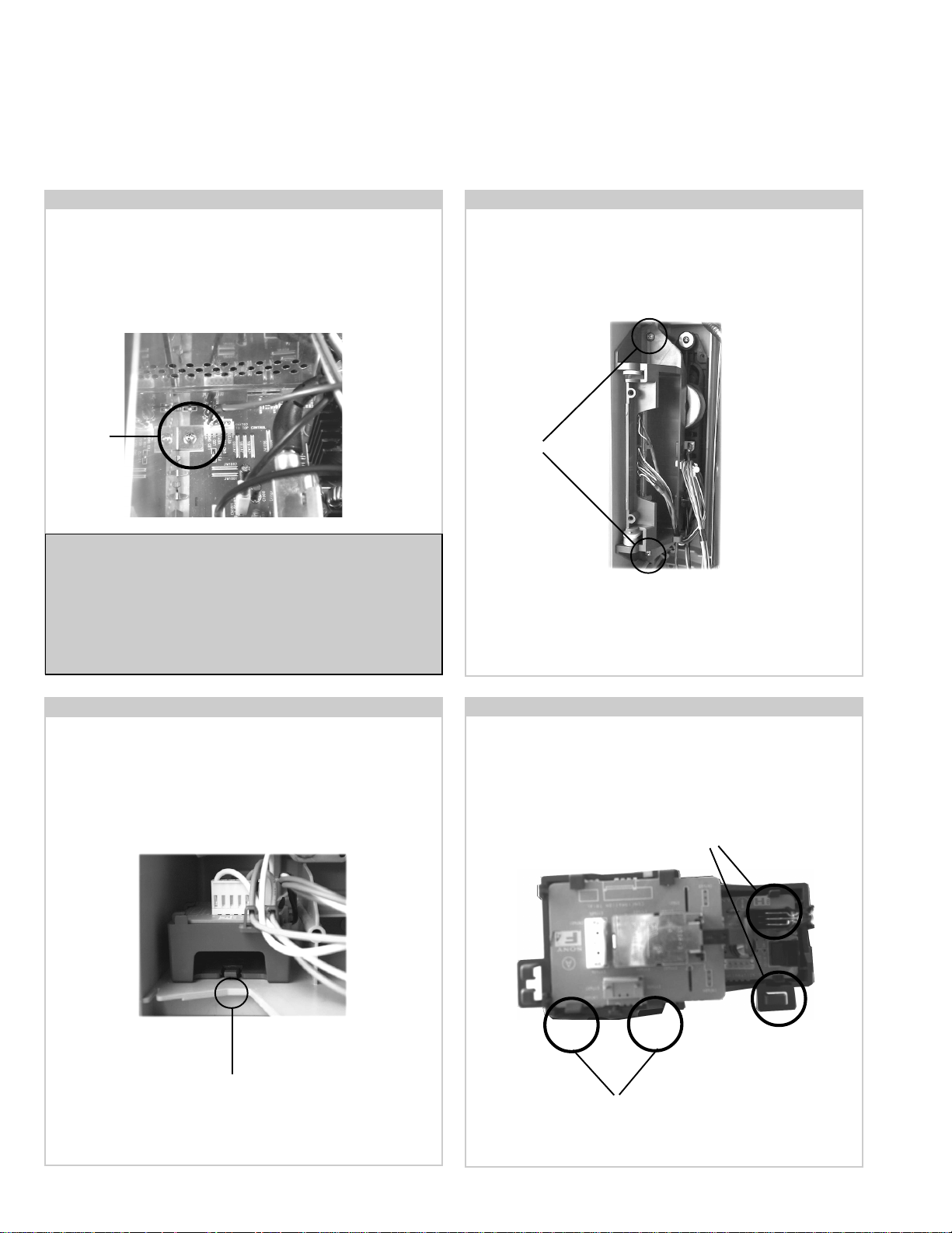
Follow the steps indicated in removal of the J board. With the
assembly removed access to the B1 board shield is possible.
T o remove the shield locate and remov e the two screw s
positioned on either side and at opposite ends of the shield.
Release the B1 board clip and remove in a vertical direction.
Please ensure that the screws are refitted after service.
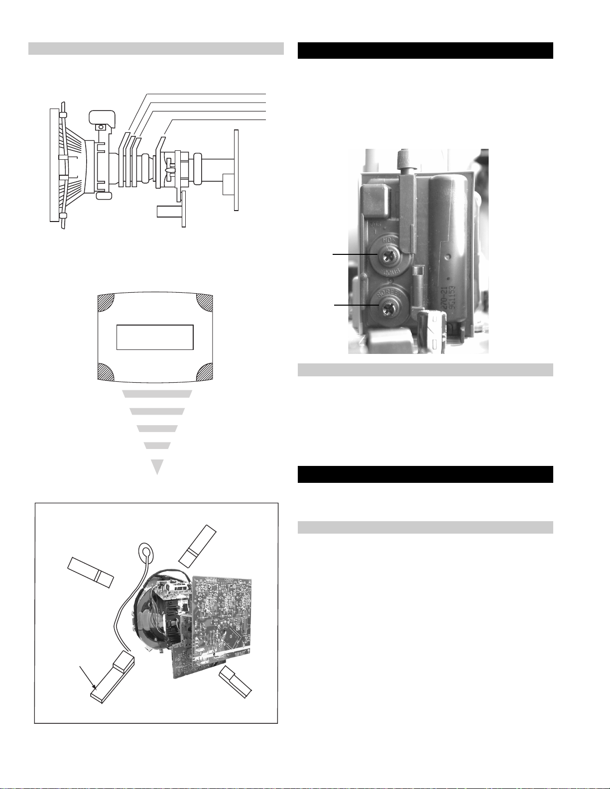
2-8. Side Control Module Removal2-7. B1 Board Removal
Remove the two screws fixing the user control module to the
side of the set. The control module can then be removed by
sliding it towards the rear of the set allowing access to the H7
Board.
Screw
Note :
Removal of the B1, E, and M1 printed circuit boards follows the
same procedure of releasing the securing clips as indicated
in the fig for D1 board removal.
T ake care not to apply to great a pressure to the clips as this may
cause damage.
2-9. F4 Bracket Removal
Release the clip circled and pull the bracket towards the rear of
the set. The bracket can then be removed to allow access to the
boards.
Screws
2-10. F4 and H8 Board Removal
T o remove the F4 and H8 Boards release the clips circled and
ease the boards gently away from the support bracket.
Clips
Clip
Clips
18
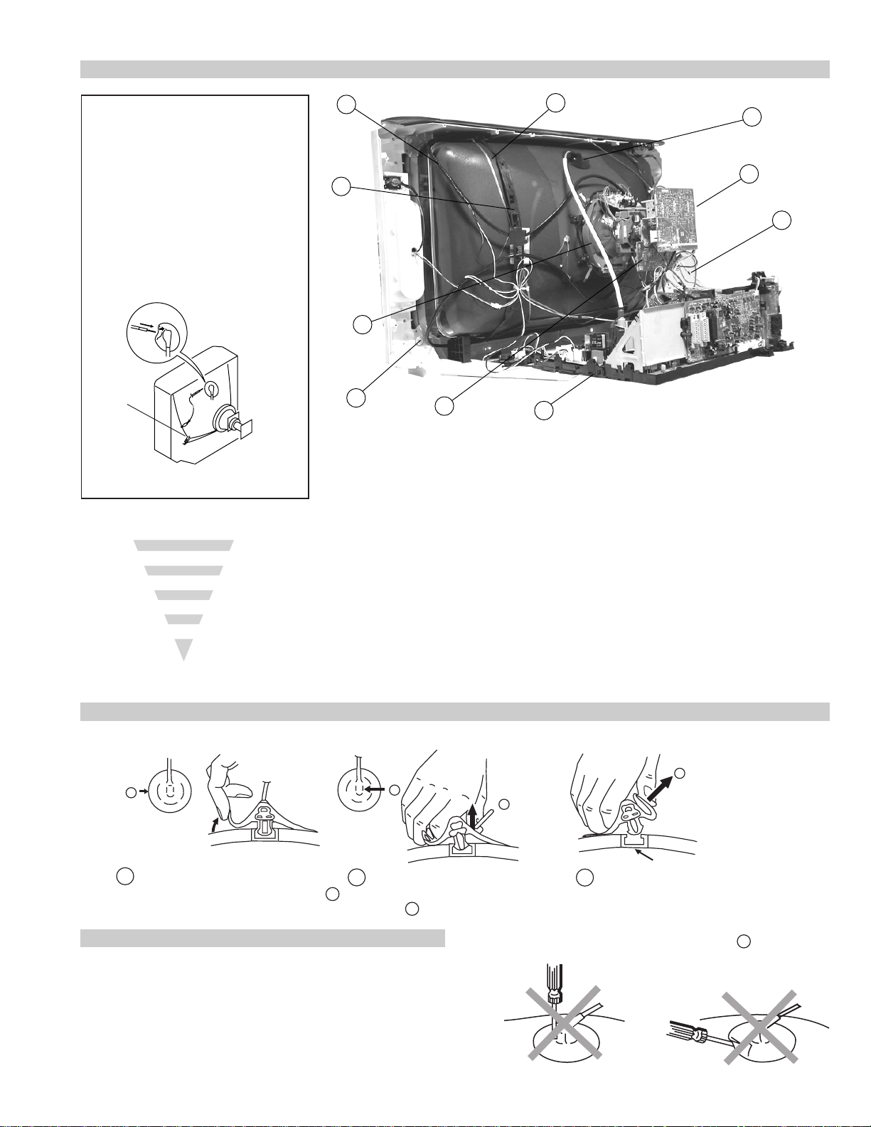
2-11. Picture Tube Removal
WARNING:
BEFORE REMOVING
THE ANODE CAP
High voltage remains in the CRT even
after the power is disconnected. To
avoid electric shock, discharge CRT
before attempting to remove the anode
cap. Short between anode and CRT
coated earth ground strap.
Coated Earth
Ground Strap
8
9
1
3
7
2
6
10
5
4
1. Discharge the anode of the CRT and remo ve the anode cap.
2. Unplug all interconnecting leads from the Deflection yoke, neck
assy, de gaussing coils and CRT grounding strap.
3. Remove the C Board from the CRT .
4. Remove the chassis assembly.
5. Loosen the Neck assembly fixing screw and remove.
6. Loosen the Deflection yoke fixing screw and remove.
7. Place the set with the CRT face down on a cushion and remove
the Degaussing Coil holders.
8. Remove the Degaussing Coils.
9. Remove the CRT grounding strap and spring tentioners.
10. Unscrew the four CRT fixing scre ws [ located on each CR T
corner ] and remove the CR T .
[T ake care not to handle the CR T by the neck.]
Removal of the Anode-Cap
* REMOVING PROCEDURES.
a
1
Turn up one side of the rubber cap in
the direction indicated by the arrow a
b
2 Using a thumb pull up the rubber cap
firmly in the direction indicated by the
arrow b
How to handle the Anode-Cap
1. To prevent damaging the surface of the anode-cap do not use
sharp materials.
2. Do not apply too great a pressure on the rubber, as this may cause
damage to the anode connector.
3. A metal fitting called a shatter hook terminal is fitted inside the
rubber cap.
4. Do not turn the rubber foot over excessively, this may cause damage
if the shatter hook sticks out.
c
b
Anode button
3 When one side of the rubber cap is
separated from the anode button, the
anode-cap can be removed by turning
up the rubber cap and pulling it up in
the direction of the arrow c
19
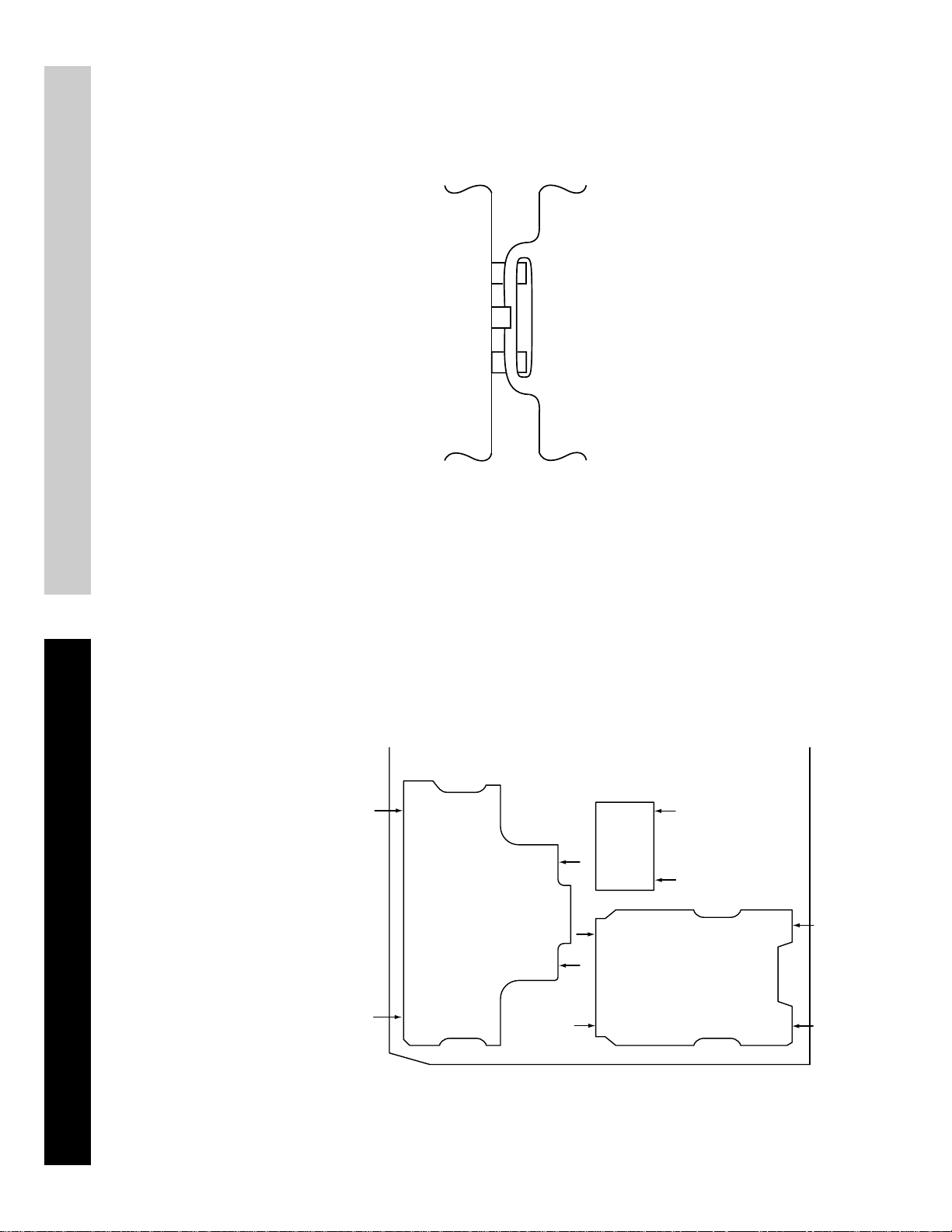
For safety reasons, on no account should the plates be
removed and not refitted after servicing.
£
Because the plates differ in size it is important that the correct plates are refitted in their original
location.
Please note that the plates need to be rotated 180 degrees from their cut position to allow the
(2) REFITTING THE PLATES
tabs to be fitted into their catch positions.
Catch
Tab
REMOV AL AND REPLA CEMENT OF THE MAIN-BRACKET
BOTT OM PLA TES.
Only remove the necessary plate to gain access to the printed wiring board.
In the event of servicing being required to the solder side of the D Board printed wiring board,
the bottom plates fitted to the main chassis bracket require to be removed.
This is performed by cutting the gates with a sharp wire cutter at the locations indicated by the
arrows.
(1) REMOVING THE PLATES
Note : There are 3 plates fitted to the main bracket and secured by3 gates.
20
SECTION 3 SET -UP ADJUSTMENTS
• When complete readjustment is necessary or a new picture tube is
installed, carry out the following adjustments.
• Unless there are specific instructions to the contrary, carry out
these adjustments with the rated power supply .
• Unless there are specific instructions to the contrary, set the
controls and switches to the following settings :
Contrast .................................. normal
Brightness .................................. normal
3-1. Beam Landing
Preparation :
1. In order to reduce the influence of geomagnetism on the set’s
picture tube, face it in an easterly or westerly direction.
2. Switch on the TV set’s power and degauss with a degausser.
(1) Adjustment of Correction Magnet for Y-Splitting Axis.
1. Input a crosshatch signal from the pattern generator.
2. Set the Picture control to minimum and confirm that the
Brightness control is set to normal.
3. Position the neck assembly as indicated in Fig.3-3.
4. Loosen the deflection yoke fixing screw .
5. Move the deflection yoke as far forward as is possible.
6. Adjust the upper and lower pin symmetrically by opening or
closing the Y -splitting axis correction magnets located on the neck
assembly. [See Fig 3-1 and Fig 3-2]
7. Return the deflection yoke to its original position and re-tighten its
fixing screw.
Fig.3-1
Y-splitting axis correction magnet
Carry out the adjustments in the following order :
3-1. Beam Landing.
3-2. Convergence.
3-3. Focus.
3-4. White Balance.
Note : Test equipment required.
1. Color bar/pattern generator.
2. Degausser.
3. Oscilloscope.
4. Digital multimeter.
Caution :
High voltages are present on the Deflection yoke terminals - take care
when handling the Deflection yoke whilst carrying out adjustments.
(2) Landing
Note : Before carrying out the following adjustments adjust the
magnets as indicated below [See Fig.3-4].
1. Input a crosshatch signal from the signal generator.
2. Rough-adjust the focus and horizontal convergence.
3. Switch from the crosshatch pattern to an all-red pattern.
4. Move the deflection yoke backwards and adjust with the purity
magnet so that the red is at the centre and it aligns
symmetrically [See Fig.3-5].
5. Move the deflection yoke forward to the point where the entire
screen just becomes red [Mark its position].
6. Move the deflection yoke further forward until the screen just
changes colour at the edges. [Mark its position]
7. Position the deflection yoke between the two marks indicated
above.
8. Input a crosshatch pattern from the pattern generator and rotate the
deflection yoke so that the horizontal lines are parallel with the top
and bottom of the screen.
9. When the position of the deflection yoke has been determined,
fasten it with its fixing screw.
10. Switch the pattern generator to green then blue and confirm the
purity.
11. If the beam does not land correctly in all the corners of the screen,
use disk magnets to correct it. [Confirm the corner landing for
green and blue]
Fig.3-2
21
Fig.3-3
G1
G2
+
G3
Neck assy
Align the edge
of the neck assy with
the edge of the G2 grid
on the G3 side.
B
G
R
B
G
R
Fig.3-4
Purity magnets
Align pips on
each magnet
GREEN
RED
Align both Purity magnets
to the vertical position
BLUE
Purity control magnets
3-2. Con vergence
(1) Screen centre convergence [Static convergence]
1. Input a dot pattern signal from the pattern generator.
2. Normalize the picture setting.
3. [Moving vertically], adjust the V.STAT magnet so that the
vertical red, green and blue dots coincide at the centre of the
screen.
Center dot
R
G
B
Fig.3-5
Purity control corrects
this area
a
cd
b
Deflection yoke positioning
corrects these areas
Disk magnets or
rotatable disk
magnets correct
these areas (a-d)
R
G
B
H STAT
convergence
control
V.STAT Vertical Static Magnet
C Board
RV5375 (H STAT)
H STAT Convergence
(on mount side)
By opening or closing the V.STAT magnet, the red green and blue
dots move in the direction indicated below .
Disk Magnets
Note: Do not adjust the H.STAT by rotating the V.STAT
magnets as this can affect the focus setting.
22

4. Correction for HMC [Horizontal mis-converg ence] and VMC
+
+
+
YCH VR
Deflection Yoke
+
+
+
TLV VR
Deflection Yoke
HTRAP VR
+
+
+
Deflection Yoke
[V ertical mis-con verg ence] by using the BMC [Hexapole] magnet.
a). HMC correction by BMC [Hexapole] magnet and movement of
the electron beam.
HMC correction(A) HMC correction(B)
A > B
A < B
RG B
RGB
HTIL correction can be performed by adding a THL correction
assembly to the Deflection yoke.
A = B
RG B
A = B
RG B
b). VMC correction by BMC [Hexapole] magnet and movement of
the electron beam.
VMC correction(A) VMC correction(B)
C < D
C
D
C = D C > D C = D
R
G
B
R
C
G
D
B
R
G
B
R
G
B
HAMP Adjustment
YCH Adjustment
TL V Adjustment
Adjust the HAMP using HAMPL and HAMPR registers in the
Dynamic Convergence section of the service menu.
HTIL Adjustment
THL Correction assy
H-TRAP Adjustment
The H-TRAP should not be adjusted unless absolutely necessary as it
affects the TLV settings.
23
Layout of each control
Purity magnet
BMC (Hexaploe) magnet
V STAT convergence magnet
Y-splitting axis correction magnet
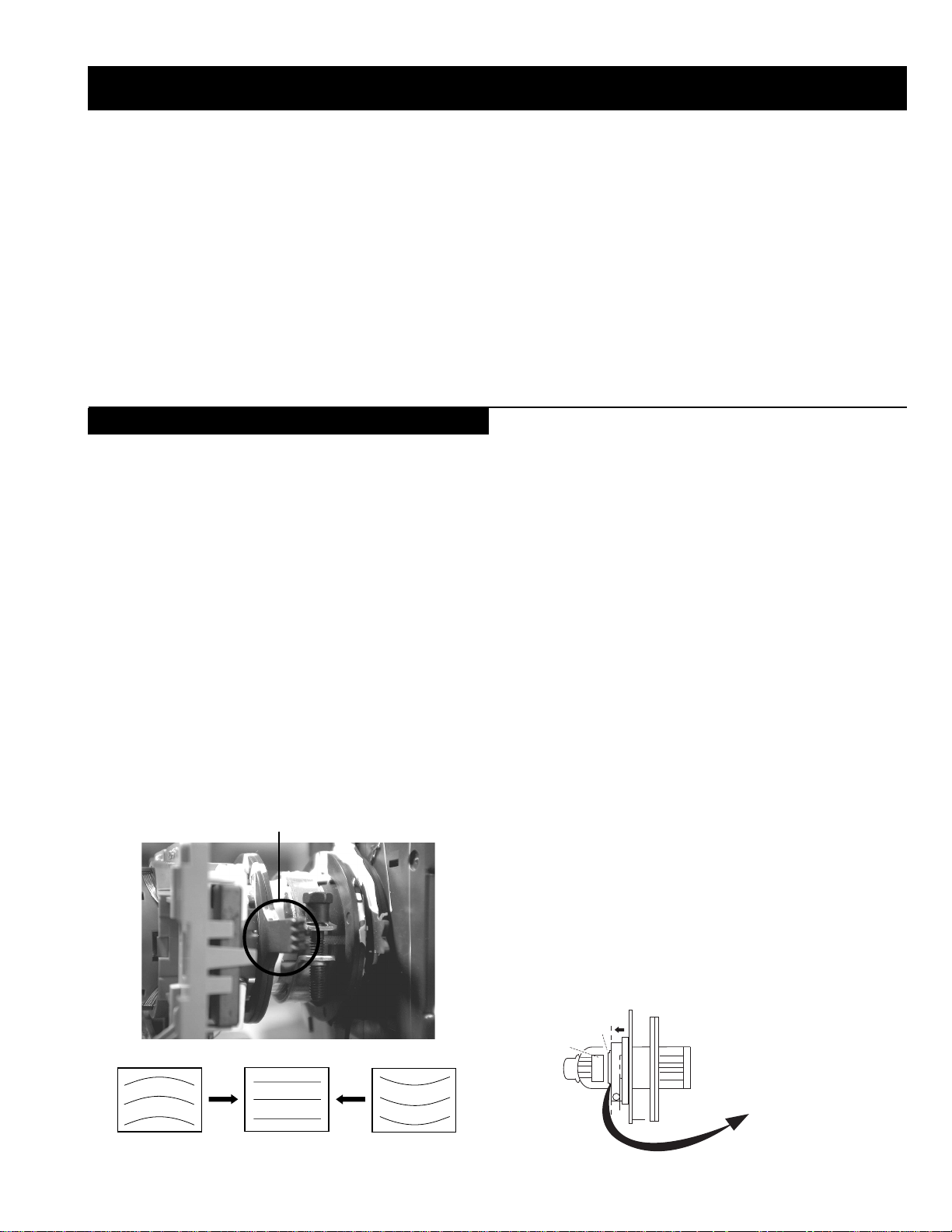
3-3. Focus, Screen (G2) Adjustment
1. Receive a television broadcast signal.
2. Normalize the picture setting.
3. Adjust the focus control located on the flyback transformer to
obtain the best focus at the centre of the screen.
Bring only the centre area of the screen into focus, the magentaring appears on the screen. In this case, adjust the focus to
optimize the screen uniformly.
Note : If you are unable to adjust the corner convergence properly,
this can be corrected with the use of permalloy magnets.
a
a-d: screen-corner
convergence defect
c
Install the permalloy assembly
for the area that needs correcting.
b
d
a
b
Permalloy Assy
X-4387-214-1
c
d
Convergence adjustment with permalloy
Focus
Control
No
Function
G2 adjustment [RV5376]
1. Input a dot signal from the pattern generator.
2. Set the Picture, Brightness and Colour to minimum.
3. Apply 170V DC from an external power supply to the R, G and B
cathodes of the CRT .
4. Whilst watching the picture, adjust the G2 control R V5376
[SCREEN] located on the C Board to the point just before the
flyback return lines disappear.
3-4. White Balance Adjustment
[Adjustment in the service mode using the remote
commander]
White balance adjustment for TV mode
1. Input an all-white signal from the pattern generator .
2. Enter into the ‘Service Mode’ by pressing ‘TEST’, ‘TEST’ and
‘MENU’ ‘MENU’ on the Service Commander .
3. Select ‘Backend’ from the on screen menu display and press
‘OK’.
4. The ‘Backend’ menu will appear on the screen.[See Page 26]
5. Set the ‘Contrast’ to MAX.
6. Set the ‘R-Drive’ to 41.
7. Adjust the ‘G-Drive’ and the ‘B-Drive’ so that the white
balance becomes optimum.
8. Press the ‘OK’ button to write the data for each item.
9. Set the ‘Contrast’ to MIN.
10. Set the ‘R-Cutoff’ to 31.
11. Adjust the ‘G-Cutoff’, and the ‘B-Cutof f’ with the left and
right buttons on the remote commander so that the white balance
becomes optimum.
12. Press the ‘OK’ button to write the data for each item.
24
SECTION 4 CIRCUIT ADJUSTMENTS
4-1. Electrical Adjustments
Service adjustments to this model can be performed using the supplied Remote Commander RM-887.
How to enter into the Service Mode
p
- +
1. Turn on the main power switch of the set while pressing P + (plus) and P - (minus) buttons on the
side pop out control panel.
2. When the picture appears release the P+ and P- buttons.
s
4
4
MONO
L/G/S/I
4
R/D/D/D
3. ‘TT’ will appear in the upper right corner of the screen.
4. Press the ‘MENU’ button twice on the remote commander to obtain the service menu on the
screen.
RESET DEVICES
Backend
Deflection
Ext Deflection
Dynamic Convergence
Colour Decoder 1
Feature Box
Audio/Video Switch
D/A Converter
Sound
SERVICE MENU
Initialising
Reset Devices
Monitoring
Device Register Setting
Special Adjustment
Select :
INITIALISING
Model Setting
Destination Setting
Basic Setting
Feature Setting
Next Menu
MONITORING
Device Status monitor
Error Monitor
Production Monitor
NVM Monitor
Format Monitor
CNI Monitor
4. Push the joystick up or down on the remote commander to select the adjustment item.
5. Push the right button to proceed to the next menu.
6. If the required adjustment item is ‘Deflection’, push the down button to move to ‘Deflection’.
7. Push the joystick to the right to enter into ‘Deflection’.
8. Change the data in order to comply with each standard.
Note :
• Before performing any adjustments ensure that the correct model has been selected in the ‘Model Setting’ menu.
• After carrying out the service adjustments, to prevent the customer accessing the ‘Service Menu’ switch the TV set OFF and then ON.
25

Initialising Menu
Basic Setting
gnisilaitinI
gnitteSledoM
gnitteSnoitanitseD
gnitteScisaB
gnitteSerutaeF
:tceleS:unemtxeN
Model Setting
The menu contains a list with all the available models of this software to
set up the TV set in an easy way . The selection of a model is setting data
for its features and hardware resources which cannot be detected by the
automatic power on H/W detection as well as a special model byte to get
an unique model identification for models which cannot be differed by
features and hardware resources (e.g. KV -28FC60 and
KV-28FC60Z)
Before data is set, the user will be asked if he really wants to set a new
model. If the user agrees, automatically the destination setting menu is
shown.
gnitteSledoM
106CF82-VK
2Z06CF82-VK
306CF92-VK
406CF23-VK
5Z06CF23-VK
606CF43-VK
757QF82-VK
857QF92-VK
957QF23-VK
0157QF43-VK
1107SF82-VK
2107SF23-VK
3107SF63-VK
4156XF82-VK
5156XF92-VK
6156XF23-VK
7156QF92-VK
KCALBytimrofnoCoN=
NEERGledoMelbitapmoC=
DERatadllarofytimrofnoC=
eseR
t
Table.4-1
Indication of Model Compatibility.
Black:
If any data does not match to specific model, the model name is
displayed in black.
Green:
All data which is checked by model setting menu concurs to model
except model byte.
Red:
All data which is checked by model setting menu concurs to model
including model byte.
gnittescisaB
oNrcseDniMxaMataD
1G/B.sySFFONONO
2K/D.sySFFONONO
3L.sySFFONOFFO
4)KU(I.sySFFONOFFO
5)LRI(I.sySFFONONO
6noitpo.taNTXT143
7TRC9:61FFONOFFO
8refoow-buSFFONONO
9yb-dnatsotuAFFONONO
01retlif-bmoCFFONOFFO
11tedCYotuAFFONONO
21tedbmocotuAFFONOFFO
31elbaliavA2VAFFONONO
41elbaliavA3VAFFONONO
51elbaliavA4VAFFONONO
61raer&rF3VAFFONOFFO
71epaTMACESFFONOFFO
81etuMdnuoS1VAFFONOFFO
Table.4-2
Feature Setting
gnitteserutaeF
oNrcseDniMxaMataD
1GPEFFONONO
Table.4-3
Device Register Setting
dnekcaB
noitcelfeD
noitcelfeDtxE
ecnegrevnoCcimanyD
1redoceDruoloC
retrevnoCA/D
dnEhgiHerutaeF
hctiwSoediV/oiduA
dnuoS
Table.4-4
Note:
After selecting a model, it may be necessary to reset some devices to get
the correct data. (Treble/Bass Offset of Sound, deflection adjustments,
...)
26

1redoceDruoloC
oNrcseDfeDniMxaMataD
1tniT1303613
2wGN/PFFOFFONOFFO
3DIN/PFFOFFONOFFO
4ruoloCbuS70517
5rtnoCbuS80518
6OFprahS1031
7QEprahS2032
8niaGprahS80518
9veLtuO-Y5303653
01tnioPSB0030
11veLtuO-C5403654
21tseRCD0030
31OFFPB2032
41QFPB1031
51wSretliFFFOFFONOFFO
hctiwSoediV/oiduA
dnekcaB
oNrcseDfeDniMxaMataD
1no-RNOFFONONO
2no-GNOFFONONO
3no-BNOFFONONO
4loc-DFFOFFONOFFO
5sixa-roloC2032
6tsartnoC0403604
7vuL-timiL3033
8euH2303623
9ruoloC1303613
01leveL-ITC2032
11ssenthgirB1303613
21ammaG3033
31ssenprahS0303603
41evirD-R1403614
51evirD-G1403603
61evirD-B1403632
71edoM-LBA0030
81thgirBbuS1303622
91leveL-MV2031
02ffotuC-R1303613
12revoerP2032
22ffotuC-G1303632
32leveL-CIPD1031
42ffotuC-B1303692
52narT-CD0030
62tnoC-buS70519
72lvL-2BGRL80510
82lbA-P5105151
92oF.prahSNOFFONONO
03W-gnigAFFOFFONOFFO
13B-gnigAFFOFFONOFFO
231tesffo-BC110 5111
331tesffo-RC110 5111
432tesffo-BC70517
532tesffo-RC70517
63roloCbuS08-82-
oNrcseDfeDniMxaMataD
11TUOVC0070
22TUOVC2072
3WS1DGFFOFFONOFFO
4WS2DGFFOFFONOFFO
51TUOCY0070
62TUOCY1071
7LRTC0OLFFOFFONOFFO
8LRTC1OLFFOFFONOFFO
91TUOA3073
012TUOA3073
11ETUM3TUOAFFOFFONOFFO
21WSDCZNOFFONONO
313TUOA3073
41LEDPUORG5101351
51R/L3TUOA0030
61FLOV3TUOA0070
71CLOV3TUOA3073
Table.4-5
tnemtsujdAlaicepS
oNrcseDniMxaMataD
1levelBGR070
2niaGBGR0138
3leveLtaPBGR070
4niagtaPBGR01351
5wFartxE0552552
6kcehCskhCGPEFFONONO
7hgiHrecilSFFONONO
8ediWWCFFFONONO
9RNgepMFFONOFFO
01retliFhctoNFFONOFFO
11petSDLN7-00
21petSDKP51-00
31petSDRC0517
41petSPHS01-0351petSLOC01-0161petSniagPHS5-00
71petSlevelMV3-00
812VACYotuACSTNFFONOFFO
913VACYotuACSTNFFONOFFO
02elbasiDBGRFFONOFFO
12DGnretnIFFONONO
22tuOxiMCY2VAFFONONO
Table.4-6
Table.4-7
Table.4-8
27

)tnoc(1redoceDruoloC
dnuoS
oNrcseDfeDniMxaMataD
61wSparT-C0010
71parTD-SNOFFONONO
81FPLNOFFONONO
91LD-Y80018
02bmoC-NNOFFONONO
12leSoediV00510
22leSBGR0030
32enotflaHFFOFFONOFFO
421.FFOrC70517
521.FFObC70517
622.FFOrC70517
722.FFObC70517
82qerFDCV3073
92edoMDCV0031
03SNESCFA1031
13MVMFFOFFONOFFO
23jdAY-R-S60516
33jdAY-B-S40514
43FPH/LLEB2032
53OFLLEBFFOFFONOFFO
63PG-S0030
73DISFFOFFONOFFO
83BNE1BGRFFOFFONOFFO
93HP-SH1010
04OITARN/S3033
Table.4-9
ecnegrevnoCcimanyD
oNrcseDfeDniMxaMataD
1egnaR3603636
2tatSV6303671
3tatSH3303613
4LpmaH7303633
5RpmaH6303633
6YpU1303613
7YwoL3303613
8LpuY0303654
9RpuY0303613
01LwolY1303613
11RwolY0303654
21LpUwobM1303613
31RpUwobM2303613
41LwoLwobM2303613
51RwoLwobM2303613
61lrtCProCTFFOFFONOFFO
71niProCpoT1303613
81lrtCProCBFFOFFONOFFO
91niProCtoB3403613
Table.4-10
oNrcseDfeDniMxaMataD
1leveL.feR0400204
2niag-otuANOFFONONO
3ni-anA0010
4etum-rraCNOFFONONO
5tuokcolCNOFFONONO
6niag-MANOFFONONO
7edompilC 0020
8loV1TRACS970 72197
9loV2TRACS970 72197
01rPTRACS720 72172
11rp-1S2I610 72161
21rp-2S2I610 72161
31rpMF720 72172
41rp-ciNGB350 72135
51rp-ciNL950 72195
61rp-ciNKD350 72135
71rp-ciNI790 72179
81rp-ciNlrI790 72179
91yaceD-CVA2082
02lov-WbuS0721-00
12qerf-WbuS0250402
22ssaPH-WbuSFFOFFONOFFO
32erts-tapS721+01-721
42ffeoC-tapS0080
52sffossaB03-3+0
62sffoelberT03-3+0
72sffonduoL0090
82sffoloV-pH2-5-5+292timiLS-M03+821-721+03
03timiLB-M03-821-721+0313timiLM-S21+821-721+21
23timiLB-S02-821-721+0233timiLM-B21-821-721+2143timiLS-B02+821-721+02
53xaM.rrE040 55204
63niM.rrE810 55281
73sffO.loV06-04-
Table.4-11
noitcelfeD.txE
oNrcseDfeDniMxaMataD
1ytiraeniL7210552721
2ertneCH1303613
3parTH1303613
4noitatoR005520
5esahPsucoF7210552721
Table.4-12
28
 Loading...