

Sony KV-28FS20U Service manual
SERVICE MANUAL
BE-3E
CHASSIS
MODEL
KV-28FS20U
COMMANDER DEST CHASSIS NO.
RM-887 UK SCC-Q25G-A
MODEL
COMMANDER DEST CHASSIS NO.
1

TABLE OF CONTENTS
Section Title Page Section Title Page
Specifications .................... 3
Connectors .................... 4
Self Diagnostic Software .................... 5
1. GENERAL
Overview of the Remote Control................... 9
AutomaticallyTuning the TV .................... 9
Rearranging the TV Channels .................... 10
Adjusting the Picture .................... 10
Adjusting the Sound .................... 11
Setting up Dolby Pro Logic .................... 11
Changing the Screen Mode .................... 12
Choosing a Language .................... 12
ManuallyTuning the TV .................... 13
T eletext .................... 13
Specifications .................... 14
Troubleshooting .................... 14
2. DISASSEMBLY
2-1. Rear Cover Removal .................... 15
2-2. Chassis Assy Removal .................... 15
2-3.1 Service Position (1) .................... 15
2-3.2 Service Position (2) .................... 15
2-4. Wire Dressing .................... 16
2-5. A Board Removal .................... 16
2-6. A Extension Board .................... 16
2-7. Picture Tube Removal .................... 17
Bottom Plates .................... 18
3. SET-UP ADJUSTMENTS
3-1. Beam Landing .................... 19
3-2. Convergence .................... 20
3-3. Screen (G2), White Balance ................... 22
3-4. Focus Adjustment .................... 22
3-5. White Balance .................... 23
.
CAUTION
SHORT CIRCUIT THE ANODE OF THE PICTURE TUBE AND THE
ANODE CAP TO THE METAL CHASSIS, CRT SHIELD, OR THE
CARBON PAINTED ON THE CRT, AFTER REMOVAL OF THE
ANODE CAP.
4. CIRCUIT ADJUSTMENTS
4-1. Electrical Adjustments .................... 24
4-2. TT T est Mode .................... 27
4-3. T T est Mode .................... 28
5. DIAGRAMS
5-1. Block Diagram (1) .................... 29
Block Diagram (2) .................... 31
Block Diagram (3) .................... 33
Block Diagram (4) .................... 35
5-2. Circuit Board Location .................... 36
5-3. Schematic Diagrams and
Printed Wiring Boards .................... 37
* C Board .................... 37
* D Board .................... 39
* A1 Board .................... 44
* J1 Board .................... 45
* VM Board .................... 47
* J2 Board .................... 49
* D2 Board .................... 50
* D1 Board .................... 51
* A Board .................... 54
* H Board .................... 63
5-4. Semiconductors .................... 67
5-5. IC Blocks .................... 69
6. EXPLODED VIEWS
6-1. Chassis .................... 71
6-2. Picture Tube .................... 72
7. ELECTRICAL P ARTS LIST .................... 73
ATTENTION
APRES AVOIR DECONNECTE LE CAP DE’LANODE,
COURT-CIRCUITER L’ANODE DU TUBE CATHODIQUE ET CELUI
DE L’ANODE DU CAP AU CHASSIS METALLIQUE DE L’APPAREIL,
OU AU COUCHE DE CARBONE PEINTE SUR LE TUBE
CATHODIQUE OU AU BLINDAGE DU TUBE CATHODIQUE.
ATTENTION !!
WARNING !!
AN ISOLATION TRANSFORMER SHOULD BE USED DURING ANY
SERVICE WORK TO AVOID POSSIBLE SHOCK HAZARD DUE TO
LIVE CHASSIS, THE CHASSIS OF THIS RECEIVER IS DIRECTLY
CONNECTED TO THE POWER LINE.
SAFETY-RELATED COMPONENT WARNING !!
COMPONENTS IDENTIFIED BY SHADING AND MARKED
THE SCHEMATIC DIAGRAMS, EXPLODED VIEWS AND IN THE
PARTS LIST ARE CRITICAL FOR SAFE OPERATION. REPLACE
THESE COMPONENTS WITH SONY PARTS WHOSE PART
NUMBERS APPEAR AS SHOWN IN THIS MANUAL OR IN
SUPPLEMENTS PUBLISHED BY SONY.
£
ON
AFIN D’EVITER TOUT RISQUE D’ELECTROCUTION PROVENANT
D’UN CHÁSSIS SOUS TENTION, UN TRANSFORMATEUR
D’ISOLEMENT DOIT ETRE UTILISÈ LORS DE TOUT DÈPANNAGE
LE CHÁSSIS DE CE RÈCEPTEUR EST DIRECTMENT RACCORDÈ
Á L’ALIMENTATION SECTEUR.
ATTENTION AUX COMPOSANTS RELATIFS Á
LES COMPOSANTS IDENTIFIÈS PAR UNE TRAME ET PAR UNE
MARQUE
EXPLOSÈES ET LES LISTES DE PIECES SONT D’UNE IMPOR-
TANCE CRITIQUE POUR LA SÈCURITÈ DU FONCTIONNEMENT,
NE LES REMPLACER QUE PAR DES COMPSANTS SONY DONT LE
NUMÈRO DE PIÈCE EST INDIQUÈ DANS LE PRÈSENT MANUEL
OU DANS DES SUPPLÈMENTS PUBLIÈS PAR SONY.
£
SUR LES SCHÈMAS DE PRINCIPE, LES VUES
LA SECURITÈ!!
2
LEDOMMETI metsySnoisiveleT metsySoeretS egarevoClennahC metsySroloC
KUIoeretSMACIN96B-12B:FHU
ledoM U02SF82
noitpmusnoCrewoPW321
,34.4CSTN,LAP
)NIOEDIV(85.3CSTN
ediWnortinirTDF
)sehcni82(mc17xorppA
ebuTerutciP
)yllanogaid
0
201
noitcelfed
derusaemerutcipmc66xorppA(
]RAER[slanimreTtuptuO/tupnI
tuptuodnuoS
rekaepstfeLdnathgiR
refooWbuS
rekaepsertneC
dnuorruS
stnemeriuqeRrewoPV042-022
.slangisoediVdnaoiduArofstupnI
rotcennocoruEnip-12:1
)dradnatsCELENEC(
.BGRrofstupnI
oiduAdnaoediVVTfostuptuO
snoisnemiDmm525x694x167xorppA
.slangis
.slangisoediVdnaoiduArofstupnI
rotcennocoruEnip-12:2
)dradnatsCELENEC(
.oediVSrofstupnI
oiduAdnaoediVrotinoMfostuptuO
thgieWgk44xorppA
)elbatceles(.slangis
skcaJonohP
slangiSoiduArofsrotcennoCtuptuO
seirosseccAdeilppuS
slanimretrekaepslanretxE)5(NIDnip2 serutaeFrehtOkniltramS,dnuorruSybloD,txeteleT
]TNORF[slanimreTtuptuO/tupnI 788-MR
kcajenohpdaeHkcajinimoerets metsyslortnocetomeRlortnocderarfnI
stupnioiduAskcajonohp stnemeriuqerrewoP
tuptuooediVkcajonohp snoisnemiD)d/h/w(mm32x44x902xorppA
tupnioediVSNIDnip4 thgieW)yrettabgnidulcniton(g98xorppA
)rewoPcisuM(W02x2
)rewoPcisuM(W02
)rewoPcisuM(W01x1
)rewoPcisuM(W5x2
)1(rednammoCetomeR788-MR
)2(yrettab6RdetangisedCEI
)1(rekaepSertneC
)2(srekaepSdnuorruS
cdV3
noitangisedCEIseirettab2
)AAezis(6R
.ecitontuohtiwegnahcottcejbuserasnoitacificepsdnangiseD
WARNING (UK Models only)
The flexible mains lead is supplied connected to a B.S. 1363 fused plug
having a fuse of 13 AMP rating. Should the fuse need to be replaced,
use a 13 AMP FUSE approved by ASTA to BS 1362, ie one that
carries the
IF THE PLUG SUPPLIED WITH THIS APPLIANCE IS NOT SUITABLE
FOR THE OUTLET SOCKETS IN YOUR HOME, IT SHOULD BE CUT
OFF AND AN APPROPRIATE PLUG FITTED. THE PLUG SEVERED
FROM THE MAINS LEAD MUST BE DESTROYED AS A PLUG WITH
BARED WIRES IS DANGEROUS IF ENGAGED IN A LIVE SOCKET.
When an alternative type of plug is used, it should be fitted with a
13 AMP FUSE, otherwise the circuit should be protected by a 13 AMP
FUSE at the distribution board.
ASA
T
mark.
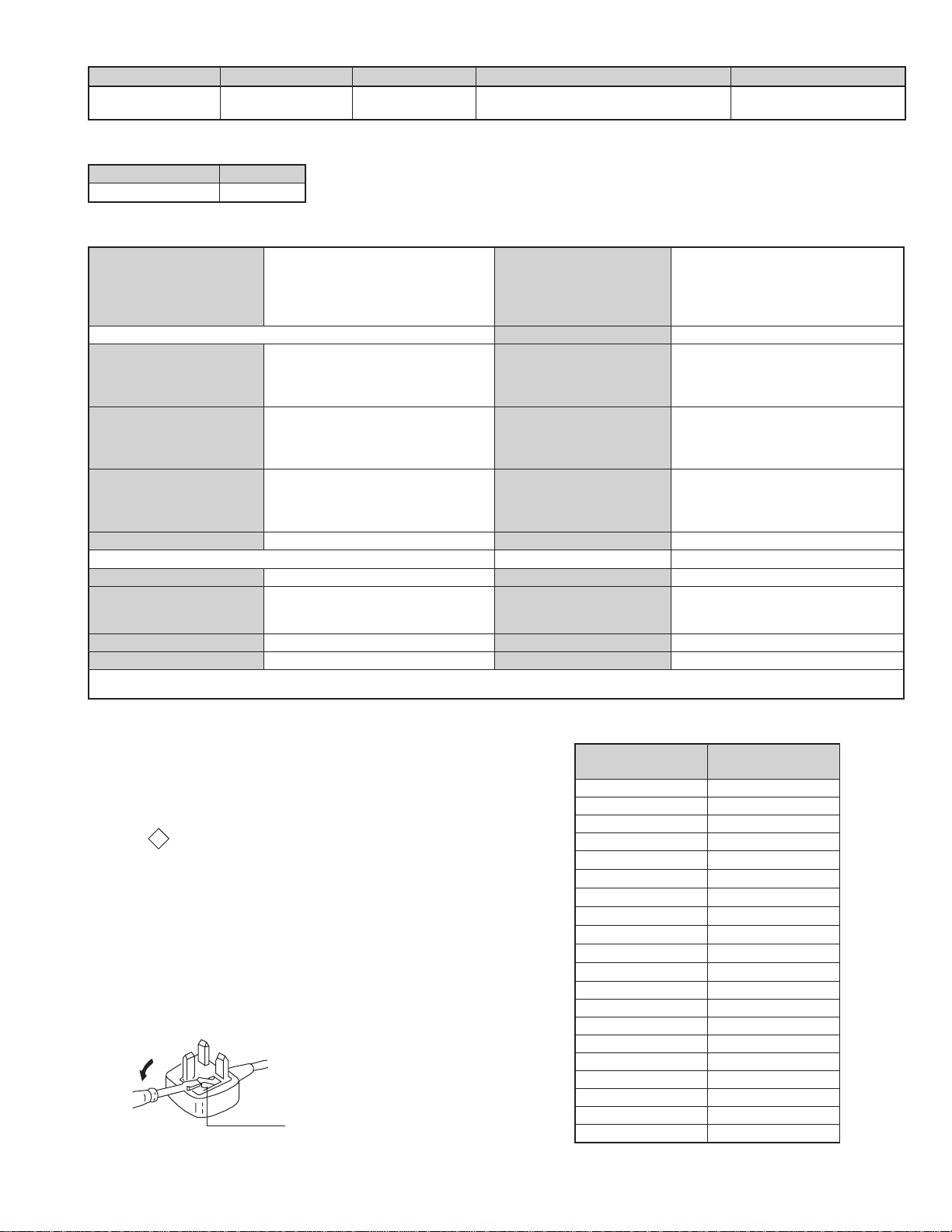
How to replace the fuse.
Open the fuse compartment with
a screwdriver blade and replace
the fuse.
FUSE
metI
emaNledoM
bmoClaPFFO
PIPFFO
ytiroirPBGRFFO
xoBrefooWNO
1tracSNO
2tracSNO
)3(nitnorFNO
4tracSFFO
rotcejorPFFO
edom9:61niBKANO
G/BmroNFFO
ImroNNO
K/DmroNFFO
SUAmroNFFO
LmroNFFO
TASmroNFFO
MmroNFFO
txeteleTNO
oeretSmaciNNO
teserPegaugnaLhsilgnE
U02SF82-VK
3
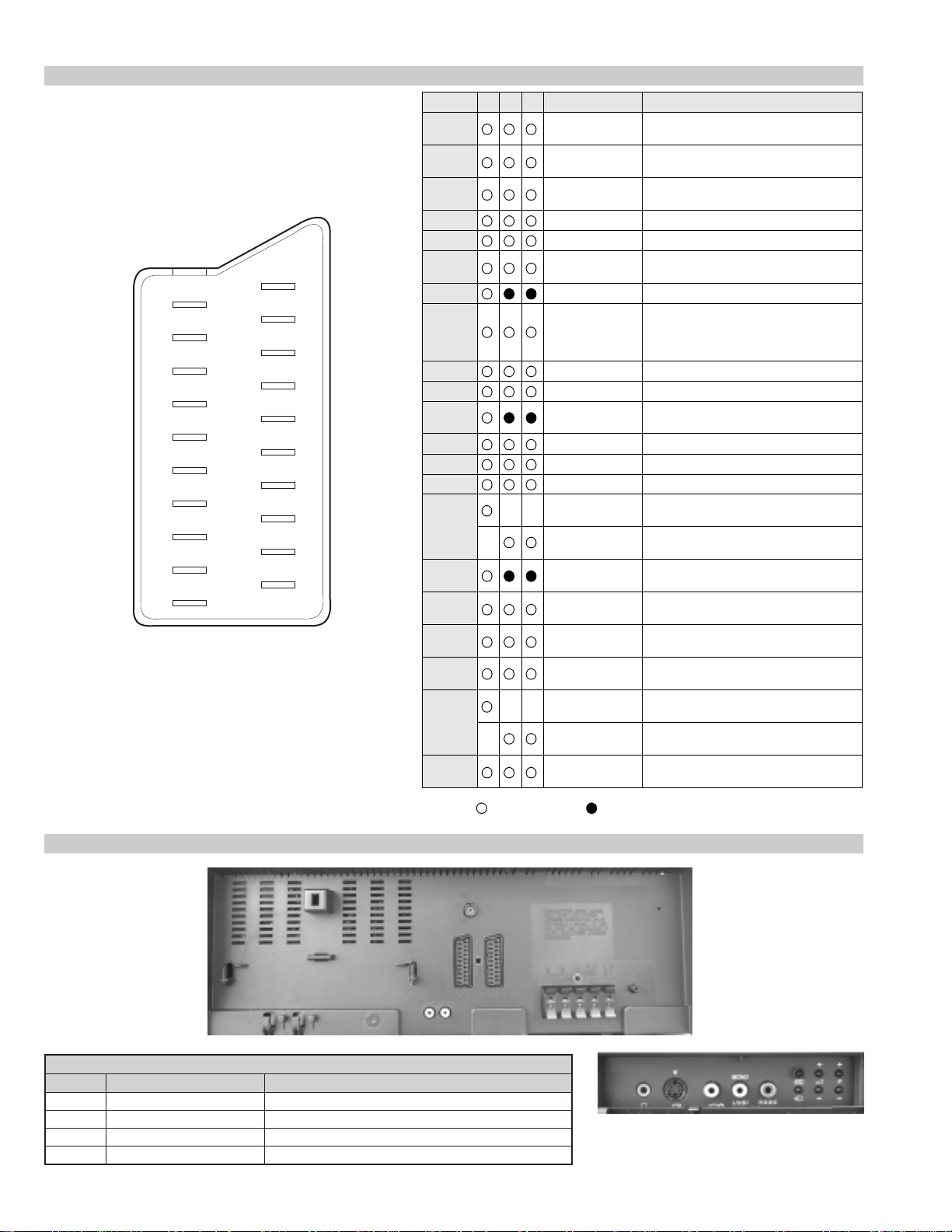
21 pin connector
21
19
17
15
13
11
9
7
5
3
1
20
18
16
14
12
10
8
6
4
2
Pin No 1 2 4 Signal Signal level
1 Audio output B
2
3
4 Ground (audio)
5 Ground (blue)
6 Audio input A
7 Blue input 0.7 +/- 3dB, 75 ohms positive
8 Function select
9 Ground (green)
10 Open
11 Green Green signal : 0.7 +/- 3dB, 75 ohms,
12 Open
13 Ground (red)
14 Ground (blanking)
15
_ (S signal Chroma
16 Blanking input
17 Ground (video
18 Ground (video
19 Video output 1V +/- 3dB, 75ohms, positive sync 0.3V
20
_ Video input
21 Common ground
(right)
Audio output B
(right)
Audio output A
(left)
(left)
(AV control)
_ _ Red input 0.7 +/- 3dB, 75 ohms, positive
input)
(Ys signal)
output)
input)
_ _ Video input 1V +/- 3dB, 75ohms, positive sync 0.3V
Y (S signal)
(plug, shield)
Standard level : 0.5V rms
Output impedence : Less than 1kohm*
Standard level : 0.5V rms
Output impedence : More than 10kohm*
Standard level : 0.5V rms
Output impedence : Less than 1kohm*
Standard level : 0.5V rms
Output impedence : More than 10kohm*
High state (9.5-12V) : Part mode
Low state (0-2V) : TV mode
Input impedence : More than 10K ohms
Input capacitance : Less than 2nF
positive
0.3 +/- 3dB, 75 ohms, positive
High state (1-3V) Low state (0-0.4V)
Input impedence : 75 ohms
(-3+10dB)
(-3+10dB)
1V +/- 3dB, 75ohms, positive sync 0.3V
(-3+10dB)
Connected Not Connected (open) * at 20Hz - 20kHz
Rear Connection Panel
noitarugifnocniptekcosoediVS
oNniP langiS leveLlangiS
1dnuorG2dnuorG3tupni)langisS(Y Bd01+3-V3.0.cnySevitisop,mho57Bd3-/+V1
4tupni)langisS(C.cnySevitisop,mho57Bd3-/+V3.0
S-Video
socket
4
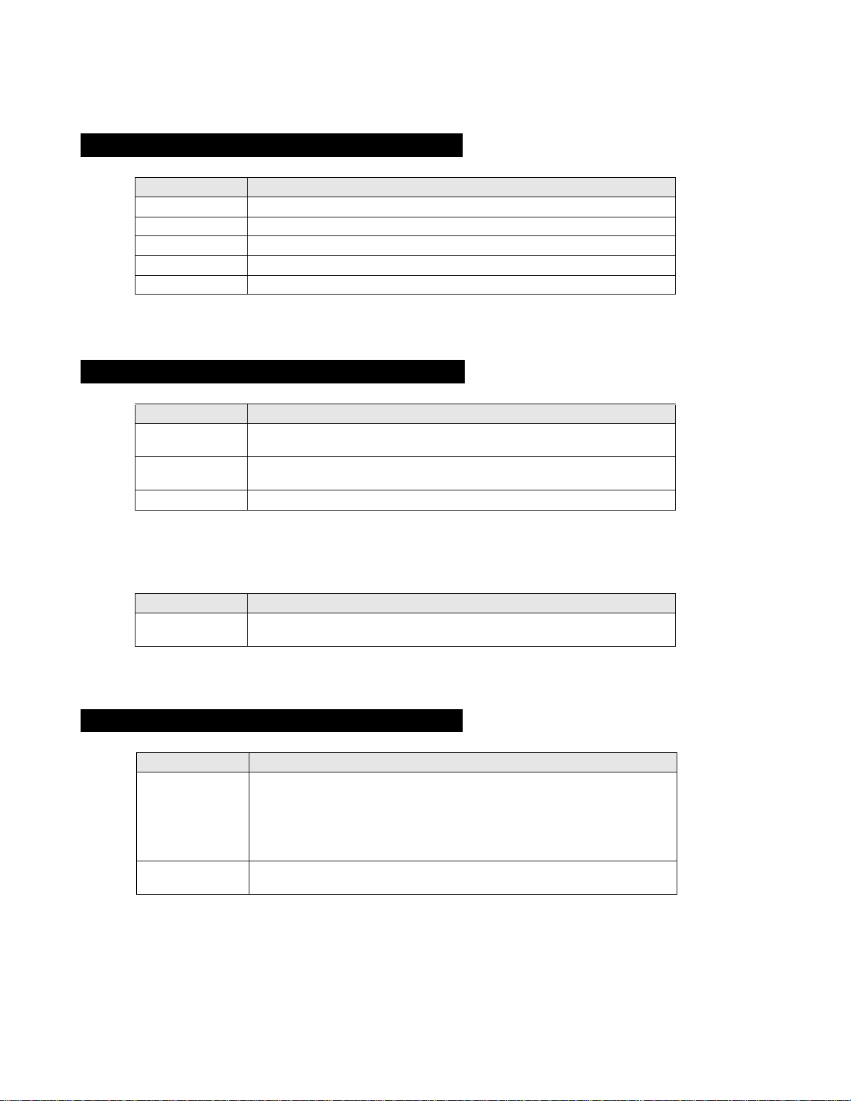
BE-3E SELF DIAGNOSTIC SOFTWARE
The errors indicated below can be read using an Error Reader Display (Part Number S-188-90 0-10) connected to the service conn ector. Once an
error has been detected it will then be displayed on the two digit error reader. During the power up procedure and during normal run time, the
micro’s self diagnostic procedures monitor for various errors. Errors displayed refer to the table indicated below.
Error Number Error Description
00 No error (TV Error Reader shows 00 in normal condition)
01 Not allowed (may be confused with Sircs response flash on LED)
02 Protection circuit trip (OCP, OVP & No V-Sync)
03 Reserved for OVP (Included in error 2 for BE-3E)
04 Reserved for No V-Sync (Included in error 2 for BE-3E)
05 AKB
06 IIC Scl Low <Power Up only>
07 IIC Sda Low <Power Up only>
08 IIC Sda & Scl Low <Power Up only>
09 Jungle controller no acknowledge <Power Up only>
10 Video Switch (CXA2040) no acknowledge <Power Up only>
11 Tuner no acknowledge
12 MSP no acknowledge
13 NVM no acknowledge
14 AV switch (CXA2089) no acknowledge (DS20 & DX20)
15 Not used
16 Port Expander (CXA1875) no acknowledge (DS20 & DX20)
17 Not used
18 Dynamic Convergence (CXA8070) no acknowledge
19 Cannot Initialise jungle (after initial power on check OK) - <Chassis Initialisation>
20 Jungle controller response failure after power up check (+9V test)
21 Video Switch (CXA2040) cannot power on reset - <Chassis Initialisation>
22 Video Switch (CXA2040) response failiure after power up check (+9V test)
23 NVM acknowledge fail after initialisation (STBY +5V - same as micro!)
24 MSP run-time failure <May Not Be Fatal - Display On Error Reader>
25 DSP run-time failure <May Not Be Fatal - Display On Error Reader>
26 M3L bus Clock low time out after data send <Run-Time Failure>
27 M3L bus Clock low time out after data send <At Power Up Check>
28 M3L bus Clock low time out after data send <At Initialisation>
29 M3L Txd Low <Power Up Only>
30 M3L Rxd Low <Power Up Only>
31 M3L Enable Low <Power Up Only>
32 Compact Text test fail <Power Up Only>
33 Compact Text does not respond (+5V test)
34 Compact text run-time failure <May Not Be Fatal - Display On Error Reader>
5
Protection Error (Error 2):
Once every main loop (approximately 200ms OSD mode, 50ms text or menu mode), the micro checks the protection pin (pin 66). If the protection
pin is high 6 successive times, a protection error is diagno s ed . T he protection pin is not checked during the first 3 - 4 seconds after AC on.
If this error is diagnosed, the respective NVM register will be updated and the set goes straight into diagnostic standby with 2 flashes - no reset is
attempted.
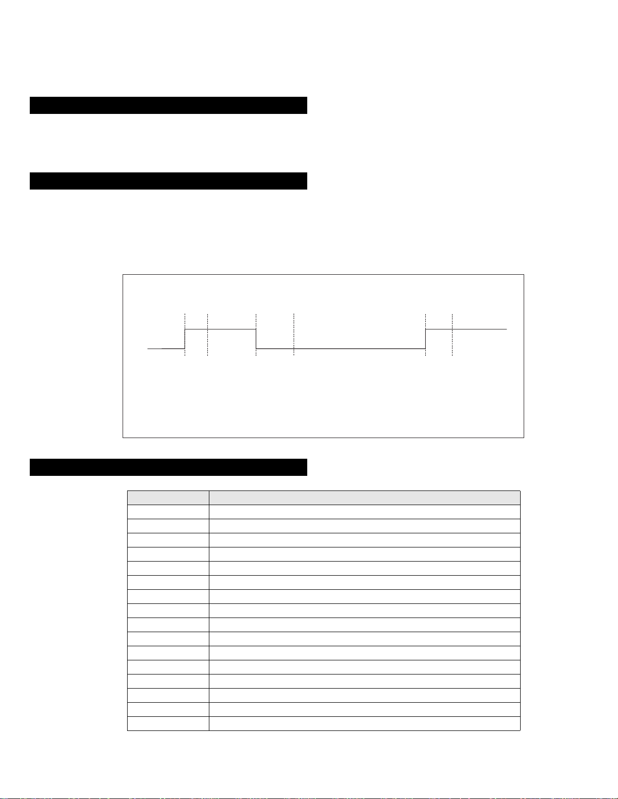
AKB Error (Error 5):
Once every main loop the micro checks the AKB stability by reading the IKR return from the Jungle IC. IKR=1 means that the AKB is stable,
IKR=0 means that the AKB is unstable. If the AKB status is unstable for 10 seconds, an AKB error is diagnosed. AKB stability is not checked
during the first 20 seconds after AC switch on.
If this error is diagnosed, the respective NVM register will be updated and the response LED will flash 5 times continually, but the set will not go
into standby mode. If the AKB status becomes stable, and remains stable for 10 seconds, the LED will stop flashing.
Time / seconds
10090807050 60403020100
IKR
Return
BCD EF
A
A. IKR Return first goes high after 12 seconds.
B. Micro begins checking IKR Return status 20 seconds after power on.
C. Micro detects IKR return = 0.
D. Micro detects that IKR has been 0 for 10 seconds; NVM counter is incremented and the LED
starts flashing (flashes 5 times, off for 2 seconds, flashes 5 times, etc.
E. Micro detects that IKR=1; LED continues to flash.
F. Micro detects that IKR has been high for 10 seconds; LED stops flashing.
Startup Diagnostic Errors (Errors 6-18, 27, 29-32):
NVM Error Description
6 SCL pin low
7 SDA pin low
8 Both SCL and the SDA pins are low
9 No acknowledge from the jungle (CXA2076)
10 No acknowledge from the video switch (CXA2040)
11 No acknowledge from the tuner
12 No acknowledge from the MSP
13 No acknowledge from the NVM
14 No acknowledge from the CXA2089 video switch (DS20 & DX20)
16 No acknowledge from the CXA1875 video Port Expander (DS20 & DX20)
18 No acknowledge from the Dynamic Convergence (CXA8070)
27 M3L_TXD pin low after Compact Text RAM test.
29 M3L_TXD pin low
30 M3L_RXD pin low
31 M3LEN pin low
32 Compact Text RAM test fail
If any of these errors are detected, the re spective NVM register will be incremented. The software will then carry on with the power up sequence.
6
General IIC Device Run-time Errors (Error s 19-23):
NVM Error Description
19 No acknowledge from Jungle when attempting to initialise.
20 No acknowledge from Jungle when attempting to read registers.
21 AV Switch cannot complete reset during initialisation.
22 No acknowledge from AV Switch when attempting to read registers.
23 No acknowledge from NVM when attempting to read or write.
If any of these errors are detected, the respective NVM register will be incremented and the software will carry on.
Compact Text Run-time Errors (Errors 26, 28, 33 & 34):
NVM Error Description
26 M3L_TXD pin low when checking register 81 (implies that no communication was
28 M3L_TXD pin low when attempting to initialise (implies that no communication was
33 Compact Text RAM test failed during initialisation of devices.
In the case of these errors, the ‘device reset’ pin will be held low for 60ms, causing a hardware reset of Compact Text. Following this reset, a
longer timeout will be all owed fo r the M3L b us to recover . If the err o r still e xists, th e NVM register will be incremented and the software will carry
on.
possible).
possible).
NVM Error Description
34 Register 81 check fai l, b ut M3L_TXD pin high (impl ies that Compact Text has either
reset or become corrupted).
In the case, the ‘device r eset’ pin will b e held low for 60ms, causing a har dwar e re set of Compact Text. Compact T e xt will then be r e-ini tialised and
the NVM counter up dated. This is the same as for errors 26, 28 and 33 except that the M3L bus timeo ut is not changed.
MSP and DSP Run-time Errors (Errors 24 & 25):
NVM Error Description
24 Error 24 can be caused by any of the following :
- After MSP initialisation, Scart Prescale Register check fail (implies that the MSP
has either reset or become corrupted).
- MSP fails to acknowledge reset instruction.
- Scart Prescale Register check fail (implies that the MSP has either reset or
become corrupted).
25 - DSP test byte corrupted (implies that the MSP has either reset or become
For both these errors, the software will refresh the MSP and DSP registers. If the errors still exist, the NVM counter will be incremented, and the
software will carry on.
corrupted).
7

Error Display Mode
Error Display Mode is entered by the following sequence of commands :
Standby -> Informati on -> Digit 5 -> Volume Down -> TV
This mode will display a special menu, which will list all possible errors and the number of occurrances of each error (0 - 255, as stored in the
NVM). There will also be a display of the current error (00 if no error). This display mode will appear as follows :
ERROR DISPLAY MODE
Current Error Code = 00
Error Code Occurrences Error Code Occurrences
2 2 19 0
3 -- 20 0
4 -- 21 89
5 0 22 0
6 0 23 0
7 0 24 0
8 0 25 4
9 0 26 5
10 0 27 0
11 0 28 3
12 0 29 0
13 0 30 0
14 3 31 0
15 0 32 0
16 0 33 3
17 0 34 38
18 6
Whilst in this mod e, the number of occurences of each error can be reset to 0 by following sequence of Sircs commands: Digit 8 -> Digit 0.
‘TT08’ will also reset this NVM data.
This mode can only be exited by switching off the TV.
The Current Error Code can also be read by using a TV Error Reader (IIC slave address 42H). This device simply receives 1 data byte, which is the
error number in binary coded decimal form.
8
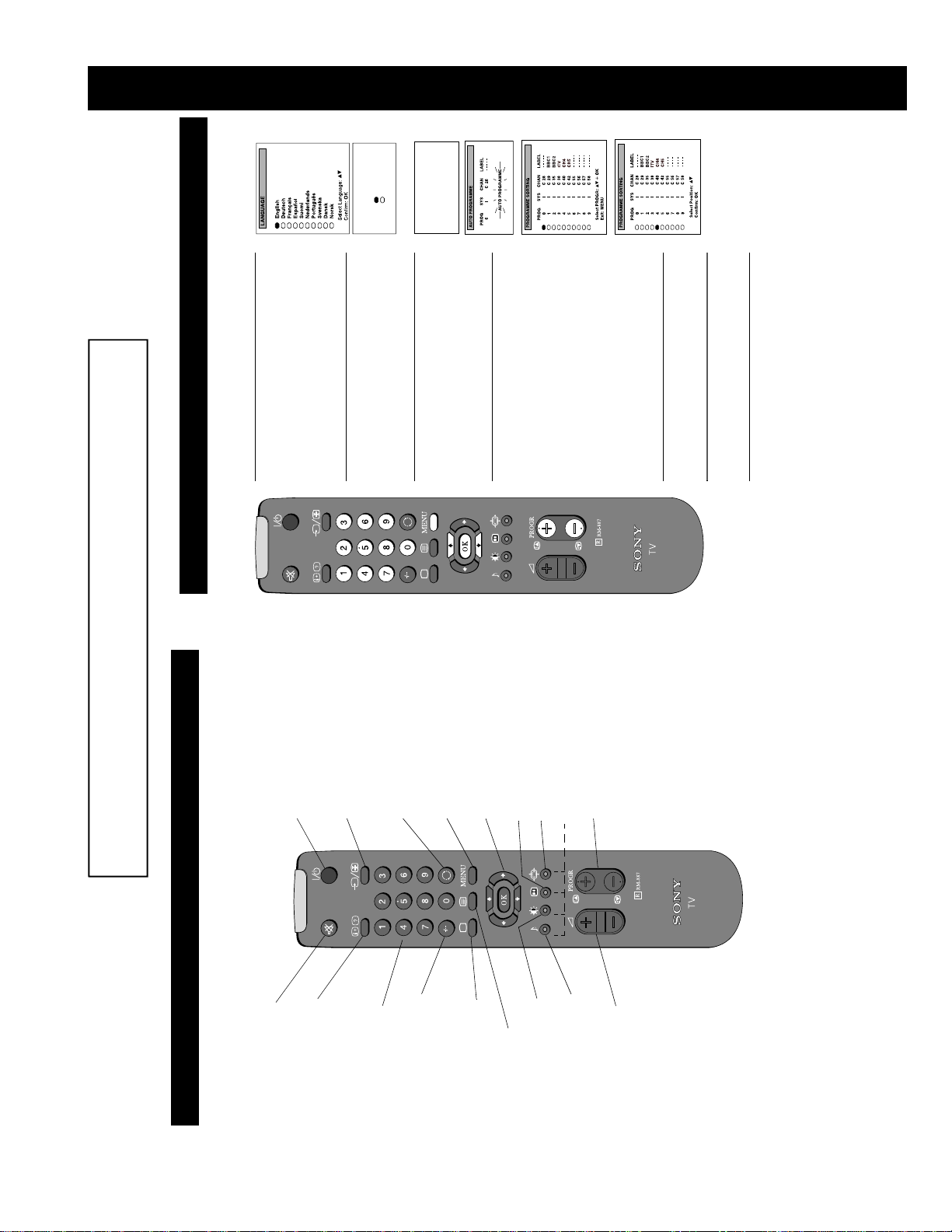
SECTION 1 GENERAL
Yes
No
Confirm: OK
Do you want to start
automatic tuning?
buttons on
v
or
V
‘LANGUAGE’ menu appears automatically on the TV
screen enabling you to select in which language you wish
to read the TV menu screens. Press the
the remote control to select your chosen language then
1. When switching on the TV for the first time, the
buttons to select
v
or
V
your selected language. Press the
press the OK button to confirm your selection.
‘YES’ then press the OK button to confirm.
2. The ‘automatic tuning’ menu appears on the TV screen in
Confirm: OK
Please confirm that
antenna is connected
the OK button to confirm. The TV starts to automatically
search and store all available channels for you. Please be
3. Ensure the antenna is connected as instructed, then press
v
v
or
or
V
V
patient and do not press any buttons.
channels, the ‘PROGRAMME SORTING’ menu appears
on the TV screen enabling you to change the order of the
channels on your TV.
If you do not wish to use this option, proceed to step 5.
If you wish to change the channel order, pr ess the
buttons to select the new programme number position for
your selected channel then press the OK button to
confirm. The selected channel now moves to its new
want to move, then press the OK button. Press the
programme position. Repeat this procedure if you wish to
buttons on your remote control to select the channel you
4. When the TV has finished tuning in all available
screen.
sort the order of other channels on your TV.
5. Press the MENU button to remove the menu from the TV
remote control to view the TV channels.
6. Press the PROGR+/- or the numbered buttons on the
6. Automatically tuning the TV
Quick Start Guide
The operating instructions mentioned here are partial abstracts from the ‘Operating
Instruction Manual’. The page numbers of the ‘Operating Instruction Manual’ remain
as in the manual.
When you first switch on the TV, the following sequence of menu screens appear on the TV enabling you to 1) choose a language
for the TV menu screens, 2) tune channels to the TV, 3) arrange the channels.
To temporarily switch off TV
Press to temporarily switch off TV. Press again to
switch on from standby mode. To save energ y, w e
recommend switching off completely when TV is not
in use.
NOTE: After 15-30 minutes without a TV signal and
without any button being pressed, the TV switches
automatically into standby mode.
To select input signal or freeze teletext
Press to select inputs from the TV sockets (see Using
Optional Equipment section). In teletext mode, press
to freeze the displayed page. Press again to cancel.
To return to previous channel
Press to return to the previous channel you were
watching. Note: This can be done only if you watched
the previous channel for at least 5 second s.
To display the menu
Press if you wish to use the TV menu system. Press
again to remove the menu from the TV screen.
To select menu items
Use these buttons and the OK button to select the
options available in the menu system of this TV.
This button has no function
To change screen format
Press to change the size of the screen.
See Teletext section of manual for details.
To select channels
Press to select channels.
6
Overview
Overview of the remote control buttons
To mute sound
Press to mute TV sound. Press again to
restore the sound.
To reveal on screen information
Press to reveal all on-screen indications.
Press again to cancel. In teletext mode,
press to reveal concealed information (eg
answers to a quiz) then press again to
cancel.
To select channels
Press the numbered buttons to select
channels.
For double digit programme numbers,
e.g.23, press -/-- first, then the buttons 2 and
3. If you enter an incorrect first digit, select
-/-- button again to enter the programme
number of your choice.
To return to TV mode
Press to return to normal operatio n from
teletext mode or standby mode.
To select Teletext
Press to switch on Teletext.
To display picture menu
Press to change the picture settings. Press
the OK button to remove the displa y.
To display sound menu
Press to change the sound settings . Press the
OK button to remove the display.
To adjust TV volume
Press to adjust the volume of the TV.
8
9
Personal
Movie
Live
b button to
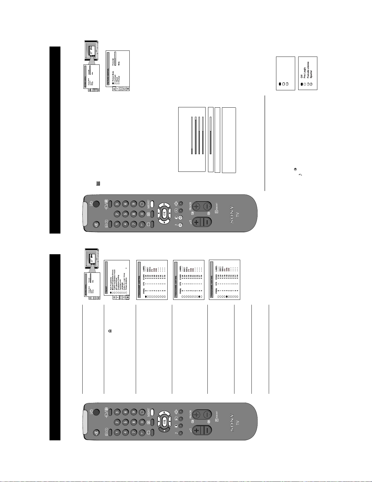
Adjusting the picture
Additional TV Features
Although the picture is adjusted at the factory, you can modify it to suit your own taste.
b button to confirm. For a
Movie (for films)
screen.
Picture Mode Picture Modeb Personal (for individual settings)
B Live (for live broadcasts)
Brightness*
Colour*
Sharpness*
Hue**
Scroll
Auto 16:9 b Off B On
Changing picture and sound modes quickly
You can quickly change the Picture Mode or the Sound Mode
without entering the ‘PICTURE CONTROL’ or the ‘SOUND
Contrast
Reset Resets picture to factory preset levels
Format Format (refer to page 15 for details)
*Only if you select ‘Personal’ in ‘Picture Mode’.
** Available for NTSC colour system only.
CONTROL’ menu screens.
V or v buttons to select the desired mode.
or the symbol for sound modes.
2. Press the
screen.
3. Press the OK button to remove the display from the TV
1. Press the symbol on the remote control for picture modes
b button to confirm.
V or v buttons on the remote control to select the
V or v buttons to select the item on the screen you
symbol on the menu screen then press the
menu on the TV screen.
1. Press the MENU button on the remote control to display the
2. Press the
wish to adjust then press the
description of the menu items and their effects, see the table
enter the ‘PICTURE CONTROL’ menu.
below.
3. Press the
b or B buttons to adjust your selected item.
V or v buttons to select the item on the screen you wish to
adjust then press the
5. Press the
4. If you selected ‘Picture Mode’ or ‘Format’ in step 3, press the
B button to return to the ‘PICTURE CONTROL’ menu.
store the new setting.
8. Repeat steps 3-7 to adjust the other items.
6. As soon as you have adjusted the item, press the OK button to
9. Press the MENU button to remove the menu from the TV
7. If you selected ‘Picture Mode’ or ‘Format’ in step 3, press the
12
11
Additional TV Features
Re-arranging the TV channels
After tuning the TV, you can use this feature to change the channel order.
button to enter the
b
buttons to select the symbol on the
v
or
V
the menu on the TV screen.
1. Press the MENU button on the remote control to display
2. Press the
menu screen then press the
‘PRESET’ menu.
button to select ‘Programme Sorting’ then
v
3. Press the
button to enter the ‘PROGRAMME
b
SORTING’ menu.
press the
buttons to select the channel you want
v
or
V
4. Press the
to move then press the OK button to confirm.
buttons to select the new programme
v
or
V
position (eg PROG 4) for your selected channel then
5. Press the
press the OK button to confirm. The selected channel
now moves to its new programme position.
6. Repeat steps 4 and 5 if you wish to sort other c hannels.
screen.
7. Press the MENU button to remove the menu from the TV
10
b button to
Additional TV Features
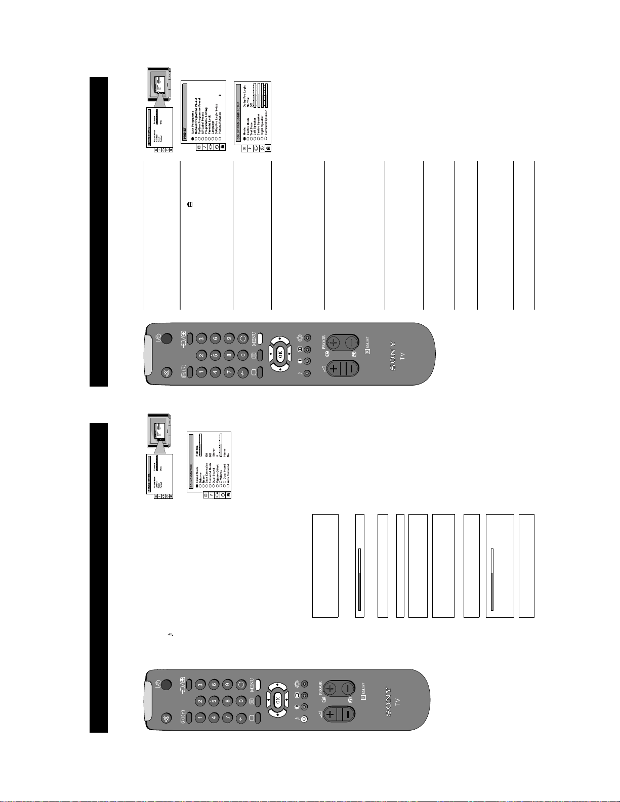
Setting up Dolby Pro Logic
Before listening to Dolby Pro Logic encoded programmes, you can adapt the Dolby features to suit your own taste. Normally this
is only required when you install the TV and the speakers, or when changing the speaker positions.
b button to enter the
b or B buttons to select ‘On’,
b button to confirm. The tone remains at the left
the menu on the TV screen.
1. Press the MENU button on the remote control to display
menu screen then press the
‘PRESET’ menu.
2. Press the V or v buttons to select the symbol on the
Setup’ on the menu screen then press the
enter the ‘DOLBY PRO LOGIC SETUP’ menu.
3. Press the V or v buttons to select ‘Dolby Pro Logic
4. Press the V or v buttons to select ‘Mode’, then press the
b button to enter. Press the b or B buttons to select one
of the following modes then press the OK button to store
the chosen mode:
Dolby Pro Logic: all 5 speakers are activated
b button to enter. Press the b or B buttons to select one
Dolby 3 stereo: surround speakers are not used
of the following modes then press the OK button to store
the chosen mode:
Normal: all 5 speakers are activated
Wide: wider bandwidth for centre speaker
5. Press the v button to select ‘Centre Mode’, then push the
Phantom: centre speaker is not used
then press the OK button.
The test tone will cycle through all the speakers.
button to enter. Press the
6. Press the v button to select ‘Test Tone’ then push the b
speaker.
the
7. Press the v button to select the ‘Left Speaker’, then press
‘Right’, and ‘Surround’ speakers, so that the sound output
from all speakers are balanced in relation to your sitting
position.
press the OK button.
8. Press the b or B buttons to alter the sound level, then
9. Repeat steps 7 and 8 to select and adjust the ‘Centre’,
TV screen.
10.Press the MENU button to remove the display from the
14
13
button
b
button to confirm.
b
buttons on the remote control to select
buttons to select the item on the screen
v
v
or
or
V
V
the menu on the TV screen.
the symbol on the menu screen then press the
you wish to adjust then press the
For a description of the menu items and their effects, see
2. Press the
to enter the ‘SOUND CONTROL’ menu.
3. Press the
1. Press the MENU button on the remote control to display
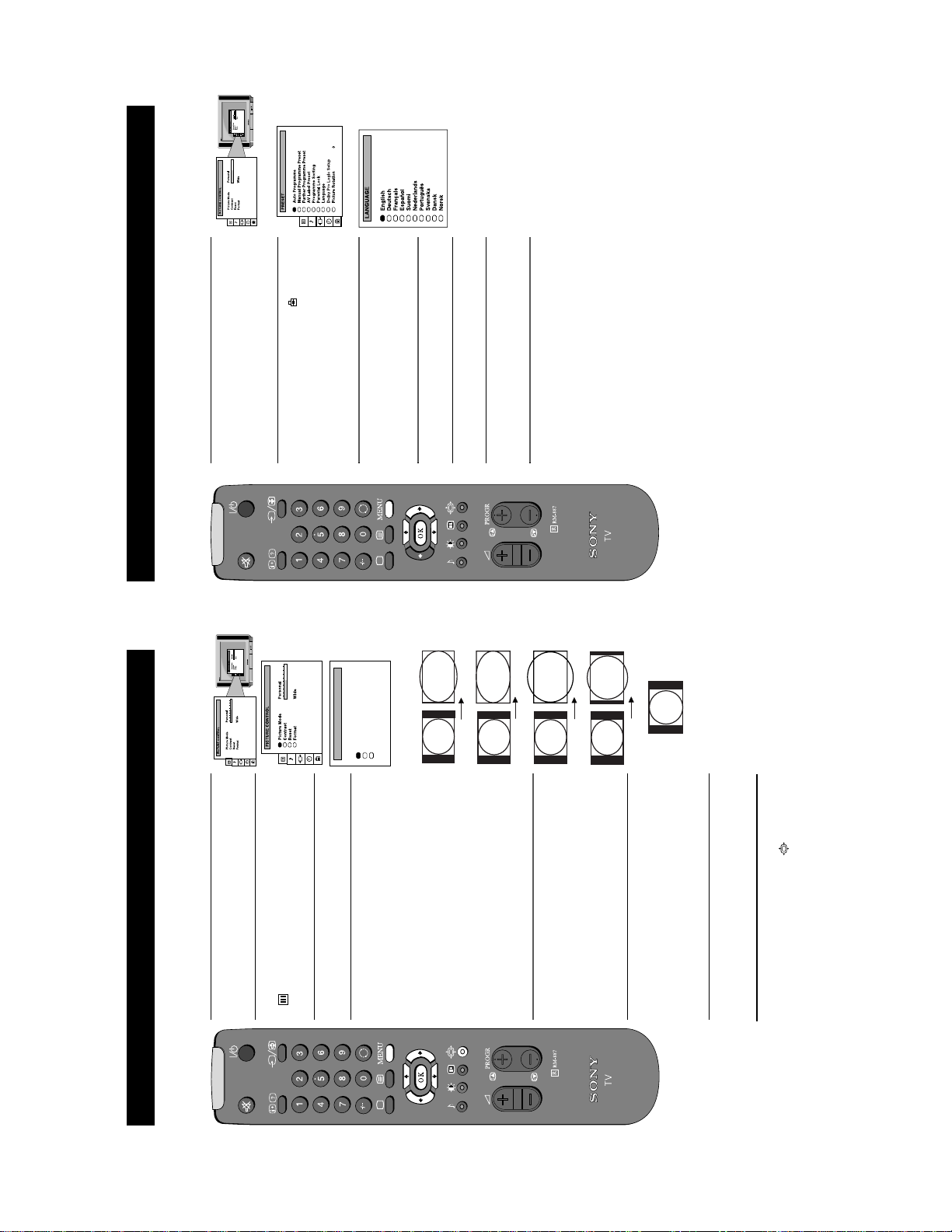
Adjusting the sound
Additional TV Features
Although the sound is adjusted at the factory, you can modify it to suit your own taste.
button to confirm.
b
buttons to adjust your selected item.
buttons to select the item on the screen
B
v
or
or
b
V
you wish to adjust then press the
the table below.
press the
4. If you select ‘Sound Mode’ or ‘Surround Mode’ in step 3,
5. Press the
button to return to the ‘SOUND
B
button to store the new setting.
step 3, press the
6. As soon as you have adjusted the item, press the OK
CONTROL’ menu.
7. If you selected ‘Sound Mode’ or ‘Surround Mode’ in
8. Repeat steps 3-7 to adjust the other items.
9. Press the MENU button to remove the menu from the TV
screen.
Jazz
Rock
B Pop
In ‘Personal’ mode, Treble an d Bass can be adjus ted
Only available when ‘Surround Mode’ is set to ‘Off’
Sound Mode b Personal
Balance
Reset Resets sound to factory preset levels
Pro Logic--> Pseudo Stereo--> Spatial--> off
Bass Extension Boosts bass by a fixed amount
Surround Mode Choose from the special sound effects:
(for a bilingual broadcast)
A for channel 1 B b B for channel 2
Dual Sound Stereo BbMono (for a stereo broadcast)
adjusted over a range of -12 to +12.
Volume Offset B The channel volume level can be b
Headphones
i Volume
i Dual Sound Stereo B b Mono (for a stereo broadcast)
(for a bilingual broadcast)
A for channel 1 B b B for channel 2
Surround sound when transmitted.
Auto Surround Set to ‘On’ to automatically select Pro Logic
11
9
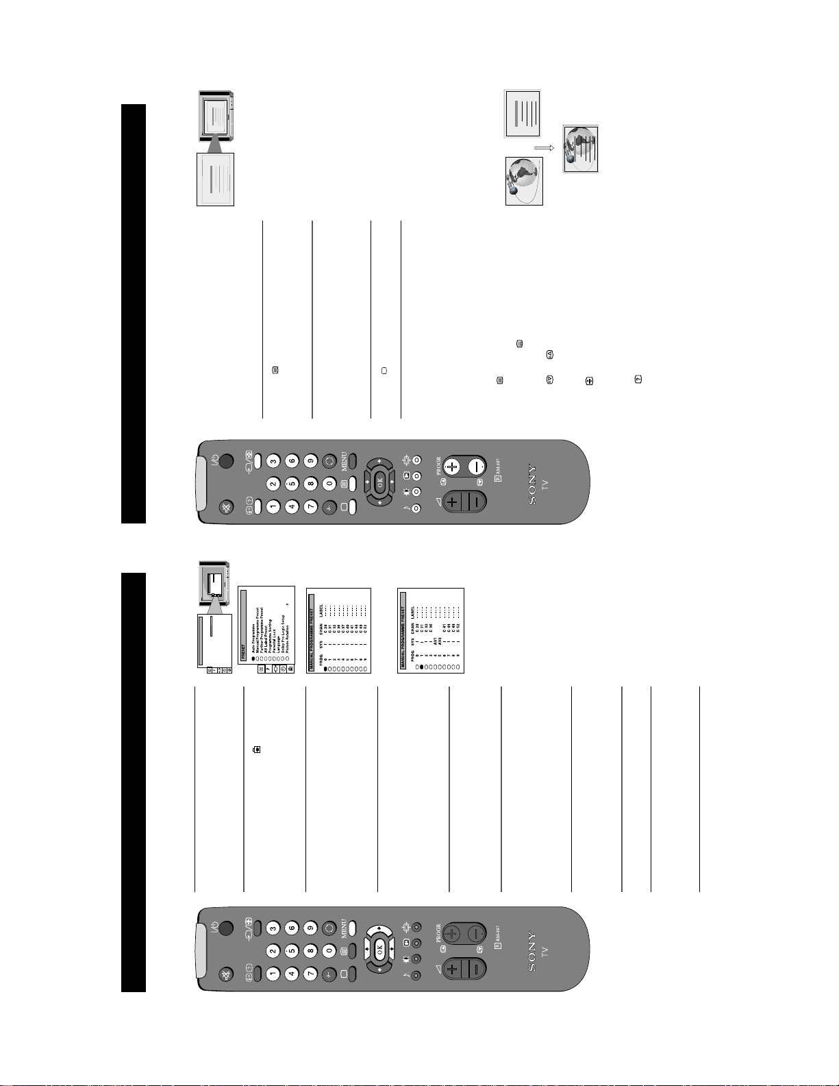
Choosing a language for the TV menu screens
Additional TV Features
button to enter the
b
buttons to select the symbol on the
v
or
V
the menu on the TV screen.
1. Press the MENU button on the remote control to display
The TV consists of a menu system which can appear on screen in a variety of languages. Use the following feature to select the
language that best suits you.
2. Press the
menu screen then press the
‘PRESET’ menu.
buttons to select ‘Language’ on the
v
or
V
3. Press the
button to enter the
b
menu screen then press the
‘LANGUAGE’ menu.
buttons to select your chosen language.
v
or
V
4. Press the
TV screen.
5. Press the OK button to confirm your selection.
6. Press the MENU button to remove the display from the
15
Wide 0On
4:3
b
FORMAT
Format
Scroll
Auto 16:9
Smart
rmat
b
Wide
Zoom
14:9
button to
buttons to select ‘Scroll’. You can use
v
or
V
Press the
buttons to
b
B
or
b
buttons to select ‘On’ if you
B
or
b
buttons to select ‘Auto 16:9’ then press the
v
or
V
adjust the value over a range of -5 to +5. Press the OK button
Press the
to store.
wish the TV set to switch automatically to Wide format if a
button to enter. Press the
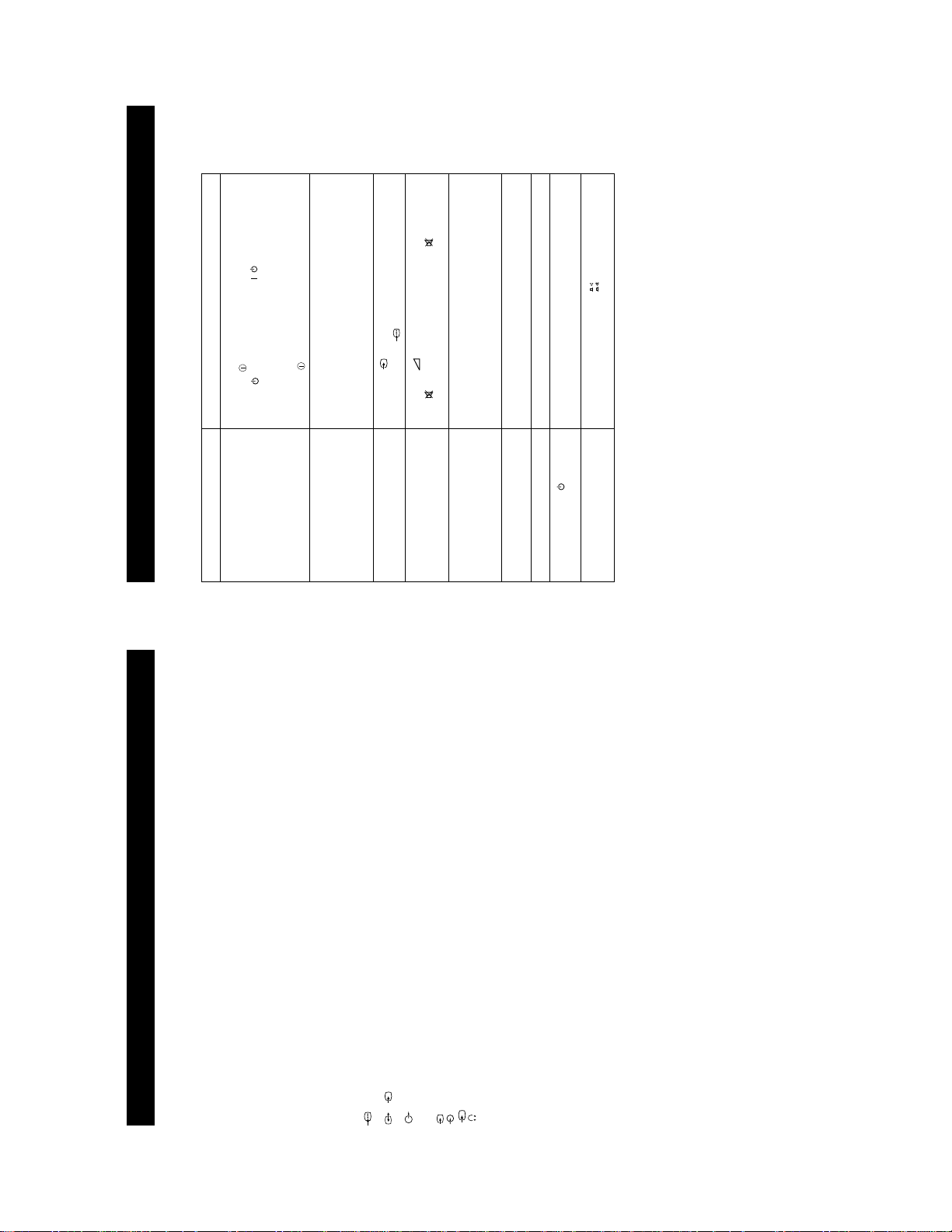
6. Auto 16:9
‘Scroll’ to move the screen up or downwards in order to see
the cut-off parts (eg to read subtitles). Press the
highlight the present value then press the
16:9 broadcast is detected or ‘Off’ to retain the format selected
in step 4. Press the OK button to store.
7. Press the MENU button to remove the menu from the TV
screen.
Note: You can change the picture format quickly without having
to enter the menu system. Simply press the button repeatedly
until the picture is displayed in the format you desire.
button to
b
buttons repeatedly to select
B
or
button to enter the ‘FORMAT’ menu.
b
buttons on the remote control to select the
v
or
V
menu on the TV screen.
1. Press the MENU button on the remote control to display the
2. Press the
Changing the screen mode
Additional TV Features
Using this Screen Mode feature you can change the aspect ratio of the screen.
symbol on the menu screen then press the
buttons to select ‘Format’ on the menu
v
or
V
enter the ‘PICTURE CONTROL’ menu.
screen then press the
3. Press the
b
buttons to select ‘Format’ then press the
v
or
V
Press the
one of the following modes then press the OK button to store
the chosen mode:
broadcasts
broadcast in cinemascopic format
button to enter. Press the
4. Format
• Smart - imitation of wide screen effect (16:9) for 4:3
• Wide - for 16:9 broadcasts
conventional 14:9 picture
• Zoom - imitation of wide screen effect (16:9) for movies
• 14:9 - compromise between 4:3 and 16:9 format - for
5. Scroll (Applies to Zoom, 14:9 or Smart format only)
• 4:3 - conventional 4:3 picture
12
TELETEXT
25
153
101
98
TELETEXT
Index
Programme
News
Sport
Weather
25
153
101
TELETEXT
Index
Programme
News
Sport
25
153
101
98
TELETEXT
TELETEXT
Index
Programme
News
Sport
Weather
98
Weather
25
153
101
TELETEXT
TELETEXT
Index
Programme
News
Sport
98
Weather
1. When viewing channels, press a number button on the
Teletext
Additional TV Features
Teletext is an information service transmitted by most TV stations.
. . . . . . . . .
Wide
Personal
Picture Mode
Contrast
Reset
FormatFormat
PICTURE CONTROL
. . . . . . . . .
Wide
Personal
Picture Mode
Contrast
Reset
FormatFormat
PICTURE CONTROL
2. Press the button on the remote control to switch on
button to enter the PRESET
b
Switching Teletext on and off
teletext.
3. Input the three digits of the page number you require
using the numbered buttons on the re mote control. If you
button to enter
b
make a mistake, type in any three digits to complete the
number then re-enter the correct page number.
4. Press the button to switch off teletext.
Note: Teletext errors may occur if the broadcasting
Using Other Teletext Functions
To superimpose Teletext on to the TV
Press the button on the remote control once in teletext
mode or twice in TV mode to superimpose teletext on to the
TV screen. Press the button once more to cancel.
To move to the next or preceding page
Press the or buttons to select the previous or next
page.
To freeze a Teletext page
Press the button to freeze the page. Press again to cancel
the freeze.
Revealing concealed information (eg:answers to a
quiz).
Press the button to reveal information. Press again to
conceal the information.
Using colour buttons to access pages (Fastext)
(only available if the TV station broadcasts Fastext signals)
When the colour coded menu appears at the bottom of a page,
press the colour button (green, red, yellow or blue) on the
control to access the corresponding page.
22
19
b
b
buttons on the
v
or
V
remote control to select the channel which carries the
signals are weak.
teletext service you wish to receive.
Additional TV Features
Manually tuning the TV
You have already tuned the TV automatically using the instructions at the start of this manual. You can however carry out this
operation manually, adding channels to the TV, one at a time.
buttons to select the symbol on the
v
or
V
the menu on the TV screen.
1. Press the MENU button on the remote control to display
TV screen then press the
2. Press the
buttons to select ‘Manual Programme
v
or
V
menu.
Preset’ on the menu screen then press the
the ‘MANUAL PROGRAMME PRESET’ menu.
3. Press the
buttons to select a programme number for
v
or
V
4. Press the
your channel (eg PROGR 1 for BBC1) then press the
button to enter.
buttons to select the TV broadcast system
v
or
V
5. Press the
or a video input source (AV1, AV2 ...) then press the
button to confirm.
buttons to search for the next available
v
or
V
second number digit of ‘CHAN’ with the number buttons
on the remote controlorPress the
6. Select the first number digit of ‘CHAN’ (channel) then the
channel.
number you selected, press the
7. If you do not wish to store this channel on the programme
button.
press the MENU button to remove the menu from the TV
remote control to continue searching for the desired
channel.
8. If this is the channel you wish to store, press the OK
screen.
9. Repeat steps 4-8 if you wish to store more channels, then
13
27
/
button on the remote control.
using the button on the front of the TV.
Adjustment display. Adjust the brightness, picture and colour
balance levels.
the factory settings.
the RGB symbol is displayed on the screen.
remote control.
display and adjust the colour setting.
the factory settings.
• If is displayed on the screen, press the button on the
• From the Picture Adjustment display select Res et to return to
• Turn off any equipment connected to the scart connectors on
• Press the button on the front of the TV.
the rear of the TV.
• If the indicator is on press the button or a numbered
• Check the aerial connection.
• Turn the TV off for 3 or 4 seconds and then turn it on again
• Using the MENU system, select the Picture
• From the Picture Adjustment display select Res et to return to
• Press the button repeatedly on the remote control until
• Press the button on the remote control.
• Contact your nearest Sony service centre.
not pressed in.
• Check that the button marked on the rear of the TV is
Troubleshooting
Additional Information
Problem Solution
Here are some simple solutions to problems which may affect the picture and sound.
No picture (screen is dark), no sound • Plug the TV in.
Poor or no picture (screen is dark), b ut
good sound.
Poor picture quality when watching
an RGB video source.
Good picture, no sound
No colour on colour programmes • Using the MENU system, select the Picture Adjustment
Distorted picture when changing
programmes or selecting T elet ext
Remote control does not function • Replace the batteries.
The standby indicator on the TV
flashes
No Sound
• If you continue to have these problems, have your TV serviced by qualified personnel.
• NEVER open the casing yourself.
Specifications
Additional Information
TV systemIColour system
Audio outputs - phono jacks
Video input -phono jacks
Audio inputs - phono jacks
S video input - 4 pin DIN
21-pin Euro connector (CENELEC standard) including audio/video
input, RGB input, TV audio/video output.
input, S-video input, Monitor audio/video output.
2
s
/ 21-pin Euro connector (CENELEC standard) including audio/video
2
PAL
NTSC 3.58, 4.43 (only Video In)
Channel coverage
UHF:B21-B69
Picture tube
1
FD Trinitron WIDE
Approx 71cm (28inches) (Approx 66cm picture measured diagonally), 102° deflection
Rear Terminals
Headphones jack - minijack stereo
s
3
3
Front Terminals
Sound output
Left/Right: 2x20W (music power)
Sub woofer: 20W (music power)
Centre 1x10W (music power)
Surround 2x5W (music power)
Power consumption
123W
Dimensions (wxhxd)
Approx. 761x496x525mm
Weight
Approx. 44.0kg
Accessories supplied
RM-887 remote control (1)
IEC designated size AA battery (2)
Centre speaker (1)
Surround speaker (2)
Other features
Teletext, Smartlink
Design and specifications are subject to change without notice.
26
14
1 Clip bracket into Beznet
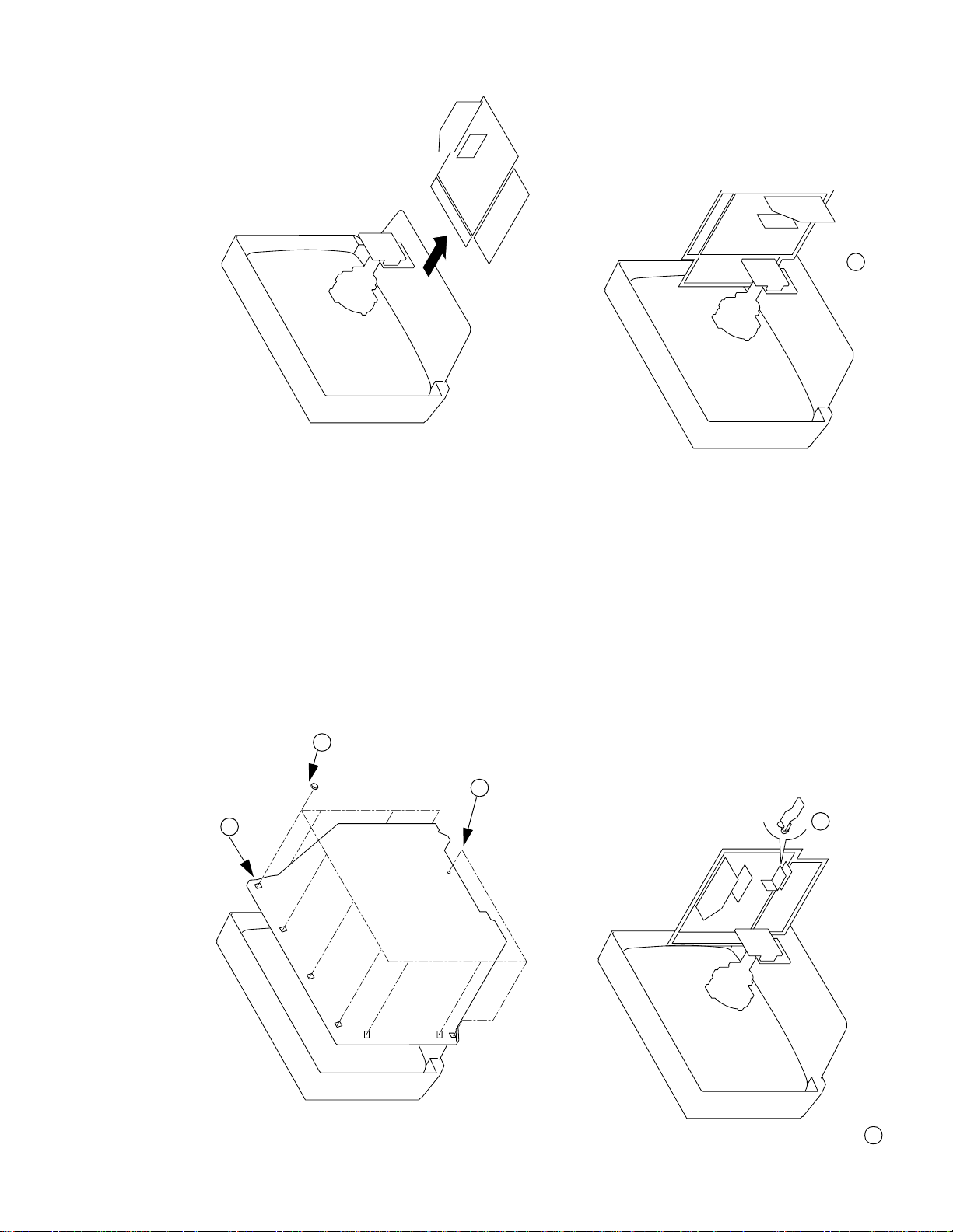
SECTION 2
DISASSEMBLY
2-2. CHASSIS ASSY REMOVAL
2 8 Screws
(BTVTP 4x16)
1 1 Screw (BTVP 4x16)
3 Rear Cover
2-3-2. SERVICE POSITION (2) 2-3-1. SERVICE POSITION (1)
2 Insert into heatsink
2-1. REAR COVER REMOVAL
1 Snap off from main bracket
15
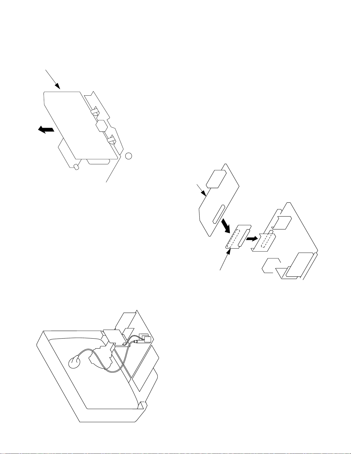
A Board
1 Remove CN301 before removing A board
2-5. A BOARD REMOVAL
A board
2-6. A EXTENSION BOARD
BE-3E Extension Board
2-4. WIRE DRESSING
16
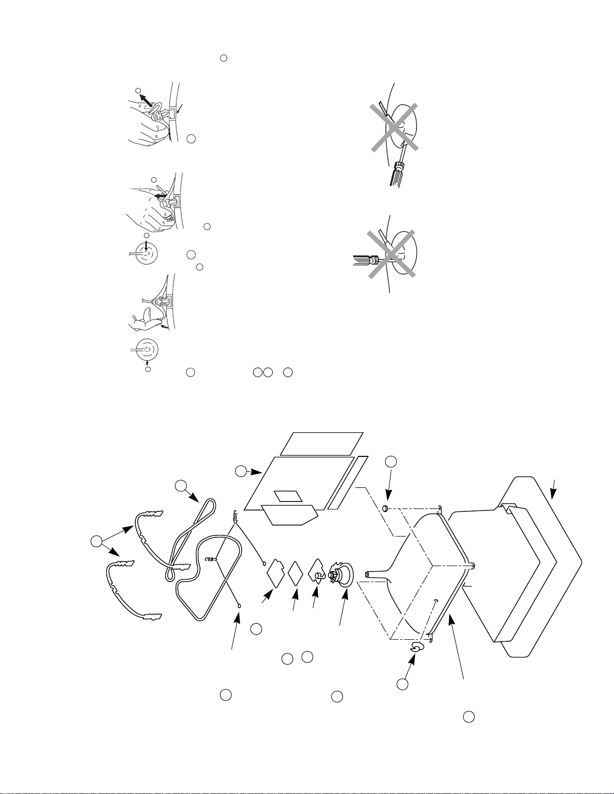
• REMOVAL OF ANODE-CAP
c
b
a
Note : Short circuit the anode of the picture tub e and the anode cap to the metal chassis, CRT
* REMOVING PROCEDURES.
shield or carbon paint on the CRT, after removing the anode.
Anode button
3 When one side of the rubber cap is
separated from the anode button, the
anode-cap can be removed by turning
up the rubber cap and pulling it up in
the direction of the arrow c
b
2 Using a thumb pull up the rubber cap
firmly in the direction indicated by the
arrow b
anode connector.
Do not turn the rubber foot over excessively this may cau s e da mage if the shatter
hook sticks out.
Turn up one side of the rubber cap in
the direction indicated by the arrow a
1
• HOW TO HANDLE THE ANODE-CAP
1 To prevent damaging the surface of the ano de-cap do not use sharp materi al s.
2 Do not apply too great a pressure on the rubber, as this may cause damage to the
3 A met al fitting called a shatter hook t erm inal is fitted inside the rubber cap.
2 Chassis assy
10 Four PT screws
Cushion
8 Degaussing coils
7 DGC holders
3 C board
5 Neck assy
4 VM Board
9 Spring Extension
6 Deflection yoke
Anode cap
1
11 Picture tube
2-7. PICTURE TUBE REMOVAL
17
4
4
Fig 4
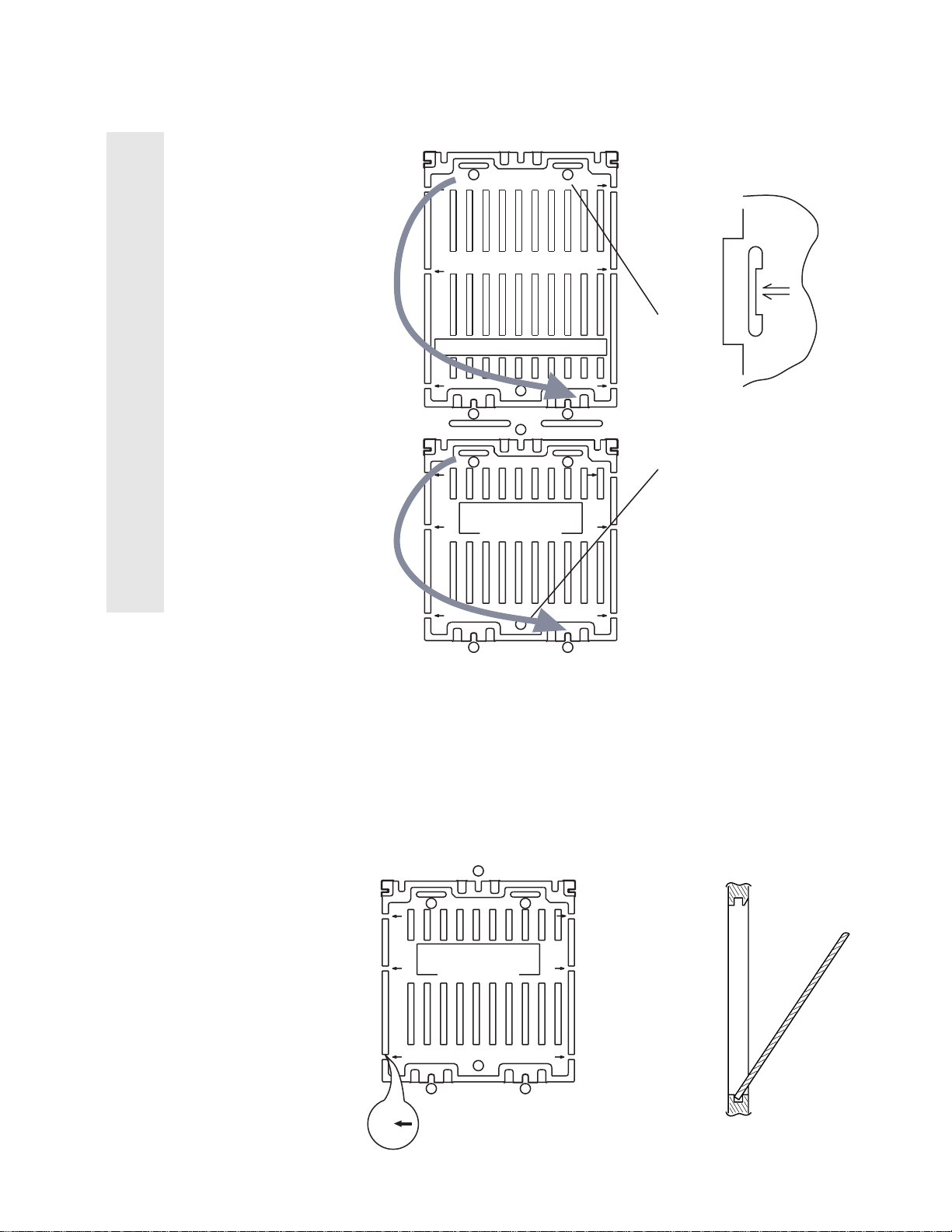
AFTER CUTTING AWAY FOR THE SAFETY REASON.
THIS PLATE MUST BE REMOVED
3
44
1
For safety reasons, on no account should the plates be
removed and not refitted after servicing.
£
(2) REFITTING THE PLATES
2
chassis. See Fig 2.
other.
Because the plates differ in size it is important that the correct plates are refitted in
their original location.
The plates are identified by numerical markings on their top side e.g. 1,2
1. Identify the plate by locating its marking.
2. Rotate the plate through 18 0 ’ (do not flip over).
3. Locate the corresponding numerical markings indicated on the main
4. Refit the plate as indicated in Fig 3 with the markings located next to each
REFITTING REFITTING
1
1
2
FOR SAFETY REASONS
AFTER CUTTING AWAY
(TURN 180' NOT FLIP OVER)
ATTENTIONATTENTION
2
2
THIS PLATE MUST BE REMOVED
22
NUMERICAL MARKINGS
Fig 2
In the event of the plates requiring to be removed
at a later stage, this can be achieved by inserting a
screwdriver in the snap-recess indicated as in Fig 4
and lifting out.
REMOVAL AND REPLACEMENT OF THE MAIN-BRACKET
BOTTOM PLATES.
(1) REMOVING THE PLATES
FOR SAFETY REASONS
AFTER CUTTING AWAY
(TURN 180' NOT FLIP OVER)
THIS PLATE MUST BE REMOVED
ATTENTIONATTENTION
MAIN BRACKET
FIG 3
1
22
Only remove the necessary plate to gain access to the printed wiring board.
In the event of servicing being required to the solder side of the D Board printed
wiring board, the bottom plates fitted to the main chassis bracket require to be
removed.
This is performed by cutting the gates with a sharp wire cutter at the locations
indicated by arrows.
Note :There are 4 plates fitted to the main br acket and secured by 6 gates.
Cut points
Fig 1
INSERT FROM
THE BOTTOM
SIDE
18
SECTION 3
SET-UP ADJUSTMENTS
• When complete readjustment is necessary or a new
picture tube is installed, carry out the following
adjustments.
• Unless t here are specific instructions to the contrary,
carry out these adjustments with the rated power supply.
• Unless t here are specific instructions to the contrary, set the
controls and switches to the following settings:
Contrast ............... normal
Brightness ............... normal
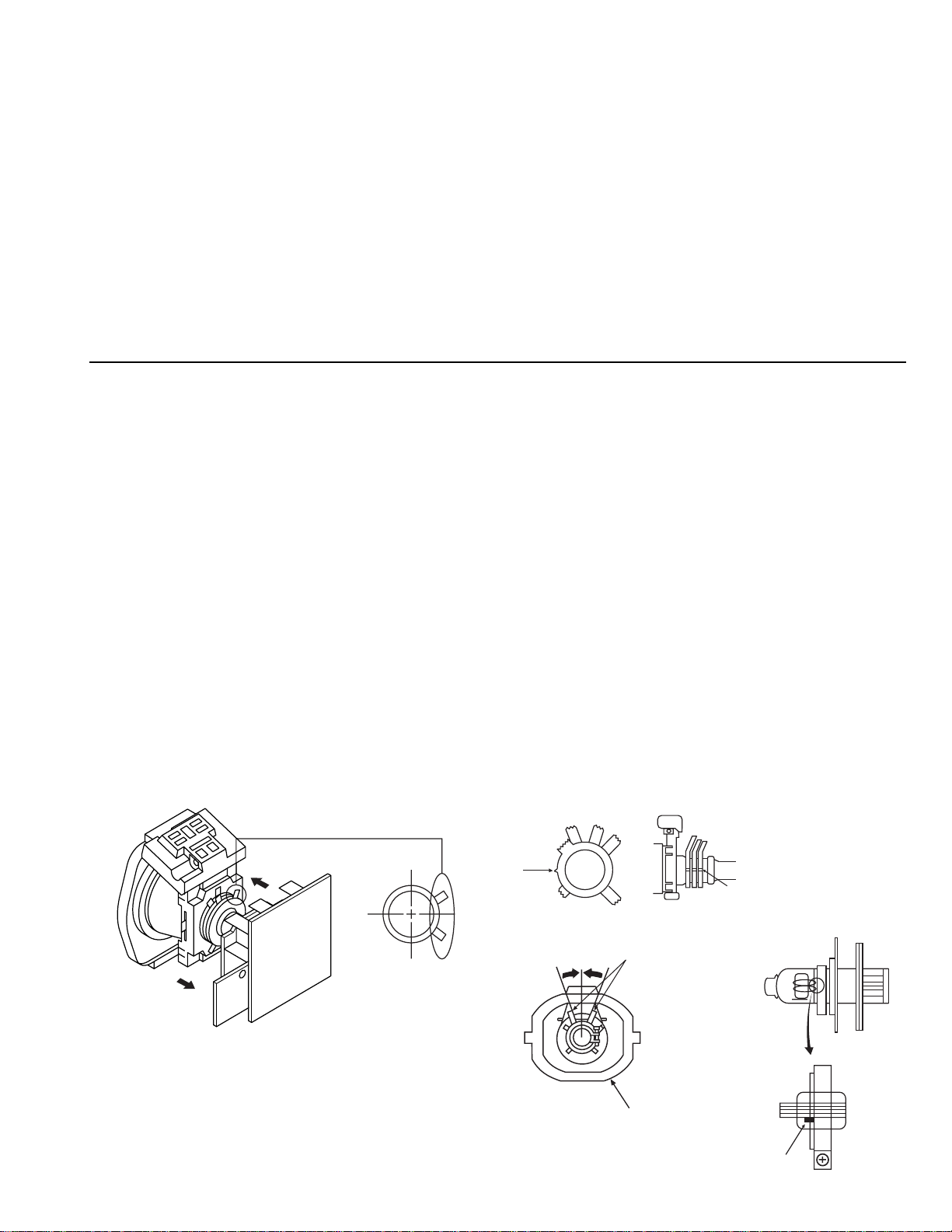
3-1.BEAM LANDING
Preparation:
1. In order to reduce the influence of geomagnetism on the set’s
picture tube, face it in an easterly or westerly direction.
2. Switch on the set’s power and degauss with the
degausser.
(1) Adjustment of Correction Magnet for Y-Splitting
Axis
1. Input a crossha tch signal from the pattern generator.
2. Set the Pictur e control to minimum and confirm that the
Brightness control is set to normal.
3. Position the neck assembly as indicated in Fig.3-2.
4. Move the deflection yoke as far forward as is possible.
5. Adjust the up per and lower pin symmetricall y by opening or
closing the Y-splitting axis correction magnets located on the
neck assembly.
6. Return the deflection yoke to its original position.
Carry out the following adjustments in this order:
3-1. Beam Landing
3-2. Convergence
3-3. Focus
3-4. White balance
Note: Test equipment required
1. Color bar/pattern gener a tor.
2. Degausser.
3. Digital multimeter.
4. Oscilloscope.
(2) Landing
Note :Before carrying out the following adjustments
adjust the magnets as indicated below [See Fig.3-3].
1. Input an all-white signal from the pattern generator.
Maximize the picture setting and adjust the Brightness
setting.
2. Rough-adjust the foc us and horizontal convergence.
3. Loosen the deflection yoke screws and alig n the purity
adjustment knob to its central position. [See Fig.3 -1].
4. Switch from the all-white pattern to an all-green pattern.
5. Move the deflection yoke backwards and adjust with the
purity magnet so that the green is at the centre and it aligns
symmetrically. [See Fig.3-4].
6. Move the deflection yoke forward and adjust so that the
entire screen becomes green.
7. Switch the raster signal to red, then to blue and verify the
landing condition.
8. When the position of the d efl ect ion yo ke has be en d eter mined,
fasten the deflection yoke with the screw.
9. If the beam does not land correctly in all the corners of the
screen, use magnets to correct it. [See Fig.3-5].
Y-splitting axis correction magnet
Caution :
High voltages are present on the Deflection yoke terminals take care when handling the Deflection yoke whilst carrying
out adjustments.
19
Purity
Fig.3-1
Deflection yoke
Align the bottom edge
of the neck assy with
the G3 hole centre.
Fig.3-3
Align Pips
on each
magnet
Neck a s sy
Fig.3-2
Purity control corrects
this area.
Disk magnets or
rotatable disk
magnets correct
these areas (a-d).
Deflection yoke positioning
corrects these areas
Center dot
GREEN
BLUE
RED
Fig.3-4
H.STAT
convergence
V.STAT
vertical static magnet
control
H.STAT VR on
mount side
H.STAT convergence
• If the horizon tal dots are unable to coincide with the variable
range of the H.STAT convergence, adjust together with the
V.STAT convergence while tracking.
[Adjust the convergence by tilting the V.STAT convergence or
by opening and closin g the V.STAT convergence.]
(Open)
(Close)
4. Movement of the red, green and blue dots by tilting the
V.STAT magnet and by opening or closing the V.STAT
magnet.
Fig. 3-5
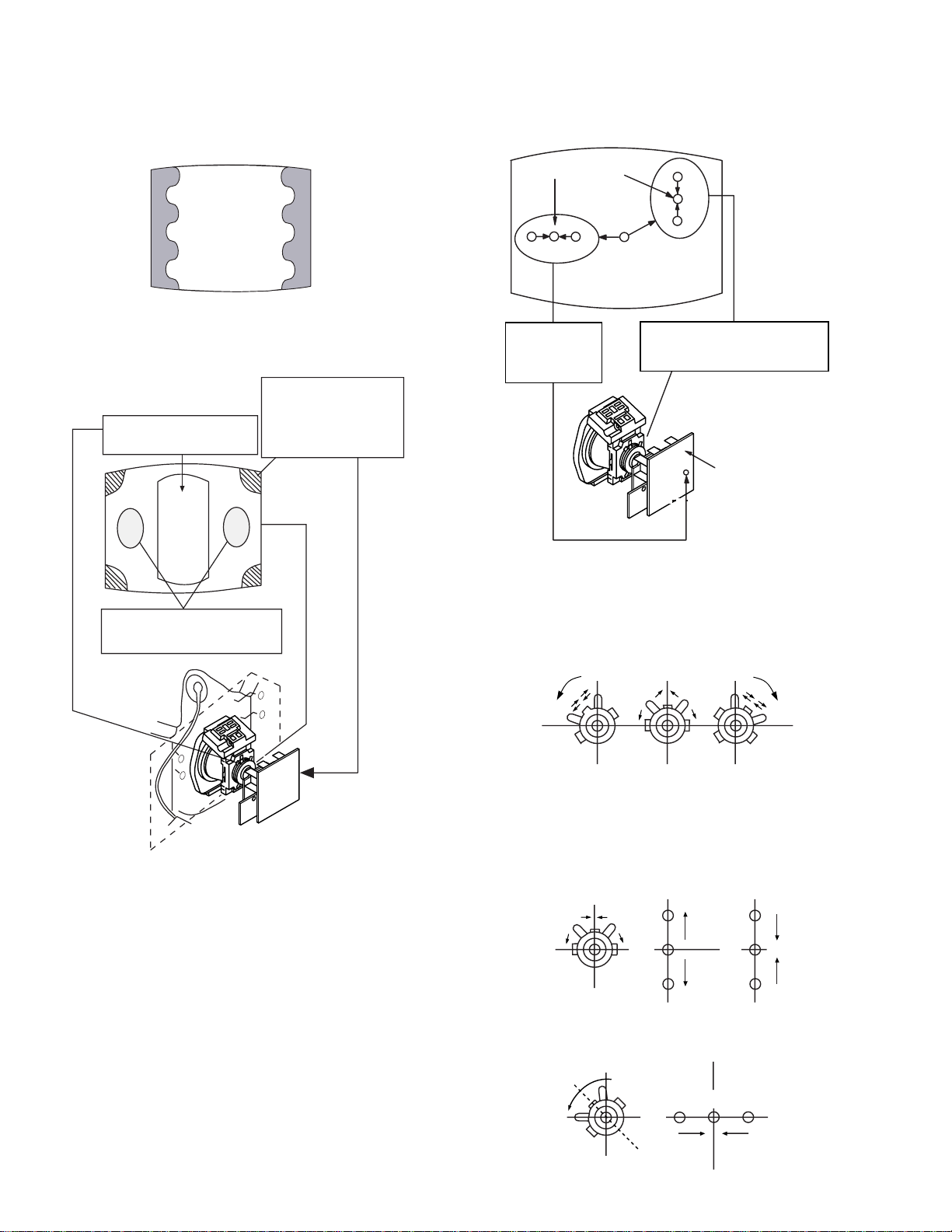
3-2.CONVERGENCE
(1) Screen centre convergence
[Static convergence]
1. Input a dot signal from the pattern generator.
Normalize the picture setting.
2. [Moving horizontally], adjust the H.STAT control so that the
horizontal red, green and blue dots coincide at the centre of the
screen.
3. [Moving vertically], adjust the V.STAT magnet so that the
vertical red, green and blue dots coincide at the centre of the
screen.
a). By opening or closing the V.STAT magnet, the red, green and
blue dots move as indicated below.
B
G
R
B
G
R
b). By rotating the V.STAT magnet counter clockwise, the red,
green and blue dots move as indicated below .
B
GR
20
c). By rotating the V.STAT magnet clockwis e, the red, green and
blue dots move in the direction indicated below.
B
GR
HAMP
d). By opening or closing the V.STAT magnet, the red, green and
blue dots move in the direction indicated below.
R
G
Note : If the blue dot does not coincide with the red and
green points correct the points by using the BMC
[Hexapole] magnet.
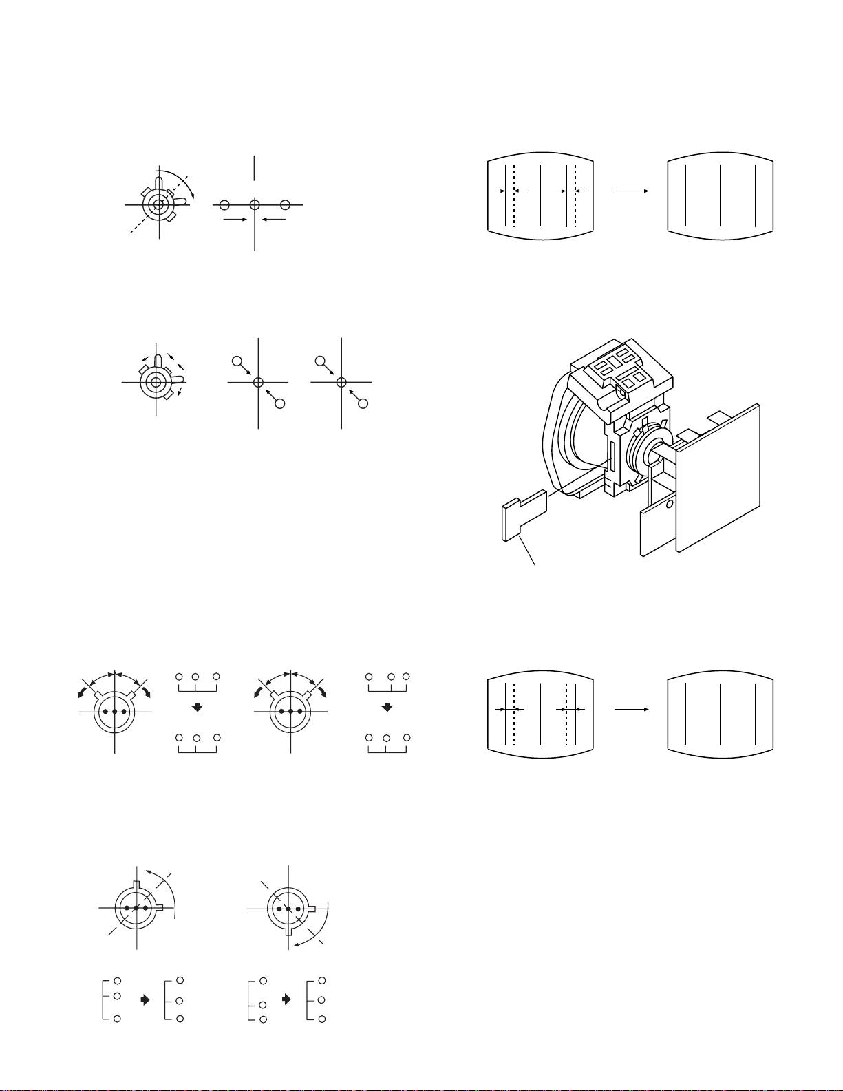
5. Correction for HMC [horizontal mis-convergence] and
VMC [vertical mis-convergence] by using the BMC
[Hexapole] magnet.
a). HMC cor rection by BMC [Hexapole] ma gnet and movement
of the electron beam.
HMC correction(A) HMC correction(B)
A < B
RG B
B
G
A > B
R
RGB
B
6. HTIL correction can be performed by adding a THL correction
ASSY to the DY.
TLH correction Assy
4-057-714-01
HTIL
A = B
RG B
b). VMC correction by BMC [Hexapole] magnet and movement
of the electron beam.
VMC correction(A) VMC correction(B)
C < D
C
D
C = D C > D C = D
R
G
B
R
C
G
D
B
R
G
B
A = B
R
G
B
RG B
21
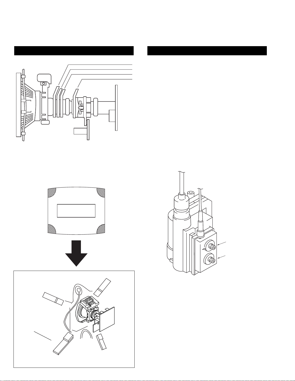
3-3.SCREEN (G2)
Y-splitting axis correction magnet
V STAT convergence magnet
BMC (Hexaploe) magnet
Purity magnet
LAYOUT OF EACH CONTROL SCREEN G2 ADJUSTMENT
1. Input a dot signal from the pattern generator.
2. Set the Picture, Brightness and Colour to minimum.
3. Apply 175V DC from an external power supply to the
R, G and B cathodes of the CRT.
4. Whilst watching the picture, adjust [SCREEN G2] located on
the FBT [flyback transformer] to the point just before the
flyback return lines disappear.
3-4.FOCUS
1. Receive a television broadcast signal.
2. Normalise the picture setting.
3 Adjust the focus control located on the FBT [flyback
transformer] to obtain the best focus at the centre of the screen.
Bring only the centre area of the screen into focus, the
magenta-ring appears on the screen. In this case, adjust the
Fig 3-6
Note : If you are unable to adjust t he corner convergence
properly, this can be corrected with the use of
permalloys.
focus to optimize the screen uniformly.
Permalloy Assy
X-4387-214-1
a
a-d: screen-corner
convergence defect
c
b
d
FOCUS
SCREEN (G2)
Convergence adjustment with permalloy.
22

3-5. WHITE BALANCE
WHITE BALANCE ADJUSTMENT
1. Input an all white signal from the pattern generator.
2. Enter into the Service Mode.
3. Enter into the ‘Picture Adjustment’ service menu.
4. Select ‘Sub contrast’ and adjust to 7.
5. Select the ‘Green drive’ and adjust so that the white balance
becomes optimum.
6. Select the ‘Blue drive’ and adjust so that the white balance
becomes optimum.
7. Press the ‘TV’ button on the remote commander to return to
TV operation.
PICTURE ADJUSTMENT
AFC mode 1
REF position 2
SCP BGR 1
SCP BGF 1
Trap fo 0
Sub contrast Adj
Sub colour Adj
Sub brightness Adj
Sub hue Adj
Green drive Adj
Blue drive Adj
Green cutoff Adj
Blue cutoff Adj
Gamma 0
Pre / overshoot 3
Y delay 3
23
 Loading...