

Sony kv 28fq86b schematic
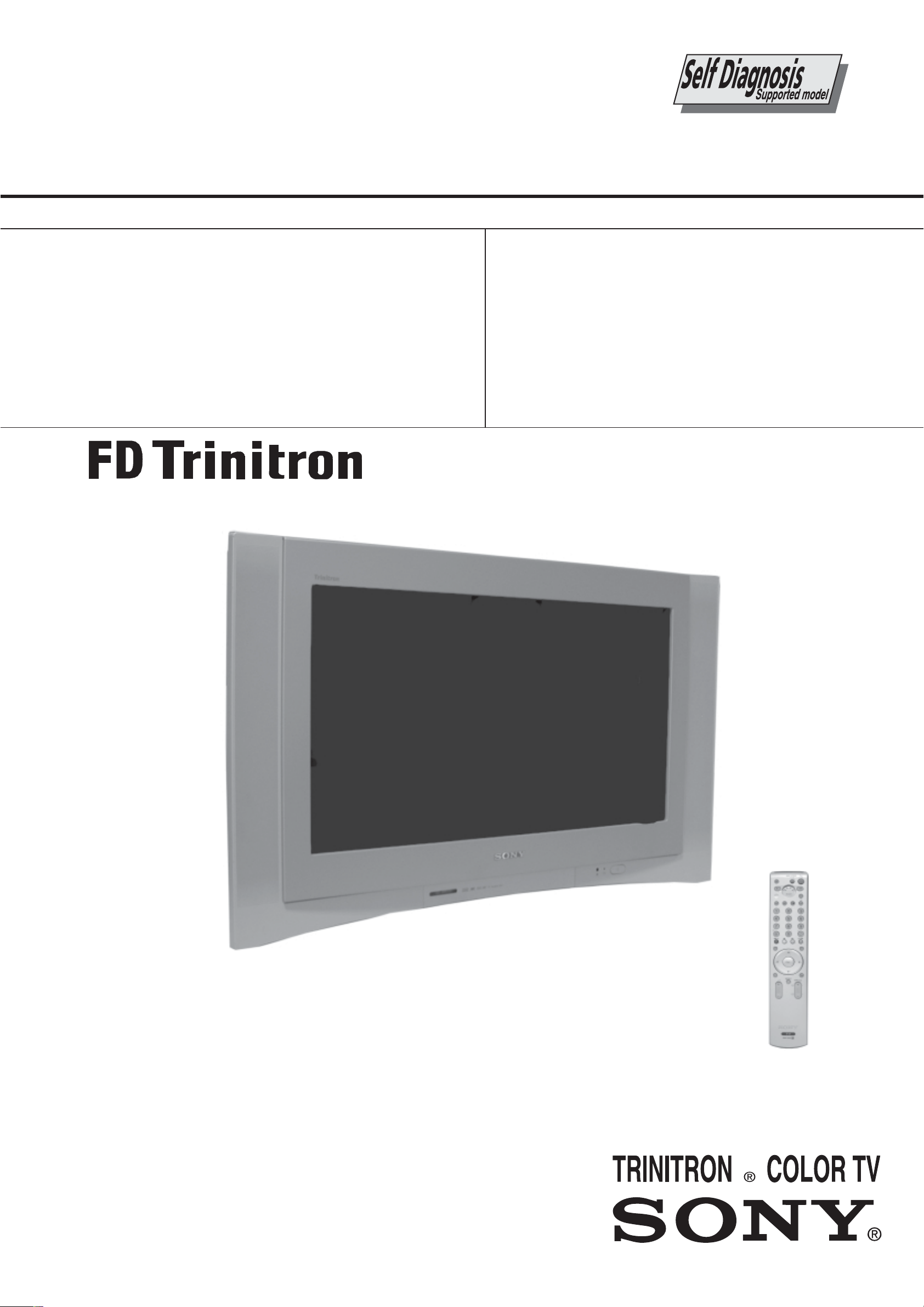
SERVICE MANUAL
AE-6BA
CHASSIS
MODEL
KV-28FQ86B
KV-28FQ86E
COMMANDER DEST CHASSIS NO.
RM-945 FR SCC-Q83T-A
RM-945 ESP SCC-Q81W-A
MODEL
KV-32FQ86B
KV-32FQ86E
KV-32FQ86K
KV-32FQ86U
COMMANDER DEST CHASSIS NO.
RM-945 FR SCC-Q83U-A
RM-945 ESP SCC-Q81X-A
RM-945 OIRT SCC-Q82M-A
RM-945 UK SCC-Q84T-A
KV-32FQ86
RM-945
- 1 -

TABLE OF CONTENTS
Section T itle P ag e Section T itle P ag e
Caution .................... 3
Specifications .................... 4
Connectors .................... 6
Self Diagnostic Software .................... 7
1. GENERAL
Switching On the TV and
Automatically Tuning .................... 8
Introducing and Using the Menu
System .................... 9
The Picture Adjustment Menu .................... 9
The Sound Adjustment Menu .................... 10
PAP (Picture and Picture) .................... 10
Teletext .................... 11
Remote Control Configuration
for VCR or DVD .................... 11
Technical Specifications .................... 12
Lifting the TV Set .................... 12
Troubleshooting .................... 13
2. DISASSEMBLY
2-1. Rear Cover Removal .................... 14
2-2. Speaker Connector Disconnection................ 14
2-3. Chassis Removal and Refitting .................... 14
2-4. Service Position .................... 15
2-5. G Board Removal .................... 15
2-6. D2 Board Removal .................... 15
2-7. D Board Removal .................... 15
2-8. Picture Tube Removal .................... 16
Bottom Plates .................... 17
3. SET-UP ADJUSTMENTS
3-1. Beam Landing .................... 18
3-2. Convergence .................... 19
3-3. Focus Adjustment .................... 21
3-4. Screen (G2), White Balance .................... 21
4. CIRCUIT ADJUSTMENTS
5. DIAGRAMS
5-1. Block Diagrams (1) .................... 25
Block Diagrams (2) .................... 26
Block Diagrams (3) .................... 27
Block Diagrams (4) .................... 28
5-2. Circuit Board Location .................... 28
5-3. Schematic Diagrams and
Printed Wiring Boards .................... 28
*A Board Schematic .................... 30
*A Board PWB .................... 33
*B Board Schematic .................... 35
*B Board PWB .................... 37
*D2 Board Schematic .................... 38
*D2 Board PWB .................... 37
*F1 Board Schematic .................... 39
*F1 Board PWB .................... 40
*H1 Board Schematic .................... 39
*H1 Board PWB .................... 40
*VM Board Schematic .................... 39
* VM Board PWB .................... 40
*G Board Schematic .................... 41
*G Board PWB .................... 40
*C Board Schematic .................... 42
*C Board PWB .................... 43
*J Board Schematic .................... 44
*J Board PWB .................... 43
*D Board Schematic .................... 46
*D Board PWB .................... 45
5-4. Semiconductors .................... 47
5-5. IC Blocks .................... 49
6. EXPLODED VIEWS
6-1. Chassis .................... 51
6-2. Picture Tube .................... 52
7. ELECTRICAL P ARTS LIST .................... 53
4-1. Electrical Adjustments .................... 22
4-2. Test Mode 2 .................... 24
CAUTION
SHORT CIRCUIT THE ANODE OF THE PICTURE TUBE AND THE
ANODE CAP TO THE METAL CHASSIS, CRT SHIELD, OR THE
CARBON P AINTED ON THE CRT , AFTER REMO VAL OF THE
ANODE CAP .
WARNING !!
AN ISOLATION TRANSFORMER SHOULD BE USED DURING
ANY SERVICE WORK TO AVOID POSSIBLE SHOCK HAZARD
DUE TO LIVE CHASSIS, THE CHASSIS OF THIS RECEIVER IS
DIRECTL Y CONNECTED TO THE POWER LINE.
SAFETY-RELATED COMPONENT WARNING !!
COMPONENTS IDENTIFIED BY SHADING AND MARKED
THE SCHEMATIC DIAGRAMS, EXPLODED VIEWS AND IN THE
PARTS LIST ARE CRITICAL FOR SAFE OPERATION. REPLACE
THESE COMPONENTS WITH SONY PARTS WHOSE PART
NUMBERS APPEAR AS SHOWN IN THIS MANUAL OR IN
SUPPLEMENTS PUBLISHED BY SONY.
ON
ATTENTION
APRES AVOIR DECONNECTE LE CAP DE’LANODE,
COURT-CIRCUITER L’ANODE DU TUBE CATHODIQUE ET
CELUI DE L’ANODE DU CAP AU CHASSIS METALLIQUE DE
L’APPAREIL, OU AU COUCHE DE CARBONE PEINTE SUR LE
TUBE CATHODIQUE OU AU BLINDAGE DU TUBE
CATHODIQUE.
ATTENTION !!
AFIN D’EVITER TOUT RISQUE D’ELECTROCUTION
PROVENANT D’UN CHÁSSIS SOUS TENTION, UN
TRANSFORMATEUR D’ISOLEMENT DOIT ETRE UTILISÈ LORS
DE TOUT DÈPANNAGE LE CHÁSSIS DE CE RÈCEPTEUR EST
DIRECTMENT RACCORDÈ Á L ’ALIMENT ATION SECTEUR.
ATTENTION AUX COMPOSANTS RELATIFS Á
LA SECURITÈ!!
LES COMPOSANTS IDENTIFIÈS PAR UNE TRAME ET PAR UNE
MARQUE
EXPLOSÈES ET LES LISTES DE PIECES SONT D’UNE IMPORTANCE CRITIQUE POUR LA SÈCURITÈ DU FONCTIONNEMENT,
NE LES REMPLACER QUE PAR DES COMPSANTS SONY DONT
LE NUMÈRO DE PIÈCE EST INDIQUÈ DANS LE PRÈSENT
MANUEL OU DANS DES SUPPLÈMENTS PUBLIÈS PAR SONY.
SUR LES SCHÈMAS DE PRINCIPE, LES VUES
- 2 -
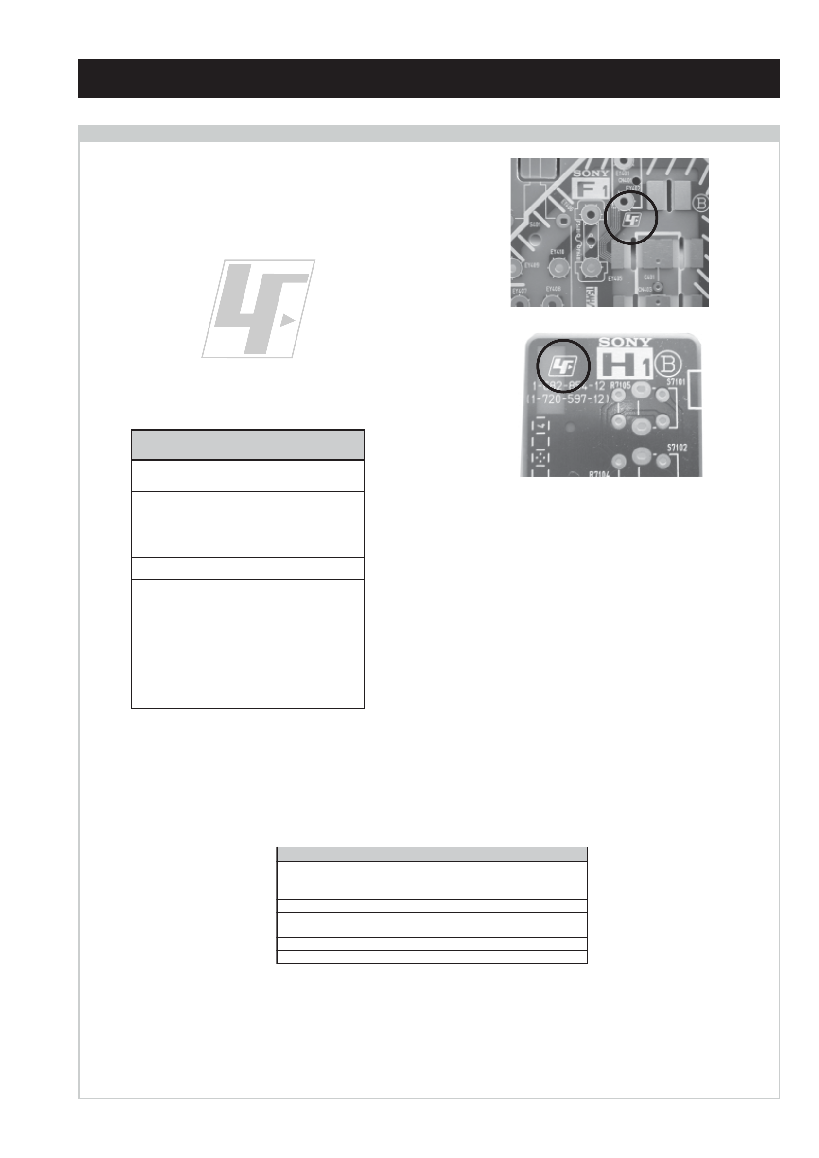
CAUTION
Lead Free Soldered Boards
The circuit boards listed below [Table 1] used in these models
may have been processed using Lead Free Solder. The boards are
identified by the LF logo located close to the board designation
e.g. F1, H1 etc [ see examples ]. The servicing of these boards
requires special precautions to be taken as outlined below.
example 1
example 2
Table 1
draoB noitcnuF
A
BecafretnI_A,SDVL,etarnacS,dnekcaB
CtuOB,G,R
DnoitcelfeD
2DnoitcelfeDedoMtramS
1F
GylppuSrewoP
1H
JstekcoSdnagnihctiwSO/ItracSVA
,srotalugeR,renuT,noitcelfeD,oiduA
ecafretnIB,J
ybdnatS/SCRIS/esuF/hctiwSrewoP
DEL
dnaenohpdaeH/tupnIVAtnorF
sehctiwSlortnoC
MVnoitaludoMyticoleV
It is strongly recommended to use Lead Free Solder material in order to guarantee optimal quality of new solder joints. Lead Free Solder is
available under the following part numbers :
rebmuntraP retemaiD skrameR
91-500-046-7mm3.0gK52.0
02-500-046-7mm4.0gK05.0
12-500-046-7mm5.0gK05.0
22-500-046-7mm6.0gK52.0
32-500-046-7mm8.0gK00.1
42-500-046-7mm0.1gK00.1
52-500-046-7mm2.1gK00.1
62-500-046-7mm6.1gK00.1
Due to the higher melting point of Lead Free Solder the soldering iron tip temperature needs to be set to 370 degrees centigrade. This
requires soldering equipment capable of accurate temperature control coupled with a good heat recovery characteristics.
For more information on the use of Lead Free Solder, please refer to http://www.sony-training.com
- 3 -
LEDOMMETI metsySnoisiveleT metsySoeretS egarevoClennahC metsySroloC
BL,I,K/D,H/G/B
EK/D,H/G/B
KK/D,H/G/B
UI oeretSMACIN96B-12B:FHUI
MACIN/NAMREG
oeretS
MACIN/NAMREG
oeretS
MACIN/NAMREG
oeretS
Q-B,01F-20F,30S-10S,21R-1R,21E-2E:FHV
96R-12R,96B-12B,96F-12F,96E-12E:FHU
02S-10S:VTELBAC
14S-12S:REPYH
,30S-10S,21R-1R,21E-2E:FHV
96R-12R,96E-12E:FHU
02S-10S:VTELBAC
14S-12S:REPYH
30S-10S,21R-1R,21E-2E:FHV
96R-12R,96E-12E:FHU
02S-10S:VTELBAC
14S-12S:REPYH
MACES,LAP
85.3CSTN,34.4CSTN
)NIOEDIV(
MACES,LAP
85.3CSTN,34.4CSTN
)NIOEDIV(
MACES,LAP
85.3CSTN,34.4CSTN
)NIOEDIV(
MACES,LAP
85.3CSTN,34.4CSTN
)NIOEDIV(
:EDIWnortinirTDFyalpsiDtalF
)sehcni82(mc17xorppA
ebuTerutciP
)sehcni23(mc28xorppA
]RAER[slanimreTtuptuO/tupnI snoitacificepSlareneG
rotcennocoruEnip-12:1
)dradnatsCELENEC(
.slangis
rotcennocoruEnip-12:2
rotcennocoruEnip-12:3
.BGRrofstupnI
oiduAdnaoediVVTfostuptuO
.BGRrofstupnI
)tuOrotinoM(
.oediVSrofstupnI
ecafretnIkniltramS,)elbatceles(
)68QF82-VK(
)68QF23-VK(
.slangisoediVdnaoiduArofstupnI
.slangisoediVdnaoiduArofstupnI
.slangisoiduAdnaoediVVTfostuptuO
thgieW
.slangisoediVdnaoiduArofstupnI
.slangisoiduAdnaoediVVTfostuptuO
tuptuodnuoS
rekaepstfeLdnathgiR
refooWbuS
stnemeriuqeRrewoPV042-022
noitpmusnoCrewoPW5.0/W031
snoisnemiD
)68QF82-VK(gk54xorppA
)68QF23-VK(gk46xorppA
seirosseccAdeilppuS
)1(rednammoCetomeR549-MR
)2(yrettab6RdetangisedCEI
)SMR(W01x2)rewoPcisuM(W02x2
)SMR(W51x1)rewoPcisuM(W03x1
)68QF82-VK(mm015x335x987xorppA
)68QF23-VK(mm685x685x019xorppA
skcaJonohP
kcajenohpdaeHkcajinimoerets
stupnioiduAskcajonohp
stupnioediVskcajonohp
tupnioediVSNIDnip4
oiduArofelbairavsrotcennoCtuptuO
slangiS
]TNORF[slanimreTtuptuO/tupnI lortnoCderarfnI:metsySlortnoCetomeR
,weiVTxeN,sulPlatigiD,erutcipzH001
serutaeFrehtO
ICA,PAP,lautriV
cdV3
stnemeriuqerrewoP
)AAezis(6R
.ecitontuohtiwegnahcottcejbuserasnoitacificepsdnangiseD
noitangisedCEIseirettab2
ybloD,latigiDEBB,kniltramS,txeteleT
- 4 -
emaNledoM
metI
bmoClaPFFOFFOFFOFFOFFOFFO
PAPNONONONONONO
ytiroirPBGRNONONONONONO
xoBrefooWNONONONONONO
1tracSNONONONONONO
2tracSNONONONONONO
3tracSNONONONONONO
)4(nitnorFNONONONONONO
rotcejorPFFOFFOFFOFFOFFOFFO
B68QF82-VK E68QF82-VK B68QF23-VK E68QF23-VK K68QF23-VK U68QF23-VK
G/BmroNNONONONONOFFO
ImroNNOFFONOFFOFFONO
K/DmroNNONONONONOFFO
SUAmroNFFOFFOFFOFFOFFOFFO
LmroNNOFFONOFFOFFOFFO
TASmroNFFOFFOFFOFFOFFOFFO
MmroNFFOFFOFFOFFOFFOFFO
txeteleTNONONONONONO
oeretSmaciNNONONONONONO
WARNING (UK Models only)
The flexible mains lead is supplied connected to a B.S. 1363 fused
plug having a fuse of 5 AMP rating. Should the fuse need to be
replaced, use a 5AMP FUSE approved by ASTA to BS 1362, ie one
ASA
that carries the
IF THE PLUG SUPPLIED WITH THIS APPLIANCE IS NOT SUITABLE FOR THE OUTLET SOCKETS IN YOUR HOME, IT SHOULD
BE CUT OFF AND AN APPROPRIATE PLUG FITTED. THE PLUG
SEVERED FROM THE MAINS LEAD MUST BE DESTROYED AS A
PLUG WITH BARED WIRES IS DANGEROUS IF ENGAGED IN A
LIVE SOCKET.
When an alternative type of plug is used, it should be fitted with a
5 AMP FUSE, otherwise the circuit should be protected by a 5AMP
FUSE at the distribution board.
T
mark.
How to replace the fuse.
Open the fuse compartment with
a screwdriver blade and replace
the fuse.
FUSE
- 5 -
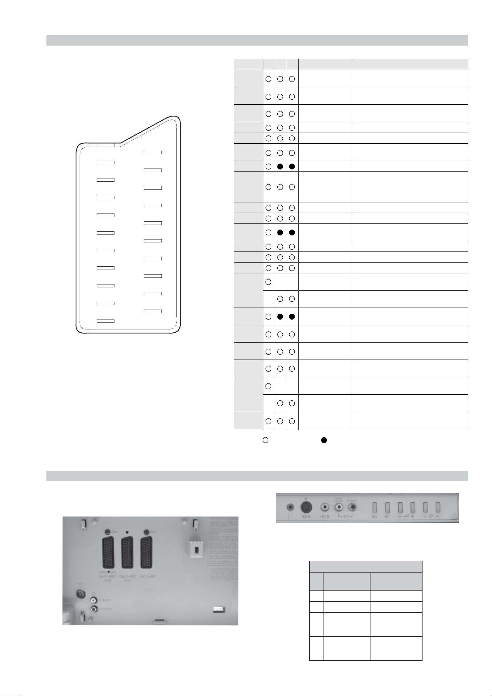
21 pin connector
21
19
17
15
13
11
9
7
5
3
1
20
18
16
14
12
10
8
6
4
2
Pin No 1 2 4 Signal Signal level
1 Audio output B
2
3
4 Ground (audio)
5 Ground (blue)
6 Audio input A
7 Blue input 0.7 +/- 3dB, 75 ohms positive
8 Function select
9 Ground (green)
10 Open
11 Green Green signal : 0.7 +/- 3dB, 75 ohms,
12 Open
13 Ground (red)
14 Ground (blanking)
15
16 Blanking input
_ (S signal Chroma
3
Standard level : 0.5V rms
(right)
Audio input B
(right)
Audio output A
(left)
(left)
(AV control)
_ _ Red input 0.7 +/- 3dB, 75 ohms, positive
input)
(Ys signal)
Output impedence : Less than 1kohm*
Standard level : 0.5V rms
Output impedence : More than 10kohm*
Standard level : 0.5V rms
Output impedence : Less than 1kohm*
Standard level : 0.5V rms
Output impedence : More than 10kohm*
High state (9.5-12V) : Part mode
Low state (0-2V) : TV mode
Input impedence : More than 10K ohms
Input capacitance : Less than 2nF
positive
0.3 +/- 3dB, 75 ohms, positive
High state (1-3V) Low state (0-0.4V)
Input impedence : 75 ohms
17 Ground (video
output)
18 Ground (video
input)
19 Video output 1V +/- 3dB, 75ohms, positive sync 0.3V
(-3+10dB)
_ _ Video input 1V +/- 3dB, 75ohms, positive sync 0.3V
(-3+10dB)
20
21 Common ground
_ Video input
Y (S signal)
(plug, shield)
Connected Not Connected (open) * at 20Hz - 20kHz
1V +/- 3dB, 75ohms, positive sync 0.3V
(-3+10dB)
Rear Connection Panel Front Connection Panel
- 6 -
S-Video
socket
niP
oN
1dnuorG2dnuorG3tupni)langisS(Y,mho57Bd3-/+V1
4tupni)langisS(CBd3-/+V3.0
noitarugifnocniptekcosoediVS
langiS leveLlangiS
V3.0.cnySevitisop
Bd01+3-
evitisop,mho57
.cnyS
AE-6BA SELF DIAGNOSTIC SOFTWARE
The identification of errors within the AE-6BA chassis is triggered in one of two ways :- 1: Busy or 2: Device failure to respo nd to IIC. In the
event of one of these situations arising the software will first try to release the bus if busy (Failure to do so will report with a continuous
flashing LED) and then communicate with each device in turn to establish if a device is faulty . If a device is found to be faulty the relevant
device number will be displayed through the LED (Series of flashes which must be counted) See table 1, non fatal errors are reported using this
method. Each time the software detects an error it is stored within the NVM. See Table 2.
Table 1
How to enter into Table 2
egasseMrorrE
rorreoN00
devreseR10
)noitcetorPtnerruCrevO(PCO20
noitcetorPegatloVrevO30
cnySlacitreVoN40
norewoptarorrERKI50
norewoptaegdelwonkcasubCIIonMVN70
noitcetorPlatnoziroH80
norewoptaegdelwonkcaonrenuT90
rorrErossecorPdnuoS01
devreseR11
rorrEetarnacS21
rorrECAD31
rorrEdnekcaB41
rorrEecnegrevnoCcimanyD51
rorrEPIP61
Flash Timing Example : e.g. error number 3
StBy LED
ON ON ON
OFF
OFF
norewoptawolsenilatadro/dnakcolcsubCII60
DEL
edoC
1. Turn on the main power switch of the TV set.
2. Program Remote Commander for Operation in Service
Mode. [See Page 22].
3. Press ‘AUX/VIDEO’ ‘AUX/VIDEO’ > ‘MENU’ on the
RemoteCommander.
4. Using the Remote Commander, Scroll to the ‘Error’ item
using the down arrow key , then press the right arrow
key .
5. The following table will be displayed indicating the error
count.
Table 2
rotinomrorrE
)setuniM:sruoH(:EMITGNIKROW
:sretnuocrorrE
PCO:20E0
PVO:30E0
CNYSVON:40E0
RKI:50E0
CII:60E0
MVN:70E0
TORPH:80E0
RENUT:90E0
DNUOS:01E0
STLOV9:11E0
ETARNACS:21E0
BMOCD3:31E0
DNEKCAB:41E0
NOCNYD:51E0
EGATLOVHGIH:61E0
HCTIWSVA:71E0
CEDAMORHC:81E0
ACRF:91E0
GNEJP:02E0
CAD:12E0
TORPREKAEPS:42E0
KCITSYROMEM:52E0
33:28
:tceleS:uneMsuoiverP
Note: To clear the error count data press ‘80’ on the Remote
commander.
- 7 -
The operating instructions mentioned here are partial abstracts from the ‘Operating
Instruction Manual’. The page numbers of the ‘Operating Instruction Manual’ remain
as in the manual.
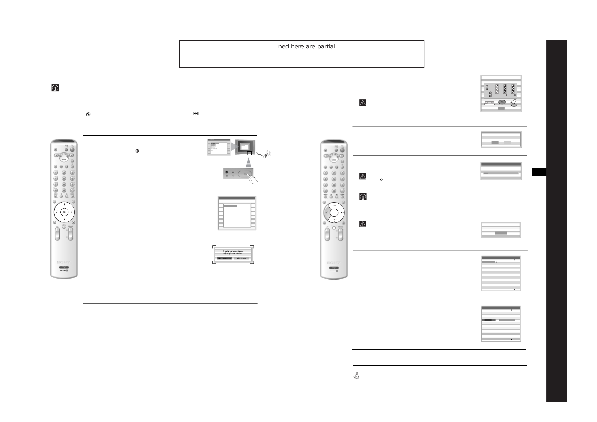
Switching On the TV and Automatically Tuning
The first time you switch on your TV, a sequen ce of menu screens appear on the TV en abl ing you to: 1) choose
the language of the menu screen 2) adjust the picture slant, 3) check how to connect optional equipment to your
TV, 4) search and store all available channels (TV Broadcast) and 5) change the order in which the channels
(TV Broadcast) appear on the screen.
However, if you need to change any of these settings at a later date, you can do so by selecting the appropriate
option in the
(Set Up menu) or by pressing the Auto Start Up Button on the TV set.
4
A diagram will appear showing you how to connect a wide range
of equipment to your TV set. Follow the instructions and finally
press the OK button to remove the diagram and continue the
automatic process.
After the automatic tuning process has finished and any
optional equipment has been connected, we recommend
you follow the instructions explain e d on the section
"Connection Guide" on page 15 to get the optimum settings
Please connect your equipment
according to this chart
:3/q3
:2/ 2
DVD
OK
:1/ 1
related to the optional equipment.
5
1
Connect the TV plug to the mains socket (220-240V AC, 50Hz)
The first time that the TV set is connected, it is usually turned on.
If the TV is off, press the on/off button on the TV set to turn
Language
Select language
English
Deutsch
Español
Français
Italiano
Nederlands
Dansk
Polski
Português
Türkçe
Ελληνικά
Български
Svenska
Pyccкий
Česky
Magyar
Norsk
Suomi
Slovenski
Română
The Auto Tuning menu appears on the screen. Press the OK
button to select Yes.
Language
Select language
English
Ελληνικά
Deutsch
Български
Español
Svenska
Français
Pyccкий
Italiano
Česky
Nederlands
Magyar
Dansk
Norsk
Polski
Suomi
Português
Slovenski
Türkçe
Română
Do you want to start
automatic tuning?
Yes No
on the TV.
The first time you switch on the TV, a Language menu displays
automatically on the TV screen.
6
The TV starts to automatically search and store all
available broadcast channels for you.
This procedure could take some minutes. Please be patient
and do not press any buttons, otherwise autom atic tuning
Auto Tuning
Programmes found: 4
GB
SECTION 1
will not be completed.
2
Press the V, v, B or b buttons on the remote control to select
your language, then press the OK button to confirm your
- 8 -
OK
selection. From now on all the menus will appear in your chosen
language.
Language
Select language
English
Deutsch
Español
Français
Italiano
Nederlands
Dansk
Polski
Português
Türkçe
Ελληνικά
Български
Svenska
Pyccкий
Česky
Magyar
Norsk
Suomi
Slovenski
Română
OK
MENU
In some countries the TV Broadcaster installs the channels
automatically (ACI system). In this case, the TV
Broadcaster sends a menu in which you can select your city
v
by pressing the
or V button and OK to store the
channels.
If no channels were found during the auto tune process, a
message appears automatically on the screen asking you to
connect the aerial. Check the aerial connection (refer to
No channel found.
Please connect aerial
Confirm
GENERAL
page 7). Press the OK button to restart the auto tuning
process.
After all available channels are captured and stored,
a)
If you wish to keep the broadcast channels in the tuned o rde r,
go to step 8.
Programme Sorting
01
TVE
02
TVE2
03
TV3
04
C33
05
C27
06
C58
07
S02
08
S06
RM-945
3
Because of the earth’s magnetism, the picture might slant. The
Picture Rotation menu allows you to correct the picture slant i f
it is necessary.
a)
If it is not necessary, press OK to select Not necessary.
b)
If it is necessary, press B or b to select Adjust now, then press
OK and correct any slant of the picture be tween –5 and +5 by
pressing
v
or V. Finally press OK to store.
If picture slants, please
adjust picture rotation.
Not necessary
Adjust now
RM-945
7
the Programme Sorting menu automatically appears
on the screen enabling you to change the order i n
which the channels are stored.
First Time Operation
8
continued...
b)
If you wish to store the channels in a different order:
1
Press the v or V button to select the programme
number with the channel (TV Broadcast) you wish
to move. Press the
2
Press the v or V button to select the new
b
button.
programme number position for your selected
channel (TV Broadcast). Press the OK button to store.
3
Repeat steps b)1 and b)2 if you wish to change
the order of the other channels.
8
Press the MENU button to remove the menu from the screen
Your TV is now ready for use
Programme Sorting
01
TVE
02
TVE2
03
TV3
04
05
06
07
08
01 TV E
C33
C27
C58
S02
S06
First Time Operation
9
Introducing and Using the Menu System
OK
MENU
MENU
The Picture Adjustment Menu
Your TV uses an On-Screen menu system to guide you through the operations. Use the following buttons on
the Remote Control to operate the menu system:
MENU
The “Picture Adjustment” menu allows you to
alter the picture settings.
To do this:
,
Picture Adjustment
Picture Mode: Live
Contrast:
Reset
Noise Reduction: Auto
Colour Tone: Cool
Press the MENU button and then press OK to
enter this menu. Next press
desired option and press OK. Finally read the
instructions below on how to operate each
option.
OK
Select:Back:
Enter:
you are watching. After selecting this option press OK. Next press
v
or V to select the
v
or V
1
To switch on the menu screens:
Press the MENU button to switch the first level menu on.
Picture Adjustment
Picture Mode: Live
Contrast:
Reset
Noise Reduction: Auto
Colour Tone: Cool
Select: Enter:OKExit:
Picture Adjustment
Picture Mode: Live
Contrast:
Reset
Noise Reduction: Auto
Colour Tone: Cool
Picture Adjustment
Picture Mode: Live
Contrast:
Reset
Noise Reduction: Auto
Colour Tone: Cool
MENU
Select: Enter:OKExit:
MENU
Select: Enter:
OK
MENU
Exit:
Picture Mode This option allows you to customise the Pi cture Mode based on the programme
repeatedly to select:
Personal (for individual settings).
Live (for live broadcast programmes, DVD and Digital Set Top Box receivers)
2
To navigate through the menus:
v
• To highlight and select the desired menu or option, press
• To enter the selected menu or option, press OK or
• To return to the last menu or option, press OK or
• To alter the settings of your selected option, press
- 9 -
• To confirm and store your selection, press OK.
b
B
v/V/B
or V.
.
"Brightness", "Colour" and "Sharpness" level of "Live" and "Movie" mode are fixed in the
factory to get the best picture quality.
.
or b.
Contrast Press
Brightness Press
Movie (for films).
Once you have selected your desired option, press OK to store.
B
or b to reduce or enhance picture contrast. Next press OK to store.
B
or b to darken or brighten the picture. Next press OK to store.
GB
3
To switch off the menu screens:
Press the MENU button to remove the menu from the screen.
RM-945
This option only appears for alter ati on if "Picture Mode" is set to "Personal".
OK
Colour Press
B
or b to decrease or to increase color intensity. Next press OK to store.
This option only appears for alter ati on if "Picture Mode" is set to "Personal".
MENU
Hue Press
B
or b to decrease or to increase the green tones. Next press OK to store.
This option only appears for NTSC signal (e.g. USA video tapes).
Sharpness Press
B
or b to soften or to sharpen the picture. Next press OK to store.
This option only appears for alter ati on if "Picture Mode" is set to "Personal".
Reset Press OK to reset the picture to the factory preset levels.
Noise This option is set to Auto to automatically red uc e the sno w y pic ture that may be
Reduction visible in the broadcast signal. However, it can be modified by pressing
v
or V
to select Off, Low, Mid or High. Finally press OK to store.
Colour Tone This option allows you to alter the tint of the picture. After selecting this option
b
. Next press v or V repeatedly to select: Warm (gives the white colours
press
a red tint), Normal (gives the white colours a neutral tint), Cold (gives the white
colours a blue tint). Next press OK to store.
10
TV Functions
TV Functions
11
The Sound Adjustment Menu
PAP (PICTURE AND PICTUR E)
Picture Adjustment
Picture Mode: Live
Contrast:
Reset
Noise Reduction: Auto
Colour Tone: Cool
Select: Enter:
m
Sound Adjustment
Sound Effect: Dolby Virtual
Treble:
Bass:
Balance:
Reset
Dual Sound: Stereo
Auto Volume: Off
TV Speakers: On
Headphones Set Up
Select: Enter:
MENU
The “Sound Adjustment” menu allows you to
alter the sound settings.
To do this:
Press the MENU button and press
v
, then press OK to enter this menu. Next press
v
or V to select the desired option and press
OK
MENU
Exit:
OK. Finally read the instructions below on how
to operate each option.
Sound Adjustment
Sound Effect: Dolby Virtual
Treble:
Bass:
Balance:
,
OK
MENU
Exit:
Reset
Dual Sound: Stereo
Auto Volume: Off
TV Speakers: On
Headphones Set Up
Select:Back:
Enter:
OK
Sound This option allows you to customise the Sound Effect. After selecting this
v
Effect option press OK. Next press
or V repeatedly to select:
Off (Flat response).
to select
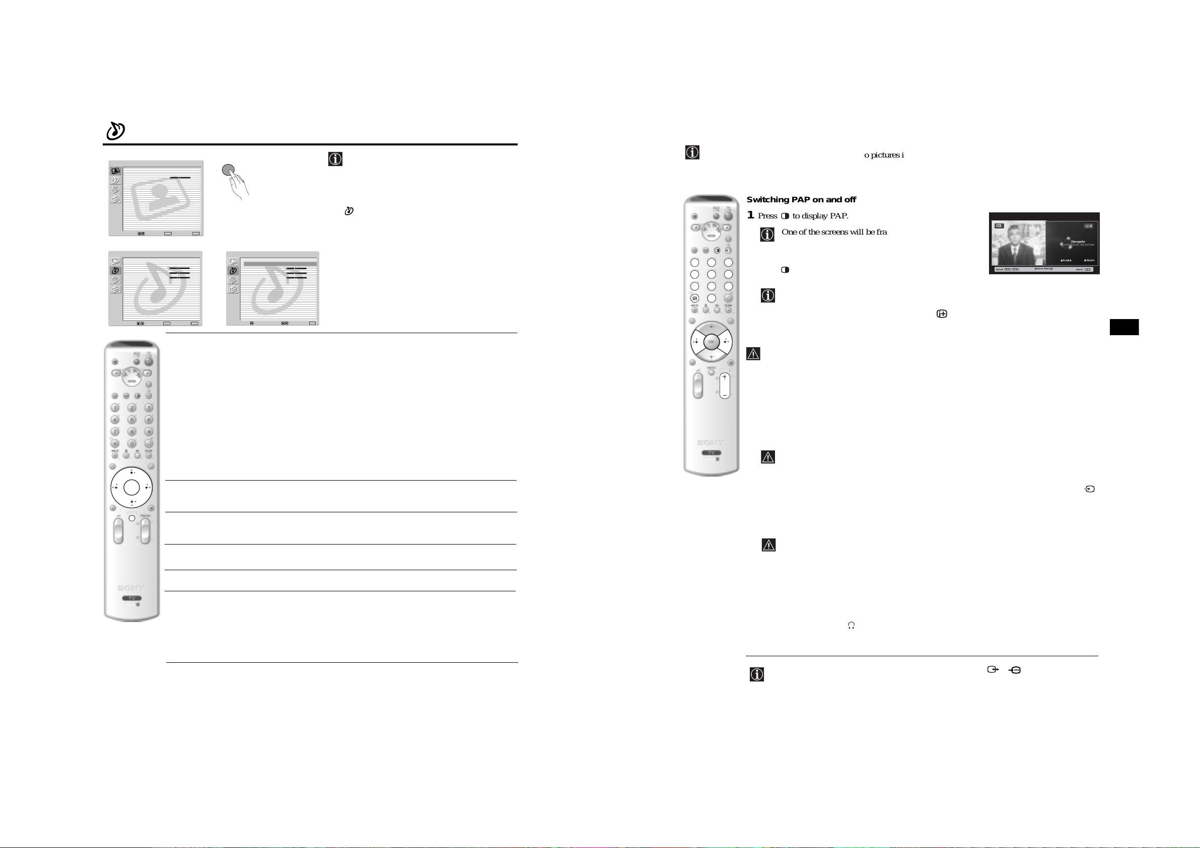
PAP divides the screen into two to watch two pictures in format 4:3 simultaneously.
Switching PAP on and off
1
Press to display PAP.
One of the screens will be framed to indicate that this is
the active screen. It means that when you want to select
123
4
7
6
5
9
8
0
2
the PAP source, you will be doing it in the active screen.
Press again to remove PAP.
On the screen a banner appears guiding you on how to operate
PAP. This banner will disappear after some seconds but it can
always be displayed again by pressing the button.
Changing the active screen
This is only possible if the Media Selector is set to TV.
PROG
To change the active screen (framed), press the
B
or b buttons.
03
Navegador
Configuración del Sistema
Aceptar Versión
PROG+ PROG
Select: Select:
MoveFrame
GB
Natural (Enhances clarity, detail and presence of sound by using “BBE High
Definition Sound system”*).
Dynamic (“BBE Hi gh Definition Sound system”* in t ensifies clarity and
- 10 -
presence of sound for better intelligibility and musical realism).
Dolby** (Dolby Virtual, simulates the sound effect of “Dolby Surround Pro
Virtual Logic”).
Once you have selected your desired option, press OK to store.
OK
Treble Press
B
or b to decrease higher-frequency sounds. Next press OK to store.
RM-945
Selecting PAP source
1
Selecting a TV channel:
B
Press the
button to select the left screen as the active screen. Next press the number buttons
or PROG +/- to select a TV channel.
Video input signals can not be displayed on the left screen.
2
Selecting an input source:
b
Press the
button to se le ct the right screen as the active scree n. Next press repeated ly the
button to show the input signal of the connected equipment on right screen of the TV. For more
MENU
Bass Press
B
or b to decrease or to increase the lower-frequency sounds. Next press
details on which input symbol you wish to choose, please see section "Viewing pictures from
equipment connected to the TV" on page 23.
OK to store.
RF signal (TV broadcast channels) can not be displayed on the right screen.
Balance Press
B
or b to emphasise the left or the right speaker. Next press OK to store.
Selecting the sound
Reset Press OK to reset the sound to the factory preset levels. Next press OK to store.
The sound of the active screen (framed) always comes from the TV speakers.
Besides that, you can listen to the active screen as well as the non active screen via headphones.
RM-945
Dual Sound • For a Stereo broadcast:
Press
v
or V to select Stereo or Mono. Next press OK to store.
• For a bilingual broadcast:
Press
v
or V to select Mono (for mono channel if available), A (for channel 1)
To do this:
With the PAP switched on, refer to the section "The Sound Adjustment Menu", select "Headphones
Set Up" and set the option " PAP Sound" according your preference. For details see page 13.
or B (for channel 2). Next press OK to store.
12
TV Functions
continued...
In PAP (picture and picture) mode, the output from the Scart 2/ 2 is fixed to the right
picture.
TV Functions
19
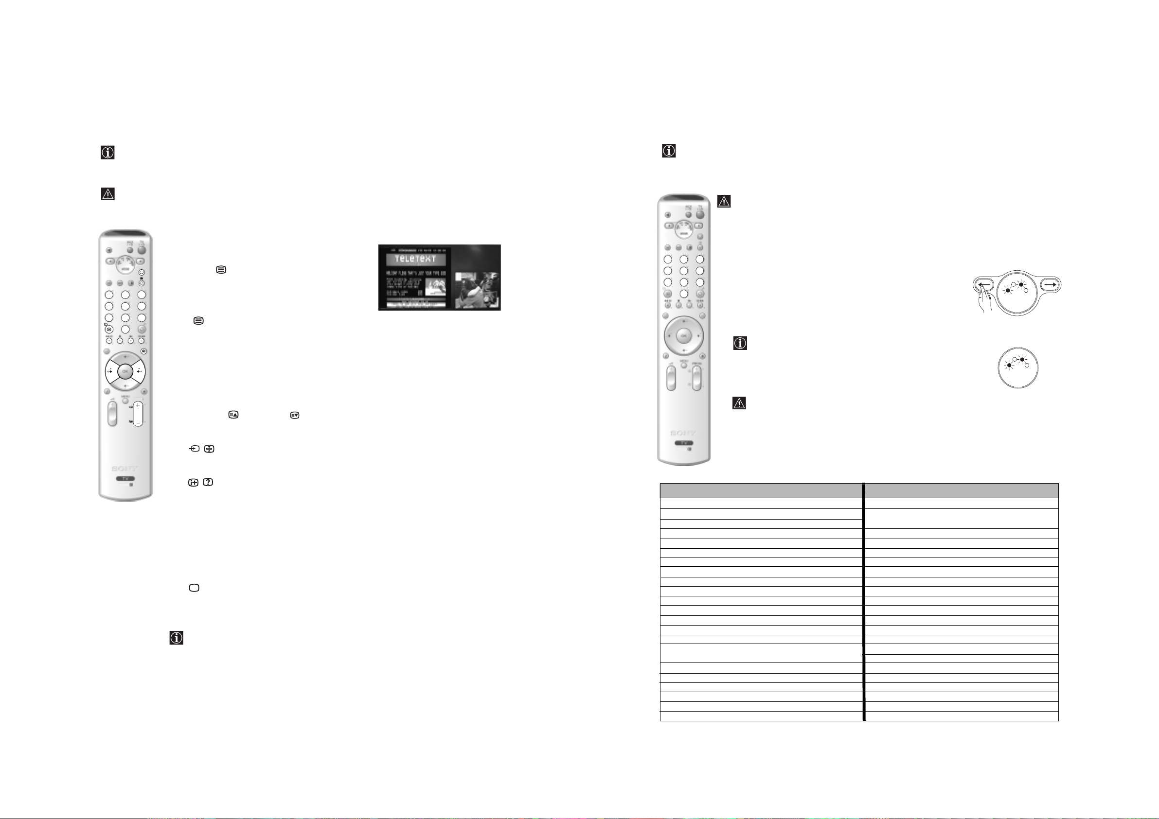
Teletext
Remote Control Configuration for VCR or DVD
Teletext is an information service transmitted by most TV stations. The index page of the teletext service
(usually page 100) gives you information on how to use the service. To operate teletext, use the remote control
buttons as indicated below.
Teletext errors may occur if you use a channel (TV Broadcast) with a weak signal.
In it’s default condition this remote control will operate the basic functions of this Sony TV, Sony DVDs and
most Sony VCRs. To control VCRs and DVDs of other manufacturers (and some Sony VCR models), the
remote control needs to be configured.
fig. 2
To do this:
• Before you start, look up the 3 digit code for your brand of DVD or VCR from the list below.
On those brands that have more than one code, enter the first code number.
• Sony will endeavour to update the software according to market changes. Therefore, please
To switch on Teletext :
1
Select the broadcast channel which carries the teletext
123
4
7
6
5
9
8
0
service you wish to view.
2
Press the button once to enter Picture and Text
(P&T) mode. The screen is divided into two with the
Text display on the left and the TV channel in the
bottom right corner.
3
If you wish to view the Text in full screen mode, press
the button a second time.
123
4
7
6
5
9
8
0
To select a Teletext page:
Input the 3 digit page number, using the numbered buttons.
• If you make a mistake, retype the correct page number.
• If the counter on the screen continues searching, it is because the page
is not available. If this is the case, input another page number.
PROG
- 11 -
To access the next or preceding page:
Press PROG + ( ) or PROG - ( ).
refer to the code table included with the remote control for latest code set.
• A small label is added inside the battery door to allow you to record your brand codes.
1
Press and hold the T button of the remote control for approximately 6
seconds until the green DVD and VCR light of the Media Selector starts
flashing (see fig. 1).
2
While the VCR and DVD lights are flashing, enter all three digits of the
code for your brand of VCR or DVD (see the list below) using the number
buttons on the remote control (see fig. 2).
6 sec.
If your selected code is entered correctly, the VCR or DVD green
light (according to your selection) will be lit momentarily (see fig.3),
otherwise repeat all the above steps.
3
Turn on your VCR or DVD and check that the main functions work.
• If your device is not working or some of the functions do not work please check that you
entered the correct code set or try the next cod e l iste d aga i nst the brand.
fig. 1
R
C
V
MODE
R
C
V
D
V
T
fig. 3
D
V
T
MODE
V
D
A
U
X
V
D
A
U
X
• Not all brands are covered and not all models of every brand may be covered.
To freeze a teletext page:
Press / button. Press again to cancel the freeze.
RM-945
4
Always remember to press the T or t button until the green light iluminates according to
the equipment you want to operate with this remo te con trol: VCR, TV or DVD.
To reveal concealed information (e.g: answer to a quiz):
RM-945
Press / button. Press again to conceal the information.
VCR Brand List DVD Brand List
To select a sub page:
A teletext page may consist of several s ub pages. In this ca s e , one or more arrows appear next to
the page number and an information box is displayed at the bottom of the screen showing the
number of sub pages contai ned on this page. As soon as sub pages are available, they start to
B
automatically appear. If you want to stop the show and select your desired sub page, press
b
repeatedly.
or
To Switch Off Teletext:
Press button.
Fastext
Fastext service lets you access Teletext pag e s with on e button push.
When you are in Teletext mode and Fastext is broadcast, a colour coded menu appears at
the bottom of the teletext page. Press the appropriate coloured button (red, green, yellow
or blue) to access the page corresponding to your menu choice.
Brand Code Brand Code
SONY (VHS) 301, 302, 303, 308, 309,362
SONY (BETA) 303, 307, 310
SONY (DV) 304, 305, 306
AIWA 325, 331, 351
AKAI 326, 329, 330
DAEWOO 342, 343
GRUNDIG 358, 355, 360, 361, 320, 351, 366
HITACHI 327, 333, 334
JVC 314, 315, 322, 344, 352, 353, 354, 348, 349
LG 332, 338
LOEWE 358, 355, 360, 361, 320, 351
MATSUI 356, 357
ORION 328
PANASONIC 321, 323
PHILIPS 311, 312, 313, 316, 317, 318, 358, 359,
363, 364
SAMSUNG 339, 340, 341, 345
SANYO 335, 336
SHARP 324
THOMSON 319, 350, 365
TOSHIBA 337
SONY 001, 029, 030, 036, 037, 038, 039, 040,
041, 042, 043, 044, 053, 054, 055
AIWA 021
AKAI 032
DENON 018, 027, 020, 002
GRUNDIG 009, 028, 023, 024, 016, 003
HITACHI 025, 026, 015, 004, 035
JVC 006, 017
KENWOOD 008
LG 015, 014, 034
LOEWE 009, 028, 023, 024, 016, 003
MATSUI 013, 016
ONKYO 022, 033
PANASONIC 018, 027, 020, 002, 045, 046, 047
PHILIPS 009, 028, 023, 024, 016, 003, 031
PIONEER 004, 050, 051, 052
SAMSUNG 011, 014
SANYO 007
SHARP 019 , 027
THOMSON 012
TOSHIBA 003, 048, 049
YAMAHA 018, 027, 020, 002
20
Teletext
24
Additional Information
Lifting the TV Set
Technical Specifications
206779201
TV system:
I
Colour system:
PAL
SECAM, NTSC 3.58, 4. 43 (only
Video In)
Channel Coverage:
UHF: B21-B69
Picture Tube:
Flat Display FD Trinitron WIDE:
KV-28FQ86U: 28” (approx. 71cm.
measured diagonally)
KV-32FQ86U: 32" (approx. 82cm.
measured diagonally)
- 12 -
Rear Terminals
• AV1
1/ 1
21-pin scart connector
(CENELEC standard)
including audio/video input,
RGB input, TV audio/video
output.
• AV2
2/ 2
21-pin Scart connector
(CENELEC standard)
including audio/video input,
RGB input, monitor audio/video
output.
• AV3
3/3
• audio outputs (Left/Right)
S
21-pin Scart connector
(CENELEC standard)
including audio/video input,
S video input, selectable
audio/video output and
SmartLink interface.
- phono jacks
Sound Output:
2 x 20 W (music power)
2 x 10 W (RMS)
Woofer:
30 W (music power)
15 W (RMS)
Power Consumption:
KV-28FQ86U: 130 W
KV-32FQ86U: 130 W
Standby Power Consumption:
0.5 W
Dimensions (w x h x d) :
KV-28FQ86U:
approx. 789 x 533 x 510 mm.
KV-32FQ86U:
approx. 910 x 586 x 586 mm.
Weight:
KV-28FQ86U: approx. 45 Kg.
KV-32FQ86U: approx. 64 Kg.
Accessories supplied:
• 1 Remote Control (RM-945)
• 2 Batteries (IEC designated,
AA size)
GB
2-067-792-01
Front Terminals
S
• 4 S Video input – 4 pin
DIN.
• 4 video input – phono
jack.
• 4 audio input – phono
jacks.
• headphones jack.
Design and specifications are subject to change without notice.
Other features:
• 100 Hz picture, Digital Plus.
• Teletext, Fastext, TOPtext.
•NexTView.
• SmartLink.
• TV system autodetection.
• Dolby Virtual.
• BBE Digital.
•NICAM.
•PAP.
• ACI (Auto Channel
Installation).
Optional ac cessories:
• Stand especially designed for this
TV
KV-28FQ86U: SU-28FQ3.
KV-32FQ86U: SU-32FQ3.
Additional Information
http://www.sony.net.
Printed in UK
27
Troubleshooting
Here are some simple solutions to problems which may affect the pict u re and sound.
Problem
No picture (screen is dark) and no
sound.
Solution
• Check the aerial connection.
• Plug the TV in and press the button on the front of the TV.
• If the standby indicator is on, press TV button on
the remote control.
Problem
No unscrambled picture whilst
viewing an unscrambled channel with
a decoder or a Set Top Box connected
through the Scart connector
S
3/ 3.
v, V, B
in PAP mode.
and b buttons do not work
Solution
• Using the menu system, select the “Features” menu and set “AV3 Output”
to “TV” (see page 15).
• Check that the Decoder or the Set Top Box is not connected on the
scart 2/ 2.
• PAP navigat ion is only possible in TV mod e, please check that Media
Selector is set to TV.
Poor or no picture (screen is dark), but
good sound.
No picture or no menu information
from equipment connected to the
Scart connector.
Good picture, no sound.
No colour on colour programmes.
When you switch on the TV the last
- 13 -
channel you were watching before
switching the TV off does not appear.
Distorted picture when changing
programmes or selecting teletext.
Wrong characters appear when
viewing NexTView.
Picture slanted.
• Using the menu system, select the “Picture Adjustment” menu and select
“Reset” to return to the factory settings (see page 11).
• Check that the optional equipment is on and press the button
repeatedly on the remote control until the co rrect inp ut symbol is
displayed on the screen (see page 23).
Press the + button on the remote control.
Check that “TV Speakers” is “On” in the “Sound Adjustment”
menu(see page 13).
Check that headphones are not connected.
• Using the menu system, select th e “Pi ct ure Adjustment” menu and sele ct
“Reset” to return to factory settings (see page 11).
• This is not a malfunction. Press the number buttons on the remote control
to select the desired channel.
• Turn off any equipment connected to the Scart connector on the rear of the
TV.
• Use the menu system to enter the “Language” me nu (see page 16) and
select the same language that NexTView is broadcast in.
• Using the menu system, select the “Picture Rotation” option in the
“Features” menu to correct the picture slant (see page 15).
Remote control does not function.
The standby indicator on the TV
flashes.
• If you continue to experience problems, have your TV serviced by qualified personnel.
• Never open the casing yourself.
• Check that the Media Selector on the remote control is set to the device
you are using (VCR, TV or DVD).
• If the remote control does not operate the VCR or DVD even when the
Media Selector has been set correct ly, enter t he ne cessary code set as
explained on page 24.
• Replace the batteries.
GB
• Contact your nearest Sony service centre.
Snowy picture when viewing a TV
channel.
28
Additional Information
• Using the menu system, select the “Manual Programme Preset” menu and
adjust Fine Tuning (AFT) to obtain better picture reception (see page 18).
• Using the menu system, select the “Noise Reduction” option in the
“Picture Adjustment” menu and select “Auto” to reduce the noise in the
picture (see page 11).
continued...
Additional Information
29
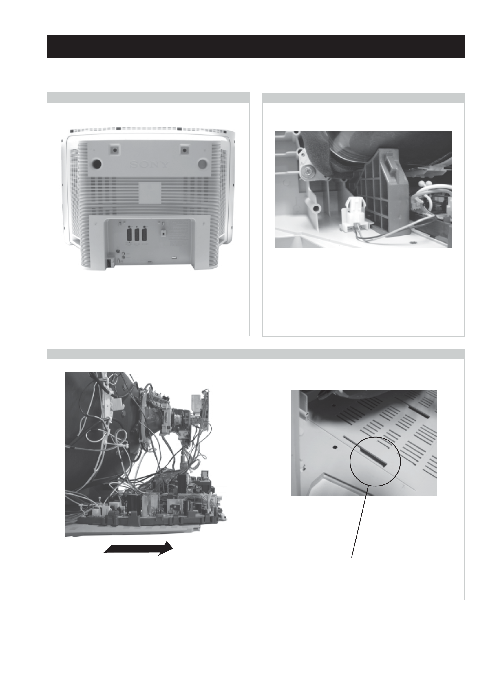
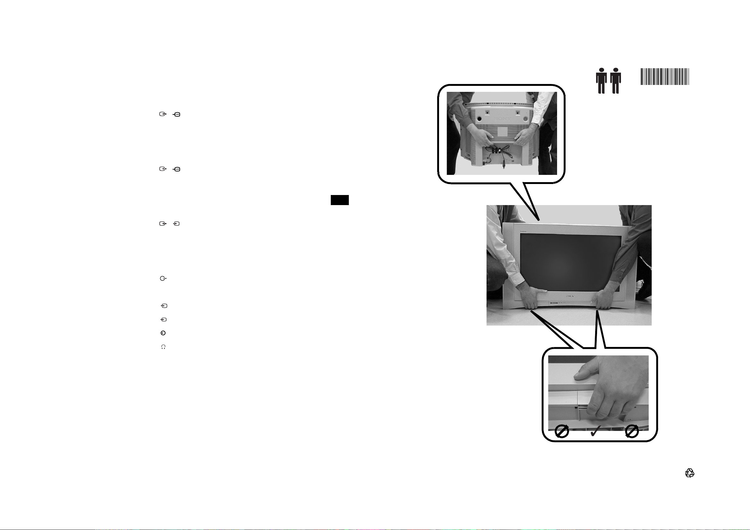
SECTION 2 DISASSEMBLY
2-1. Rear Cover Removal
=>
=>
=>
=>
=>
=>
=>
=>
2-2. Speaker Connector Disconnection
=>
=>
=>
=>
Remove the rear cover fixing screws indicated and pull the
rear cover backwards away from the set. Take care when
removing the rear cover not to damage the speaker cable
[Disconnect the speaker connector] a speaker is fitted inside
the rear cover.
2-3. Chassis Removal and Refitting
Before completely removing the rear cover disconnect the
speaker connector which is located on the inside of the set.
To remove lift the main bracket rear slightly and slide the
chassis away from the beznet. Ensure that the interconnecting
leads are released from their purse locks to prevent damage
being caused.
When refitting the chassis ensure that the main bracket is
located in the beznet guide slots before sliding the chassis
forwards. Refit the inter-connecting leads in their respective
purse locks.
- 14 -
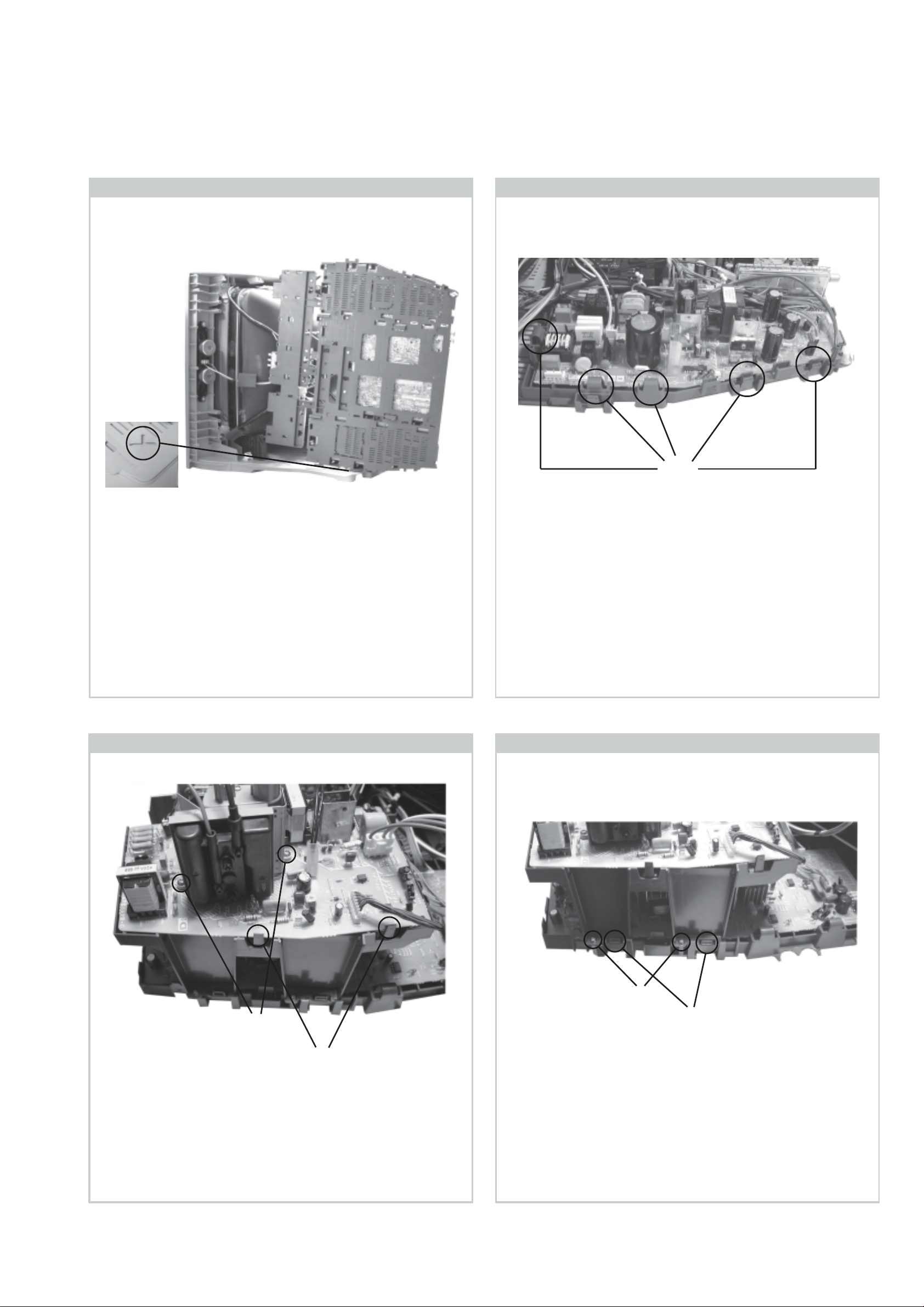
2-4. Service Position 2-5. G Board Removal
Clips
To place the chassis in the service position, insert the main
bracket firmly into the T-slot located on the left corner of the
beznet as indicated (see inset). To gain access to the underside
of the boards follow the instructions on page 17. [Removal
and Replacement of the main bracket bottom plates].
2-6. D2 Board Removal
To remove the G Board remove the two screws from the
middle of the board, release the clips circled and ease the
board gently away from the support bracket.
2-7. D Board Removal
Screws
Clips
To remove the D2 board remove the two screws circled,
release the clips circled and ease the board gently away from
the support bracket.
Screws
Clips
To remove the D board first remove the D2 bracket by
removing the two screws circled and releasing the four
clips (two on each side of the bracket). The D board can
then be removed using the same method as the G board
but with the necessity to remove only one screw from the
middle of the D board.
- 15 -
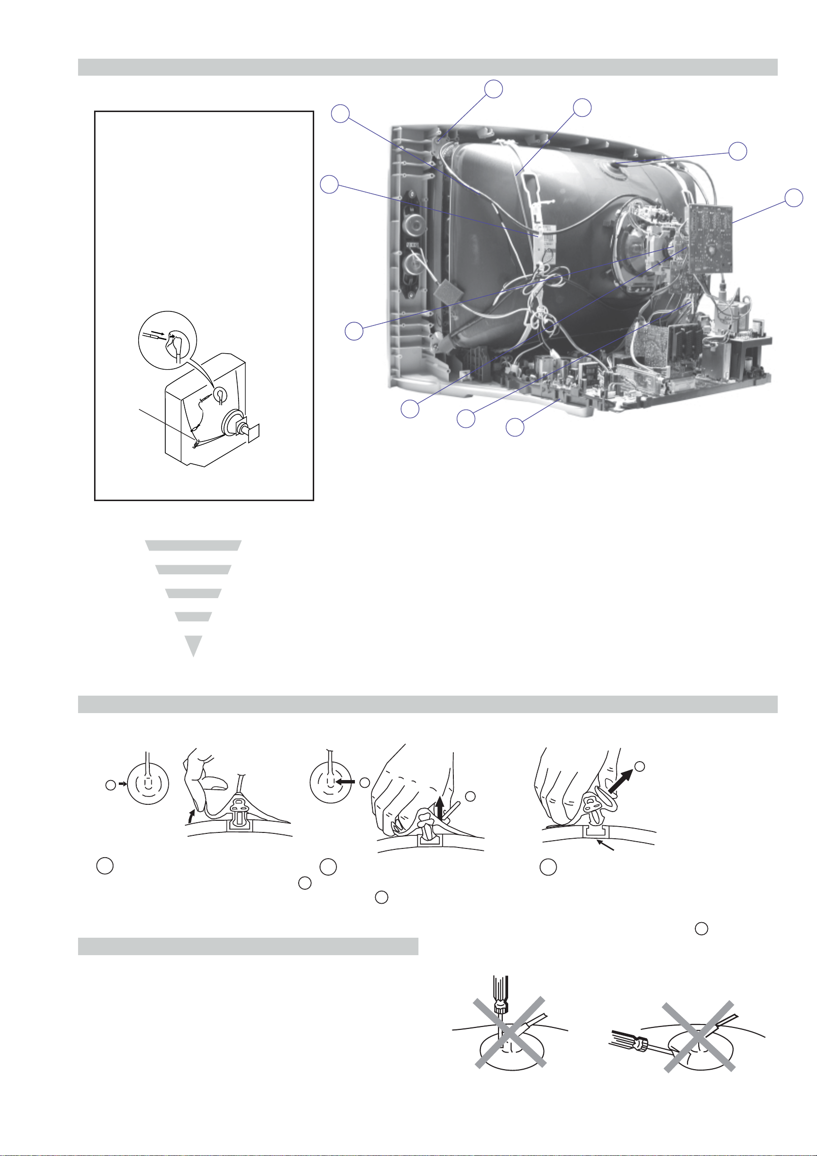
2-8. Picture Tube Removal
10
WARNING:
BEFORE REMOVING
THE ANODE CAP
High voltage remains in the CRT even
after the power is disconnected. To
avoid electric shock, discharge CRT
before attempting to remove the anode
cap. Short between anode and CRT
coated earth ground strap.
8
7
6
9
1
3
Coated Earth
Ground Strap
5
2
4
1. Discharge the anode of the CRT and remove the anode cap.
2. Unplug all interconnecting leads from the Deflection yoke, neck
assy , degaussing coils and CR T grounding strap.
3. Remove the C Board from the CRT.
4. Remove the chassis assembly.
5. Loosen the Neck assembly fixing screw and remove.
6. Loosen the Deflection yoke fixing screw and remove.
7. Place the set with the CRT face down on a cushion and remove
the Degaussing Coil holders.
8. Remove the Degaussing Coils.
9. Remove the CRT grounding strap and spring tensioners.
10. Unscrew the four CRT fixing screws [ located on each CRT
corner ] and remove the CRT.
[Take care not to handle the CRT by the neck.]
Removal of the Anode-Cap
REMOVAL PROCEDURE.
a
1
Turn up one side of the rubber cap in
the direction indicated by the arrow a
2 Using a thumb pull up the rubber cap
firmly in the direction indicated by the
b
arrow b
How to handle the Anode-Cap
1 . To prevent damaging the surface of the anode-cap do not use
sharp materials.
2. Do not apply too great a pressure on the rubber, as this may cause
damage to the anode connector.
3. A metal fitting called a shatter hook terminal is fitted inside the
rubber cap.
4. Do not turn the rubber foot over excessively, this may cause
damage if the shatter hook sticks out.
c
b
Anode button
3 When one side of the rubber cap is
separated from the anode button, the
anode-cap can be removed by turning
up the rubber cap and pulling it up in
the direction of the arrow c
- 16 -
 Loading...