

SONY KV-28FC60 Service Manual
http://cxema.ru
SERVICE MANUAL
AE-5
CHASSIS
MODEL COMMANDER DEST CHASSIS NO.
KV-28FC60 RM-892 Europe SCC-Q11K-A
KV-28FC60/Z RM-892 Europe SCC-Q11J-A
MODEL COMMANDER DEST CHASSIS NO.
KV-32FC60 RM-892 Europe SCC-Q11G-A
KV-32FC60/Z RM-892 Europe SCC-Q11H-A
1
http://cxema.ru
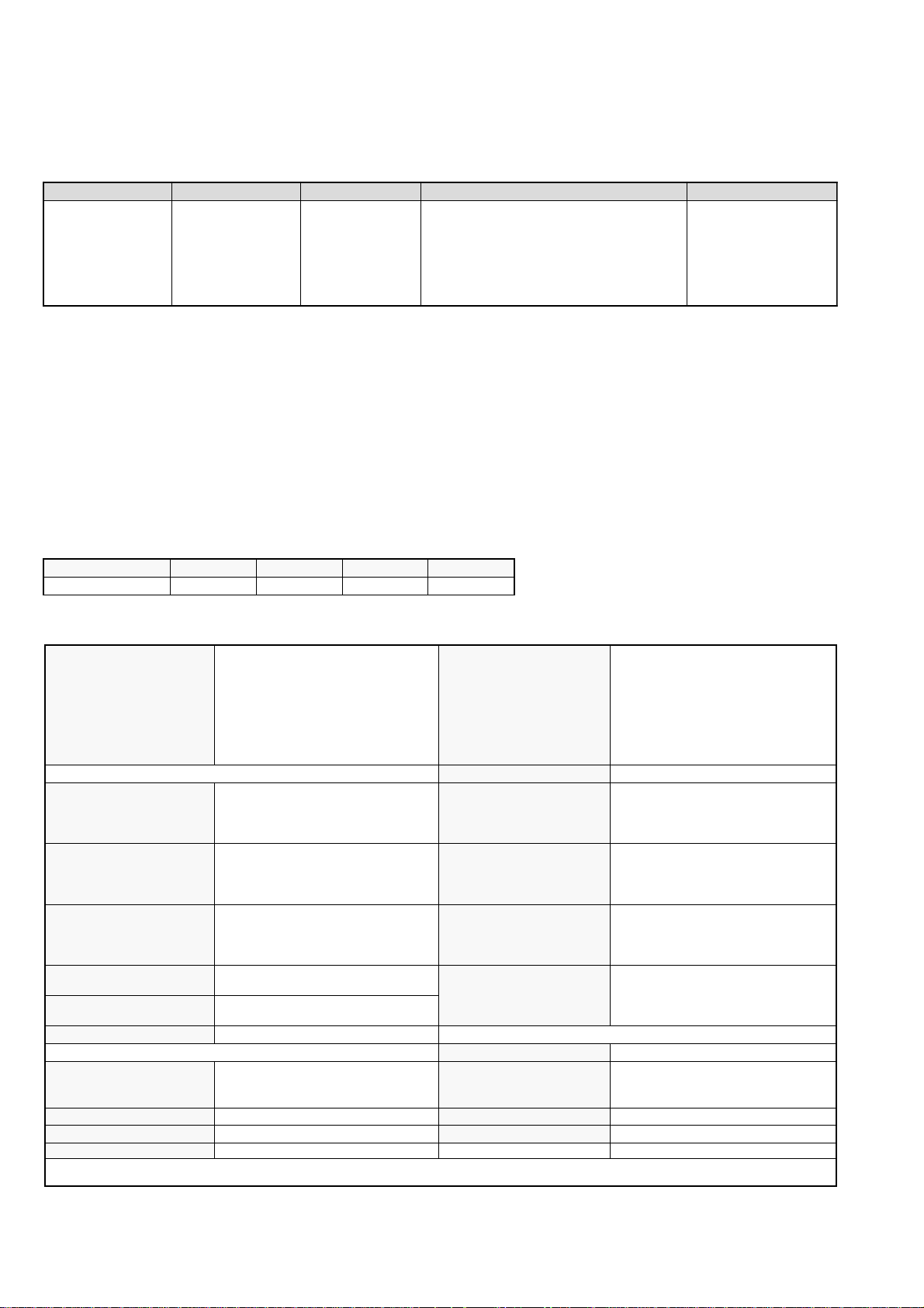
LEDOMMETI metsySnoisiveleT metsySoeretS egarevoClennahC metsySroloC
PEAI,L,K/D,H/G/B
ledoM 06CF82 Z/06CF82 06CF23 Z/06CF23
noitpmusnoCrewoPW231W231W031W031
oeretS
MACIN/NAMREG
06F-12F:FHU01F-20F:FHVL
96E-12E:FHU
14S-1S:)1(VTELBAC
96B-12B:FHUI
21E-2E:FHVH/G/BQ-B:ELBAC
01U-1U,01M-1M,50S-10S:)2(VTELBAC
96-12:FHU)C(2H-A:FHVAILATI
MACES,LAP
85.3CSTN,34.4CSTN
)NIOEDIV(
nortinirTDF
ebuTerutciP
]RAER[slanimreTtuptuO/tupnI
rotcennocoruEnip-12:1
)dradnatsCELENEC(
rotcennocoruEnip-12:2
rotcennocoruEnip-12:3
skcaJACRslangiSoiduAroftuptuO
slanimretrekaepslanretxENIDnip2
tupnioediVSNIDnip4
kcajenohpdaeHkcajinimoerets stnemeriuqerrewoP
)yllanogaid
)yllanogaid
.BGRrofstupnI
.slangis
)elbatceles(
)tuorotinom(
]TNORF[slanimreTtuptuO/tupnI
)sehcni82(mc17xorppA
)sehcni23(mc28xorppA
noitcelfedeerged011
oiduAdnaoediVVTfostuptuO
.oediVSrofstupnI
.oediVSrofstupnI
slangisoediV/oiduAfostuptuO
tuptuodnuoS
derusaemerutcipmc66xorppA(
derusaemerutcipmc67xorppA(
.slangisoediVdnaoiduArofstupnI
.slangisoediVdnaoiduArofstupnI
.slangisoiduAdnaoediVVTfostuptuO
.slangisoediVdnaoiduArofstupnI
refoowbuS
stnemeriuqeRrewoPV042-022
snoisnemiD
thgieW
seirosseccAdeilppuS
serutaeFrehtO
298-MR
metsyslortnocetomeRlortnocderarfnI
snoisnemiD)d/h/w(mm32x55x012xorppA
thgieW)yrettabgnidulcniton(g011xorppA
erutciPzH001
cdV3
)AAezis(6R
rekaepstfeLdnathgiR
)rewoPcisuM(W52x2
)SMR(W51x2
mm)d(335x)h(794x)w(277"82
mm)d(855x)h(465x)w(768"23
gk5.24xorppA"82
gk56xorppA"23
)1(rednammoCetomeR298-MR
)2(yrettab6RdetangisedCEI
,weiVTxeN,oeretsMACIN
retliFbmoClatigiD
resilauqEcihparG
noitangisedCEIseirettab2
.ecitontuohtiwegnahcottcejbuserasnoitacificepsdnangiseD
2
http://cxema.ru
metI
emaNledoM
bmoClaPNONONONO
PIPFFOFFOFFOFFO
ytiroirPBGRNONONONO
xoBrefooWNONONONO
1tracSNONONONO
2tracSNONONONO
)3(niraeRpoTNONONONO
4tracSNONONONO
rotcejorPFFOFFOFFOFFO
edom9:61niBKANONONONO
G/BmroNNONONONO
ImroNNONONONO
K/DmroNNONONONO
SUAmroNFFOFFOFFOFFO
LmroNNONONONO
TASmroNFFOFFOFFOFFO
MmroNFFOFFOFFOFFO
txeteleTNONONONO
oeretSmaciNNONONONO
06CF82-VK Z/06CF82-VK 06CF23-VK Z06CF23-VK
WARNING (UK Models only)
The flexible mains lead is supplied connected to a B.S. 1363 fused
plug having a fuse of 5 AMP rating. Should the fuse need to be
replaced, use a 5 AMP FUSE approved by ASTA to BS 1362, ie one
that carries the
IF THE PLUG SUPPLIED WITH THIS APPLIANCE IS NOT SUITABLE
FOR THE OUTLET SOCKETS IN YOUR HOME, IT SHOULD BE CUT
OFF AND AN APPROPRIATE PLUG FITTED. THE PLUG SEVERED
FROM THE MAINS LEAD MUST BE DESTROYED AS A PLUG WITH
BARED WIRES IS DANGEROUS IF ENGAGED IN A LIVE SOCKET.
When an alternative type of plug is used, it should be fitted with a
5 AMP FUSE, otherwise the circuit should be protected by a 5 AMP
FUSE at the distribution board.
ASA
T
mark.
How to replace the fuse.
Open the fuse compartment with
a screwdriver blade and replace
the fuse.
FUSE
3
http://cxema.ru
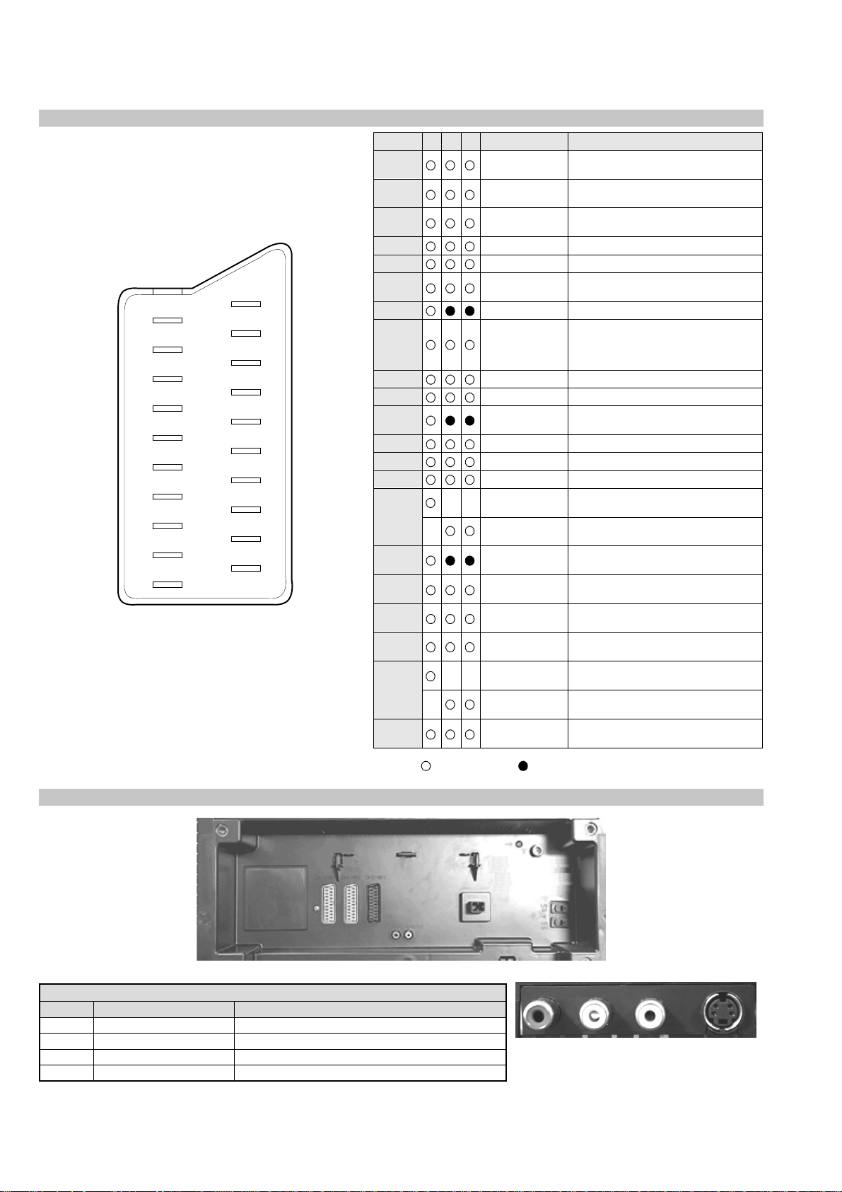
21 pin connector
21
19
17
15
13
11
9
7
5
3
1
20
18
16
14
12
10
8
6
4
2
Pin No 1 2 4 Signal Signal level
1 Audio output B
2
3
4 Ground (audio)
5 Ground (blue)
6 Audio input A
7 Blue input 0.7 +/- 3dB, 75 ohms positive
8 Function select
9 Ground (green)
10 Open
11 Green Green signal : 0.7 +/- 3dB, 75 ohms,
12 Open
13 Ground (red)
14 Ground (blanking)
15
_ (S signal Chroma
16 Blanking input
17 Ground (video
18 Ground (video
19 Video output 1V +/- 3dB, 75ohms, positive sync 0.3V
20
_ Video input
21 Common ground
(right)
Audio output B
(right)
Audio output A
(left)
(left)
(AV control)
_ _ Red input 0.7 +/- 3dB, 75 ohms, positive
input)
(Ys signal)
output)
input)
_ _ Video input 1V +/- 3dB, 75ohms, positive sync 0.3V
Y (S signal)
(plug, shield)
Standard level : 0.5V rms
Output impedence : Less than 1kohm*
Standard level : 0.5V rms
Output impedence : More than 10kohm*
Standard level : 0.5V rms
Output impedence : Less than 1kohm*
Standard level : 0.5V rms
Output impedence : More than 10kohm*
High state (9.5-12V) : Part mode
Low state (0-2V) : TV mode
Input impedence : More than 10K ohms
Input capacitance : Less than 2nF
positive
0.3 +/- 3dB, 75 ohms, positive
High state (1-3V) Low state (0-0.4V)
Input impedence : 75 ohms
(-3+10dB)
(-3+10dB)
1V +/- 3dB, 75ohms, positive sync 0.3V
(-3+10dB)
Connected Not Connected (open) * at 20Hz - 20kHz
Rear Connection Panel
noitarugifnocniptekcosoediVS
oNniP langiS leveLlangiS
1dnuorG2dnuorG3tupni)langisS(Y Bd01+3-V3.0.cnySevitisop,mho57Bd3-/+V1
4tupni)langisS(C.cnySevitisop,mho57Bd3-/+V3.0
4
S-Video
socket
http://cxema.ru
AE-5 SELF DIAGNOSTIC SOFTWARE
The identification of errors within the AE-5 chassis is triggered in one of two ways :- 1: Busy or 2: Device failure to respond to IIC. In the event
of one of these situations arising the software will first try to release the bus if busy (Failure to do so will report with a continuous flashing LED)
and then communicate with each device in turn to establish if a device is faulty. If a device is found to be faulty the relevant device number will
be displayed through the LED (Series of flashes which must be counted) See table 1., non fatal errors are reported using this method.
metIcitsongaiD
noitpircseD
nonruttonseodrewoPthgiltonseoD
)PCO(tnerrucrevOB+semit2
deppotsnoitcelfeDlacitreVsemit4
ybdnatSsemitfooN
sehsalFDEL
.tiucricneposiesuF
egasseMrorrE
rorreoN00
rorresubC2I10
)noitcetorPtnerruCrevO(PCO20
)noitcetorPegatloVrevO(PVO30
noitcetorPlacitreV40
devreseR50
noitcetorPlatnoziroH60
noitcetorPrekaepS70
redoceDtxeteleT.B-M80
MVN,23C42TS.B-M90
redoceDruoloCniaM,0239ADT,B-J01
xoBerutaeF,B-2B/1B11
retrevnoCA/D,B-1B21
dnekcaB.B-E31
rossecorPdnuoS,D0143PSM.B-J41
ediWotuA,7502DXC.B-J51
esuacelbaborP
noitacoL
.nideggulptonsidrocrewoP
)draoBD(.detrohssiCIrewoP4066CI
)draoBD(detrohssi0076CI
smotpmySdetceteD
noemoctonseodrewoP
VTehtotdeilppussirewopoN
ytluafsiylppusrewopCA
)draoBD(.detrohssi)4086/3086Q(TUO.H
)draoBD(.detrohssi)6086Q(TEFytiraeniL
)draoBD(nepo5386RdeilppustonsiV51+
)draoBD(nepo4386RdeilppustonsiV51-
DEL
edoC
noemoctonseodrewoP
detrohssahenilrewopnodaoL
deppotssaheslupnoitcelfedlacitreV
detrohssahenilrewoP
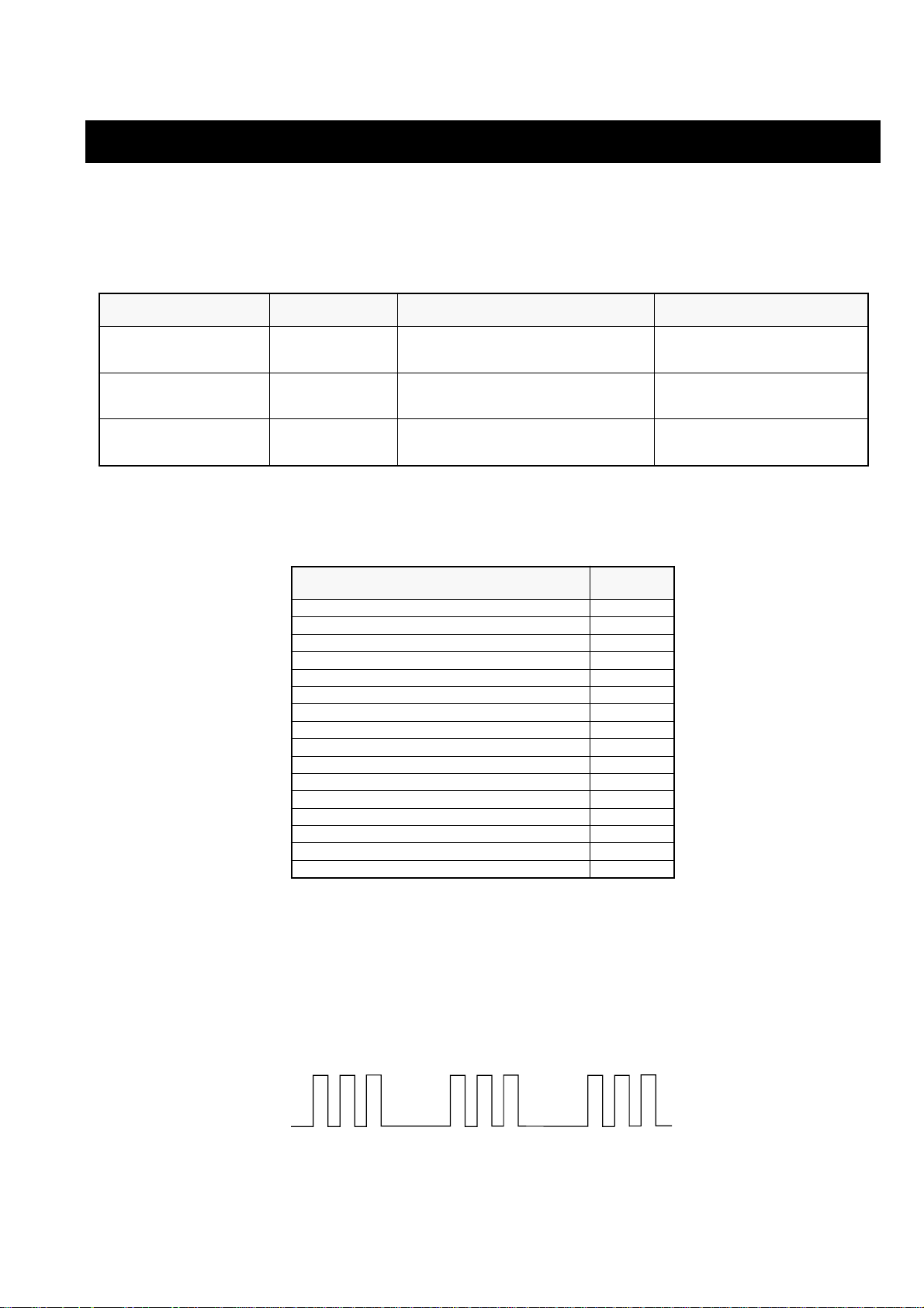
Flash Timing Example : e.g. error number 3
StBy LED
ON ON ON
OFF
5
OFF

http://cxema.ru
Error Detection Monitor
Device acknowledge is used to check IIC errors. Device acknowledge is checked by sending an IIC start sequence during CRT power on. Each
device is checked three times, if there is no acknowledge after each attempt, it will be regarded as an error.
There are three steps to check for errors.
1. IIC line 0
If all devices except the NVM have errors, IIC line 0 error is displayed.
2. Board check
If all devices mounted on one board have errors, board error is displayed.
3. Each device check
If IIC line error and board error are not detected then the device with the error is displayed.
The detected errors can be displayed as follows :
1. Error Monitor Menu.
2. Error Reader.
1. Error Monitor Menu
ERROR MONITOR
Operating Time : 000021 h 55 min
Stored Errors :
1. 100h
2. 401h
3. 704h
4. 000h
5. 000h
A-Board
BP-B CXD2069 MID
J-B TDA9320 Main Col Dec
no error occured
no error occured
Current Error :
Start Error Sequence
6
http://cxema.ru
2. Error Reader Display
The error reader display is connected to the service connector to read actual error codes. The part number for the error reader display is
S-188-900-10. Once an error has been detected it will then be displayed on the two digit error reader. The errors displayed refer to the following
table.
edoCrorrE egasseMrorrE
h000deruccororreoN
h1000CII,rorresuB
h2001CII,rorresuB
h001 draoB-A
h101rednapxEtroP,5781AXC.B-A
h201renuTniaM,6231UT.B-A
h301renuTbuS,0531UT.B-A
h002 draoB-1B
h102 retrevnoCA/D,0829ADS.B-1BxoBerutaeF,456C38P.B-1B
h202 retrevnoCA/D,0829ADS.B-1BxoBerutaeF,456C38P.B-1B
h003 draoB-2B
h103CISEB,7794AAS.B-2B
h004 draoB-PB
h104DIM,9602DXC.B-PB
h005 draoB1D
h105retrevnoCcimanyD,0708AXC,B-1D
h205rednapxEtroP,5781AXC.B-1D
h006 draoB-E
h106dnekcaB,0012DXC.B-E
h007 draoB-J
h107ediWotuA,7502DXC.B-J
h207PIP,8829ADS.B-J
h3073212AXCro0239ADTredoceDruoloCbuS.B-J
h4073212AXCro0239ADTredoceDruoloCniaM.B-J
h507dnuoS-buS,5781AXC.B-J
h607reifilpmA-PH,9037ADT.B-J
h707hctiwSoiduA,TD2246AET.B-J
h807rossecorPdnuoS,D0143PSM.B-J
h907PSDdnuoS,F7339CT.B-J
hA07hctiwSVA,9X12AXC.B-J
h008 draoB-M
h108MVN,23C42TS.B-M
7

http://cxema.ru
TABLE OF CONTENTS
Section Title Page Section Title Page
1. GENERAL
Using the TV menu system .................... 9
Sound Control .................... 9
Using the features menu .................... 10
Sorting TV Channels .................... 12
Teletext .................... 14
Additional Information .................... 15
2. DISASSEMBLY
2-1. Rear Cover Removal .................... 16
2-2. Speaker Disconnection .................... 16
2-3. Chassis Removal .................... 16
2-4. Service Position .................... 17
2-5. S1 Board Removal .................... 17
2-6. J Board Removal .................... 17
2-7. Picture Tube Removal .................... 18
2-8. Removal and replacement of
the Main-Bracket bottom
plates. .................... 19
3. SET-UP ADJUSTMENTS
3-1. Beam Landing .................... 20
3-2. Convergence .................... 21
3-3. Focus .................... 23
3-4. Screen [G2] White Balance .................... 23
5. DIAGRAMS
5-1. Block Diagram (1) .................... 31
Block Diagram (2) .................... 35
Block Diagram (3) .................... 39
Block Diagram (4) .................... 43
5-2. Circuit Board Location .................... 46
5-3. Schematic Diagrams and
Printed Wiring Boards .................... 46
* F2 Board .................... 47
* H2 Board .................... 47
* H4 Board .................... 47
* F1 Board .................... 48
* H3 Board .................... 48
* E Board .................... 49
* M Board .................... 53
* B1 Board .................... 56
* U Board .................... 63
* D Board .................... 65
* A Board .................... 68
* J Board .................... 77
* C Board .................... 83
* D1 Board .................... 87
* VM Board .................... 90
5-4. IC Blocks .................... 90
5-5. Semiconductors .................... 91
4. CIRCUIT ADJUSTMENTS
4-1. Electrical Adjustments .................... 24
4-2. Volume Electrical Adjustments.................... 28
4-3. Test Mode 2 .................... 30
CAUTION
SHORT CIRCUIT THE ANODE OF THE PICTURE TUBE AND THE
ANODE CAP TO THE METAL CHASSIS, CRT SHIELD, OR THE
CARBON PAINTED ON THE CRT, AFTER REMOVAL OF THE
ANODE CAP.
WARNING !!
AN ISOLATION TRANSFORMER SHOULD BE USED DURING ANY
SERVICE WORK TO AVOID POSSIBLE SHOCK HAZARD DUE TO
LIVE CHASSIS, THE CHASSIS OF THIS RECEIVER IS DIRECTLY
CONNECTED TO THE POWER LINE.
SAFETY-RELATED COMPONENT WARNING !!
COMPONENTS IDENTIFIED BY SHADING AND MARKED
SCHEMATIC DIAGRAMS, EXPLODED VIEWS AND IN THE PARTS
LIST ARE CRITICAL FOR SAFE OPERATION. REPLACE THESE
COMPONENTS WITH SONY PARTS WHOSE PART NUMBERS
APPEAR AS SHOWN IN THIS MANUAL OR IN SUPPLEMENTS
PUBLISHED BY SONY.
£ ON THE
6. EXPLODED VIEWS
6-1. Chassis .................... 94
6-2. Picture Tube .................... 96
7. ELECTRICAL PARTS LIST .................... 98
ATTENTION
APRES AVOIR DECONNECTE LE CAP DE’LANODE,
COURT-CIRCUITER L’ANODE DU TUBE CATHODIQUE ET CELUI
DE L’ANODE DU CAP AU CHASSIS METALLIQUE DE L’APPAREIL,
OU AU COUCHE DE CARBONE PEINTE SUR LE TUBE
CATHODIQUE OU AU BLINDAGE DU TUBE CATHODIQUE.
ATTENTION !!
AFIN D’EVITER TOUT RISQUE D’ELECTROCUTION PROVENANT
D’UN CHÁSSIS SOUS TENTION, UN TRANSFORMATEUR
D’ISOLEMENT DOIT ETRE UTILISÈ LORS DE TOUT DÈPANNAGE LE
CHÁSSIS DE CE RÈCEPTEUR EST DIRECTMENT RACCORDÈ Á
L’ALIMENTATION SECTEUR.
ATTENTION AUX COMPOSANTS RELATIFS Á
LES COMPOSANTS IDENTIFIÈS PAR UNE TRAME ET PAR UNE
MARQUE
EXPLOSÈES ET LES LISTES DE PIECES SONT D’UNE IMPOR-
TANCE CRITIQUE POUR LA SÈCURITÈ DU FONCTIONNEMENT, NE
LES REMPLACER QUE PAR DES COMPSANTS SONY DONT LE
NUMÈRO DE PIÈCE EST INDIQUÈ DANS LE PRÈSENT MANUEL OU
DANS DES SUPPLÈMENTS PUBLIÈS PAR SONY.
£ SUR LES SCHÈMAS DE PRINCIPE, LES VUES
LA SECURITÈ!!
8
http://cxema.ru
SECTION 1 GENERAL
13
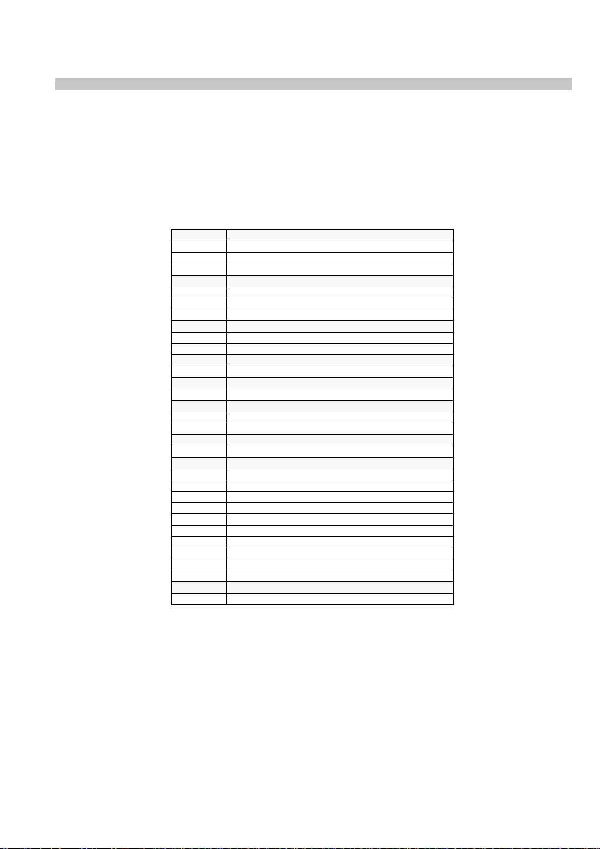
Sound Control
Item Effect/Operation
Equaliser mode Select between the following sound settings
$ Personal
Vocal
Jazz
Rock
Pop
4 Flat (fixed setting, cannot be adjusted)
Equaliser adjustment
You can adjust the mode selected in Equaliser
mode by cutting and boosting of 5 selected
frequency bands.
Only the changes made in Personal can be stored,
the others return to factory setting.
•
Select the desired bar using ” or “, adjust using 4
and $.
Press OK to store.
Balance ” More right
“ More left
Loudness $ Off: Normal
4 On: For music broadcasts
Space $ Off: Normal
4 On: Special accoustic effect
Auto Volume Control 4 On: volume level of the channels will stay the same
independent of the broadcast signal
(e.g. in case of advertisements)
$ Off: volume level changes according to the
broadcast signal
Dual Sound For a bilingual broadcast:
$ A for channel 1
4 B for channel 2
For a stereo broadcast:
$ Mono
4 Stereo
In case of a NICAM stereo broadcast the indication
NICAM appears briefly on the screen.
Headphones
2 Volume Less “ ” More
2 Dual Sound For a bilingual broadcast:
$ A for channel 1
4 B for channel 2
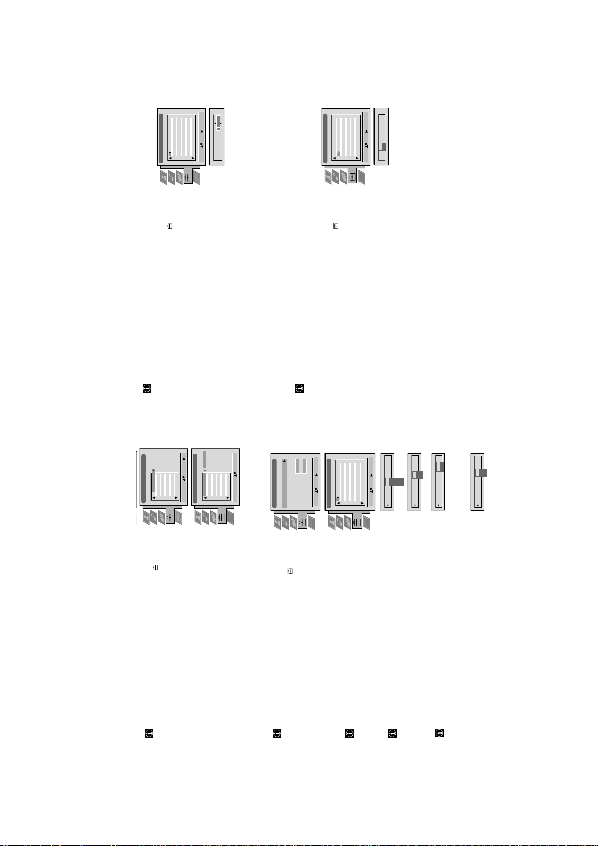
Operation (TV menu system):
Equaliser Adjustment
Sel: Adjust: Confirm:OK
Personal
+
0
–
120 150 1,5K 5 K 10 K
Audio Adjustment
Equaliser Mode Equaliser
Adjustment
Balance
Loudness
Space
Auto Vol. Control
Dual Sound
Volume
Dual Sound
Personal
Mono
Off
On
Mono
Personal
Vocal
Jazz
Rock
Pop
Flat
Select Mode: Confirm: OK
Off
Loudness
Off
On
Balance
Space
Off
On
Volume
Dual Sound
A
B
Dual Sound
Mono
Stereo
Auto Vol. Control
Off
On
The operating instructions mentioned here are partial abstracts from the ‘Operating
Instruction Manual’. The page numbers of the ‘Operating Instruction Manual’ remain
as in the manual.
Operation
Personal
Picture Adjustment
Picture Mode
Contrast
Picture and sound are adjusted at the factory. You can however, adjust
Using the TV menu system
The TV consists of a menu system which is based on a series of user friendly on-screen displays and menus. These displays will help
you get the most from your TV, helping you to change picture and sound settings, to alter the size of the TV picture and to rearrange
the TV channels etc.
Adjusting the picture and sound
Brightness
Colour
them individually.
Sharpness
ResetAINoise Reduction
1 Press MENU.
On
On
Normal
Digital Mode
Select Mode: Enter:
for Picture or for Sound using 4 or $.
Push to ” to enter.
Select the symbol
The menu Picture or Sound Control is displayed.
2 Select the desired item using 4 or $. Push to ” to enter.
3 Adjust the selected item using 4, $, ” and “. Press OK to store.
Live
Refer to the tables on this and the following page for more information.
4 Repeat steps 2 and 3 to adjust other items.
5 Press MENU to return to the normal TV screen.
Picture Control
Item Effect/Operation
Picture Mode $ Live (for live broadcasts)
Movie
Personal
Picture Mode
Contrast
Personal (for individual settings)
4 Movie (for movie broadcasts)
Contrast Less “” More
Brightness* Darker “” Brighter
Colour* Less “” More
Hue** Reddish “” Greenish
Sharpness* Softer “” Sharper
Off
Off
On
On
Normal
Digital+
Advanced
AI
Noise Reduction
Digital Mode
according to the TV signal
Digital+: 100 Hz plus line flicker reduction
broadcasting signal
$ On: Reduces picture noise in case of a weak
(Artificial Intelligence) $ On: Automatic optimization of contrast level
Noise Reduction 4 Off: Normal
Reset Resets picture to the factory preset levels
AI 4 Off: normal
Digital Mode $ Normal: 100 Hz.
4 Advanced: Digital+ plus smoothing of motions
* Only if Personal is selected in Picture Mode
** Only available for NTSC colour signal (e.g. US video tapes)
12
9
http://cxema.ru
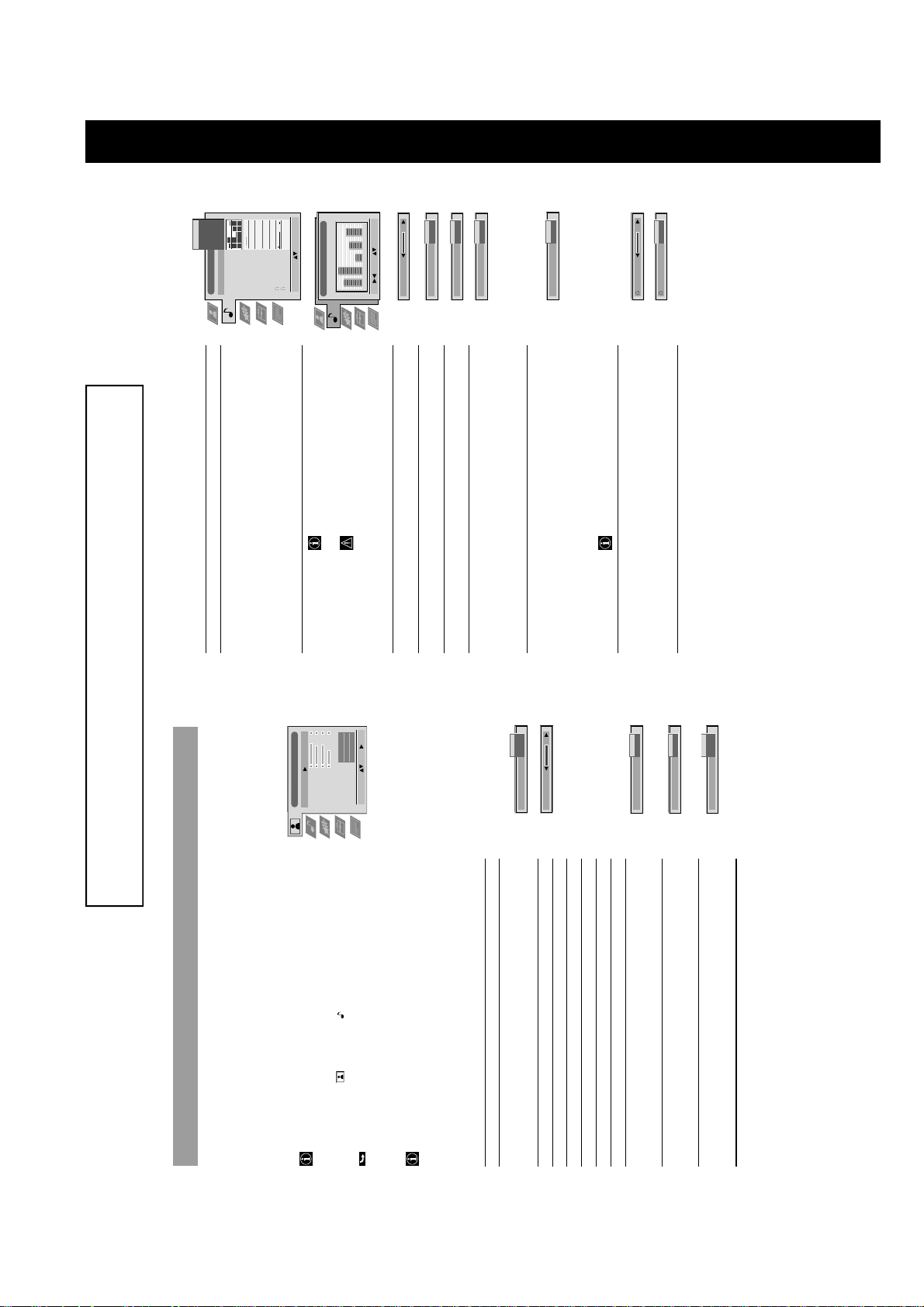
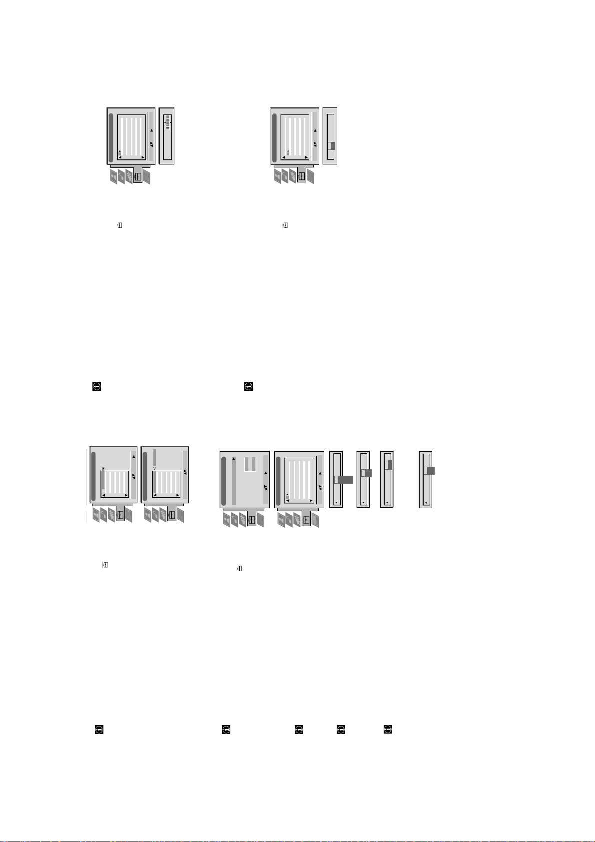
15
When Auto Format in the Features menu is preset to ”Normal“ or “Full“, the
TV set automatically selects the detected screen format. Screen mode, however,
lets you select the screen format of your choice.
Press the button on the remote control repeatedly to get one of the
Operation (TV menu system):
Changing the screen mode
•
Smart
Zoom
bottom of the picture are cut off
following formats:
Smart imitation of wide screen effect for 4:3 broadcasts, parts of the top and
4:3 conventional 4:3 aspect ratio, full picture information
14:9 compromise between 4:3 and 16:9 aspect ratios
Zoom imitation of wide screen effect for letterboxed movies
Wide for 16:9 broadcasts
Wide
In Zoom, Smart and 14:9 modes parts of the top and the bottom of the screen
are cut off. Using 4 and $ you can adjust the position of the image onscreen to
e.g. read subtitles. Press OK to confirm.
TV
Off
Off
On
On
Features
Auto Format
Format Correction
Sleep Timer
Parental Lock
AV 2 Source
Push to z to enter.
Operation (TV menu system):
Using the Features menu
2 Select the desired menu item using $. Push to z to enter.
1 Press the MENU button on the remote control. Select the symbol using $.
Select: Enter:
3 Select the desired setting using 4 or $.
4 Store by pressing OK.
5 Press MENU to return to the normal TV screen.
Off
Full
Normal
Auto Format
according to information from broadcaster.
Features
Item Effect/Operation
Auto Format* 4 Off: Size of picture does not automatically adjust.
*only for aerial signal Normal: Size of picture automatically adjusts
size to eliminate any dark areas on the TV
picture (as shown below):
$ Full: The TV can automatically adjust the picture
Off
On
10 min
Format Correction
Sleep Timer
switches itself into standby mode
10 min.
4 Off
Format Correction* 4 On: Smart mode is selected automatically for
*only if Auto Format is 4:3/14:9 broadcasts
set to ‘Normal‘ or ‘Full‘ $ Off: 4:3/14:9 is selected
Sleep Timer You can select a time period after which the TV
20 min. . .
Off
Parental Look
.
$ 90 min.
Parental Lock 4 Off: Normal mode
TV
AV 1
AV 2
On
$ On: TV can only be switched on out of
AV 3
AV 2 Source
2. In this way you can
j
2/
Y
record from this socket while watching another
source.
AV1 audio/video signal from Scart 1
the buttons on the TV do not work.
You can select the source to be output from the
Scart connector
standby-mode using the Remote Commander,
AV2 audio/video signal from Scart 2
4 TV audio/video signal from the aerial ˘
AV2 Source
$ AV3 audio/video signal from connectors on top or
bottom of rear of TV.
14
10
http://cxema.ru
ARD
BBC
C09
C10
B/G
B/G
Off
Off
Off
Off
Off
Off
Off
Off
Off
Off
Off
1 2 3 4 5 6 7 8 91011
Manual Programme Preset
PROG CHSYSSKIP LABEL
Select: Enter:
C07 TE
Off
SKIP LABEL
6I
PROG CHSYS
BBC1
BBC
C09
C10
I
I
Off
Off
Off
Off
Off
Off
Off
Off
Off
Off
Off
5152535455565758596061
Manual Programme Preset
PROG CHSYSSKIP LABEL
Select: Enter:
17
F189 - - - Off
On
53 I
PROG CHSYSSKIP LABEL
using $.
You can, however, individually name a channel or a video input source.
TV 5
PRO 7
EU-SP
SWF
RTL
C03
C05
C07
C08
C09
1 2 3 4 5 6 7 8 91011
PROG CH LABEL
SAT
MDR
C11
C12
Push to ” to enter.
1 Press the MENU button on the remote control. Select the symbol
DDI
DSF
RTL 2
KAB 1
C13
C14
C15
C16
During tuning the channels are usually labelled automatically.
Naming a channel
Operation (TV menu system):
Programme Sorting
Select Manual Programme Preset using $. Push to ” to enter.
label by pushing to $ or 4. Push repeatedly to ” until the first element of the
2 Select Installation using $. Push to ” to enter.
3 Select the programme position of the channel or the video source you wish to
C03 TV 5
TV 5
PRO 7
EU-SP
SWF
RTL
C03
C05
C07
C08
C09
1 2 3 4 5 6 7 8 91011
PROG CH LABEL
Programme Sorting
Select Prog: Confirm:
position LABEL is highlighted.
Select the other four characters in the same way.
4 Select a number, a letter, + or a blank using 4 or $. Push to ” to confirm.
SAT
MDR
DDI
DSF
RTL 2
KAB 1
C11
C12
C13
C14
C15
C16
Select Position: Move: OK
5 Store your selection by pressing OK.
6 To label other channels or video sources repeat steps 3 to 5.
7 Press MENU to return to the normal TV screen.
channels with the PROGR +/– buttons they then do not appear.
You can, however, still select them using the number buttons.
In case of 100 programme positions there may be unused positions, which
you can skip in the menu »Manual Programme Preset«. When changing
Skipping programme positions
O
Internal
- - - - - - -
Installation
Language/Country
Manual Programme Preset
Select: Enter:
Further Programme Preset
RGB Set Up
Picture Rotation
Speaker Configuration
Personal ID
using $.
Push to ” to enter.
Select Manual Programme Preset using $. Push to ” to enter.
2 Select Installation using $. Push to ” to enter.
1 Press the MENU button on the remote control. Select the symbol
BBC1
BBC
C09
C10
B/G
B/G
Off
Off
Off
Off
Off
Off
Off
Off
Off
Off
Off
1 2 3 4 5 6 7 8 91011
Manual Programme Preset
PROG CHSYSSKIP LABEL
Push to ” to enter.
The column SKIP is highlighted.
3 Select the programme position you wish to skip by pushing to 4 or $.
4 Select ON using $.
5 Store by pressing OK.
6 To skip other programme positions repeat steps 3 to 5.
7 Press MENU to return to the normal TV screen.
CH
F
S
C
I
L
D/K
B/G
EXT
Off
Select: Enter:
SKIP LABEL
PROG CHSYS
Off
SKIP LABEL
1
1 I
PROG SYS
03
SEARCH
CH
Off
SKIP LABEL
1 I
PROG SYS
AV1
AV1
AV2
AV3
Off
SKIP LABEL
0 EXT
PROG CHSYS
using $.
Push to ” to enter.
After tuning in TV channels, you may wish to rearrange the order of the channels.
2 Select Programme Sorting using $. Push to ” to enter.
1 Press the MENU button on your remote control. Select the symbol
Operation (TV menu system):
Sorting TV channels
Push to ” to enter.
3 Select the programme position of the channel you wish to sort using 4 or $.
pressing OK.
The channel is now at the new position. The other programme positions
move accordingly.
4 Move the channel to the new programme position using 4 or $. Store by
5 To sort other programme positions repeat steps 3 to 4.
6 Press MENU to return to the normal TV screen.
using $.
Select Manual Programme Preset using $. Push to ” to enter.
Push to ” to enter.
Use this function to preset channels or a video input source one by one to
programme positions of your choice.
1 Press the MENU button on the remote control. Select the symbol
Manually tuning-in channels
The column SYS is highlighted.
Available TV systems are I for Ireland or EXT for a video input source (please
3 Select the programme position by pushing to 4 or $. Push twice to ”.
2 Select Installation using $. Push to ” to enter.
4 Select the TV system using 4 or $. Push to ” to enter.
go to step 5c after selecting EXT).
5 Select your method for the channel tuning using 4 or $. Push to ” to enter.
11
You have the choice between C for a terrestrial channel, S for a cable channel or
For channel numbers input a two digit number, for the channel frequency a
three digit number.•Select the two or three digits by using the number buttons 0 to 9.
To start the search and to store the channel, press the OK button.
To preset other channels repeat steps 3 to 6a.
F for direct frequency input.
6a Direct Channel Input
Use Search if you do not know the channel number or frequency•Start the search for the next available channel by pushing to $.•Store the channel by pressing OK or continue the search by pushing again to $.•To search for other channels repeat steps 3 to 6b.
b Channel search (SEARCH)
•
•
Select the Video Input source using 4 or $.•Store your selection by pressing OK.•To allocate other sources repeat steps 3 to 5c.
c For video input sources (EXT)
•
6 Press MENU to return to the normal TV screen.
16
http://cxema.ru
ARD
BBC
C09
C10
B/G
B/G
Off
Off
Off
Off
Off
Off
Off
Off
Off
Off
Off
1 2 3 4 5 6 7 8 91011
Manual Programme Preset
PROG CHSYSSKIP LABEL
Select: Enter:
C07 TE
Off
SKIP LABEL
6I
PROG CHSYS
BBC1
BBC
C09
C10
I
I
Off
Off
Off
Off
Off
Off
Off
Off
Off
Off
Off
5152535455565758596061
Manual Programme Preset
PROG CHSYSSKIP LABEL
Select: Enter:
17
F189 - - - Off
On
53 I
PROG CHSYSSKIP LABEL
using $.
During tuning the channels are usually labelled automatically.
You can, however, individually name a channel or a video input source.
TV 5
PRO 7
EU-SP
SWF
RTL
C03
C05
C07
C08
C09
1 2 3 4 5 6 7 8 91011
PROG CH LABEL
Programme Sorting
1 Press the MENU button on the remote control. Select the symbol
SAT
MDR
DDI
DSF
RTL 2
KAB 1
C11
C12
C13
C14
C15
C16
Naming a channel
Operation (TV menu system):
Push to ” to enter.
Select Manual Programme Preset using $. Push to ” to enter.
label by pushing to $ or 4. Push repeatedly to ” until the first element of the
2 Select Installation using $. Push to ” to enter.
3 Select the programme position of the channel or the video source you wish to
C03 TV 5
TV 5
PRO 7
EU-SP
SWF
C03
C05
C07
C08
1 2 3 4 5 6 7 8 91011
PROG CH LABEL
Programme Sorting
Select Prog: Confirm:
position LABEL is highlighted.
4 Select a number, a letter, + or a blank using 4 or $. Push to ” to confirm.
RTL
SAT
MDR
DDI
DSF
RTL 2
KAB 1
C09
C11
C12
C13
C14
C15
C16
Select the other four characters in the same way.
5 Store your selection by pressing OK.
Select Position: Move: OK
6 To label other channels or video sources repeat steps 3 to 5.
7 Press MENU to return to the normal TV screen.
Installation
Language/Country
Manual Programme Preset
using $.
channels with the PROGR +/– buttons they then do not appear.
In case of 100 programme positions there may be unused positions, which
you can skip in the menu »Manual Programme Preset«. When changing
Skipping programme positions
O
Internal
- - - - - - -
Further Programme Preset
RGB Set Up
Picture Rotation
Speaker Configuration
Personal ID
Push to ” to enter.
You can, however, still select them using the number buttons.
2 Select Installation using $. Push to ” to enter.
1 Press the MENU button on the remote control. Select the symbol
BBC1
BBC
C09
C10
B/G
B/G
Off
Off
Off
Off
Off
Off
Off
1 2 3 4 5 6 7 8 91011
Select: Enter:
Manual Programme Preset
PROG CHSYSSKIP LABEL
Select Manual Programme Preset using $. Push to ” to enter.
Push to ” to enter.
The column SKIP is highlighted.
3 Select the programme position you wish to skip by pushing to 4 or $.
L
B/G
Off
Off
Off
Off
Off
SKIP LABEL
Select: Enter:
1
PROG CHSYS
4 Select ON using $.
I
D/K
5 Store by pressing OK.
EXT
6 To skip other programme positions repeat steps 3 to 5.
7 Press MENU to return to the normal TV screen.
03
CH
CH
F
S
C
Off
SKIP LABEL
Off
SKIP LABEL
1 I
1 I
PROG SYS
PROG SYS
SEARCH
AV1
AV1
AV2
AV3
Off
SKIP LABEL
0 EXT
PROG CHSYS
Operation (TV menu system):
Sorting TV channels
using $.
Push to ” to enter.
After tuning in TV channels, you may wish to rearrange the order of the channels.
2 Select Programme Sorting using $. Push to ” to enter.
3 Select the programme position of the channel you wish to sort using 4 or $.
1 Press the MENU button on your remote control. Select the symbol
Push to ” to enter.
4 Move the channel to the new programme position using 4 or $. Store by
pressing OK.
The channel is now at the new position. The other programme positions
move accordingly.
5 To sort other programme positions repeat steps 3 to 4.
using $.
Push to ” to enter.
Use this function to preset channels or a video input source one by one to
programme positions of your choice.
6 Press MENU to return to the normal TV screen.
Manually tuning-in channels
2 Select Installation using $. Push to ” to enter.
1 Press the MENU button on the remote control. Select the symbol
Select Manual Programme Preset using $. Push to ” to enter.
The column SYS is highlighted.
Available TV systems are I for Ireland or EXT for a video input source (please
go to step 5c after selecting EXT).
3 Select the programme position by pushing to 4 or $. Push twice to ”.
4 Select the TV system using 4 or $. Push to ” to enter.
5 Select your method for the channel tuning using 4 or $. Push to ” to enter.
12
You have the choice between C for a terrestrial channel, S for a cable channel or
For channel numbers input a two digit number, for the channel frequency a
three digit number.•Select the two or three digits by using the number buttons 0 to 9.
To start the search and to store the channel, press the OK button.
To preset other channels repeat steps 3 to 6a.
F for direct frequency input.
6a Direct Channel Input
Use Search if you do not know the channel number or frequency•Start the search for the next available channel by pushing to $.•Store the channel by pressing OK or continue the search by pushing again to $.•To search for other channels repeat steps 3 to 6b.
b Channel search (SEARCH)
•
•
Select the Video Input source using 4 or $.•Store your selection by pressing OK.•To allocate other sources repeat steps 3 to 5c.
c For video input sources (EXT)
•
6 Press MENU to return to the normal TV screen.
16
http://cxema.ru
O
22
Smartlink
Smartlink is a direct link between your TV set and a VCR.
For Smartlink you need:
A VCR which supports Smartlink, NexTView Link, Easy Link or Megalogic.
A fully-wired 21-pin SCART cable to connect your VCR to Scart
Y
2/
j
2
connector.
The features of Smartlink are:
Tuning information such as the channel overview are downloaded from
the TV set to the VCR.
With NexTView you can programme your VCR easily.Direct TV recording: While watching TV you just need to press just one button
on the VCR to record this programme.
For more information on Smartlink please refer to the Instruction Manual of
your VCR.
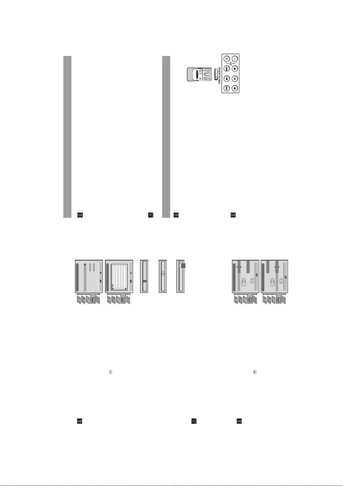
Remote control of other Sony equipment
Using the buttons underneath the cover of the remote control you can
control other Sony equipment.
1 Open the cover of the remote control.
2 Set the selector VTR 1234 DVD according to the equipment you want to control:
VTR 1 Beta VCR
VTR 2 8 mm VCR
VTR 3 VHS VCR
VTR 4 Digital Video (DCR-VX 1000/9000 E, VHR-1000)
DVD Digital Video Disk
3 Use the buttons on the remote control to operate the equipment.
If your video equipment has a COMMAND MODE selector, set this
selector to the same position as the VTR 1234 DVD selector on the
TV remote control.If the equipment does not have a certain function, the corresponding
button on the remote control does not work.
Optional Equipment
Internal
- - - - - - -
Installation
Language/Country
Manual Programme Preset
Further Programme Preset
RGB Set Up
Picture Rotation
Speaker Configuration
manual fine tuning.
Using the menu Further Programme Preset you can
a) individually adjust the volume level of each channel.
b) improve the quality of a weak channel (picture or sound distortions) with
Using the Further Programme Preset function
Operation (TV menu system):
Off
Off
Off
OnOnOn
Personal ID
000
1 2 3 4 5 6 7 8 91011
Select: Enter:
Further Programme Preset
PROG AFTVOL DECODER
Select: Enter:
PROG AFTVOL DECODER
0
1
using $. Push to ” to enter.
scrambled signals (e.g. from a Pay TV decoder). In this way a connected
Smartlink VCR records the unscrambled signal.
c) preset the AV output for programme positions of those channels with
1 Press MENU. Select the symbol
2 Select Installation using $. Push to ” to enter. Select Further Programme Preset
Push repeatedly to ” to select:
using $. Push to ” to enter.
3 Select the programme position of the desired channel by pushing to 4 or $.
VOL (Volume Offset), AFT (Automatic Fine Tuning) or DECODER.
The selected item changes colour.
4a VOL
Off
AV1
AV2
On
1 -5
PROG AFTVOL DECODER
Push to 4 or $ to adjust the volume level (range -7 to +7) of the channel.
Store by pressing OK.
Repeat steps 3 and 4a if you wish to adjust the volume level of other channels.
b AFT
1 -5 On
PROG AFTVOL DECODER
Push to 4 or $ to fine tune the channel (range -15 to +15). Store by pressing OK.
Repeat steps 3 and 4b if you wish to fine tune other channels.
Push to 4 or $ to select AV1 (Euro AV socket 1) or AV2 (Euro AV socket 2) as
output for the video source on this programme position. Store by pressing OK.
Repeat steps 3 and 4c if you wish to preset the AV output of other video sources.
Should you use Auto Tuning afterwards, this setting will
c DECODER
be cancelled.
5 Press MENU to return to the normal TV screen.
RGB Set Up
When connecting an RGB source such as a Sony playstation you may need to
Adjusting the picture geometry for an RGB source
H CentreOH Size
O
RGB Set Up
Adjust Position: Confirm: OK
using $. Push to ” to enter.
readjust the picture geometry.
3 Select Installation using $. Push to ” to enter. Select RGB Set Up using $.
1 Select the connected RGB source … 1 by pressing … repeatedly.
2 Press MENU. Select the symbol
H CentreOH Size
Push to ” to enter.
4 Select H Centre by pushing to ”. Adjust the centre of the picture
O
(range from -10 to +10) using 4 or $. Store by pressing OK.
(range from -10 to +10) using 4 or $. Store by pressing OK.
5 Select H Size using $. Push to ” to enter. Adjust the horizontal coordinates
Adjust Size: Confirm: OK
6 Press MENU to return to the normal TV screen.
18
13
http://cxema.ru
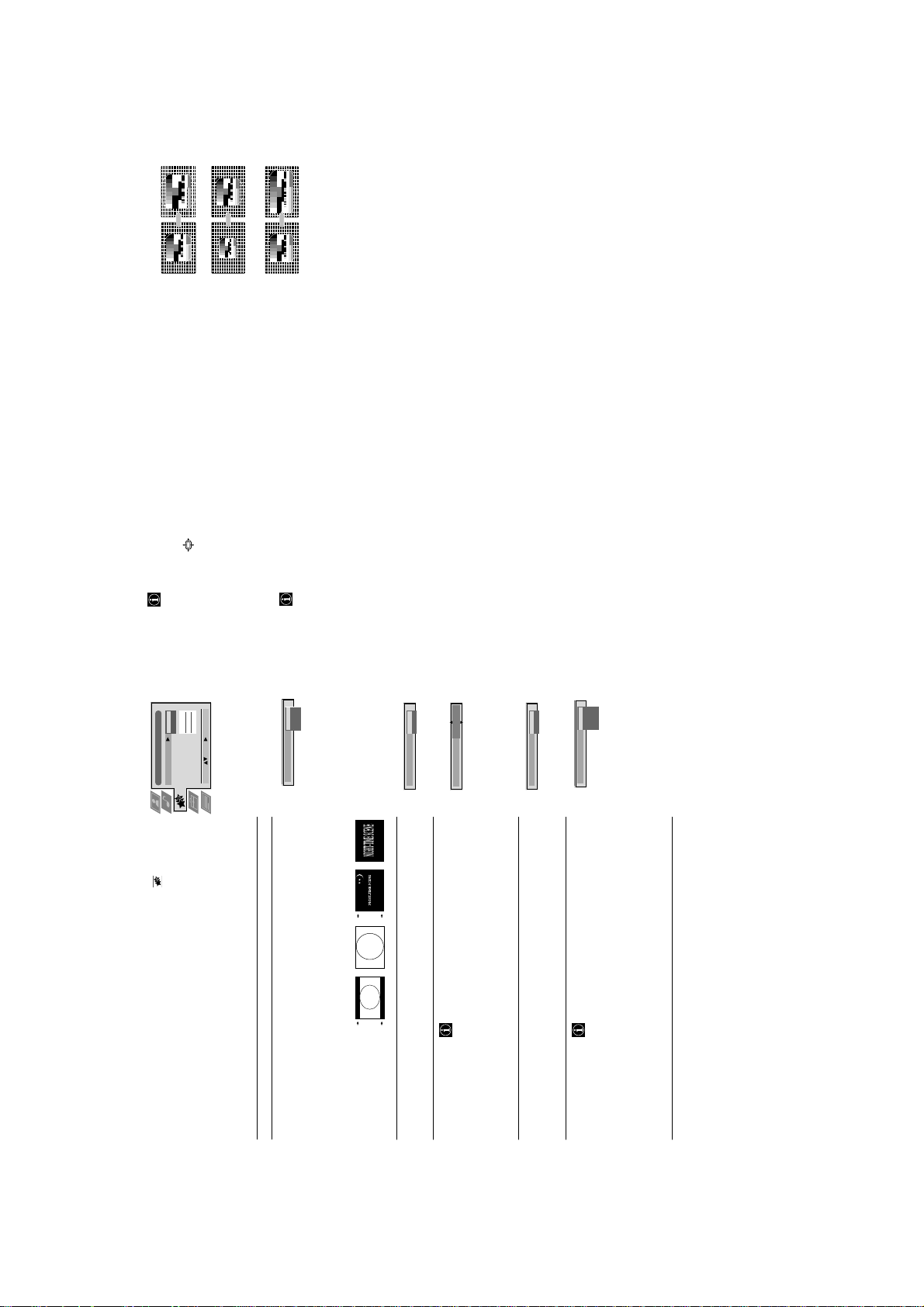
11
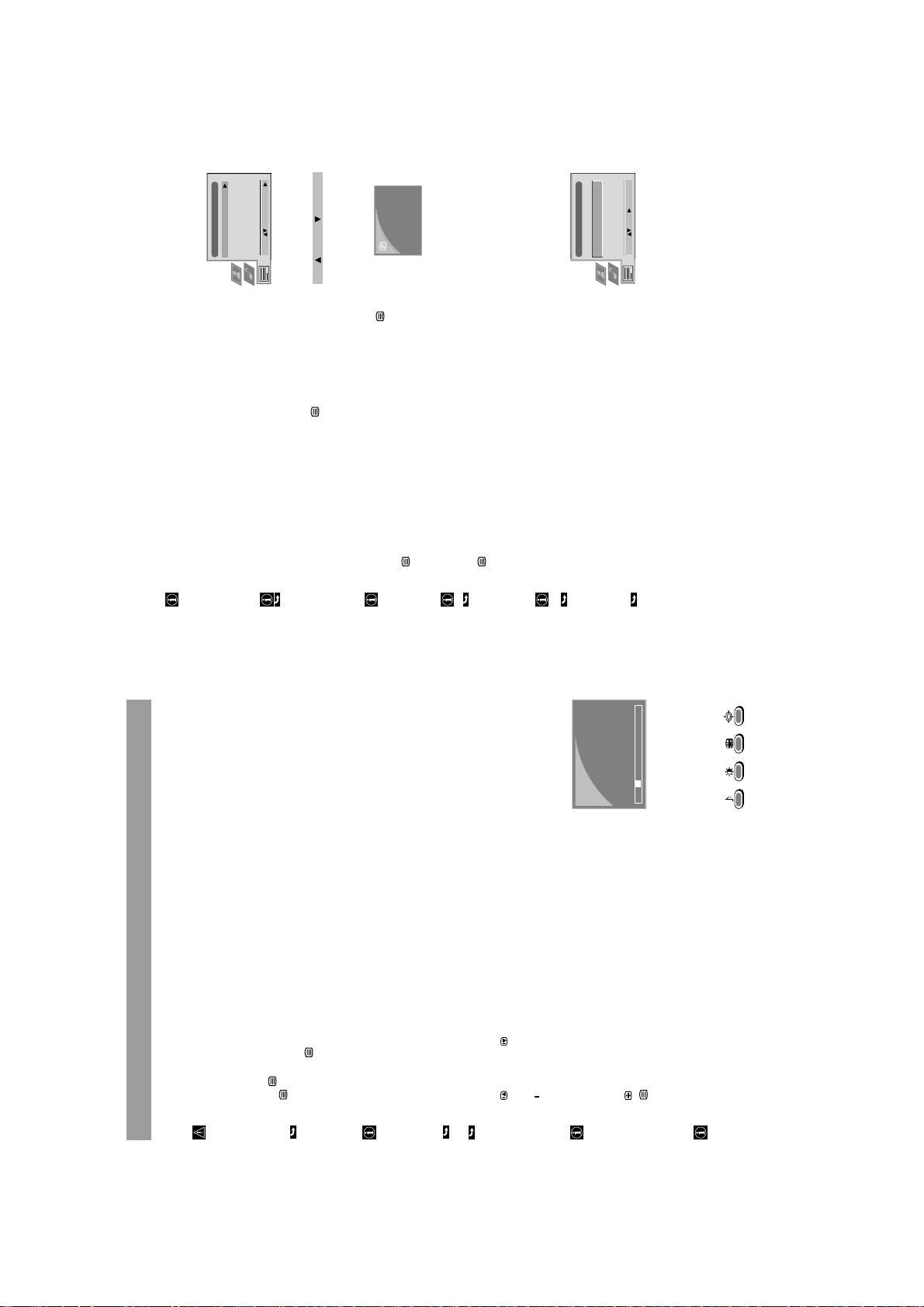
This TV set has a menu-guided teletext system. When teletext is switched on
Using the Teletext menu
Operation
Teletext
you can use the joystick buttons to operate the teletext menu.
Select the menu functions as follows:
1 Press the MENU button on the remote control to display the Teletext menu.
Top / Bottom / Full
Text Clear
Reveal
Time Page
2 Select the teletext function using 4 or $. Push to ” to enter.
Top/Bottom/Full
Select: Enter Menu:
For convenient reading of a Teletext page you can enlarge it.
is displayed.
After having selected the function, a sub menu Top 4 Bottom $ Full OK
Top: Bottom: Full: OK
to resume the normal
Push to 4 to enlarge the upper half of the screen, push to $ to enlarge the lower
half. Press OK to resume the normal size. Press
Teletext operation.
•
After having selected the function, you can watch a TV channel while waiting
for a requested Teletext page. As soon as the page is available, the symbol
Text Clear
changes colour.•Press to view the page.
Some teletext pages contain hidden information (e.g., for a quiz), which you can
reveal.
Reveal
Time Page
After having selected the function, the hidden information appears.
Press to resume the normal Teletext operation.
•
You can call up a time-coded page - such as an alarm page - at a time specified
by you.
After having selected the function a sub menu is displayed.
Time Page*
*depending on availability of service
1 Select On using 4 or $. Push to ” to enter.
Select: Enter:
PAGE TIME
– – – - - : - -
The time is displayed in the top left-hand corner of the screen.
At the requested time the page is displayed.
2 Enter the three digits of the desired page using the number buttons.
3 Enter the four digits of the desired time using the number buttons.
4 Press OK to store.
Teletext
Operation
button once on your remote control to switch Teletext on.
again for Mix mode.
or press a third time to switch teletext off.
;
Please use a TV channel with a strong signal, otherwise there may be
Teletext errors.
Most TV channels broadcast information via teletext. The index page of the teletext
service (usually page 100) gives you information on how to use the service.
Switching Teletext on and off
1 Select the TV channel which carries the teletext service you want to view.
b Press
2a Press the
The TV broadcast and the Teletext display are overlapped.
3 Press
Selecting a Teletext Page
If you have made a mistake:
Type in any three digits, then re-enter the correct page number.
Input the three digits of the page number using the number buttons on your remote
Page Catching
control.
1 Using the number buttons on the remote control, select a teletext page which
216-02
.
+
has several page numbers on it (e.g. the index page).
Page Catching is displayed.
The requested page is displayed after some seconds.
Press (Page +) or (Page -).
Press
A teletext page may consist of several subpages. In this case an information line
is displayed, showing the number of subpages.
Select the mode by pushing to 4. Select the subpage by using 4 or $.
•
Selecting a subpage
2 Press the OK button.
3 Select the desired page number using 4 or $ then press the OK button.
•
•
Selecting the next or the preceding page
Selecting the index page
14
01 03 04 05 06 07 0802
to resume normal teletext reception.
2 Press
Freezing a Teletext subpage
1 Press to freeze the Teletext page.
Using Fastext*
*depending on availability of service
Fastext lets you access pages with one button stroke. When Fastext is broadcast,
a colour-coded menu appears at the bottom of the screen. The colours of this
menu correspond to the red, green, yellow and blue buttons on the remote
control.•Press the coloured button which corresponds to the colour in the
colour-coded menu.
10

http://cxema.ru
Troubleshooting
Here are some simple solutions to problems which may affect the picture and sound.
Additional Information
Problem Solution
, PROGR+/-
;
or one of the numbered buttons on the remote control.)
• Check the aerial connection.
• Press U on the TV. (If u indicator is on, press
No picture (screen is dark), no sound • Plug the TV in.
button.
¤
and adjust Brightness, Contrast
is displayed on the screen, press
• Check if the selected video source is on.
• Turn the TV off for 3 or 4 seconds and then turn it on again using U .
¤
• If
Poor or no picture (screen is dark), • Press MENU. Select
but good sound and Colour.
Good picture, but poor or no sound • Press ¸ + .
No colour for colour programmes • Open the cover of the remote control. Press ? button.
Remote control does not function • Replace the batteries.
Control Panel does not function • Make sure Parental lock is Off.
discharge to occur.
Channel Guide
TV System Receivable Channels Channel Display
B/G/H E2 .. 12, 21 .. 69 C02 C03 C04 .. C12 C21 .. C69
TV Cable (1) S1 .. 41 S01 S02 .. S41
TV Cable (2) S01 .. S05, M1 .. M10, U1 .. U10 S42 .. S46 S01 .. S10 S11 .. S20
Italy A B C D E F G H H1 H2, 21 .. 69 C13 C14 C15 C16 C17 C18 C19 C20 C11 C12, C21-C69
D/K R01 .. R12, R21 .. R69 C01 .. C12 C21 .. C69
TV Cable (1) S01 S02 .. S41
TV Cable (2) S42 S43 .. S46
TV Cable B .. Q*, S21 .. F41 S02, S03 .. S17, S21 .. S41
Note: As with some other electrical appliances under certain circumstances there is potential for small electrostatic
If you continue to have problems, have your TV serviced by qualified personnel. Never open the casing yourself.
L F2 .. F10 F21 .. F69 C01 .. C12, C21 .. C69
I B21 .. B68 C21 .. C68
* If channels B..Q are available, the display S02-S17 will appear on the screen.
24
23
2 x 25W (music power),
2 x 15W (RMS)
Sound output Right and left speaker
Specifications
Additional Information
Television B/G/H, D/K, I, L
Power KV-28FC60/28FC60-Z: 132 W
system
Colour PAL, SECAM, NTSC 3.58/4.43 (via Video In)
system
772(w) x 497(h) x 533(d) mm
KV-32FC60/32FC60-Z
867(w) x 564(h) x 558(d) mm
consumption KV-32FC60/32FC60-Z: 130 W
Dimensions KV-28FC60/32FC60-Z
KV-28FC60/28FC60-Z
Channel See Channel Guide on next page
coverage
Picture tube FD Trinitron
Weight KV-28FC60/28FC60-Z
Approx. 71 cm (28 inches)
Approx. 42.5 kg
KV-32FC60/32FC60-Z
Approx. 65 kg
Approx. 66 cm picture measured diagonally
102° deflection
KV-32FC60/32FC60-Z
Approx. 82 cm (32 inches)
1 Instruction Manual
Accessoires 1 Remote Control RM-892
supplied 2 Batteries
1/ 1: 21-pin scart connector
Approx. 76 cm picture measured diagonally
102° deflection
Y
Sockets
15
noise reduction, 100 Hz picture,
graphic equaliser, personal ID,
sleep timer, NexTView, NICAM
stereo, Digital Comb Filter
Other Features Flat display Trinitron tube, digital
2:21-pin scart connector
3:21-pin scart connector
j
j
2/
output of TV signals
(Rear) input of audio/video or RGB signals
3/
input of audio/video or S-video signals
selectable output of audio/video signals
Y
Y
R/D/D/D variable output for audio signals
L/G/S/I RCA-connectors,
input of audio/video or S-video signals
output of audio/video signals (monitor out)
|
3 Phono jacks
Headphones jack -stereo minijack
input of audio signals
≤
External speaker terminals:2-pin DIN (2)
q 3 : 4-pin DIN
input of S-video signals
…3 Phono jack
input of video signals
2
Sockets
(Front)

http://cxema.ru
SECTION 2 DISASSEMBLY
2-1. Rear Cover Removal
Remove the rear cover fixing screws indicated. Take care
when removing the rear cover not to damage the speaker
cables [Disconnect the speaker connector] as speakers are
fitted inside the rear cover.
2-2. Speaker Connector Disconnection
Before completely removing the rear cover disconnect the
speaker connector.
2-3. Chassis Removal and Refitting
To remove lift the main bracket rear slightly and slide the
chassis away from the beznet. Ensure that the interconnecting
leads are released from their purse locks to prevent damage
being caused.
When refitting the chassis ensure that the main
bracket is located in the beznet guide slots before
sliding the chassis forwards. Refit the
interconnecting leads in their respective purse locks.
16
http://cxema.ru
2-4. Service Position 2-5. D1 Board Removal
Position the PWB as indicated to access the solder side.
To gain access to the D Board follow the instructions on page
19. [Removal and Replacement of the main bracket bottom
plates ].
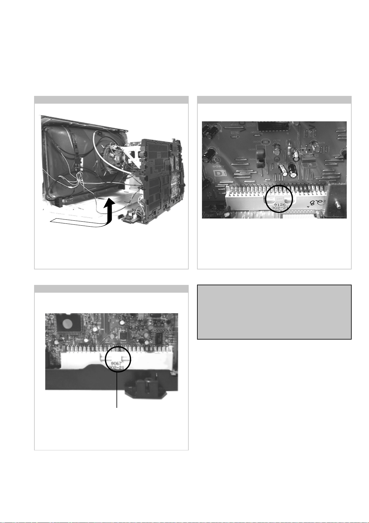
2-6. J Board Removal
Release the clip and carefully remove the board in a vertical
direction.
To remove the D1 Board release the clip circled and gently
remove the board in a vertical direction.
Note :
Removal of the B1, E, M, and U printed circuit boards follows
the same procedure of releasing the securing clips as indicated
in the figs for D1 and J board removal.
Take care not to apply to great a pressure to the clips as this
may cause damage.
17
http://cxema.ru
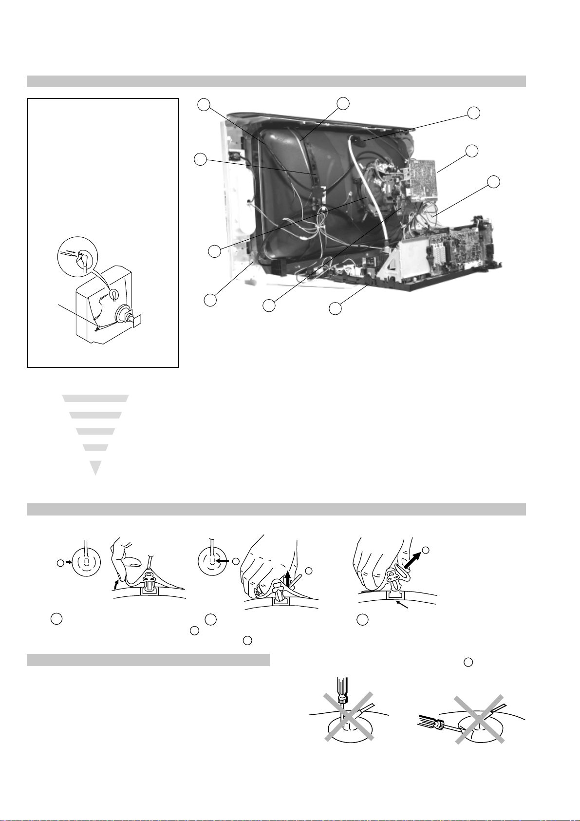
2-7. Picture Tube Removal
WARNING:
BEFORE REMOVING
THE ANODE CAP
High voltage remains in the CRT even
after the power is disconnected. To
avoid electric shock, discharge CRT
before attempting to remove the anode
cap. Short between anode and CRT
coated earth ground strap.
Coated Earth
Ground Strap
8
9
1
3
7
2
6
10
5
4
1. Discharge the anode of the CRT and remove the anode cap.
2. Unplug all interconnecting leads from the Deflection yoke, neck
assy, degaussing coils and CRT grounding strap.
3. Remove the C Board from the CRT.
4. Remove the chassis assembly.
5. Loosen the Neck assembly fixing screw and remove.
6. Loosen the Deflection yoke fixing screw and remove.
7. Place the set with the CRT face down on a cushion and remove
the Degaussing Coil holders.
8. Remove the Degaussing Coils.
9. Remove the CRT grounding strap and spring tentioners.
10. Unscrew the four CRT fixing screws [ located on each CRT
corner ] and remove the CRT.
[Take care not to handle the CRT by the neck.]
Removal of the Anode-Cap
* REMOVING PROCEDURES.
a
1
Turn up one side of the rubber cap in
the direction indicated by the arrow a
b
2 Using a thumb pull up the rubber cap
firmly in the direction indicated by the
arrow b
How to handle the Anode-Cap
1. To prevent damaging the surface of the anode-cap do not use
sharp materials.
2. Do not apply too great a pressure on the rubber, as this may cause damage
to the anode connector.
3. A metal fitting called a shatter hook terminal is fitted inside the rubber
cap.
Do not turn the rubber foot over excessively, this may cause damage if the
shatter hook sticks out.
c
b
Anode button
3 When one side of the rubber cap is
separated from the anode button, the
anode-cap can be removed by turning
up the rubber cap and pulling it up in
the direction of the arrow c
18
http://cxema.ru
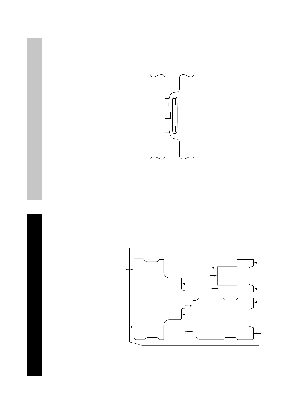
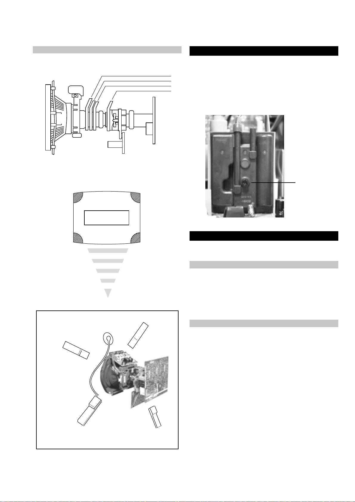
For safety reasons, on no account should the plates be
removed and not refitted after servicing.
Catch
Tab
£
Because the plates differ in size it is important that the correct plates are refitted in their
original location.
Please note that the plates need to be rotated 180 degrees from their cut position to allow the
(2) REFITTING THE PLATES
tabs to be fitted into their catch positions.
REMOVAL AND REPLACEMENT OF THE MAIN-BRACKET
BOTTOM PLATES.
Only remove the necessary plate to gain access to the printed wiring board.
In the event of servicing being required to the solder side of the D Board printed wiring
board, the bottom plates fitted to the main chassis bracket require to be removed.
This is performed by cutting the gates with a sharp wire cutter at the locations indicated by
the arrows.
(1) REMOVING THE PLATES
Note : There are 4 plates fitted to the main bracket and secured by 4 gates.
19
http://cxema.ru
SECTION 3 SET-UP ADJUSTMENTS
Neck assy
Align the bottom edge
of the neck assy with
the G3 hole centre
• When complete readjustment is necessary or a new picture tube is
installed, carry out the following adjustments.
• Unless there are specific instructions to the contrary, carry out
these adjustments with the rated power supply.
• Unless there are specific instructions to the contrary, set the
controls and switches to the following settings :
Contrast .................................. normal
Brightness .................................. normal
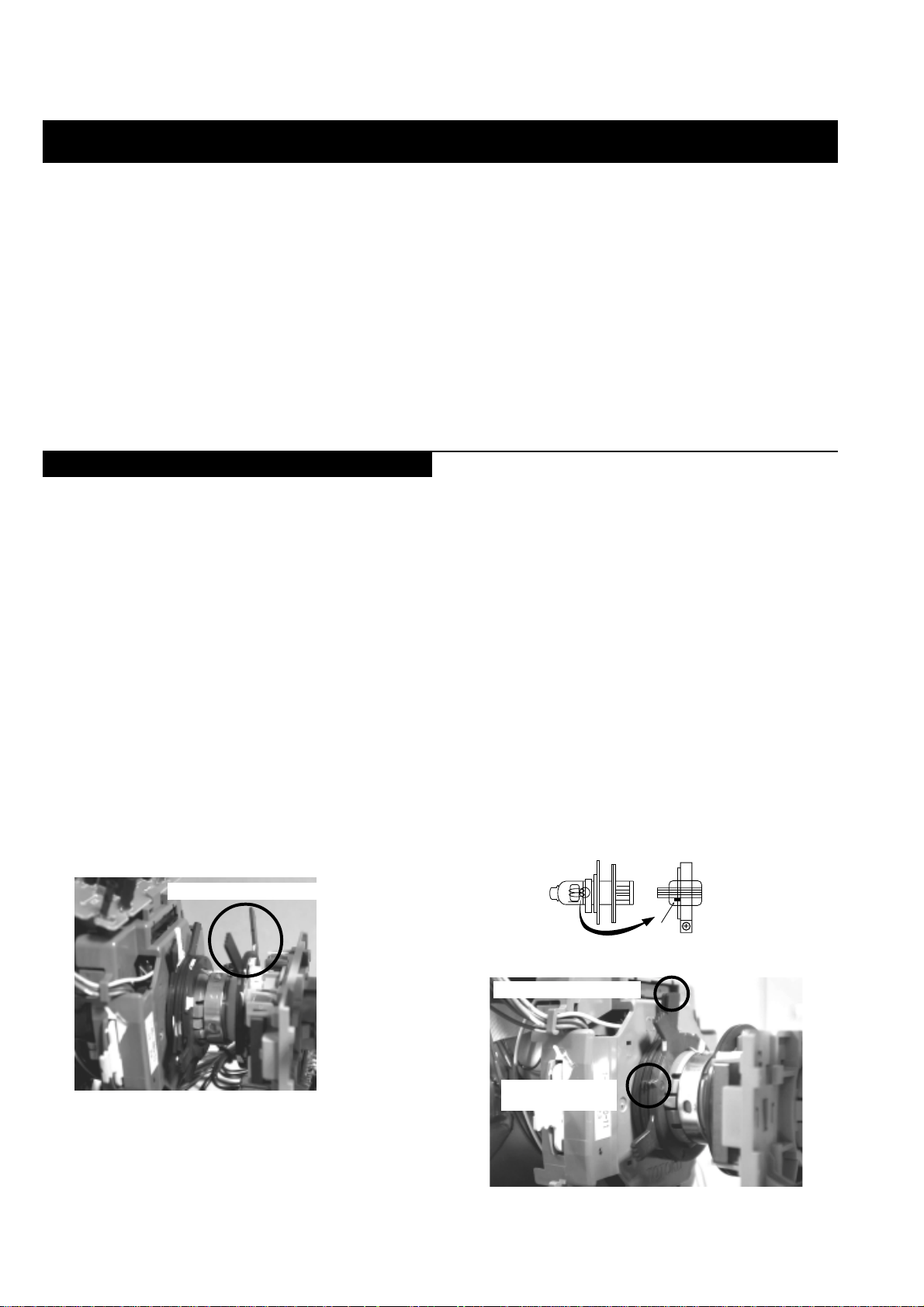
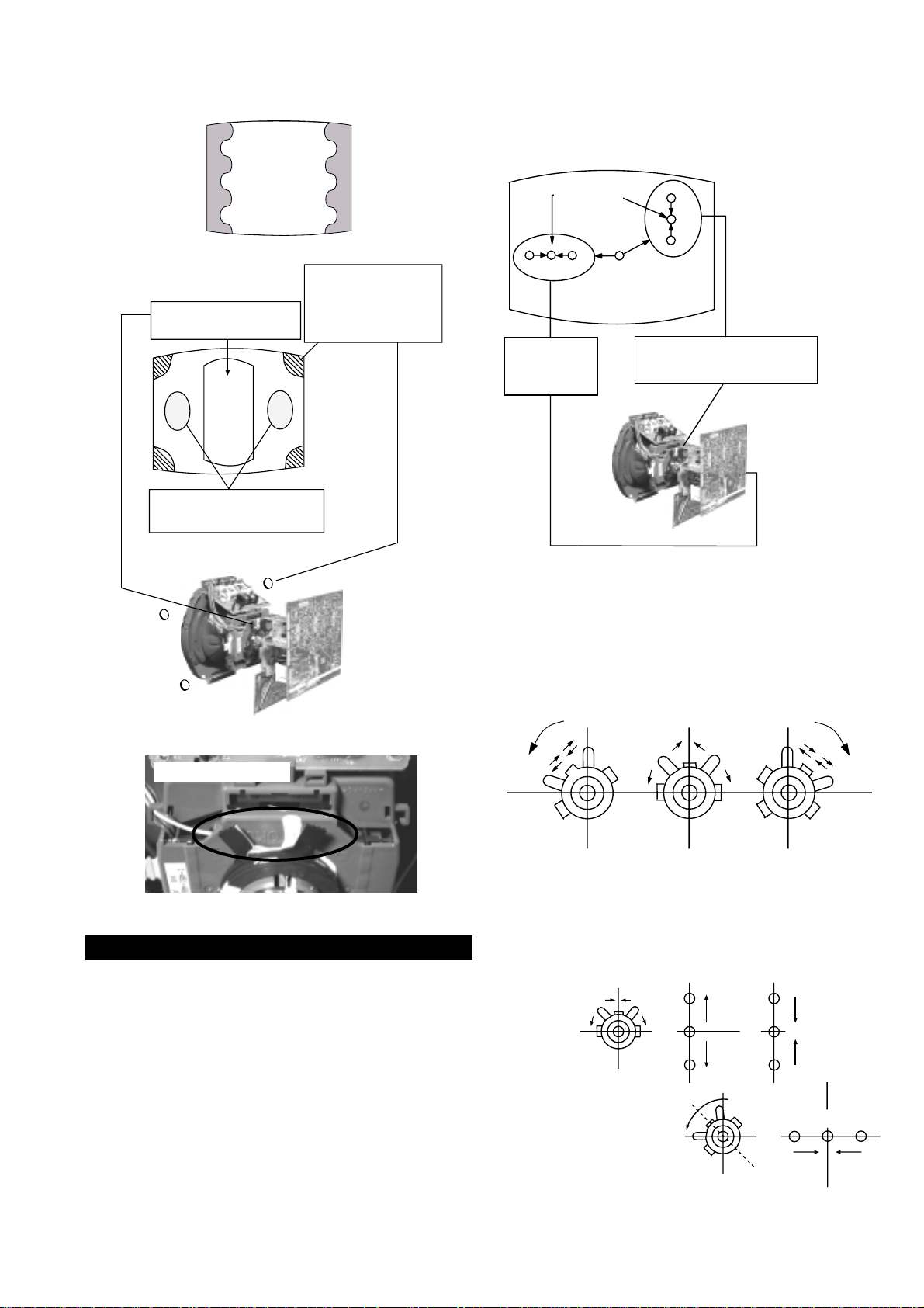
3-1. Beam Landing
Preparation :
1. In order to reduce the influence of geomagnetism on the set’s
picture tube, face it in an easterly or westerly direction.
2. Switch on the TV set’s power and degauss with a degausser.
(1) Adjustment of Correction Magnet for Y-Splitting Axis.
1. Input a crosshatch signal from the pattern generator.
2. Set the Picture control to minimum and confirm that the
Brightness control is set to normal.
3. Position the neck assembly as indicated in Fig.3-2.
4. Loosen the deflection yoke fixing screw.
5. Move the deflection yoke as far forward as is possible.
6. Adjust the upper and lower pin symmetrically by opening or
closing the Y-splitting axis correction magnets located on the neck
assembly.
7. Return the deflection yoke to its original position and re-tighten its
fixing screw.
Fig.3-1
Carry out the adjustments in the following order :
3-1. Beam Landing.
3-2. Convergence.
3-3. Focus.
3-4. White Balance.
Note : Test equipment required.
1. Color bar/pattern generator.
2. Degausser.
3. Oscilloscope.
4. Digital multimeter.
(2) Landing
Note : Before carrying out the following adjustments adjust the
magnets as indicated below [See Fig.3-3].
1. Input an all-white signal from the pattern generator.
Maximize the picture setting and adjust the Brightness setting.
2. Rough-adjust the focus and horizontal convergence.
3. Loosen the deflection yoke screws and align the purity adjustment
knob to its central position. [See Fig.3-3].
4. Switch from the all-white pattern to an all-green pattern.
5. Move the deflection yoke backwards and adjust with the purity
magnet so that the green is at the centre and it aligns
symmetrically [See Fig.3-4].
6. Move the deflection yoke forward and adjust so that the entire
screen becomes green.
7. Switch the raster signal to red, then to blue and verify the landing
condition.
8. When the position of the deflection yoke has been determined,
fasten the deflection yoke with its fixing screw.
9. If the beam does not land correctly in all the corners of the screen,
use magnets to correct it.
Fig.3-2
Y-splitting axis correction magnet
Caution :
High voltages are present on the Deflection yoke terminals - take care
when handling the Deflection yoke whilst carrying out adjustments.
20
Fig.3-3
Purity magnets
Align pips on
each magnet
Align both Purity magnets
to the vertical position
http://cxema.ru
B
GR
(
Open
)
(
Close
)
Fig.3-4
GREEN
RED
BLUE
Disk magnets or
rotatable disk
Purity control corrects
this area
ab
magnets correct
these areas (a-d)
Center dot
H.STAT
convergence
control
V.STAT
Vertical Static Magnet
c
Deflection yoke positioning
corrects these areas
Disk Magnets
Purity control magnets
d
RV5375 (H STAT)
H STAT Convergence
(on mount side)
If the horizontal dots are unable to coincide with the variable
range of the H.STAT convergence, adjust together with the
V.STAT convergence whilst tracking.
[Adjust the convergence by tilting the V.STAT convergence or by
opening and closing the V.STAT convergence.]
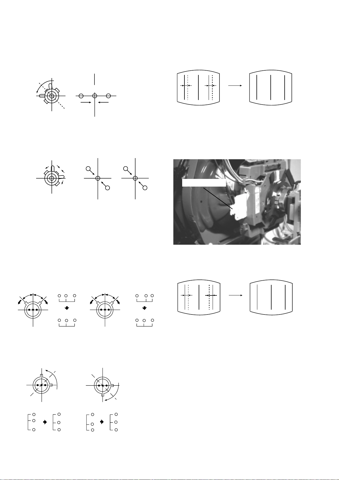
3-2. Convergence
(1) Screen centre convergence [Static convergence]
1. Input a dot pattern signal from the pattern generator.
2. Normalize the picture setting.
3. [Moving horizontally], adjust the H.STAT control so that the
horizontal red, green and blue dots coincide at the centre of the
screen.
4. [Moving horizontally], adjust the V.STAT magnet so that the
vertical red, green and blue dots coincide at the centre of the
screen.
4. Movement of the red, green and blue dots by tilting the V.STAT
magnet and by opening or closing the V.STAT magnet.
a). By opening or closing the V.STAT magnet, the red green and blue
dots move in the direction indicated below.
B
G
R
b). By rotating the V.STAT
magnet counter clockwise,
the red, green and blue
dots move as indicated.
B
G
R
21
http://cxema.ru
c). By rotating the V.STAT magnet clockwise, the red, green and blue
dots move in the direction indicated below.
B
GR
HAMP
d). By opening or closing the V.STAT magnet, the red green and blue
dots move in the direction indicated below.
R
G
B
Note : If the blue dot does not coincide with the red and green points,
correct the points by using the BMC [Hexapole] magnet.
5. Correction for HMC [Horizontal mis-convergence] and VMC
[Vertical mis-convergence] by using the BMC [Hexapole]magnet.
a). HMC correction by BMC [Hexapole] magnet and movement of
the electron beam.
HMC correction(A) HMC correction(B)
A < B
RG B
B
A > B
G
R
RGB
7. HTIL correction can be performed by adding a THL correction
assembly to the Deflection yoke.
THL Correction assy
HTIL
A = B
RG B
b). VMC correction by BMC [Hexapole] magnet and movement of
the electron beam.
VMC correction(A) VMC correction(B)
C < D
C
D
C = D C > D C = D
R
G
B
R
C
G
D
B
R
G
B
A = B
R
G
B
RG B
22
http://cxema.ru
Layout of each control
Purity magnet
BMC (Hexaploe) magnet
V STAT convergence magnet
Y-splitting axis correction magnet
Note : If you are unable to adjust the corner convergence properly,
this can be corrected with the use of permalloy magnets.
3-3. Focus Adjustment
1. Receive a television broadcast signal.
2. Normalize the picture setting.
3. Adjust the focus control located on the flyback transformer to
obtain the best focus at the centre of the screen.
Bring only the centre area of the screen into focus, the magentaring appears on the screen. In this case, adjust the focus to
optimize the screen uniformly.
Focus
Control
a
a-d: screen-corner
convergence defect
c
Install the permalloy assembly
for the area that needs correcting.
b
Permalloy Assy
X-4387-214-1.
d
Convergence adjustment with permalloy
b
d
3-4. Screen (G2), White Balance
[Adjustment in the service mode using the remote
commander]
G2 adjustment [RV5376]
1. Input a dot signal from the pattern generator.
2. Set the Picture, Brightness and Colour to minimum.
3. Apply 175V DC from an external power supply to the R, G and B
cathodes of the CRT.
4. Whilst watching the picture, adjust the G2 control RV5376
[SCREEN] located on the C Board to the point just before the
flyback return lines disappear.
a
White balance adjustment for TV mode
1. Input an all-white signal from the pattern generator.
2. Enter into the ‘Service Mode’ by pressing ‘TEST’, ‘TEST’ and
‘MENU’ ‘MENU’ on the Service Commander.
3. Select ‘Backend’ from the on screen menu display and press
‘OK’.
4. The ‘Backend’ menu will appear on the screen.[See Page 26]
5. Set the ‘Contrast’ to MAX.
6. Set the ‘R-Drive’ to 41.
7. Adjust the ‘G-Drive’ and the ‘B-Drive’ so that the white
balance becomes optimum.
8. Press the ‘OK’ button to write the data for each item.
9. Set the ‘Contrast’ to MIN.
10. Set the ‘R-Cutoff’ to 31.
11. Adjust the ‘G-Cutoff’, and the ‘B-Cutoff’ with the left and
right buttons on the remote commander so that the white balance
becomes optimum.
c
12. Press the ‘OK’ button to write the data for each item.
23
http://cxema.ru
SECTION 4 CIRCUIT ADJUSTMENTS
4-1. Electrical Adjustments
Service adjustments to this model can be performed using the supplied Remote Commander RM-892.
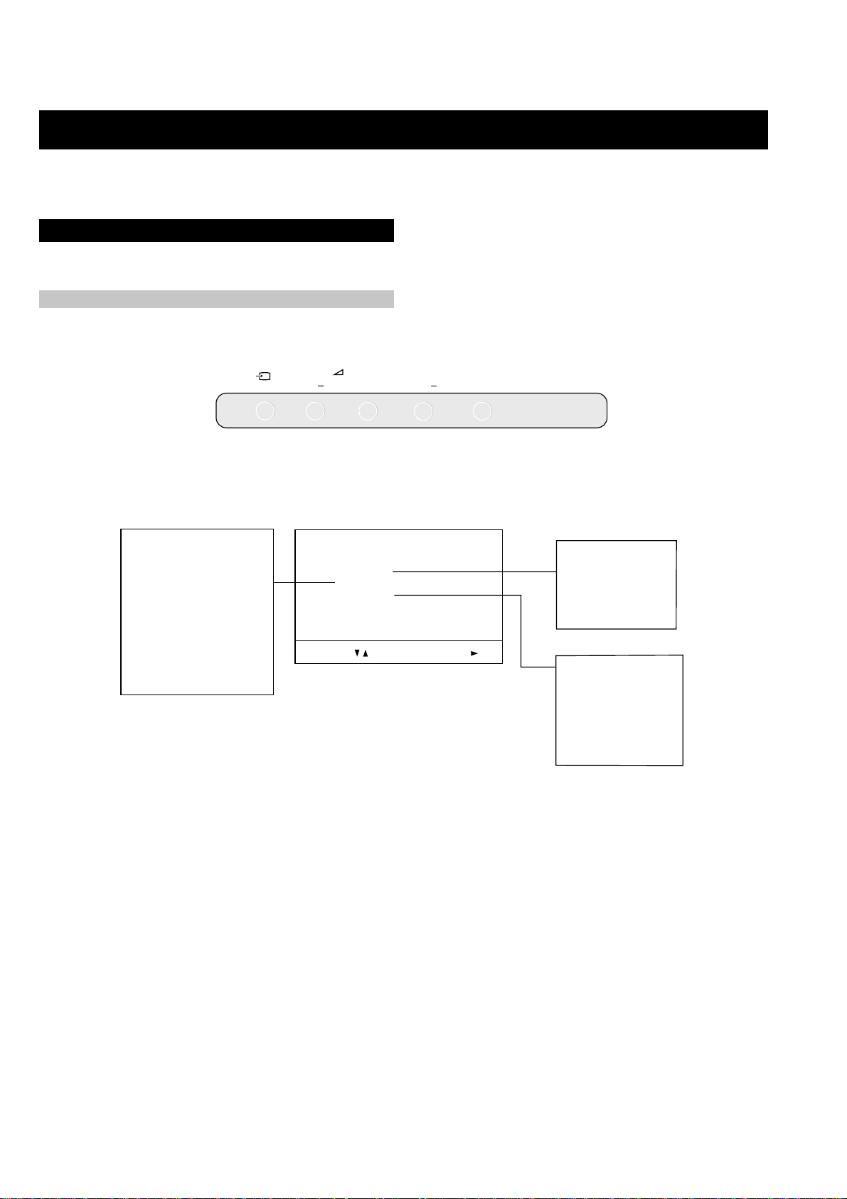
How to enter into the Service Mode
1. Turn on the main power switch of the set while pressing PROG + (plus) and PROG - (minus) buttons on the top control panel.
+
PROGR
+
CONTROL
2. ‘TT’ will appear in the upper right corner of the screen.
3. Press the ‘MENU’ button twice on the remote commander to obtain the service menu on the screen.
RESET DEVICES
Backend
Deflection
Ext Deflection
Dynamic Convergence
Colour Decoder 1
Feature Box
Audio/Video Switch
D/A Converter
Autowide
Sound
SERVICE MENU
Initialising
Reset Devices
Monitoring
Device Register Setting
Special Adjustment
Select :
Next Menu
INITIALISING
Model Setting
Destination Setting
Basic Setting
Feature Setting
MONITORING
Device Status monitor
Error Monitor
Production Monitor
NVM Monitor
Format Monitor
CNI Monitor
4. Push the joystick up or down on the remote commander to select the adjustment item.
5. Push the right button to proceed to the next menu.
6. If the required adjustment item is ‘Deflection’, push the down button to move to ‘Deflection’.
7. Push the joystick to the right to enter into ‘Deflection’.
8. Change the data in order to comply with each standard.
Note :
Before performing any adjustments ensure that the correct model has been selected in the ‘Model Setting’ menu.
After carrying out the service adjustments, to prevent the customer accessing the ‘Service Menu’ switch the TV set OFF and then ON.
24

http://cxema.ru
Initialising Menu
gnitteScisaB
gnisilaitinI
gnitteSledoM
gnitteSnoitanitseD
gnitteScisaB
gnitteSerutaeF
:tceleS:unemtxeN
Model Setting
The menu contains a list with all the available models of this software
to set up the TV set in an easy way. The selection of a model is setting
data for its features and hardware resources which cannot detected by
the automatic power on H/W detection as well as a special model byte
to get an unique model identification for models which cannot be
differed by features and hardware resources (e.g. KV-28FC60 and
KV-28FC60Z)
Before data is set, the user will be asked if he really wants to set a new
model. If the user agrees, automatically the destination setting menu is
shown.
gnitteSledoM
1 06XF92-VK teseR
206CF92-VK
306SF92-VK
406XF82-VK
506XF23-VK
606SF23-VK
706CF82-VK
806CF23-VK
9Z06CF82-VK
01Z06CF23-VK
KCALB
NEERG
DER
Table.4-1
Indication of Model Compatibility.
Black:
ytimrofnoCoN=
ledoMelbitapmoC=
atadllarofytimrofnoC=
If any data does not match to specific model, the model name is
displayed in black.
Green:
All data which is checked by model setting menu concurs to model
except model byte.
Red:
All data which is checked by model setting menu concurs to model
including model byte.
oNrcseDniMxaMataD
1G/BsySFFONONO
2K/DsySFFONONO
3LsySFFONONO
4)KU(IsySFFONONO
5)LRI(IsySFFONOFFO
6dnuoSnaissuRFFONOFFO
7noitpO.taNTXT143
8TAPelpmiSFFONOFFO
9TRC9:61FFONONO
01refooWbuSFFONONO
11yb-dnatSotuAFFONONO
21retliF-bmoCFFONONO
31teDCYotuAFFONONO
41teDbmoCotuAFFONONO
51elbaliavA2VAFFONONO
61elbaliavA3VAFFONONO
71elbaliavA4VAFFONOFFO
81raeR&tnorF3VAFFONONO
91epaTMACESFFONONO
02etuMdnuoS1VAFFONOFFO
Table.4-2
ecnegrevnoCcimanyD
oNrcseDfeDniMxaMataD
1egnaR3603636
2tatSH3303633
3LpmA-H7303673
4RpmA-H6303663
5YpU1303613
6YwoL3303633
7LpuY0303603
8RpuY0303603
9LwolY1303613
01RwolY0303603
11LpuwobM1303613
21RpuwobM2303623
31LwolwobM2303623
41RwolwobM2303623
51tatSV2303623
61lrtCProCTFFOFFONOFFO
71niProCpoT1303613
81lrtCProCBFFOFFONONO
91niProCtoB1303623
Table.4-3
Note:
After selecting a model, it may be necessary to reset some devices to
get the correct data. (Treble/Bass Offset of Sound, deflection
adjustments, ...)
25

http://cxema.ru
gnitteSerutaeF
1redoceDruoloC
oNrcseDfeDxaMataD
1GPEFFONONO
Table.4-4
dnekcaB
oNrcseDfeDniMxaMataD
1nO-RNOFFONONO
2nO-GNOFFONONO
3nO-BNOFFONONO
4loC-DFFOFFONOFFO
5sixA-roloC2032
6tsartnoC4403644
7lvL-timiL3033
8euH2303623
9ruoloC1303613
01leveL-ITC2032
11ssenthgirB1303613
21ammaG3033
31ssenprahS4403614
41evirD-R1403614
51evirD-G1403633
61evirD-B1403642
71edoM-LBA0030
81thgirBbuS1303692
91leveL-MV2032
02ffotuC-R1303613
12revO/erP2032
22ffotuC-G1303661
32leveL-CIPD1031
42ffotuC-B1303603
52narT-CD0030
62tnoC-buS70517
72lvL-2BGRL80518
82lbA-P5105151
92OFprahSNOFFONONO
03W-gnigAFFOFFONOFFO
13B-gnigAFFOFFONOFFO
231tesffO-BC70517
331tesffO-RC70517
432tesffO-BC70517
63ruoloCbuS08-86-
Table.4-5
oNrcseDfeDniMxaMataD
1tniT1303613
2wGN/PFFOFFONOFFO
3DIN/PFFOFFONOFFO
4ruoloCbuS70517
5rtnoCbuS70517
6OFprahS1031
7QEprahS2032
8niaGprahS80518
9veLtuO-Y5303653
01tnioPSB0030
11veLtuC-C0503605
21tseRCD0030
31OFFPB2032
41QFPB1031
51wSretliFFFOFFONOFFO
61wSparT-CFFOFFONOFFO
71parTD-SNOFFONONO
81FPLNOFFONONO
91sySruoloC0070
02LD-Y80018
12bmoC-NNOFFONONO
22leSoediV00510
32leSBGR0030
42enotflaHFFOFFONOFFO
52etuMrCbCFFOFFONOFFO
621.FFOrC70517
721.FFObC70517
822.FFOrC70517
922.FFObC70517
03qerFDCV3073
13edoMDCV0030
23SNESCFA1031
33MVMFFOFFONOFFO
43jdAY-R-S70517
53jdAY-B-S20512
63FPH/LLEB2032
73OFLLEBFFOFFONOFFO
83DIV-SFFOFFONOFFO
93PG-S0030
04DISFFOFFONOFFO
14TBHNI-SFFOFFONOFFO
24BNE1BGRFFOFFONOFFO
34WS-PUTESFFOFFONOFFO
44HP-SK1011
54OITARN/S3033
Table.4-7
oNrcseDfeDniMxaMataD
1ytiraeniL8210552821
2ertneCH2303623
3parTH2303623
4noitatoR005520
Table.4-6
noitcelfeD.txE
26

http://cxema.ru
dnE-hgiHerutaeF
dnE-hgiHerutaeF
oNrcseDfeDniMxaMataD
1tinIFFOFFONOFFO
2tceriD-CHFFOFFONOFFO
3OCHotuAFFOFFONOFFO
4qerF-dleiFFFOFFONOFFO
5qerF-psiD0030
6qerF-uqcA1031
7ciPllitSFFOFFONOFFO
8eivoMotuANOFFONONO
9esahPNOFFONONO
01eivoMFFOFFONOFFO
11toMerutaNNOFFONOFFO
21edoMRFLNOFFONONO
31wSmooZ-VFFOFFONOFFO
41edomtaSFFOFFONOFFO
51edoM-GFFOFFONOFFO
61F.A.D.SNOFFONONO
71mooZ-V00510
81dMtaeFoNFFOFFONOFFO
91rcStilpS0030
02cudeResioN1031
12dVteSFFOFFONOFFO
22dHteSNOFFONONO
32bsmdVteSFFOFFONOFFO
42bsmdHteSNOFFONONO
52leddHteSFFOFFONOFFO
622ewVteSFFOFFONOFFO
722ewHteSFFOFFONOFFO
82yaleDroHtSFFOFFONOFFO
92yldMewHanENOFFONONO
03lestuOanEFFOFFONOFFO
13rNteSFFOFFONOFFO
23tfhSerHanENOFFONONO
33lvO.tceVFFOFFONOFFO
43mNteSFFOFFONOFFO
53M.F.S.FFFOFFONOFFO
63ewVelbanEFFOFFONOFFO
73ewV007210
83erVjdApsiDFFOFFONOFFO
93erutpaC-VFFOFFONOFFO
04edomcinaPNOFFONONO
14lrtCcinaP00130
245.3PFFOFFONOFFO
344.3PFFOFFONOFFO
445.1PFFOFFONOFFO
543.1PFFOFFONOFFO
644.1PFFOFFONOFFO
74jdAklBsiDFFOFFONOFFO
847.2PFFOFFONOFFO
946.2PFFOFFONOFFO
055.2PFFOFFONOFFO
154.2PFFOFFONOFFO
253.2PFFOFFONOFFO
352.2PFFOFFONOFFO
451.2PFFOFFONOFFO
550.2PFFOFFONOFFO
65syaleDroH005520
75ats2ewH005520
85ots2ewH005520
Table.4-8
27
oNrcseDfeDniMxaMataD
95ats2ewV820 55282
06ots2ewV740 55274
16leddH005520
26bsmdH005520
36bsmdV005520
46atsdH005520
56otsdH005520
66atsdV005520
76otsdV005520
86yaledM1ewH530 55244
96timiLdaB005520
07serhTaileR005520
17niMeivoM010 55201
27xaMTCoediV050 55205
3710petsK005520
4732petsK005520
5754petsK005520
6776petsK005520
77dexifK005520
8721retlifT005520
97feD005520
08scPciP0030
18tfihSerH005520
Table.4-9
hctiwSoediV/oiduA
oNrcseDfeDniMxaMataD
11TUOVC0070
22TUOVC0070
3WS1DGFFOFFONOFFO
4WS2DGFFOFFONOFFO
51TUOCY0070
62TUOCY0070
7LRTC0OLFFOFFONOFFO
8LRTC1OLFFOFFONOFFO
91TUOA1071
012TUOA1071
11ETUM3TUOAFFOFFONOFFO
21WSDCZNOFFONONO
313TUOA1070
41PUORG5101351
51R/L3TUOA0030
61FLOV3TUOA0070
71CLOV3TUOA5075
Table.4-10
 Loading...