

Sony KV-27XBR65 User Manual

Trinitron® Color TV
3-750-054-42 (2)
KV-27XBR10
KV-32XBR10
KV-27XBR15
KV-32XBR15
KV-27XBR50
KV-32XBR50
Operating Instructions
Before operating the unit, please read this manual thoroughly
and retain it for future reference.
KV-27XBR60
KV-27XBR65
KV-32XBR65
KV-32XBR70
Owner’s Record
The model and serial numbers are located at the rear of the
unit. Record these numbers in the spaces provided below.
Refer to them whenever you call upon your Sony dealer
regarding this product.
Model No..
©1990 by Sony Corporation
Serial No.
WARNING
Contents
To prevent fire or shock hazard, do not
expose the unit to rain or moisture.
This symbol is intended to alert the user
to the presence of uninsulated
“dangerous voltage’* within the product’s
enclosure that may be of sufficient
magnitude to constitute a risk of electric
shock to persons.
This symbol is intended to alert the user
to the presence of important operating
and maintenance (servicing) instructions
in the literature accompanying the
appliance.
CAUTION:
TO PREVENT ELECTRIC SHOCK, DO NOT USE THIS
POLARIZED AC PLUG WITH AN EXTENSION CORD,
RECEPTACLE OR OTHER OUTLET UNLESS THE
BLADES CAN BE FULLY INSERTED TO PREVENT
BLADE EXPOSURE
Before Use
Identify your TV before use
Features.......................................................................................... 4
Precautions..................................................................................... 5
Location of controls......................................................................... 6
Set
Preparing the Remote Commander.................................................. 9
Connecting the TV antenna/cable....................................................10
Installing the speakers.................................................................... 12
Connecting other equipment...........................................................14
Presetting TV channels...................................................................18
UpBImlOn
Watching TV programs................................................................... 20
Enjoying the picture-in-picture feature
Using the convenient features.........................................................28
Muting the sound....................................................................... 28
Keeping the channel displayed................................................... 28
Using the SLEEP timer...............................................................28
Getting the most vivid picture
For more natural sound reproduction
Receiving a Multichannel TV Sound program..............................28
Switching quickly between two channels
Adjusting the picture and sound
Adjusting the picture.................................................................. 30
Adjusting the sound...................................................................32
Using the GUIDE function
Setting the clock.........................................................................34
Setting the ON/OFF timer............................................................36
Setting the channel block
Labeling each video input mode
Captioning the TV stations..........................................................42
Using the programmable Remote Commander................................44
Specifications.
Troubleshooting..
..............................................................
.............................................
.....................................................
.........................................
....................................
.....................................................
...............................................................
...........................................................
.................................................
22
28
28
28
29
33
39
40
.50
.....
3
51
Note to CATV system installer in the U.SA
This reminder is provided to call the CATV system
installer’s atteniton to Article 820-22 of the NEC that
provides guidelines for proper grounding and, in
particular, specifies that the cable ground shall be
connected to the grounding system of the building, as
close to the point of cable entry as practical.

Identify Your TV Before Use
In this manual, the instructions are given using the
model with maximum functions. Please disregard
information in the manual which does not apply to your
TV.
Rrst of all, please check the model number of your TV
set
This manual applies to several models and there are
slight differences among them. Please check the table
below to see what is equipped with your TV before you
begin the operation.
Table for each model
Shape
Picture^n-picture function NO
Active Signal Correction NO
Super woofer
YES: equipped NO: not equipped
27/32)»R10 27/32XBR15
27/32XBR50 27XBR60
a
YES NO NO
NO YES NO NO
NO NO YES
27/32XBR65
YES NO
NO NO NO
32XBR70
NO
The number of S video input
jacks
EXTERNAL SPEAKER or
SPEAKER OUT terminals
Supplied Remote
Commander
NO YES
RM-762A RM-761A
YES NO NO NO
RM-786
and
RM-K1T
RM-762A RM-761A
RM-762A

-eatures
1
This color TV features a MicroblackT'' TRINITRON«
picture tube for a high resolution, high contrast picture.
• Picture-in<picture feature iets you watch more than one
channel at once. TV channel or a video source can be
displayed in a box inset into the corner of the main
screen.
(Only for KV-27XBR15, 32XBR15, 27XBR65, 32XBR65)
• Sound Retrieval System ^RS«*)* enhances the natural
sound of a stereo source. (It is also effective for
monaural source for KV-27XBR50, 32XBR50.)
• Multi-band VHF/UHF/CATV tuner receives up to 125
cable channels for a total of 181 possible off-air and
cable channels.
• Built-in MTS (Multichannel TV Sound) decoder enables
reception of stereo programs and Second Audio
Program (SAP) broadcasts.
• S VIDEO IN jack which is connected to the S video
output jack on the VCR allows superior playback
pictures.
• Variable audio output Jacks enable reproduction of TV
or video sound through an audio system.
Supplied Remote Commander provides you with many
other convenient features.
• The programmable Remote Commander allows you to
operate video equipment made by Sony or other
manufacturers.
• Guide function allows you to set the clock, timer,
channel block, video label, and channel caption while
reading the instructions of the on-screen guide.
• Automatic programming to preset all receivable
channels instantly.
• JUMP button enables switching quickly between two
channels.
• FREEZE button (one of the picture-in-picture feature)
allows you to freeze a TV picture.
• Sleep timer automatically turns off the TV after
approximately one hour.
• ANT/AUX button permits one-touch selection of pay
cable TV channels when a converter is connected.
• Internal dock for the current time display
• Monitor output jacks allow VTR recording of the
picture and sound being monitored on the TV.
• 3D (Three Dimensional) sound system enables threedimensional sound reproduction using two main
speakers and one super woofer.
(Only for KV-27XBR50, 32XBR5(^
• ASC (Active Signal Correction) provides signal
correction for entire picture on the screen through
Sony’s advanced technology.
(Only for KV-27XBR50, 32XBR50)
• Sound Retrieval System (SRS) reproduces the ambience and
dynamics of the original live performance so that you can
enjoy the sound as if you were at the concert hall or in the
recording studio. SRS enables you to enjoy the optimum
sound from anywhere in the room.
(•) SOUND RETRIEVAL SYSTEM
The (•) Sound Retrieval System is manufactured by
Sony Corporation under license from the Hughes Aircraft
Company, a subsidiary of GM Hughes Electronics. It is
covered by U.S. Patent No. 4, 748, 669. Other U.S. and
foreign patents pending.
And other features for a high quality picture...
• New Dynamic picture«''* system adjusts picture
contrast automatically to produce more detail in both
bright and dark areas of every scene.
• Colorpure Filter«^** produces fine picture detail without
color spill or color noise.
• VM (Velocity Modulation) circuitry produces clean and
sharp black and white contrasts. (Only for KV-32XBR10,
KV-32XBR15, KV-32XBR50, KV-32XBR65, KV-32XBR70)
• Dynamic Focus'«" circuitry automatically focuses the
scanning electron beam for enhanced sharpness over
the entire picture, especially In the corners. (Only for
KV-32XBR10, KV-32XBR15, KV-32XBR50, KV-32XBR65,
KV-32XBR70)
• TrinHone^" control allows you to adjust the color
temperature (tint) of the picture for the most pleasing
color.
(•), Sound Retrieval System and SRS® are trademarks
of the Hughes Aircraft Company, a subsidiary of GM
Hughes Electronics.

Precautions
Operate the unit only on 120 V AC.
One blade of the plug is wider than the other for
purpose of safety and will fit into the power outlet
only one way. If you are unable to insert the plug fully
into the outlet, contact your dealer.
Should any liquid or solid object fall into the cabinet,
unplug the unit and have it checked by qualified
personnel before operating it any further.
Unplug the unit from the wall outlet if it is not going
to be used for several days or more. To disconnect
the cord, pull it out by the plug. Never pull the cord
itself.
To prevent internal heat build-up, do not block the
ventilation openings.
Do not install the unit in a hot or humid place or in a
place subject to excessive dust or mechanical
vibration.
Clean the unit with a slightly damp soft cloth. Use a
mild household detergent Never use strong solvents
such as thinner or benzine as they might damage the
finish of the cabinet
Retain the original carton and packing materials for safe
transport of this unit in the future.
Use of this television receiver for other than private
viewing of programs broadcast on UHF or VHF or
transmitted by cable companies for the use of the
general public may require authorization from the
broadcaster/cable company and/or program owner.
If you have any questions or problems concerning your
unit, please contact your nearest Sony dealer.
For details safety precautions, see the leaflet
“IMPORTANT SAFEGUARDS”.
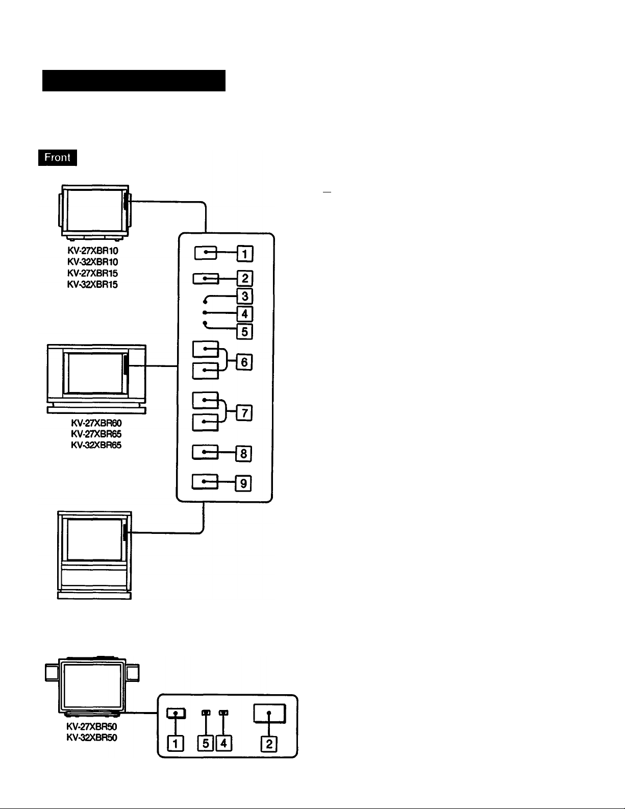
Location of Controls
Refer to the pages indicated in • for detaiis.
iT) Remote control detector
[UpOWER swHch •
(DsLEEP indicator •
QsTEREO indicator •
(DtIMER indicator #
[ejCHANNEL scan buttcns •
(HVOLUME buttons •
(HtV/VIDEO button •
(Doniy for KV-27XBR10/32XBR10/27XBR60/32XBR70
SRS (Sound Retrieval System) button #
Only for KV-27XBR15/32XBR15/27XBR65/32XBR66
MULTI PICTURE button #
KV-32XBR70
KV-27XBR50/32XBR50 have only the POWER
switch on the TV.
V
© © ©
©
©
©
© © ©
1 won
vrao
L
<ai^
AUtn
R
IBlIQFroi
e
©
©
©
ra
!»»□
©
©
0 0
|io)AUX (auxiliary terminal i
QljvIDEO 1, 2, 3 IN Jacks i
OUlUIONITOR OUT jacks •
(iHsPEAKER SW (swRch) i
Only for KV 27XBR1S/32XBR15 Only for KV-27XBRS0/32XBR50
16
IhItO converter terminal •
QsjVHFAJHF antenna terminal #
liilAUDIO OUT (VARIABLE jacks O
The whitened parts are only for KV-32XBR15,
KV-27XBR15. KV-32XBR50 and KV-27XBR50.
See below.
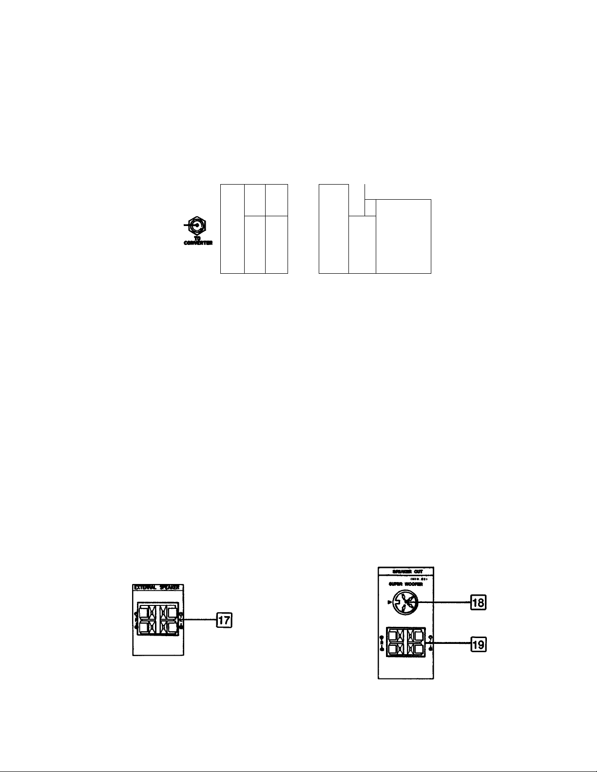
|i7| EXTERNAL SPEAKER terminals i QDsUPER woofer jack •
lie) SPEAKER OUT terminals (for main speakers) i
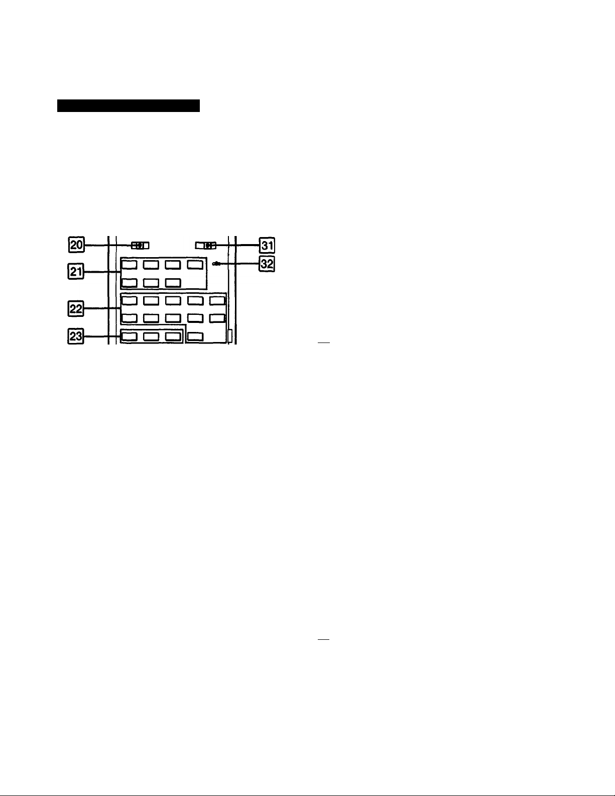
Programmable Commander
Refer to the pages indicated in • for details.
Pag □
a a CH
□ □□ m3
c£b
mi mj mi
mi
db
28
o □
m-
SP
I^Only for KV-27XBR15/32XBR15/27XBR65/32XBR65
PIP/VIDEOfCABLE selector # #
Only for KV-27XBR10/32XBR10/27XBRS0/32XBR50/
27XBR60/32XBR70
VIDEO/CABLE selector •
HHaV window buttons •
miOnly for KV-27XBR15/32XBR15/27XBR65/32XBR65
Buttons for pfoture'lnplcturs and Sony video
equipment # 9
Only for KV-27XBR10/32XBR10/27XBRS0f32XBRS0f
27XBR60/32XBR70
Buttons used for Sony video equipment #
(^Channel presetting buttons • #
Hfl MUTING button •
|2S|Input select buttons*
(TV, VIDEO 1, VIDEO 2, VIDEO 3) •
1^ Channel number buttons #
IzIdISPLAY button •
IHeNTER button •
HItiME button •
(^PICTURE buttons •
HilVTR 1f2/3/MDP selector •
□
HIleaRN indicator •
mSLEEP button •
I^POWER button* •
HHCABLE button •
I^ANT/AUX button •
HBOnly for KV-27XBR50/32XBR50
WOOFER button •
I^Only for KV-27XBR50/32XBR50
ASC button O
|39|SRS ^ound Retrieval System) button* #
I^MTS (Multichannel TV SouikI) button #
■fl
|4i|jUMP button •
@CH (channeO scan buttons* #
@VOL (volunte) buttons* #
EIuSOLEARN selector#
«These buttons are also on the TV.
(Models equipped with picture-in-picture function do not
have an SRS button on the TV).
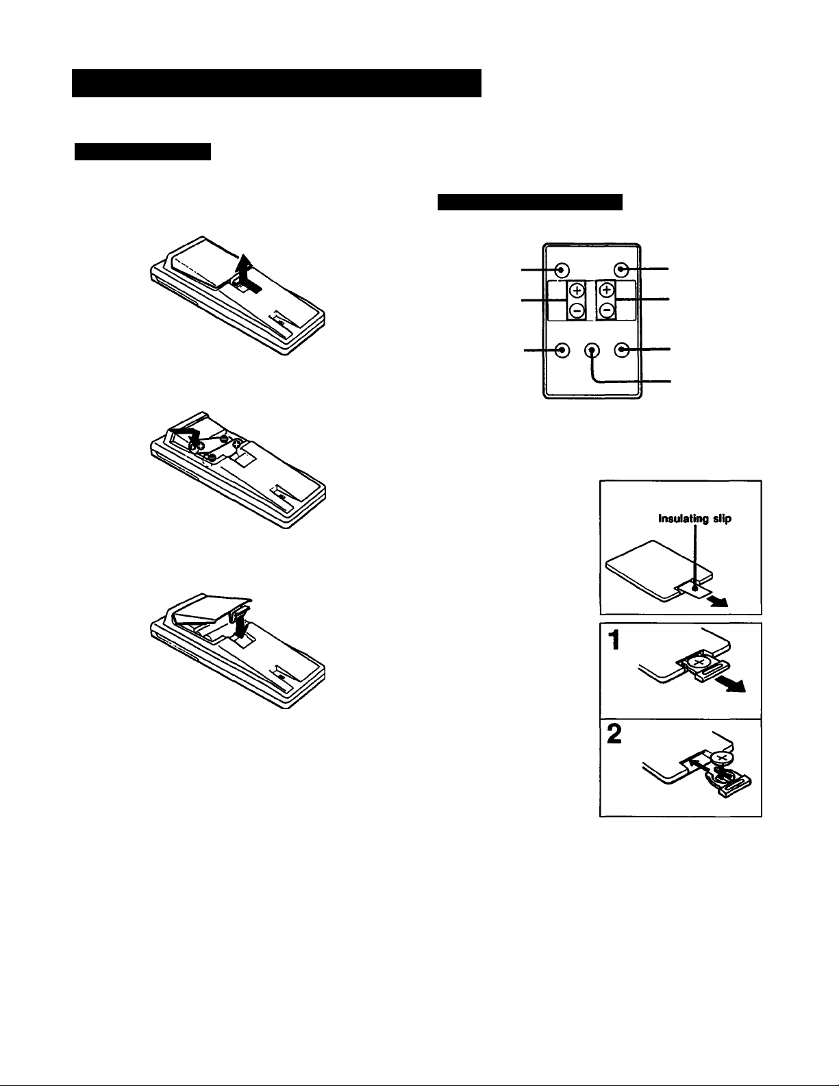
Preparing the Remote Commander
Battery Installation
Push to open the iid.
1
instaii two size AA (RQ batteries with the
correct poiarity.
2
Repiace the iid.
3
The Mini Commander is suppiied oniy for KV-27XBR50
and KV-32XBR50.
Mini Commander RM-K1T
MUTING button
VOLUME +/
buttons
DISPLAY button
This Mini Commander has the minimum function buttons
for watching the TV.
Before use
The initial battery is
installed at the factory.
Remove the transparent
Insulating slip before
operation.
POWER button
CHANNEL +/buttons
SLEEP button
TV/VIDEO button
In normal operation, batteries will last up to half a year.
If the unit does not operate properly, the batteries might be
exhausted. Repiace ail of them with new ones.
To avoid damage from possible battery leakage, remove the
batteries when the Remote Commander will not be used for
a long time.
How to replace the battery
1 Pull out the battery case.
2 Insert a Sony CR202S
battery with the flat
surface (positive side)
upward.
Use of a battery other than
the Sony CR202S lithium
battery may create a risk of
fire or explosion.
Notes on the lithium battery
• Keep the lithium battery out of the reach of children.
Should the battery be swallowed, immediately consult a
doctor.
• Be sure to observe the correct polarity when installing the
battery.
• Do not hold the battery with metallic tweezers, otherwise a
short-circuit may occur.
• Replace the battery with a Sony CR2025 lithium battery. Use
of another battery may present a risk of fire or explosion.
WARNING
Battery may explode if mistreated. Do not recharge,
disassemble or dispose of it in fire.
Connecting the TV Antenna/Cable
Either an indoor antenna or outdoor antenna can be
connected. For better quaiity picture, connecting an
outdoor antenna is recommended.
Cable TV reception is only possible by connecting a
cable supplied by your local cable company.
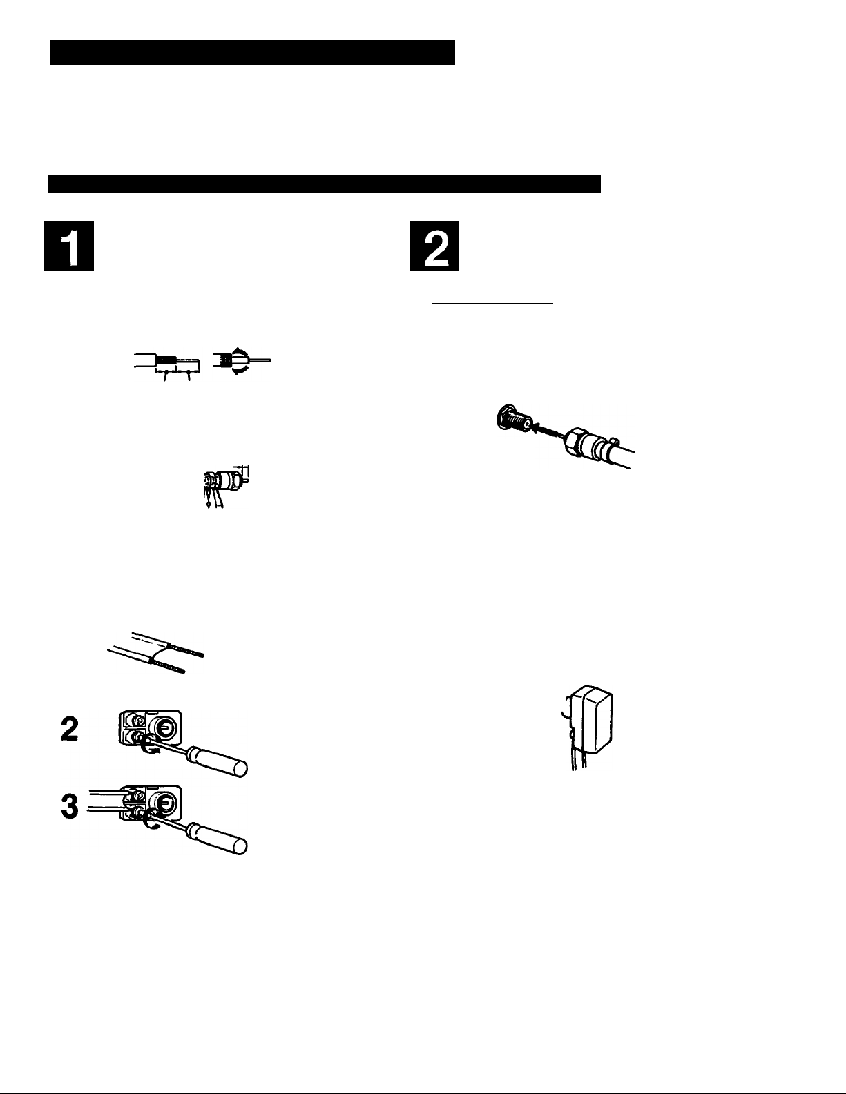
To Connect a VHF, UHF, or VHF/UHF Combination Antenna* or CATV Cable
Check the cable type and prepare the cable
end using the appropriate connector.
7&ohm coaxial cable (round)
Attach an optional Ftype oonnector.
Plug the connector Into VHFAJHF on the
rear of the TV.
75-ohm coaxial cable ^nd)
1
7 mm (’/4 Inch) 10 mm (®/8 inch)
F-type connector
2
3 mm (’/8 inch)
VHF/UHF
3
4
SOO-ohm twinlead cable
Attach the supplied antenna connector.
1
Loosen with a
screwdriver.
Attach the
cable and
fasten with a
screwdriver.
» Most combination antennas are equipped with a signal
splitter. Remove the splitter and attach the appropriate
connector.
300-ohm twin-lead cable (flat)
VHF/UHF
For a better quality picture, it is recommended to use the
optional cable so that the 300 ohm twin-lead cable can be
kept at a distance from the TV set.
10
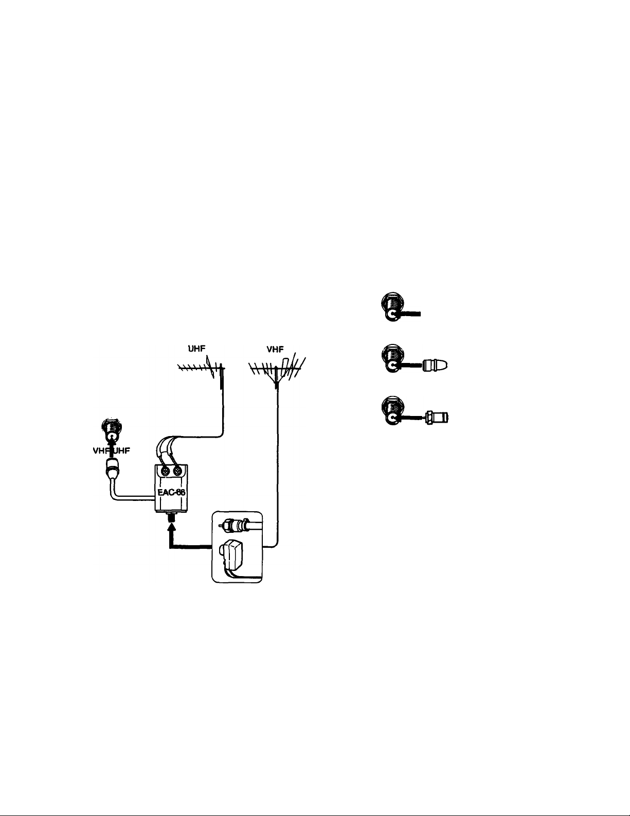
When you connect both VHP and UHF antennas
When you connect a cable with a special
converter/deccder* for pay cable TV systems
Use the optional EAC66 U/V mixer.
1 Prepare the VHP antenna end using the
appropriate connector.
2 Connect the cables to the mixer.
3 Plug the mixer to VHP/UHP.
Pay cable TV systems use scrambled or encoded
signals and require special converters (decoders) in
addition to the normal cable connection.
H|CD=
AUX
<3D^
TO
CONVERTER
VHF/UHF
When you connect both VHP/UHP antennas and a
CATV cable
Optional 75-ohm
coaxial cable
Converter/
decoder
CATV
cable
When the U/V mixer is used
Snow and noise may appear in the pictures of the cable TV
channels over 37 (W-f 1).
«The special converter/decoder will be supplied by the cable
company.
AUX
TO
TO
>NVEF
CONVERTER
VHF/UHF
Note
In this case, do not connect anything to the TO
CONVERTER terminal.
CATV
cable
VHF/UHF
antenna cable
Installing the Speakers
The main speakers and the super woofer are supplied only for KV-27XBR50 and KV-32XBR50.
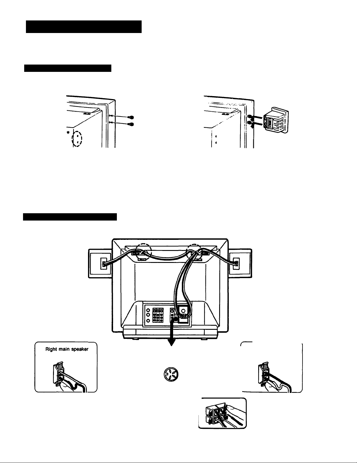
Installing the Main Speakers
Fasten the supplied screws.
1
«The main speakers can be attached deep at the rear portion
of the TV, too.
Connecting the Main Speakers
Make sure to turn off the TV before connecting №e speaker cords.
Install the main speakers left and right.
2
The main speakers can be placed anywhere within the reach
of the speaker cords instead of attaching them to the TV.
When installing them on the TV. be sure not to place them on
the woofer. The speakers are provided with camera screws for
installation on a speaker stand, tripod, etc.
Connect the black«
cord as illustrated.
Connect the red —-
cord as illustrated.
12
Right speaker
Rear of the TV
■WWI OUT
iniiii
Left main speaker
Left speaker
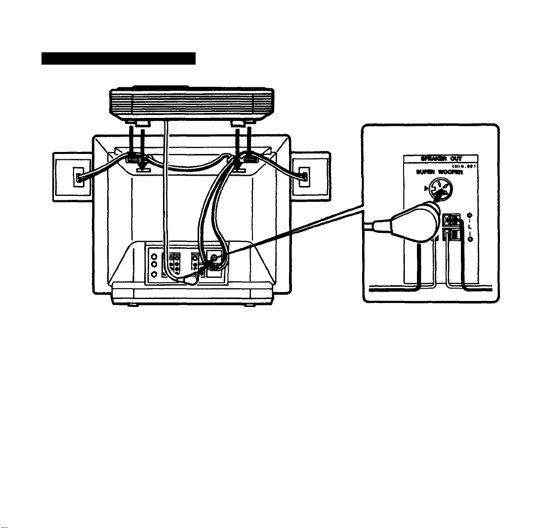
Connecting the Super Woofer
1 Insert the projecting parts at the bottom of the super
woofer into the receptacles on the top of the TV.
2 Connect the super woofer cord to the SUPER
WOOFER Jack on the rear of the TV.
The super woofer is factory^t at the powerful sound.
Press WOOFER on the Remote Commander to make
bass sound less emphasized.
Notes on the speakers
• Do not carry the TV holding the main speakers.
• The low bass sound is output from the super woofer. Be
careful not to block the openings of the super woofer when
installing the TV. Othenwise, the low bass sound will not be
fully reproduced.
• Be sure to use the supplied speakers, since the TV and the
soeakers oroduce sounds as one unit.
With this connection, you wiii be abie to...
—View the playback of video tapes
—Record TV programs
—Record a TV program while viewing another
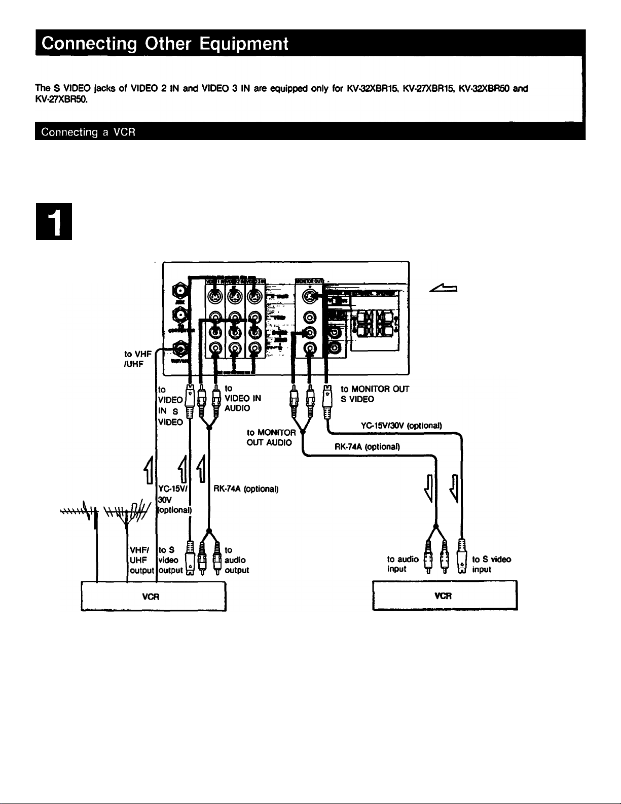
Connecting VCRs with an S video output jack
Iñearof TV
: Signal flow
KV-32XBR15/27XBR15
Notes: The signal input to VIDEO IN cannot be output from S VIDEO OITT.
The signal input to S VIDEO IN can only be output from S VIDEO OUT.
"Roles
• If you connect a monaural VCR, connect the audio output of
the VCR to the L (MONO) jack of VIDEO 1/2/3 IN of the TV.
The monaural sound will be heard from both speakers.
• For operation, refer to the instruction manual furnished with
the VCR.
• The signals input from VIDEO 1/2/3 IN are not output from
MONITOR OUT.
• Keep the VCR away from the TV if the picture or sound is
affected.
M
About S video input
Video input and output signals can be separated into Y
(luminance or brightness) and C (chroma or color) signals.
Usually these two signals are combined in a VCR and sent as
one signal to a TV. Separation of the Y and C signals
prevents them from interfering with one another, thereby
improving picture (especially in coloi) quality.
This unit is equipped with an S video input jack through
which these separated signals can be input directly.
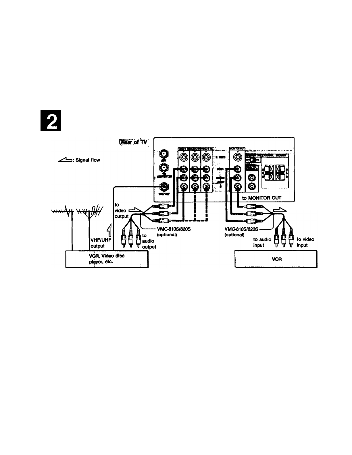
Connecting VCRs/video (fisc players not equipped with an S video output jack
KV-32XBR15/27XBR15
Preparations
Turn on the TV.
Press the TVA^IDEO button on the TV or an input
select button on the Remote Commander so that
the “VIDEO 1”, “VIDEO 2" or “VIDEO 3”
Indication appears on the screen.
VIDEO 1: for equipment connected to VIDEO 1 IN
VIDEO 2: for equipment connected to VIDEO 2 IN
VIDEO 3: for equipment connected to VIDEO 3 IN
You can label each of these input modes. For
details, see page 40.
To view one TV program while recording another
Press the TV/VTR mode select button on the VCR or Remote
(k>mmander so that the VCR will be in the TV mode. Press
the TV button on the Remote Commander, and select the
channel you want to view.
Operation
For operation, refer to the instruction manual furnished
with the VCR.
When using an infrared remote control VCR made by
Sony or other manufacturer, the VCR can be operated
with the supplied Remote Commander.
See “Using the Programmable Remote Commander”
on page 44.
To return to the TV nwde
—Press the TV/VIDEO button on the TV so that a
channel number appears on the screen.
—Press the TV button on the Remote Commander.
When you cannot obtain a clear picture and/or sound
Make sure that the TV/VTR mode select button on the VCR is
set to TV. Re-select the desired channel with the buttons on
the TV or the Remote Commander.
15
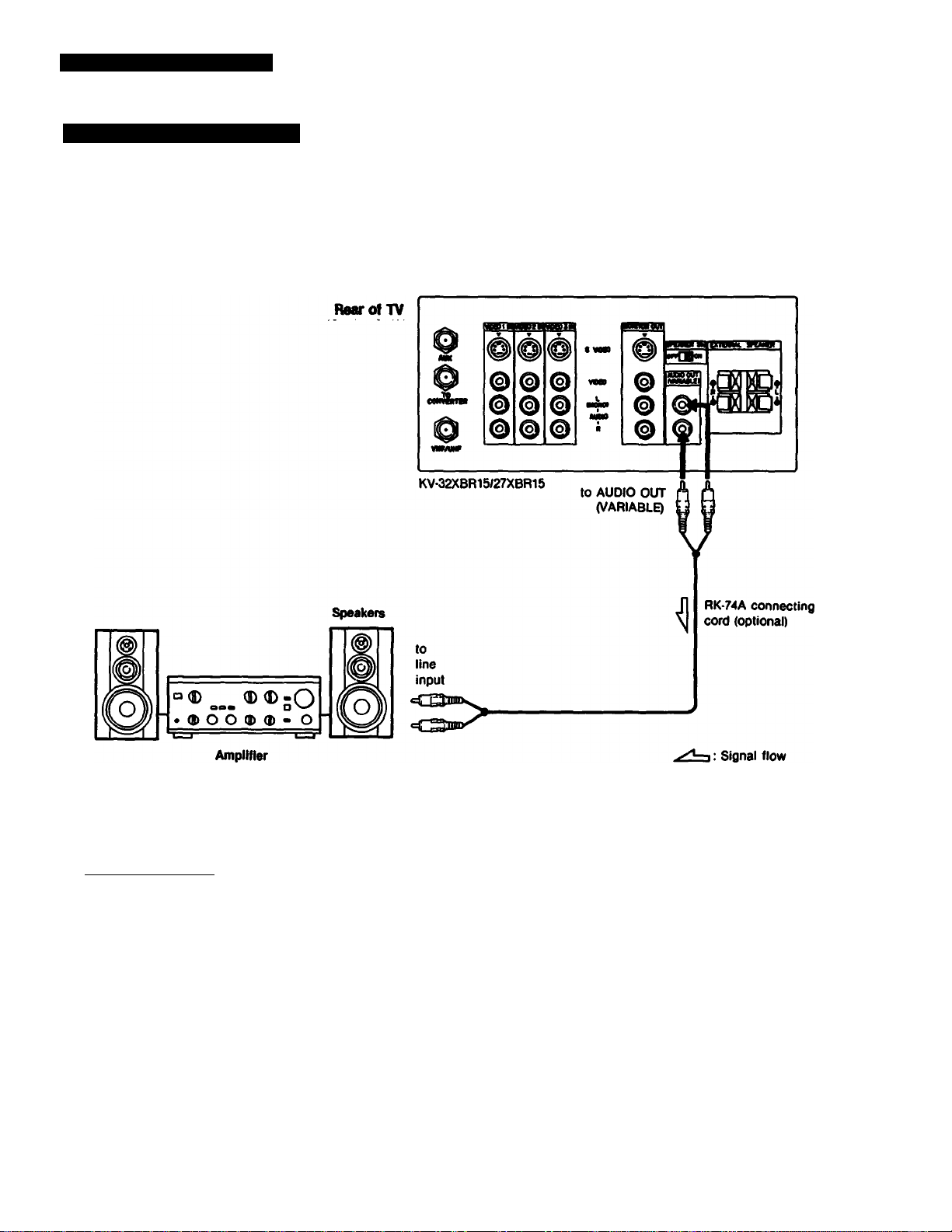
Connecting Other Equipment
Connecting an Audio System
—To listen to the TV or connected VCR sound through an audio system
Set the amplifier’s function
to line input.
To adjust the sound level
Leave the amplifier volume, bass and treble
controls at their mid position and adjust the level
with the VOLUME buttons on the TV or the VOL
buttons on the Remote Commander.
When an audio system is connected to AUDIO OUT, be sure
to set the SPEAKER SW (switch) on the TV to OFF.
The sound from the TV’s speakers will be cut off.
16
For better sound, we recommend that you use the optional
video rack (see page 50).
 Loading...