

SONY KV-21FS140 Service Manual

HISTORY INFORMATION FOR THE FOLLOWING MANUAL:
SERVICE MANUAL
MODEL NAME REMOTE COMMANDER DESTINATION CHASSIS NO.
KV-21FS140
KV-21FS140
RM-YA005 LATIN NORTH SCC-S79A-A
RM-YA005 LATIN SOUTH SCC-S79B-A
BX-1S
CHASSIS
ORIGINAL MANUAL ISSUE DATE: 2/2006
REVISION DATE SUBJECT
2/2006 No revisions or updates are applicable at this time.
TRINITRON® COLOR TELEVISION
9-965-997-01
Self Diagnosis
Supported model
SERVICE MANUAL
MODEL NAME REMOTE COMMANDER DESTINATION CHASSIS NO.
KV-21FS140
KV-21FS140
RM-YA005 LATIN NORTH SCC-S79A-A
RM-YA005 LATIN SOUTH SCC-S79B-A
BX-1S
CHASSIS
9-965-997-01
KV-21FS140 RM-YA005
TRINITRON® COLOR TELEVISION

KV-21FS140
TABLE OF CONTENTS
SECTION TITLE PAGE SECTION TITLE PAGE
Specifi cations ........................................................................... 4
Warnings and Cautions ............................................................ 5
Safety Check-Out ..................................................................... 6
Self-Diagnostic Function .......................................................... 7
SECTION 1: DISASSEMBLY ................................................................. 9
1-1. Rear Cover Removal ........................................................ 9
1-2. Chassis Assembly Removal ............................................. 9
1-3. Service Position .............................................................. 10
1-4. Picture Tube Removal .....................................................11
Anode Cap Removal Procedure ......................................11
SECTION 2: SET-UP ADJUSTMENTS ................................................ 12
2-1. Beam Landing ................................................................ 12
2-2. Convergence .................................................................. 13
2-3. Focus .............................................................................. 14
2-4. Screen (G2) .................................................................... 15
SECTION 3: CIRCUIT ADJUSTMENTS .............................................. 16
3-1. Remote Adjustment Buttons and Indicators ................... 16
3-2. Accessing the Service Menu Mode ................................ 17
3-3. Confi rming Service Adjustment Changes ....................... 18
3-4. White Balance Adjustments ............................................ 18
3-5. Picture Quality Adjustments ........................................... 18
PAL 50Hz Normal Mode ......................................................... 19
SECTION 4: DIAGRAMS ..................................................................... 35
4-1. Circuit Boards Location .................................................. 35
4-2. Printed Wiring Board and
Schematic Diagram Information ..................................... 35
4-3. Block Diagrams and Schematics .................................... 36
Signal Flow Block Diagram ............................................ 36
4-4. Schematics and Supporting Information ........................ 37
A Board Schematic Diagram (1 of 6) ............................. 37
A Board Schematic Diagram (2 of 6) ............................. 38
A Board Schematic Diagram (3 of 6) ............................. 39
A Board Schematic Diagram (4 of 6) ............................. 40
A Board Schematic Diagram (5 of 6) ............................. 41
A Board Schematic Diagram (6 of 6) ............................. 42
C Board Schematic Diagram ......................................... 44
4-5. Semiconductors .............................................................. 46
SECTION 5: EXPLODED VIEWS ........................................................ 47
5-1. Chassis ........................................................................... 47
5-2. Picture Tube ................................................................... 48
SECTION 6: ELECTRICAL PARTS LIST ............................................ 49
KV-21FS140
3
SPECIFICATIONS
!
+)*!
6)*/7/6!
.'
"#
'()*
,).'/!
'3).'/!
#
$
%
!
!
&!
!
5!
(8
9
1)
1 Vp-p 75 ohms unbalanced, sync negative
2) Y: 1.0 Vp-p, 75 ohms, sync negative; PB: 0.7 Vp-p, 75 ohms;
PR Vp-p, 75 ohms.
3)
500 mVrms (100% modulation), Impedance: 47 kilohms
4)
This specifi cation is the maximum wattage.
KV-21FS140
Television system
American TV standard, NTSC
Channel coverage
VHF: 2-13/UHF: 14-69/CATV: 1-125
Antenna
75-ohm external antenna terminal for VHF/UHF
Picture tube
FD Trinitron® tube
Visible screen size
20-inch picture measured diagonally
Actual screen size
21-inch measured diagonally
Supplied Accessories
Remote Commander RM-YA005
Two Size AA (R6) Batteries
Optional Accessories
Cables: VMC-810S/820S, VMC-720M,
YC-YC-15V/30V, RK74A
As an ENERGY STAR® Partner, Sony
Corporation has determined that this
product meets the ENERGY STAR®
guidelines for energy efficiency. ENERGY
STAR® is a U.S. registered mark.
SRS and the ( )® symbol are trademarks of
SRS Labs, Inc.
Manufactured under license from Dolby
Laboratories Licensing Corporation. Dolby
and the double-D symbol are trademarks of
Dolby Laboratories.
Manufactured under license from BBE Sound,
Inc. Licensed by BBE Sound, Inc. under USP
4638258, 5510752 and 5736897. BBE and BBE
symbol are registered trademarks of BBE
Sound, Inc.
WEGA, FD Trinitron and Steady Sound are registered
trademarks of Sony Corporation.
Design and specifi cations are subject to change without notice.
KV-21FS140
4

KV-21FS140
WARNINGS AND CAUTIONS
CAUTION
Short circuit the anode of the picture tube and the anode cap to the metal chassis, CRT shield, or carbon painted on the CRT, after
removing the anode.
WARNING!!
An isolation transformer should be used during any service to avoid possible shock hazard, because of live chassis. The chassis of this
receiver is directly connected to the AC power line.
! SAFETY-RELATED COMPONENT WARNING!!
Components identifi ed by shading and ! mark on the schematic diagrams, exploded views, and in the parts list are critical for safe
operation. Replace these components with Sony parts whose part numbers appear as shown in this manual or in supplements published
by Sony. Circuit adjustments that are critical for safe operation are identifi ed in this manual. Follow these procedures whenever critical
components are replaced or improper operation is suspected.
KV-21FS140
5
SAFETY CHECK-OUT
KV-21FS140
After correcting the original service problem, perform the following
safety checks before releasing the set to the customer:
1. Check the area of your repair for unsoldered or poorly soldered
connections. Check the entire board surface for solder splashes and
bridges.
2. Check the interboard wiring to ensure that no wires are “pinched” or
touching high-wattage resistors.
3. Check that all control knobs, shields, covers, ground straps, and
mounting hardware have been replaced. Be absolutely certain that
you have replaced all the insulators.
4. Look for unauthorized replacement parts, particularly transistors,
that were installed during a previous repair. Point them out to the
customer and recommend their replacement.
5. Look for parts which, though functioning, show obvious signs of
deterioration. Point them out to the customer and recommend their
replacement.
6. Check the line cords for cracks and abrasion. Recommend the
replacement of any such line cord to the customer.
7. Check the B+ and HV to see if they are specifi ed values. Make sure
your instruments are accurate; be suspicious of your HV meter if
sets always have low HV.
8. Check the antenna terminals, metal trim, “metallized” knobs,
screws, and all other exposed metal parts for AC leakage. Check
leakage as described below.
Leakage Test
The AC leakage from any exposed metal part to earth ground and from
all exposed metal parts to any exposed metal part having a return to
chassis, must not exceed 0.5 mA (500 microamperes). Leakage current
can be measured by any one of three methods.
1. A commercial leakage tester, such as the Simpson 229 or RCA
WT-540A. Follow the manufacturers’ instructions to use these
instructions.
2. A battery-operated AC milliampmeter. The Data Precision 245
digital multimeter is suitable for this job.
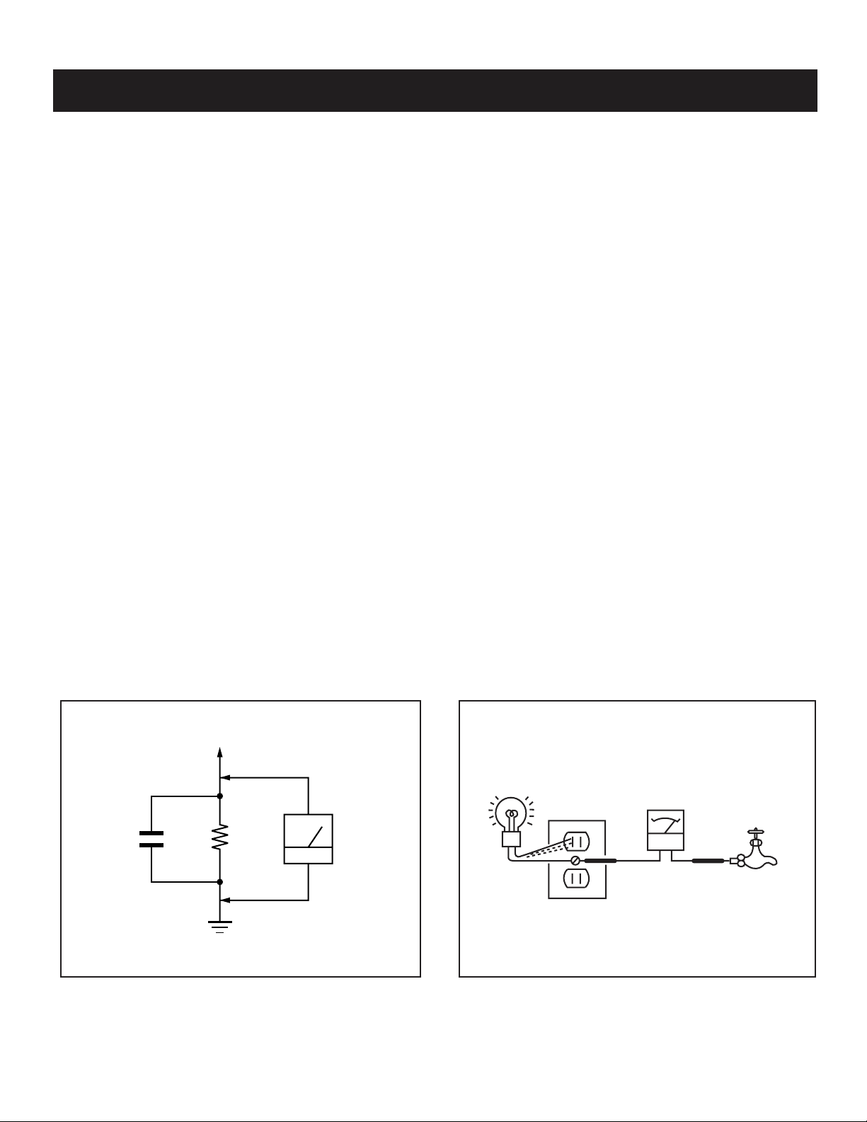
3. Measuring the voltage drop across a resistor by means of a VOM
or battery-operated AC voltmeter. The “limit” indication is 0.75 V,
so analog meters must have an accurate low voltage scale. The
Simpson’s 250 and Sanwa SH-63TRD are examples of passive
VOMs that are suitable. Nearly all battery-operated digital
multimeters that have a 2 VAC range are suitable (see Figure A).
How to Find a Good Earth Ground
A cold-water pipe is a guaranteed earth ground; the cover-plate
retaining screw on most AC outlet boxes is also at earth ground. If the
retaining screw is to be used as your earth ground, verify that it is at
ground by measuring the resistance between it and a cold-water pipe
with an ohmmeter. The reading should be zero ohms.
If a cold-water pipe is not accessible, connect a 60- to 100-watt troublelight (not a neon lamp) between the hot side of the receptacle and the
retaining screw. Try both slots, if necessary, to locate the hot side on
the line; the lamp should light at normal brilliance if the screw is at
ground potential (see Figure B).
0.15 µF
Figure A. Using an AC voltmeter to check AC leakage. Figure B. Checking for earth ground.
KV-21FS140
To Exposed Metal
Parts on Set
1.5 K Ω
Earth Ground
AC
Voltmeter
(0.75 V)
Trouble Light
AC Outlet Box
Ohmmeter
Cold-water Pipe
6
KV-21FS140
SELF-DIAGNOSTIC FUNCTION
Self Diagnosis
Supported model
The units in this manual contain a self-diagnostic function. If an error occurs, the STANDBY LED indicator will automatically begin to fl ash. The number of
times the LED fl ashes translates to a probable source of the problem. A defi nition of the STANDBY LED fl ash indicators is listed in the instruction manual
for the user’s knowledge and reference. If an error symptom cannot be reproduced, the Remote Commander can be used to review the failure occurrence
data stored in memory to reveal past problems and how often these problems occur.
1. Diagnostic Test Indicators
When an error occurs, the STANDBY LED indicator will fl ash a set number of times to indicate the possible cause of the problem. If there is more than
one error, the indicator will identify the fi rst of the problem areas.
Results for all of the following diagnostic items are displayed on screen. No error has occurred if the screen displays a “0”.
Diagnostic Item
Description
Power does not turn on
+B overcurrent (OCP)*
V-Protect (OVP)
IK (AKB)
Power Supply
NG (+5V) for
Video Processor
No. of Times
STANDBY LED
Indicator Flashes
Does not light
2 times *
4 times
5 times
8 times
Self-Diagnositc
Display/
Diagnostic Result
2:0
or
2:1 - 255
4:0
or
4:1 - 255
5:0
or
5:1 - 255
8:0
or
8:1 - 255
Probable Cause Location
• Power cord is not plugged in.
• Fuse is burned out (F600). (A Board)
• H.OUT (Q805) is shorted. (A Board)
• IC751 is shorted. (C Board)
• +13V is not supplied. (A Board)
• IC804 is faulty. (A Board)
• Video OUT (IC1545) is faulty(A Board)
• IC001 is faulty. (A Board)
• Screen (G2) is improperly adjusted.**
• IC604 is faulty.
• IC602 is faulty.
Detected Symptoms
• Power does not come on.
• No power is supplied to the TV.
• AC Power supply is faulty.
• Power does not come on.
• Load on power line is shorted.
• Has entered standby state after horizontal raster.
• Vertical defl ection pulse is stopped.
• Power line is shorted or power supply is stopped.
• No raster is generated.
• CRT Cathode current detection reference pulse
output is small.
• No power supply to CRT Anode.
• No RASTER is generated.
*One fl ash count is not used for self-diagnostic.
*If a +B overcurrent is detected, stoppage of the vertical defl ection is detected simultaneously. The symptom that is diagnosed fi rst by the mircrocontroller
is displayed on the screen.
**Refer to Screen (G2) Adjustments in Section 2-4. of this manual.
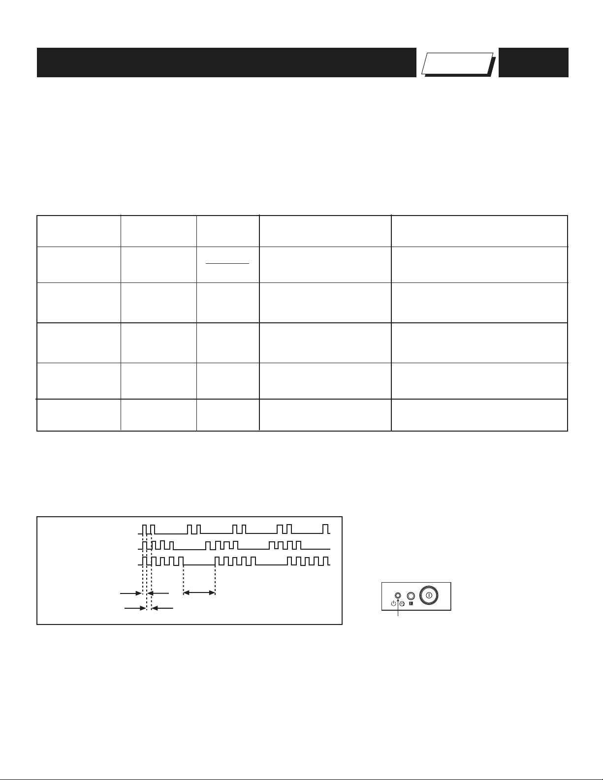
2. Display of STANDBY LED Flash Count
2 times
4 times
5 times
LED ON 0.3 sec.
LED OFF 0.3 sec.
LED OFF
3 sec.
Standby indicator
3. Stopping the STANDBY LED Indicator Flash
Turn off the power switch on the TV main unit or unplug the power cord from the outlet to stop the STANDBY LED Indicator from fl ashing.
4. Self-Diagnostic Screen Display
For errors with symptoms such as “power sometimes shuts off” or “screen sometimes goes out” that cannot be confi rmed, it is possible to bring up past
occurrences of failure on the screen for confi rmation.
KV-21FS140
7
To Bring Up Screen Test
In standby mode, press buttons on the Remote Commander sequentially, in rapid succession, as shown below:
KV-21FS140
The following screen will be displayed indicating the error count:
Handling of Self-Diagnostic Screen Display
Since the diagnostic results displayed on the screen are not automatically cleared, always check the self-diagnostic screen during repairs. When you
have completed the repairs, clear the result display to “0”.
Unless the result display is cleared to “0”, the self-diagnostic function will not be able to detect subsequent faults after completion of the repairs.
Clearing the Result Display
To clear the result display to “0”, press buttons on the Remote Commander sequentially when the diagnostic screen is displayed, as shown below:
DISPLAY
SELF DIAGNOSTIC
2 OCP : 0
3 OVP : N/A
4 VSTOP : 0
5 AKB : 1
8 SUP : 0
101 WDT : N/A
SERIAL:
MODEL:
Channel
5
Sound Volume -
Number “0” means that no fault was detected.
Number “1” means a fault was detected one time only.
POWER
Note that this differs from entering the Service Mode (Sound Volume + ).
Channel 8
Quitting the Self-Diagnostic Screen
To quit the entire self-diagnostic screen, turn off the power switch on the Remote Commander or the main unit.
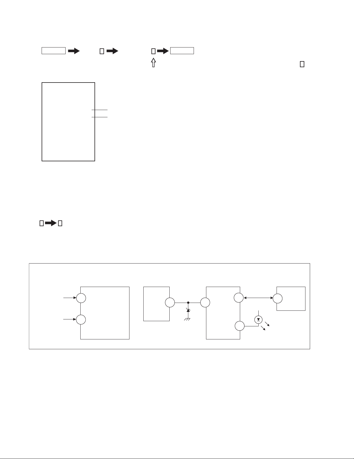
Self-Diagnostic Circuit
FROM
C BOARD
IC751 PIN 5
0
A BOARD
IC001
Y/CHROMA JUNGLE
84
IK
A BOARD
IC804
V. OUT
F.B-PLS
3
A BOARD
IC001
SYSTEM
13
V. GUARD
SDAO
109
A BOARD
IC003
MEMORY
5
SDA
FROM
32
A BOARD
Q816
COLLECTOR
+B overcurrent (OCP)
Occurs when an overcurrent on the +B (135V) line is detected by pin 32 of IC001 (A Board). If the voltage of pin 32 of IC001 (A Board) is more than 4V
when V.SYNC is more than seven verticals in a period, the unit will automatically turn off.
V-Protect
Occurs when an absence of the vertical defl ection pulse is detected by pin 13 of IC001 (A Board). Power supply will shut down when waveform interval
exceeds 2 seconds.
IK (AKB)
If the RGB levels* do not balance within 15 seconds after the power is turned on, this error will be detected by IC001 (A Board). TV will stay on, but there
will be no picture.
Power Supply NG (+5V) for Video Processor
Occurs when IC001 internal HV protect detects an abnormal H-Pulse (frequency) due to improper power supply to IC001. The TV cuts off high voltage
power of anode CRT. No picture will be detected. eg: faulty IC602 or IC604
EHTO
RED-LED
122
DISPLAY
KV-21FS140
8
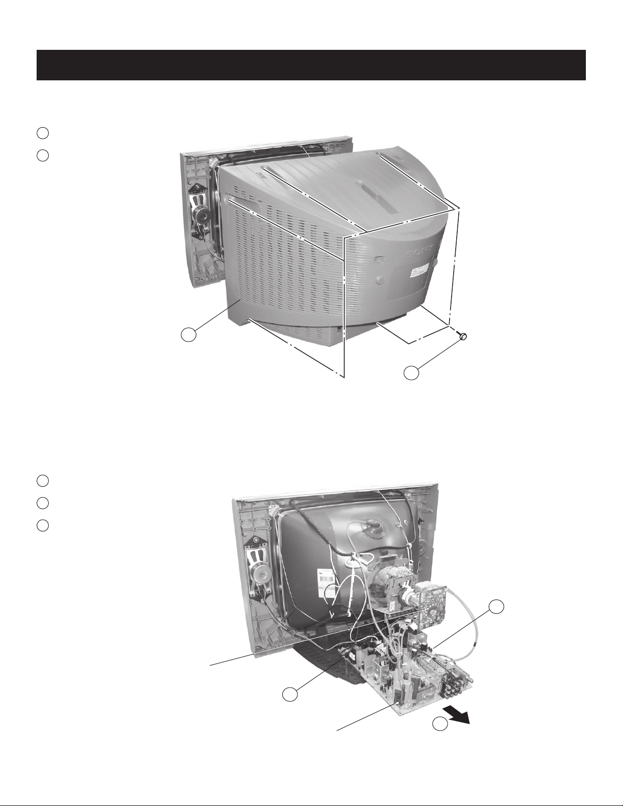
1-1. REAR COVER REMOVAL
1
Remove 7 screws
+BVTP 4X16
2
Remove rear cover
KV-21FS140
SECTION 1: DISASSEMBLY
2
1-2. CHASSIS ASSEMBLY REMOVAL
1
Release power cord.
2
Press on catch tab to release A Board.
3
Gently pull the chassis forward.
1
1
KV-21FS140
C Board
2
A Board
3
Chassis Assembly
9
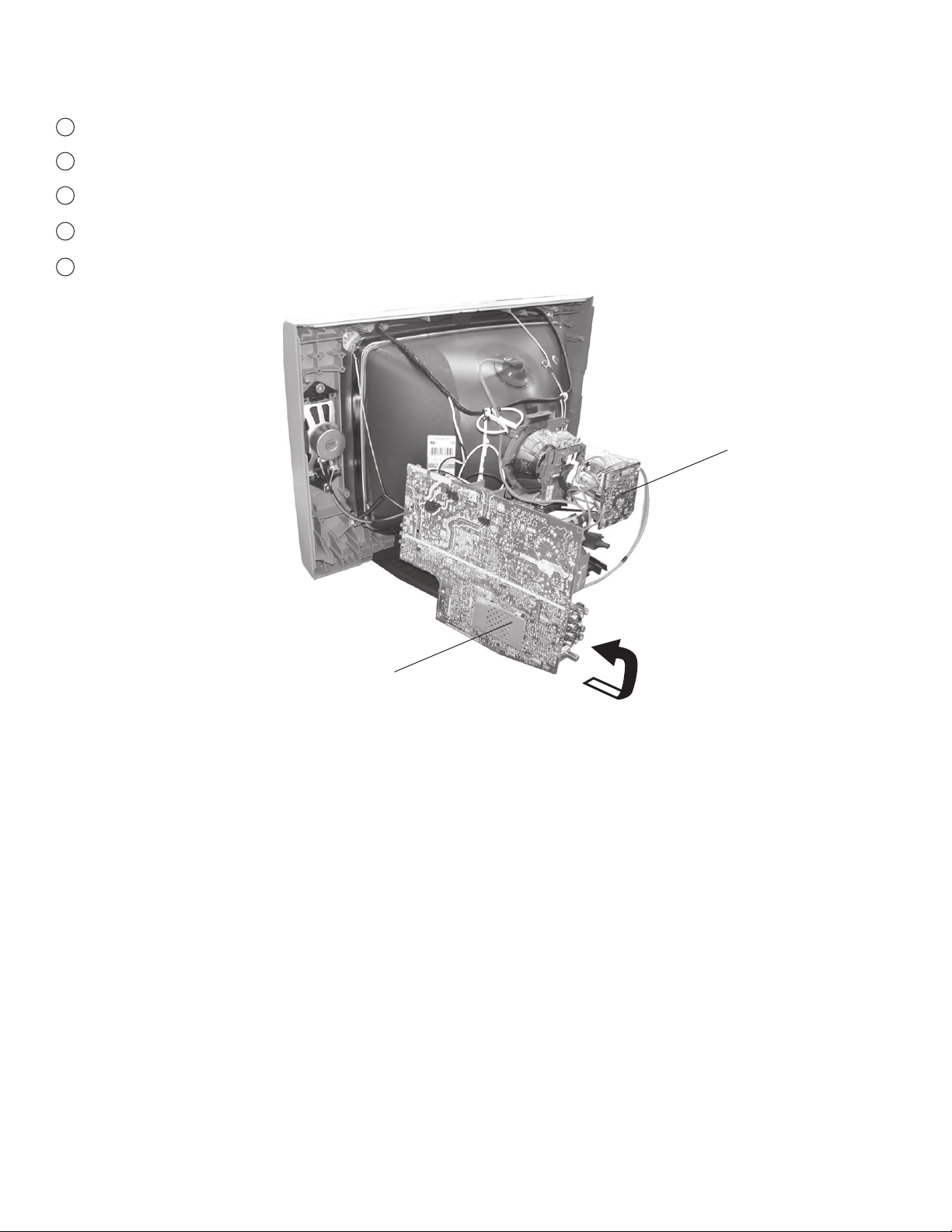
1-3. SERVICE POSITION
1
Press on catch tab to release A Board.
2
Gently pull the A Board forward to access the CN200 connector (to speakers)
3
Disconnect the CN200 from the A Board.
Gently continuing pulling the A Board and rotate into service position.
4
Reconnect CN200.
5
KV-21FS140
C Board
A Board
KV-21FS140
10
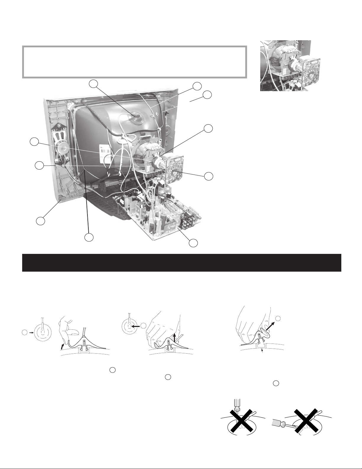
1-4. PICTURE TUBE REMOVAL
WARNING: BEFORE REMOVING THE ANODE CAP
High voltage remains in the CRT even after the power is disconnected. To avoid electric shock,
discharge CRT before attempting to remove the anode cap. Short between anode and CRT
coated earth ground strap.
KV-21FS140
1
2
6
10
9
7
8
1. Discharge the anode of the CRT and remove
the anode cap.
5
3
4
2. Unplug all interconnecting leads from the
defl ection yoke, neck assembly, degaussing
coils and CRT grounding strap.
3. Remove the C Board from the CRT.
4. Remove the chassis assembly.
5. Loosen the neck assembly fi xing screw and
remove.
6. Loosen the defl ection yoke fi xing screw and
remove.
7. Place the set with the CRT face down on
a cushion and remove the degaussing coil
holders.
8. Remove the degaussing coils.
9. Remove the CRT grounding strap and spring
tension devices.
10. Unscrew the four CRT fi xing screws [located on
each CRT corner] and remove the CRT [Take
care not to handle the CRT by the neck].
ANODE CAP REMOVAL PROCEDURE
WARNING: High voltage remains in the CRT even after the power is disconnected. To avoid electric shock, discharge CRT before attempting to remove
the anode cap. Short between anode and coated earth ground strap of CRT.
NOTE: After removing the anode cap, short circuit the anode of the picture tube and the anode cap to either the metal chassis, CRT shield, or carbon
painted on the CRT.
REMOVAL PROCEDURES
c
b
a
Anode Button
Turn up one side of the rubber cap in
the direction indicated by arrow a .
HOW TO HANDLE AN ANODE CAP
1. Do not use sharp objects which may cause damage to the surface of the
anode cap.
2. To avoid damaging the anode cap, do not squeeze the rubber covering too
hard. A material fi tting called a shatter-hook terminal is built into the rubber.
3. Do not force turn the foot of the rubber cover. This may cause the shatterhook terminal to protrude and damage the rubber.
Use your thumb to pull the rubber
cap fi rmly in the direction indicated
by arrow b .
When one side of the rubber cap separates from
the anode button, the anode cap can be removed
by turning the rubber cap and pulling it in the
direction of arrow c .
KV-21FS140
11
SECTION 2: SET-UP ADJUSTMENTS
KV-21FS140
The following adjustments should be made when a complete realignment
is required or a new picture tube is installed.
These adjustments should be performed with rated power supply voltage
unless otherwise noted.
Set the controls as follows unless otherwise noted:
Picture control NORMAL
Brightness control NORMAL
2-1. BEAM LANDING
Before beginning adjustment procedure:
1. Feed in the white pattern signal.
2. In order to reduce the geomagnetism on the set’s picture tube, face
it east or west.
Adjustment Procedure
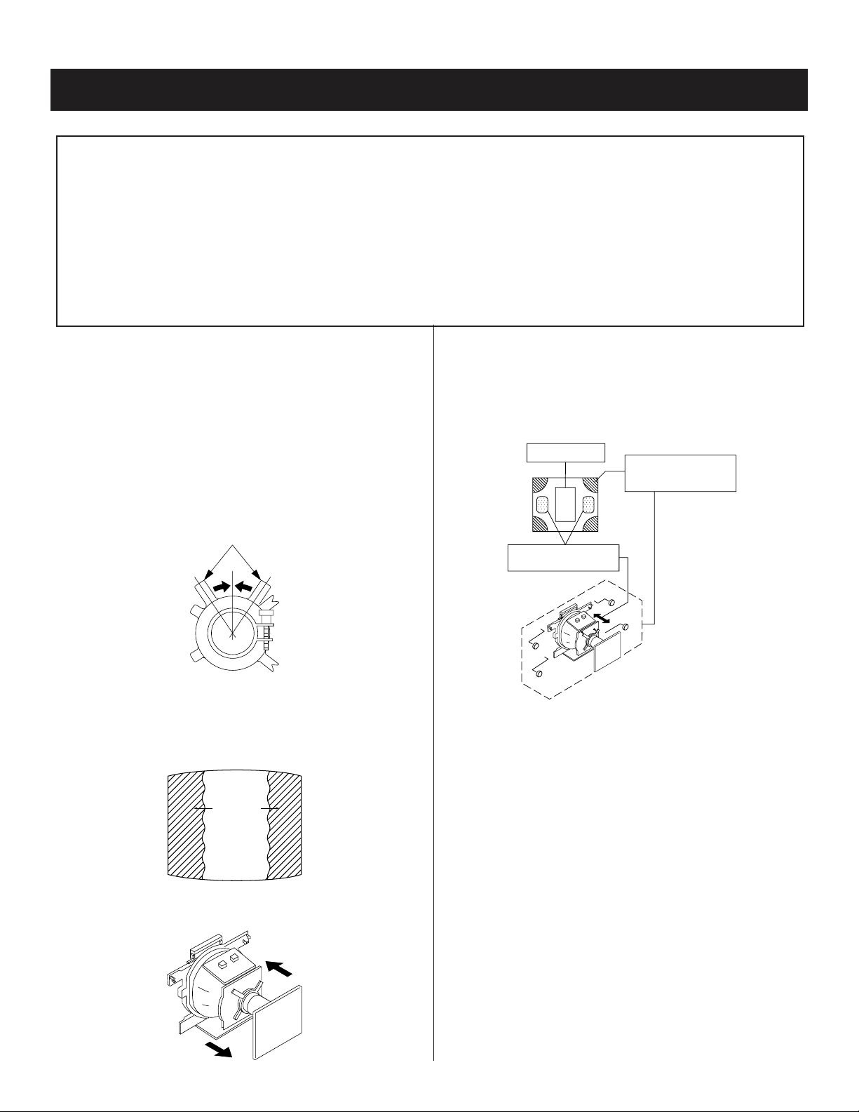
1. Input a raster signal with the pattern generator.
2. Loosen the defl ection yoke mounting screw, and set the purity
control to the center as shown below:
Purity control
Perform the adjustments in order as follows:
1. Beam Landing
2. Convergence
3. Focus
4. Screen (G2)
5. White Balance
Note Test Equipment Required:
1. Color Bar Pattern Generator
2. Degausser
3. DC Power Supply
5. Oscilloscope
6. Landing Checker
7. XCV Adjuster
4. Digital Multimeter
6. Switch over the raster signal to red and blue and confi rm the
condition.
7. When the position of the defl ection yoke is determined, tighten it
with the defl ection yoke mounting screw.
8. If landing at the corner is not right, adjust by using the disk
magnets.
Purity control
corrects this area.
a
b
d
c
Deflection yoke positioning
corrects these areas.
Disc magnets or rotatable
disc magnets correct these
areas (a-d).
3. Turn the raster signal of the pattern generator to green.
4. Move the defl ection yoke backward, and adjust with the purity
control so that green is in the center and red and blue are even on
both sides.
Blue
Red
Green
5. Move the defl ection yoke forward, and adjust so that the entire
screen becomes green.
b
c
a
d
KV-21FS140
12
KV-21FS140
2-2. CONVERGENCE
Before starting convergence adjustments:
1 Perform FOCUS, VLIN and VSIZE adjustments.
2. Set BRIGHTNESS control to minimum.
3. Set Picture mode to STANDARD.
4. Feed in dot pattern.
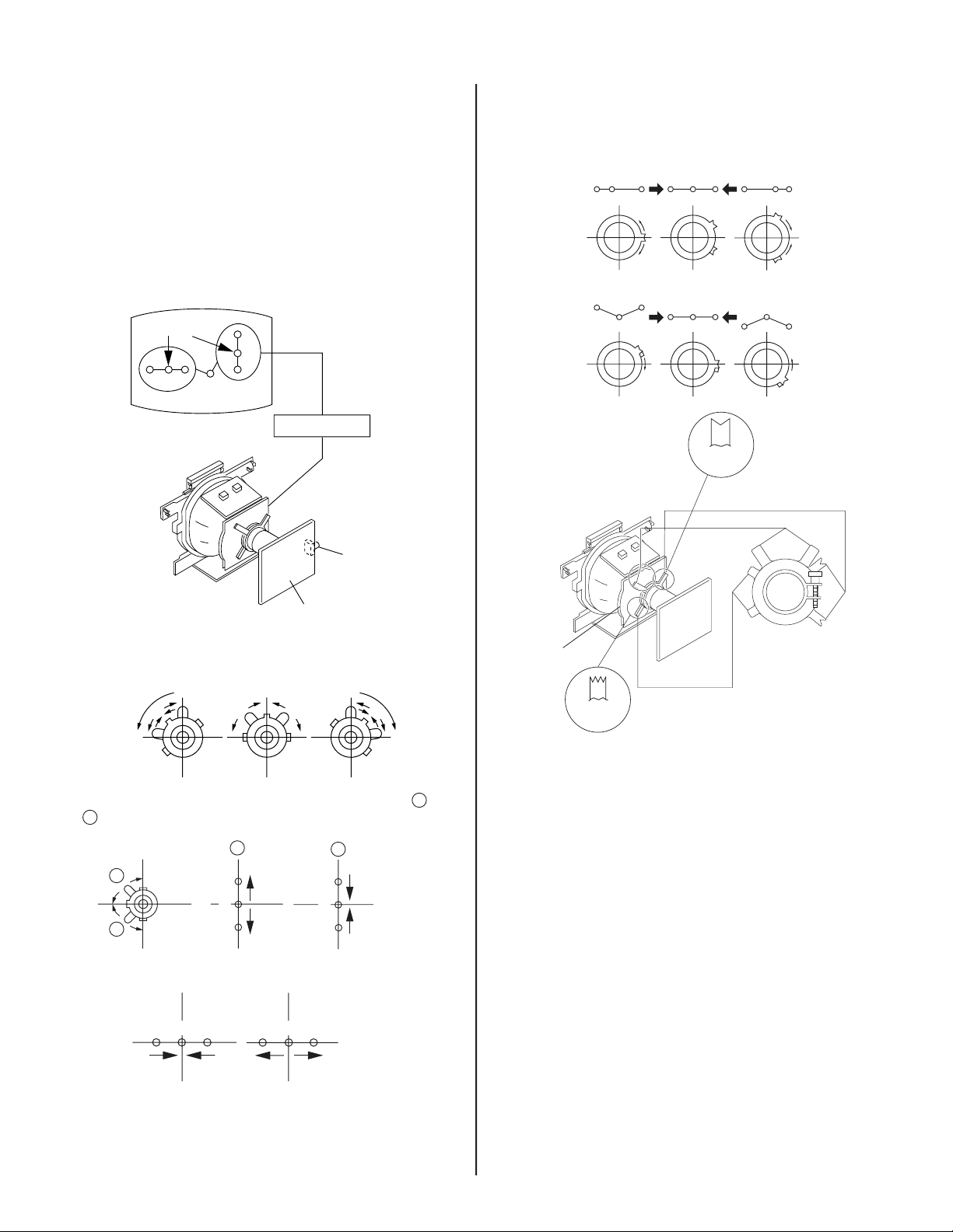
Vertical Static Convergence
1. Adjust the 4 pole magnet to converge red, green and blue dots in
the center of the screen.
Center dot
R G B
R
G
B
4 pole magnet
Horizontal Static Convergence
If the blue dot does not converge with the red and green dots, use the 6
pole magnet to adjust as shown:
RG B R G B R GB
RB
G
RG
RB
6 Pole
Magnet
6 Pole Magnet
Purity
GB
RV750
H. STAT
C/CV Board
2. Tilt the 4 pole magnet and adjust static convergence to open or
close the 4 pole magnet.
When the 4 pole magnet is moved in the direction of arrow A and
B
, the red, green, and blue dots move as shown below:
A
B
A
B
G
R
B
B
G
R
Moved RV750 (H.STAT)
DY pocket
4 Pole
Magnet
4 Pole Magnet
KV-21FS140
RGGRB
B
13
KV-21FS140
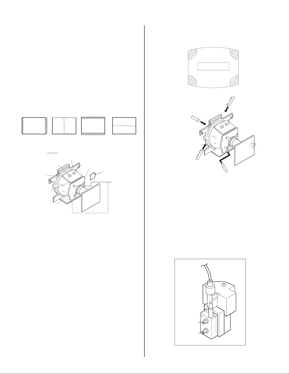
Convergence Rough Adjustment
Before performing this adjustment, perform Horizontal and Vertical Static
Convergence Adjustment.
Input cross hatch pattern.
a) TLH
Adjust the horizontal convergence of red and blue dots by inserting
TLH Correction Plate to the DY pocket (left or right).
b) YCH
Adjust YCH to balance Y axis.
c) TLV
Adjust YCh to balance Y axis.
d) XCV
Adjust XCV to balance X-axis.
YCH
DY pocket
RB
YCH
TLV
B
R
TLV
DY pocket
R
B
TLH Plate
XCV
XCV
B
R
TLH
ON DY:
TLV
XCV
Screen Corner Convergence
Affi x a Piece A (90), Convergence Correct/Permaloy Assy Correction to
the misconverged areas.
ba
a-d : screen-corner
misconvergence
cd
b1
a1
d1
a1~d1:Piece A (90), Convergence Correct
Permaloy Assy Correction
or
c1
2-3. FOCUS
FOCUS adjustment should be completed before White Balance
adjustment. (See 3-4. White Balance Adjustment)
1. Receive digital monoscope pattern.
2. Set Picture Mode to “DYNAMIC”.
3. Adjust focus VR to obtain a just focus at the center of the screen.
4. Change the receiving signal to white pattern and blue back.
5. Confi rm magenta ring is not noticeable. In case magenta ring is
obvious, then adjust FOCUS VR to balance magenta ring and
FOCUS.
KV-21FS140
FOCUS
SCREEN
14
2-4. SCREEN (G2)
1. Before beginning adustment procedure:
-Set Picture and Brightness to “STANDARD”.
-Set TV to Video mode.
-Set WHBL 016 “RGBB” to 01
2. Connect R, G, B of the C/CV board cathode to oscilloscope.
3. Adjust Brightness to obtain the cathode value to the value shown
below:
165 ± 2VDC
4. Adjust SCREEN VR on the FBT until the scanning line disappears.
5. Set WHBL 16 “RGBB” back to 00.
KV-21FS140
KV-21FS140
15
SECTION 3: CIRCUIT ADJUSTMENTS
Electrical Adjustments by Remote Commander
Use the Remote Commander (RM-YA005) to perform the circuit adjustments in this section.
Test Equipment Required: 1. Pattern generator 2. Frequency counter 3. Digital multimeter 4. Audio oscillator
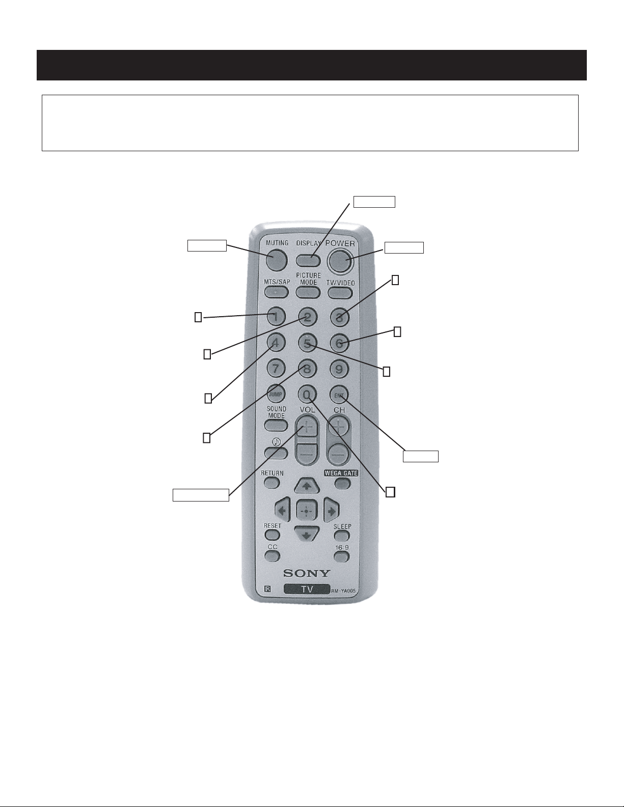
3-1. REMOTE ADJUSTMENT BUTTONS AND INDICATORS
DISPLAY
(Service Mode)
KV-21FS140
MUTING
(Enter into
memory)
1
Display next
Item
2
Display next
Category
4
Display previous
Item
8
(Initialize)
VOLUME (+)
(Service Mode)
POWER
(Service Mode)
3
Increase
Data value
6
Decrease
Data value
5
Display previous
Category
ENTER
(Enter into
memory)
0
(Remove
from memory)
KV-21FS140
RM-YA005
16
3-2. ACCESSING THE SERVICE MENU MODE
Use the remote commander to access the service meu mode and perform the following adjusments.
1. Standby mode (Power off).
2. Press the following buttons on the remote commander within a second of each other:
DISPLAY
Channel
5
Sound Volume +
The screen displays the fi rst service data category item.
POWER
KV-21FS140
category in decimal item name in decimal NG service command frequency video input name
GEOM 000 HPOZ 055 x SERVICE 60 VIDEO 1
release ID version in binary for factory color system (decimal)
STR31 7.11U 0011 1111 FF FF - - - - - 00084
000 00 00 0000 3E 40 000 004000 0000FF
item no. service data NVM field channel no./
software service data reserved power on time
Status Byte Status Byte
Flash DCXO #1 SSD #2 SSD
1. On the Remote Commander press 2 to select the next category, or 5 to select the previous category.
2. Press 1 to select the next item, or 4 to select the previous item.
3. Press 3 to increase the data value, or 6 to decrease the data value.
4. Press
MUTING
then 0 to write into memory.
GREEN
GEOM 000 HPOS 039 SERVICE 50 VIDEO 1
write with [MUTING].
GREEN
GEOM 000 HPOS 039 WRITE 50 VIDEO 1
Write executed with -.
RED
GEOM 000 HPOS 039 WRITE 50 VIDEO 1
Resetting the User Menus
Use the following procedure to reset the User Menus to the factory default settings.
1. Access Service Adjustment Mode.
2. Press 8 then 0 on the Remote Commander.
“WRITE” displays when
saving changes
“WRITE” becomes red
when saving, then changes
to “SERVICE”
KV-21FS140
17
KV-21FS140
3-3. CONFIRMING SERVICE ADJUSTMENT
CHANGES
1. After completing adjustments, pull out the plug from the AC outlet,
then replace the plug in the AC outlet again.
2. Access Service Adjustment Mode.
3. Using the buttons on the Remote Commander, locate the adjusted
items again to confi rm they were adjusted.
3-4. WHITE BALANCE ADJUSTMENTS
NOTE: FOCUS adjustment should be completed before White Balance
adjustment. (See 2-3. FOCUS)
1. Access Service Mode.
2. Input white raster signal using signal generator.
3. Set the following condition:
Picture “DYNAMIC”, PICT 006, note value of “WTS”
then change to 00.
4. Press 2 or 5 to select the WHBL category.
5. Press 1 or 4 to display the 03 “GDRV” and 04 “BDRV” items.
6. Press 3 or 6 to adjust for the best white balance.
7. At Cutoff, select WHBL 000 “BKOR” and 001 “BKOG” and adjust
the data.
8. Perform adjustment at Highlight and Cutoff condition until it reaches
its target.
9. Press
10. Set PICT 006 “WTS” back to its original data.
MUTING
then
ENTER
to save into the memory.
10. Set “PWL” and “BLBG” back to initial data.
(“PWL”: 01h and “BLBG”: 00h)
11. Press
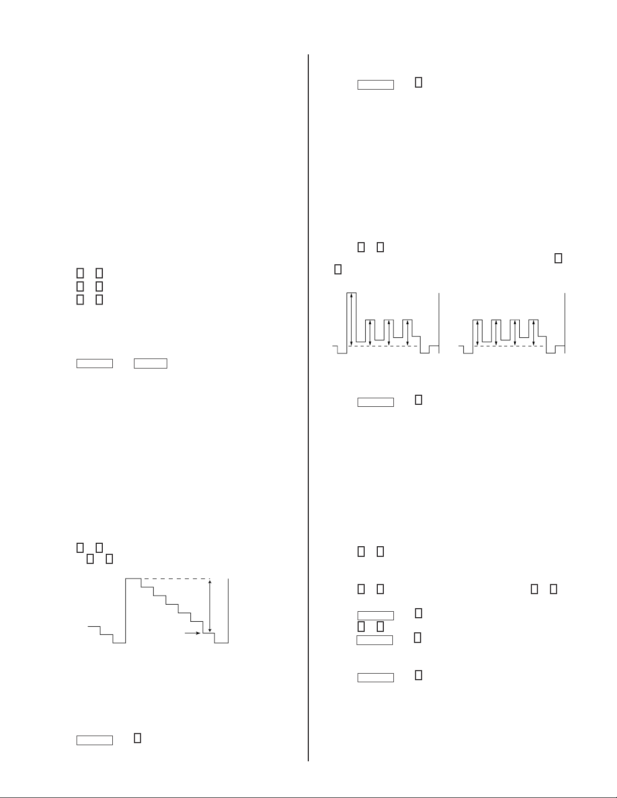
Sub Color Adjustment
1. Set TV to Video mode.
2. Set Picture mode to “CUSTOM”.
3. Input PAL 100% Color Bar (CB) to TV set (OTHER MODEL).
4. INPUT NTSC 75% CB to TV set (NTSC MODEL).
5. Set PICT 006 “WTS” to 00h and Intelligent Picture to “OFF”.
6. Set the following condition:
PICTURE 50%, COLOR 50%, BRIGHTNESS 50%, HUE 50%,
7. Connect an oscilloscope to pin
8. Press
MUTING
SHARPNESS 50%
1
or 4 to select SADJ 004 “SCOL”, then adjust
B2=VB3=VB4
V
6
, then write in the data +5 step offset.
VB1
VB2 VB3 VB4 VB1 VB2 VB3 VB4
VB2 = VB3 = VB4 (for PAL) VB1 = VB4 (for NTSC)
then 0 to write into memory.
2
(B Output) of CN004.
(for PAL),
VB1 = VB4 (for NTSC)
(Difference is within 70mV)
by pressing
3
or
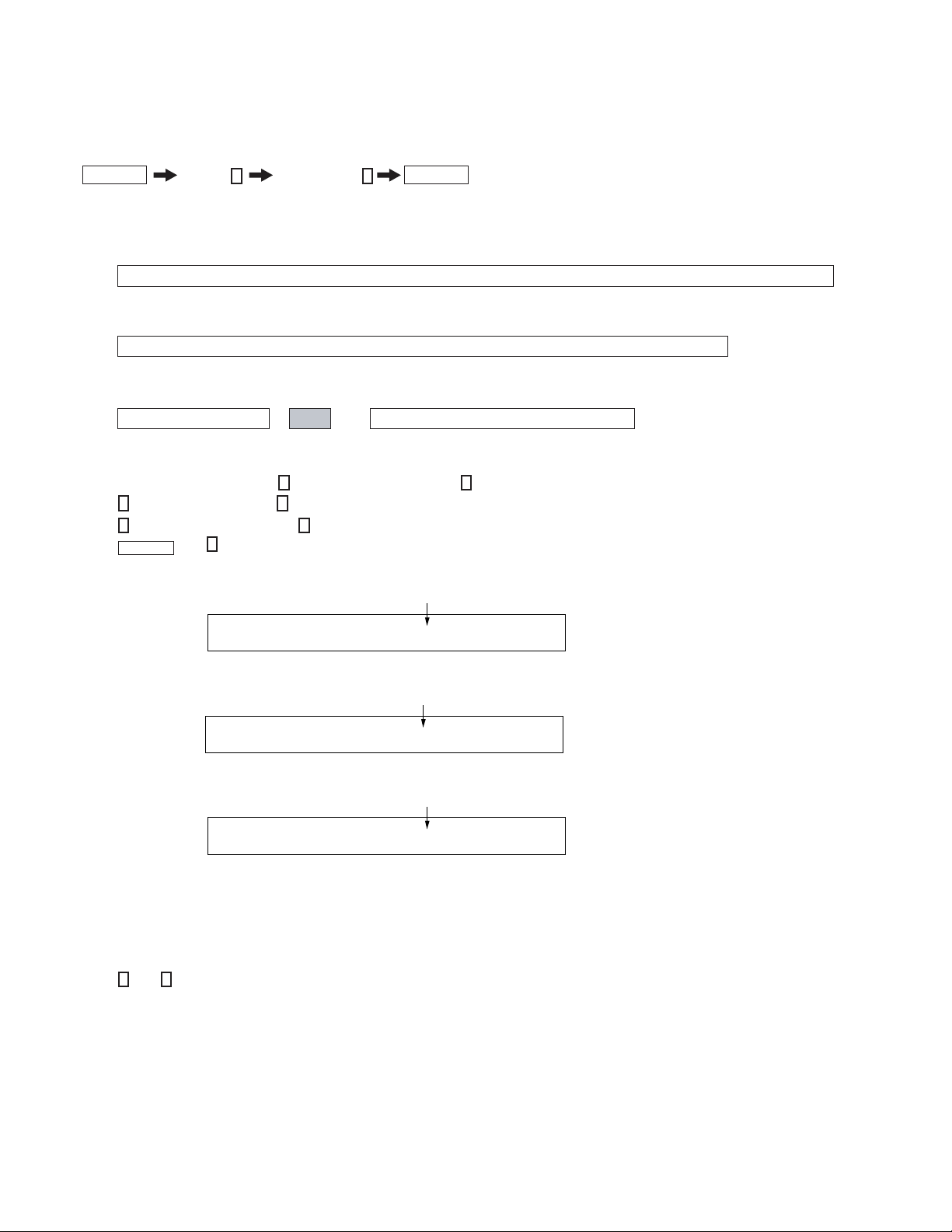
3-5. PICTURE QUALITY ADJUSTMENTS
P Max/Contrast Adjustment
1. Set TV to Video mode.
2. Set Picture mode to “CUSTOM”.
3. Input PAL 100% CB to TV set (OTHERS), NTSC 75% CB (NTSC
model).
4. Set PICT 003 “PWL” to 00h WHBL 017 “BLBG” to 01h.
5. Set the following condition:
PICTURE 100%, COLOR 0%, BRIGHTNESS 50%
6. Connect an oscilloscope to pin
1
7. Press
pressing 3 or 6 until the spec below:
or 4 to display SADJ 000 “PMAX”, then adjust VR by
1.46 ± 0.03 Vp-p = For 21" without VM models
1.65 ± 0.03 Vp-p = With VM models except NTSC models
1.23 ± 0.03 Vp-p = NTSC models VM models
1.10 ± 0.03 Vp-p = For 21" NTSC non VM models
4
(R Output) of CN004.
VR
Black
9. Press
10. Set “WTS” back to original data and Intelligent Picture to “ON”.
11. Copy no.9 data to PAL TV & DVD mode.
MUTING
then 0 to write into memory.
Sub Hue Adjustment
1. Set TV to Video mode.
2. Set Picture mode to “CUSTOM”.
3. Input NTSC 3.58 CB to TV set.
4. Set the following condition:
PICTURE 50%, COLOR 50%, BRIGHTNESS 50%, HUE 50%,
SHARPNESS 50%
5. Press 1 or 4 to select service mode and - 5 step offset from SADJ
004 “SCOL”.
6. Connect oscilloscope to pin
1
7. Press
8. Press
9. Press 1 or 4 to select SADJ 004 “SCOL” and +5 step offset, then
10. Select TV channel with 3.58 and repeat item (3) to (7) and +1 step
11. Press
or 4 to select SADJ 001 “SHUE”, then press 3 or 6 to
adjust the data.
MUTING
press
MUTING
data offset.(NTSC model)
MUTING
then 0 to write into memory.
then 0 to write into memory .
then 0 to write into memory.
2
(B output) of CN004.
8. Select Wide Mode to “ON” in TV and Video mode and write “PMAX”
data - 8 steps (for models with V-Compression features only).
9. Press
MUTING
then 0 to write into memory.
KV-21FS140
18
KV-21FS140
12. For single system model with NTSC 4.43, select TV channel with
NTSC 4.43 and repeat items (3) to (8)
VB3
VB1
VB2
VB4
80mV
The highest level of VB1, VB2, VB3, VB4
must be aligned at the same time.
The ideal difference between
V
B2 and VB3 is within ± 80mV
13. Once adjustment is completed in Video mode, carry out adjustment
in DVD mode. Set TV to DVD mode. Input NTSC 3.58 CB to DVD
set and perform steps 4 to 9 and 11.
Sub Bright Adjustment
1. Set TV to RF mode.
2. Input PAL monoscope to RF mode.
3. Set Brightness 50% and Picture to “MINIMUM”.
4. Press 1 (or 4) to select WHBL 010 “SBRT”.
5. Press 3 to increase the data value, or 6 to decrease the data value
so that the cut-off level is 10 IRE, slightly glimmer: 20 IRE.
6. Press
MUTING
then 0 to write into memory.
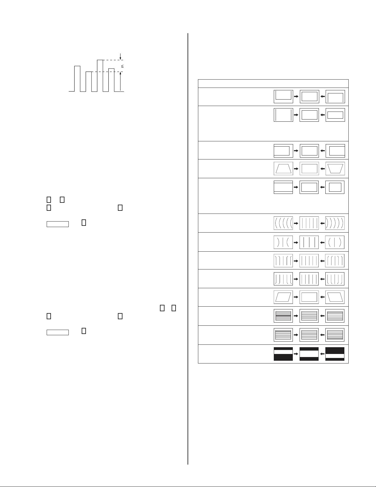
PAL 50HZ NORMAL MODE
1. Input PAL signal 50Hz in the Service Mode.
2. Set Wide Mode to “OFF”.
3. Perform the below adjustments using the “General Setting”
sequence.
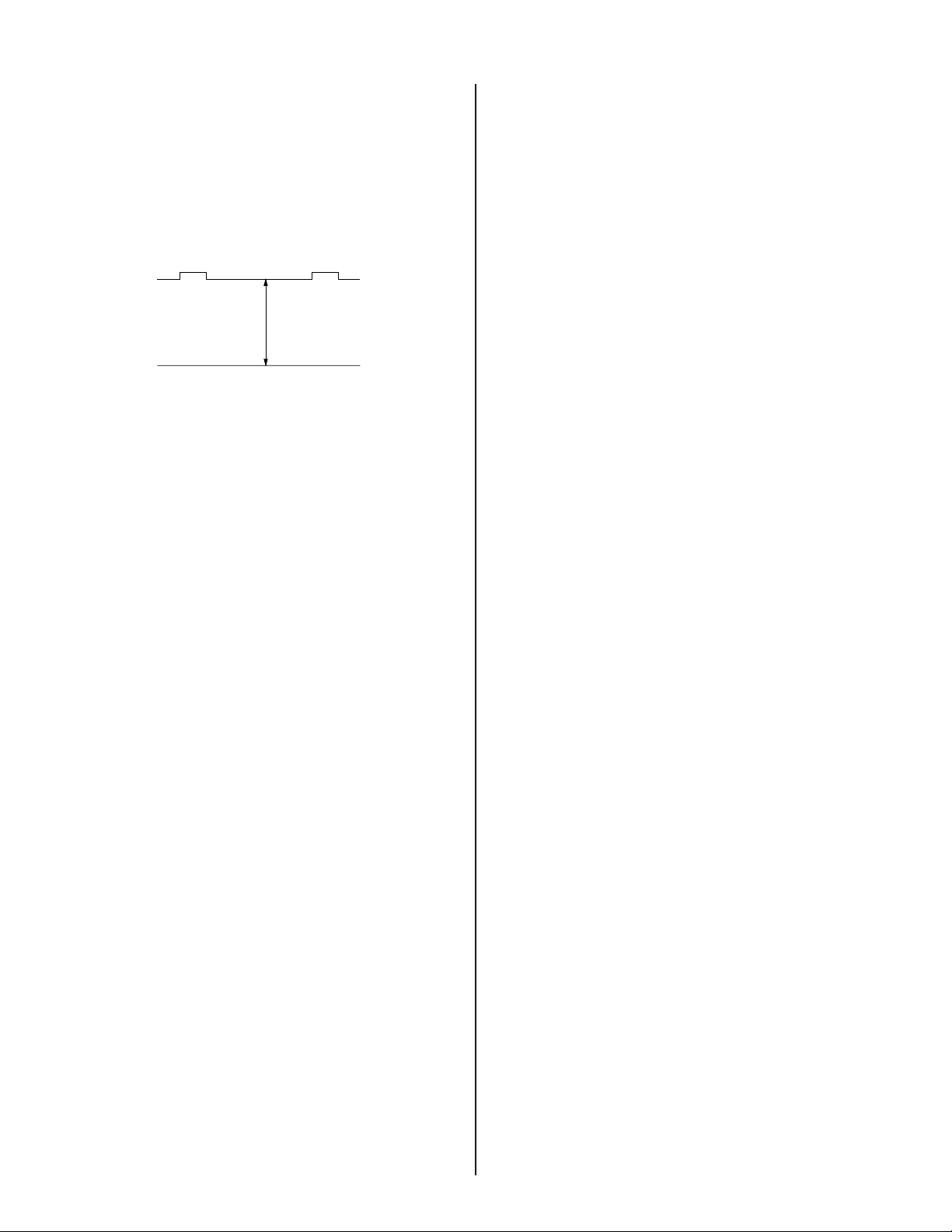
Item No. Function Illustration
GEOM 013 Vertical Shift
(VPOS)
GEOM 011 Vertical Amplitude
(VSIZ)
Note: Adjust VSIZ to
12.4
±
(SPCB)
11. 3
(PAL Monoscope)
±
11. 5
±
(NTSC Monoscope)
GEOM 000 Horizontal Shift
(HPOS)
GEOM 009 EW Trapezoid
(EWTZ)
GEOM 005 EW Width (EW)
(HSIZ)
GEOM 002 Horizontal Bow
(HBOW)
Note: Adjust HSIZ to
±
16.4
(SPCB)
±
14.6
(PAL Monoscope)
±
(NTSC Monoscope)
15.3
Geometry Adjustment
Geometry adjustment must be done for both color systems PAL and
NTSC.
General Setting
1. Input Monoscope or Special Color Bar (SPCB) signal using a
pattern generator.
2. Access Service Mode.
3. Select the category item that needs adjusting by pressing 1 or
4. Press 3 to increase the data value, or 6 to decrease the data
value.
5. Press
MUTING
then 0 to write into memory.
NOTE: Geometry Adjustment must be performed for 4 different modes:
PAL 50Hz NORMAL MODE,
PAL 50Hz WIDE MODE,
NTSC 60Hz NORMAL MODE,
NTSC 60Hz WIDE MODE.
4
GEOM 006 EW Parabola/Width
(EWPW) (PW)
GEOM 007 EW Upper Corner
(UCOP) Parabola
GEOM 008 EW Lower Corner
(LCOP) Parabola
GEOM 001 Horizontal
(HPAR) Parallelogram
GEOM 012 S-Correction(SC)
(SCOR)
GEOM 003 Vertical Linearity
(VLIN)
GEOM 004 Vertical Scroll
(VSCR)
4. After completing the adjustments for PAL 50Hz NORMAL MODE,
set Wide mode to “ON”, and copy all PAL 50Hz NORMAL MODE
adjusted data to PAL 50Hz WIDE MODE except VSCR.
5. Complete the adjustment for NTSC 60Hz NORMAL MODE.
6. Set Wide mode to “OFF”.
7. Complete the adjustment items listed in the above table using the
“General Setting” sequence.
8. After completing the adjustments set Wide mode to “ON” and copy
all NTSC 60Hz NORMAL MODE adjusted data to NTSC 60Hz
WIDE MODE except VSCR.
9. After completing all the adjustments, reconfi rm VSIZ and VPOS.
KV-21FS140
19
dAel
J
VyT
t
i
la
no
i
t
cn
u.F
t
ine
Ign
a
nRo
i
t
cn
u
e
F
t
o
N
&e
lb
aeTmaN
eci
v
enDo
mmo)C
d
el
i
ateD(e
u
laVl
a
it
inI
yrog
eta.
C
oe
NmacNec
DeD 05)3:4
0
(6)
3:
40(5w)
3:
4
0
(
6w
)
3:
4(
MO
E
0
G0
S0O
P1
H
33
0
6)
0
S
H(tf
i
h
S
lat
no
ziro
H >)Z/F/N/
Z
W(
*)
0
6/
0
5(
n
eerc
S9:
6
1<
>06
w/
05
w/
06/
05ne
er
c
S3:
4< ros
s
ecorP-VT
11
313133
10R
0A
P1
H33
06
m
0argole
l
lar
a
P
l
a
t
no
z
iro
H
>)Z/
F/N/Z
W(*)
06/05(ne
er
cS9:
61
<>
06
w
/
05
w/
0
6/
05ne
er
c
S3:
4<
113
13133
20W
0
O
B
1H
3
3
06 w0o
B
l
atn
o
ziro
H
>)Z/F/N/Z
W(*)0
6
/05(neer
cS9:
61
<
>
06
w/
0
5
w/0
6/
0
5neerc
S3:4
<
113
13133
30N
0IL
1V3306 y
0
t
ir
aen
i
L
lac
i
treV
>)Z
/F
/
N
/ZW(*)
0
6/
0
5(
n
e
er
cS
9:61<>06
w/0
5
w
/06
/05n
eerc
S
3
:4
<
113
13133
40R
0C
S1
V3306 l
0l
or
c
S
l
a
c
i
tre
V >)
Z/
F/N/
ZW(*)06/05
(
neer
cS9:
6
1
<
>0
6w
/0
5w
/06
/05n
eerc
S3:4
<
11
3
13
133
5
0
Z
0
I
S1
H33
06 )0W
E(ht
d
iWW
E
>)Z/F/N/
ZW(*)
0
6/05(neercS9:6
1<>
06w/
05w/
0
6/
05ne
er
c
S3:
4
<
11313
133
60
W
0PW
1E3
3
0
6
)0W
P(htdiW/alob
a
ra
PW
E
>)Z/F/
N
/ZW(*)
06
/
05(neercS9:
6
1<>
06w/05w/
0
6/
0
5nee
r
c
S3:
4
<
11313
133
70P0OC7U
1
306 a
0
l
obar
a
P
r
enr
o
C
re
pp
UW
E >)
Z/
F/N/Z
W
(
*)
06
/0
5(n
eercS9:61<
>
06w/0
5w/
0
6/
0
5n
e
er
c
S3:4
<
77
1
71
711
80P
0
OC
7L1306 a0l
o
bar
a
P
r
enr
o
Cre
w
oLW
E >)Z/F/N/ZW
(
*)
0
6/
05(n
e
erc
S
9
:
61<>
06w/
0
5w/06/0
5
neer
c
S3:4
<
77171
711
90Z0TW1
E
3306 m
0
u
i
z
ep
arTW
E >)Z/F/N/
Z
W(
*)
0
6/
0
5(
n
eercS9:6
1<>
0
6w/05
w
/06
/
05n
eercS3:
4
<
1131313
3
0
1P0LS1
V3
30
6
)
0S
V(epol
S
lac
itr
e
V
>)
Z/F/N/ZW(*)0
6/
0
5(ne
er
cS9:61
<
>06w/
0
5w/
06
/
05neercS3:
4<
113
1
3
133
11Z0
I
S5
V1306 e0
d
ut
ilpm
A
la
c
itr
e
V >)Z
/
F/N/ZW(*)06/
0
5(
n
e
er
cS
9
:
61<>
0
6w/
05w/06/
0
5ne
er
cS
3
:
4
<
551
5
1
511
21R
0
O
C4
S1306 )
0
CS(
n
o
itcerr
o
C-
S
>)Z/
F/N/
Z
W(*)06
/
05(n
e
er
cS9:6
1
<>06w/
0
5w/0
6
/0
5ne
er
cS3:4<
44141
411
31S
0OP1
V3306 )
0
H
S
V(
t
f
ih
S
l
a
citre
V >)Z
/
F/N/ZW(*)06/
0
5(
n
e
er
cS
9:61<>
0
6w/0
5w/
0
6/0
5n
eercS
3
:4<
11
3
13133
41M
0OZ1
V330
6
)
0
Z
V(
m
ooZ
lac
it
r
e
V
>)Z
/F/N/ZW(*)06
/
05(n
eercS9:6
1
<
>
0
6w/05w/06
/
05n
eercS
3
:4<
51L0B
0H
0
100 e0
doMgn
i
k
n
a
l
B
B
G
R >)Z
/
F/N/ZW
(
*)06/
0
5(
n
e
er
c
S9:61<>
0
6w/0
5w/
0
6/05
n
eercS
3
:4<
1
10
10100
6
1F
0B7W0501 )0
FB
W(g
ni
k
n
a
l
BediWfogni
miT
>)Z
/F
/
N
/Z
W(*)06/05(n
e
er
cS9:61
<
>0
6w/
05w
/0
6/
05neerc
S
3
:
4
<
77
0
707
00
71R
0B7W05
01 )0RB
W(
g
nikn
a
lBediWfogn
i
miT >)
Z
/F/N/
ZW(*)
0
6/05(neercS
9
:6
1<>0
6w
/05w/06/
0
5ne
er
cS3:
4<
04
1
01411
81L0
B0
S01
0
0g
0nik
na
l
Be
c
i
vr
e
S
>)
Z/F
/N/ZW(*)06/
0
5(ne
er
cS9:
61<>06w/0
5w/
06
/
05n
eercS3:4< 0
0
91Y
0P
O
0C
0
10
0a0er
a
MV
NzH
06/
0
5
l
l
aotatadOE
Ge
ht
y
p
o
C >)
Z/F/N/ZW(*)0
6/
05
(
n
e
er
cS9:61<>0
6w/05
w
/06/05n
e
er
cS3:4< 0
0
O
N
ET
)a .atad ledo
n
i eht
I
.
/"(
oN
b.a
t
)
me
r
I
)
c
)
S
t
d
na
etoN
)e
Ib t
eht
n
N
)f
T
S
lai
tin
v
m
)"
ae
sn
a
me
kr
e
ahs
i
ded
rad
tad
d
f
ro
esac
v
C
f
o
baT
hsals eh
ra
la
" d
"
*
s
met
il
a
ff
re
iD eht
N61.6 re
.
iated( eu
tad
si
a
*
dna
,"
"
*
e
ra
.
on
atad
eht
no dets
A
ht ataD tne
vrassecen si
ed a
lper
eci
,nmu
loc )del
o
f nommoc
r
r e
saelp
fe
ujd
ra eso
dna itluM
re
tI
tnemts
me
T
ts eht e
sujda ,tnemeca
mt
t re
tfa atad eht
N
ST
2
rof 5
egap
el
ba
r
adna
ad d
r
y
ne
m
ledom C
tad eht
f
er era
v at
nit
rwe
i
ecnere
v
eula v
g
eht
/"( k
)"
fe
s
r
re
ot
fereht ,seula
ro
ht n
tirw s
net
o
atad
i
m e
eulav
m C
S
TN
ref
t
e
i
po
rc
r
co
f
eb
yam
id
rosse
. romem
s rof
y
tne
ferehT
ro
mo
hcae rof
m
ad
eht ,e
.smeti e
met
I t
ne
mtsuj
KV-21FS140
f
dna
ledo
ro
hcae
seulav at
.
edom
sledom eht fo
itcepser derots era
yle.y
eht ni
KV-21FS140
20
KV-21FS140
JV
y
Tt
i
lan
o
itcnu
.
F
tineI
gna
n
R
oitcnu
e
F
toN&elb
a
eTmaNe
cive
nDo
mmo
C
)
de
l
iateD(eulaVla
it
i
nI
y
r
ogeta.C
o
e
N
ma
c
N
e
c
D
e
D
VU
l
Y
ap05
)
VT(
lap05
)oedi
V
(
maceS05
)VT(
maceS05
)oediV(
VT0
0
6
6
)oed
iV
(
VUY0
V
5U
Y
0
B6G
R0
B
5
GR0e6domciP
0
ed
omciP
1
edomciP
2
VoTe
d
iV
ediWVT
)3:4(
e
d
iWoediV
)3
:
4(
J
DA0S0X0
AM
3
P
6306
m0u
m
ixaMe
rutciP >edi
W/lamroN</)ediW/la
mroN(*)oediV/VT
r(o
sseco
rP-VT
7
7
37
3
733
1
0E
0
U
H
7
S
0
5
0
1e0u
H-buS oediV/VT
7
70
0
20
P
0
HS
5S
1
3
0
6
s
0
senprahS-buS V
UY/oediV/VT
24
0
2
4
4
30
O
0
HS
0
S
0
7
0
0
)
0
c
iP
tnegi
l
le
t
nI(t
e
sf
f
Ossen
pr
ah
S-buS e
no6n0
40
L
0
OC
1S
3
3
0
6r0o
l
o
C-buS /
)o
ed
iv(maces05/)vt
(mace
s
05/)oediv(lap05/)
vt
(lap
05
BGR06/BGR
05/V
UY
06/VUY0
5/oediv06
/VT06
0
1
003
10131
30
3
1
00
31
0
3
50
O
0
OC
0S
030
0
)
0
ci
Pt
neg
illetnI(tesffO
roloC
-b
uS
eno
2
n
0
60
C
0
I
1
P
3
7
02 ;
1
)dilavni(0
0
1>;
)di
lav(001
~0:AG[lort
no
C
e
rutc
iP
]
)
dilavni(6t
ib
e
rongi;)dila
v
(3
6~0:srehtO
)ata
D
t
e
s
e
R
resU=lanos
reP:AG(
le
doMerutciP
000108
8
7
0
L
0
O
1C
3
7
0
2;
1
)dilavn
i(001>;)dilav(
001
~0:A
G[lortnoCr
o
l
o
C
])dilavni(6tiberongi;)d
ilav(36~0:sreht
O
)ataDtes
eRres
U
=
lanosreP:AG
(ledoMe
ru
tciP
6
09
055
80
T0
R
1
B
3702
;
1)dilavni
(001
>;
)dilav(001~0:AG[lo
rtnoCssenthgi
rB
]
)dilavni(6
t
ib
e
ro
ng
i
;
)di
lav(36~0:srehtO
)ataD
tese
Rre
sU=lan
osreP:AG(
ledoMerutc
iP
0
0
5
0
5
5
90
E0
U
1H
3
7
02 ;
1
)dilavn
i
(
001>;)dila
v
(00
1
~0:A
G[lortnoCeuH
])d
ilavn
i(6tibe
rongi;)dila
v(36~0:srehtO
)
le
do
mS
Uht
iw)0-5(hE1#TNI
TotdneS*(
)ataDteseRresU=lanos
reP:AG(ledo
Me
r
ut
ciP
00505
5
0
1
P
0
H
1
S
3
7
0
2
;
1
)dilavni(001>;)dilav(001~0:AG[lo
rtnoCssenprahS
])dila
vni(6tiberongi;
)d
ilav(36~
0:
s
rehtO
)at
a
DteseRre
s
U
=
l
anos
reP
:AG(ledoMe
rutciP
0
0
60
5
5
JVyTtil
a
noi
t
cnu
.
Ftin
eI
g
nanRoi
t
cn
ue
F
toN&el
b
a
eT
maNe
civ
e
n
D
omm
oC )d
e
l
i
a
teD(eu
l
aVlaitinI
yr
og
e
ta
.C
oeNmacNe
c
DeD
pmeTloC
)r
ehtoLOOC
(
pme
Tl
oC
)rehtoMRA
W
(
pmeTlo
C
L
AR
TUEN(
)reh
to
pme
TloC
)VUYLOOC(
pmeTloC
)VU
Y
MR
AW
(
pm
eTl
oC
LARTUEN(
)VU
Y
VU0
Yedomci1
P
e
d
omc
i2
P
e
d
omc
iV
PoTediV
LBH0W0
R0O
K
1
B
3
3
0
6)
01
0=BFO(Bte
s
f
fO,)0
0
=BFO(Rte
s
ffOle
ve
L
k
c
a
l
B )
s
re
htO/BG
R
/
VU(*)la
m
roN
/WOL/HGIH(pme
tl
o
rcos
se
corP-V
T
1
1
3131313133
10
G
0O
K
1B
3
30
6G0t
e
s
f
fOl
ev
e
L
k
calB
)
sr
eh
tO/
BGR
/VU
(
*
)
l
a
mro
N
/WOL
/HGIH(pmetlo
c
113131313133
20V0R
D7R330
6
R
0
t
n
i
oPetihW
)
s
r
eh
tO
/B
G
R
/VU
(
*
)
l
a
m
r
oN
/WOL
/
HGIH(p
me
t
lor
c
osse
c
o
r
P
-
VT
77373
7373733
3
0
V
0
RD7G330
6G0tni
o
P
e
tihW
)s
rehtO
/BGR
/
V
U
(
*
)
l
amr
oN
/
WO
L
/H
G
IH(
p
m
e
tl
oc
773737373733
4
0V0RD
7
B
33
0
6B0tnioP
e
t
i
h
W )
sr
e
h
tO
/BGR/
V
U
(*)lam
r
oN
/
WO
L
/HG
IH
(
pmetloc
773
73737373
3
5
0G0P0
L
0100 t
0e
s
er
P
n
i
aG
BGR eno1
n0
60
R
0G1P370
2)1RG
P
(Rn
i
aGtese
r
P
en
o0
n4
70
G0G1
P
370
2)1GG
P
(G
n
iaGt
e
serP
en
o0n4
80
B0G1P37
0
2)1BGP(Bn
i
aG
t
e
serP en
o
0n4
90
F
0
ON0G05
0
1t0esf
fO
n
i
aGte
serP eno
p
noolCC
5C1
01
T
0
R
B
1
S
330
6
s
0se
n
th
g
irB-buS VUY/BGR/sr
e
h
tO
13
1133
11O0
RB0S
03
0
0)0ciPtnegil
l
e
tn
I
(te
s
f
fO
ssenthgirB-buS en
o
2
n0
21L
0
G
0
E
0
1
0
0m0etsy
S
CC
Cni
p
ooLn
i
aGelb
anE en
o
0n0
3
1L0G0
S
0300 m
0ets
y
S
CC
C
n
it
nerruChgiHfono
itc
e
l
e
S en
o
0
n
0
4
1
B0
K
0A
010
0
n
0
oitazil
i
ba
t
St
nerr
uC
kcalB
en
o
0n0
51
S0
B
0C010
0g0
n
i
ti
miL
t
n
e
rruCmaeBfo
e
c
neu
q
eSlort
n
oC en
o
0n0
61
B
0BG
0R03
00 g
0niknalB
BGR
e
no
0n0
71G
0
BL0B01
0
0t0u
p
t
uO
n
eerG&
e
u
l
Bfognik
nal
B
eno0
n
0
81B0F0
O
01
0
0e0ul
B
tesffOl
ev
eLk
calB
e
no1
n
0
91R0B
S0N0501 t0esffOssenth
g
ir
Bdra
d
na
t
SnoN
eno
0n
0
0
2P
0B
0
W03
00
)
0
woL:3,2,lamroN:1,h
g
iH
:
0(
g
n
it
t
eSpme
T
r
o
l
oC
e
do
M
er
u
t
c
i
P
0
1
010
0
KV-21FS140
21
 Loading...