

SONY KV-21FK120 Service Manual

HISTORY INFORMATION FOR THE FOLLOWING MANUAL:
SERVICE MANUAL
MODEL NAME REMOTE COMMANDER DESTINATION CHASSIS NO.
KV-21FK120
RM-Y194 LATIN NORTH SCC- S73H-A
BA-6
CHASSIS
ORIGINAL MANUAL ISSUE DATE: 4/2005
REVISION DATE SUBJECT
4/2005 No revisions or updates are applicable at this time.
TRINITRON® COLOR TELEVISION
9-965-980-01

Self Diagnosis
Supported model
SERVICE MANUAL
MODEL NAME REMOTE COMMANDER DESTINATION CHASSIS NO.
KV-21FK120
RM-Y194 LATIN NORTH SCC- S73H-A
BA-6
CHASSIS
9-965-980-01
KV-21FK120 RM-Y194
TRINITRON® COLOR TELEVISION

TABLE OF CONTENTS
SECTION TITLE PAG E
Specifi cations ............................................................................................................................................................................. 4
Warnings and Cautions .............................................................................................................................................................. 5
Safety Check-Out ....................................................................................................................................................................... 6
Self-Diagnostic Function ............................................................................................................................................................. 7
SECTION 1: DISASSEMBLY ............................................................................................................................................................. 9
1-1. Rear Cover Removal .......................................................................................................................................................... 9
1-2. Chassis Assembly Removal ............................................................................................................................................... 9
1-3. Service Position ............................................................................................................................................................... 10
1-4. Picture Tube Removal .......................................................................................................................................................11
Anode Cap Removal Procedure .......................................................................................................................................11
Wire Dressings ................................................................................................................................................................. 12
SECTION 2: SET-UP ADJUSTMENTS ............................................................................................................................................ 17
2-1. Beam Landing .................................................................................................................................................................. 17
2-2. Convergence .................................................................................................................................................................... 18
2-3. Focus ............................................................................................................................................................................... 19
2-4. Screen (G2) ...................................................................................................................................................................... 20
SECTION 3: SAFETY RELATED ADJUSTMENTS ......................................................................................................................... 21
3-1.
X
R565 Confi rmation Method (HV Hold-Down Confi rmation) and Readjustments ........................................................21
3-2. B+ Voltage Confi rmation and Adjustment ........................................................................................................................ 21
KV-21FK120
SECTION 4: CIRCUIT ADJUSTMENTS .......................................................................................................................................... 23
4-1. Remote Adjustment Buttons and Indicators ..................................................................................................................... 23
4-2. Accessing Service Adjustment Mode ............................................................................................................................... 23
4-3. White Balance Adjustments ............................................................................................................................................. 24
4-4. Memory Write Confi rmation Method ................................................................................................................................ 24
4-5. Service Data List .............................................................................................................................................................. 25
4-6. ID Map Table .................................................................................................................................................................... 33
4-7. A Board Adjustments ........................................................................................................................................................ 34
SECTION 5: DIAGRAMS ................................................................................................................................................................. 37
5-1. Circuit Boards Location .................................................................................................................................................... 37
5-2. Printed Wiring Board and Schematic Diagram Information .............................................................................................. 37
5-3. Block Diagram and Schematics ....................................................................................................................................... 38
A Board Schematic Diagram ............................................................................................................................................ 39
CV Board Schematic Diagram ......................................................................................................................................... 41
KR Board Schematic Diagram ......................................................................................................................................... 42
HK Board Schematic Diagram ......................................................................................................................................... 44
5-4. Semiconductors ............................................................................................................................................................... 45
SECTION 6: EXPLODED VIEWS .................................................................................................................................................... 46
6-1. Picture Tube ..................................................................................................................................................................... 46
6-2. Chassis ............................................................................................................................................................................ 47
SECTION 7: ELECTRICAL PARTS LIST ....................................................................................................................................... 48
KV-21FK120
3
SPECIFICATIONS
p
)
p
KV-21FK120
Power Requirements 120V, 60Hz
Number of Inputs/Outputs
eaker Output(W
S
Power Consumption (W)
In Standby (Max)
Dimensions (W x H x D)
Mass
Television system
American TV standard, NTSC
Channel coverage
VHF: 2-13/ UHF: 14-69/ CATV: 1-125
Y,P
Microphone 2
Head
In Use (Max) 140W
1)
Video
, P
B
Audio
2)
R
3)
2
1
3
10W x 2
hones
4)
1
1W
mm 631 x 468 x 491 mm
in
24
7/8
x 18
3/8
kg 25.4 kg
lbs 56 lbs
1) 1 Vp-p 75 ohms unbalanced, sync negative
2) Y: 1.0 Vp-p, 75 ohms unbalanced, sync negative;
PB: 0.7 Vp-p, 75 ohms
PR: 0.7 Vp-p, 75 ohms
3) 500 mVrms (100% modulation), Impedance: 47 kilohms
4) This specifi cation is maximum wattage.
x 19
1/4
KV-21FK120
in
Picture tube
FD Trinitron® tube
Visible screen size
20-inch picture measured diagonally
Actual screen size
21-inch measured diagonally
Antenna
75 ohm external terminal for VHF/UHF
Supplied Accessories
Remote Commander RM-Y194
Two Size AA (R6) Batteries
Antenna, Telescopic
Microphone
Converter
Cord with Connector
Video 2 Cable Adaptor
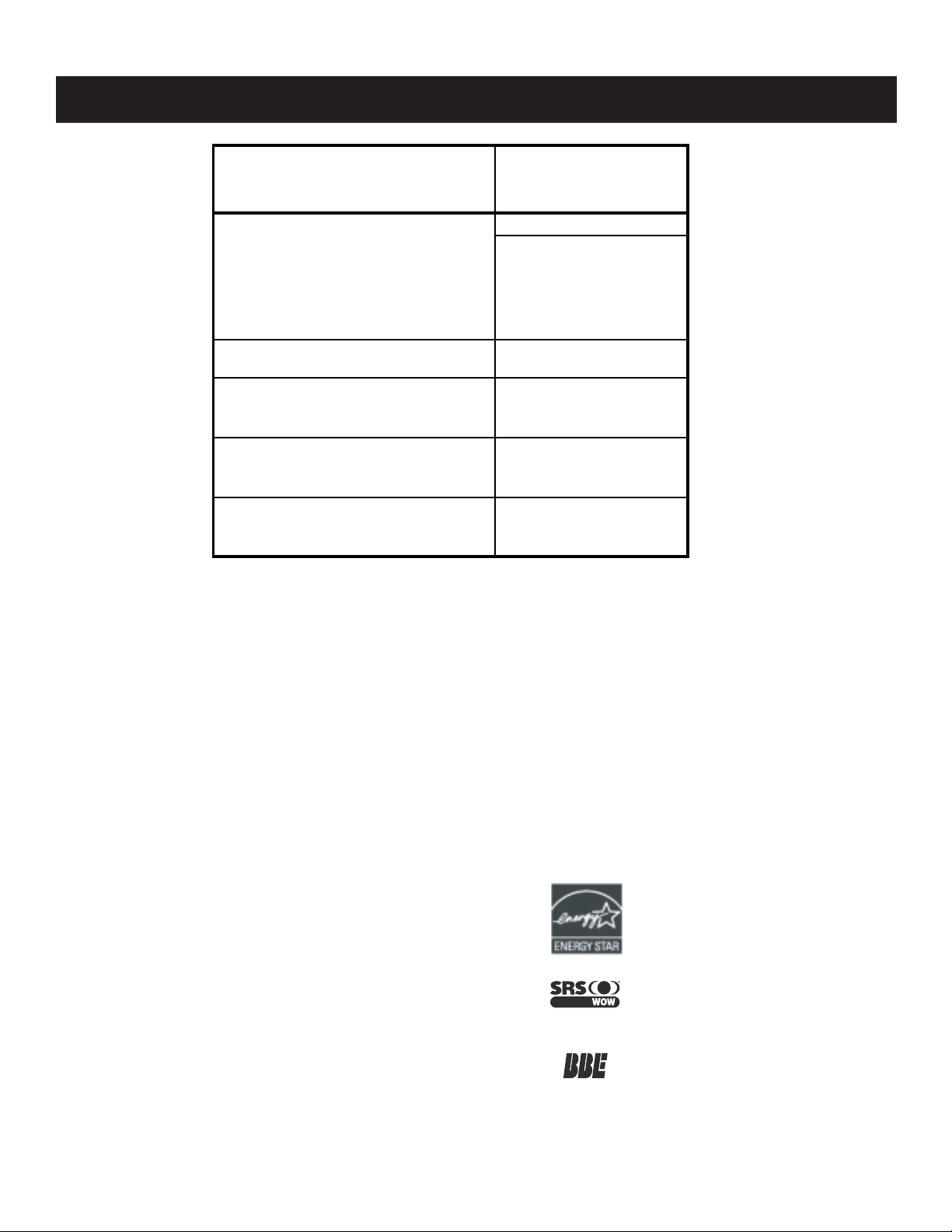
En calidad de compañía asociada a ENERGY
®
, Sony ha determinado que este producto
STAR
cumple con las directrices de uso eficiente de
energía de ENERGY STAR
ENERGY STAR® es una marca registrada de
EEUU.
Fabricado bajo licencia de SRS Labs, Inc. WOW y los
símbolos SRS son marcas regis tradas de SRS Labs,
Inc.
Bajo licencia de BBE Sound, Inc. Licenciado de BBE
Sound, Inc. sobre el numero USP4638258, 5510752 y
5736897. BBE y el símbolo de BBE son marcas
registradas de BBE Sound, Inc.
Sony, WEGA, FD Trinitron, Intelligent Picture y Steady Sound son
marcas comerciales de Corporación Sony.
®
.
Design and specifi cations are subject to change without notice.
KV-21FK120
4

KV-21FK120
WARNINGS AND CAUTIONS
CAUTION
Short circuit the anode of the picture tube and the anode cap to the metal chassis, CRT shield, or carbon painted on the CRT, after
removing the anode.
WARNING!!
An isolation transformer should be used during any service to avoid possible shock hazard, because of live chassis. The chassis of
this receiver is directly connected to the ac power line.
! SAFETY-RELATED COMPONENT WARNING!!
Components identifi ed by shading and ! mark on the schematic diagrams, exploded views, and in the parts list are critical for safe
operation. Replace these components with Sony parts whose part numbers appear as shown in this manual or in supplements
published by Sony. Circuit adjustments that are critical for safe operation are identifi ed in this manual. Follow these procedures
whenever critical components are replaced or improper operation is suspected.
KV-21FK120
5
SAFETY CHECK-OUT
KV-21FK120
After correcting the original service problem, perform the following
safety checks before releasing the set to the customer:
1. Check the area of your repair for unsoldered or poorly soldered
connections. Check the entire board surface for solder splashes and
bridges.
2. Check the interboard wiring to ensure that no wires are “pinched” or
touching high-wattage resistors.
3. Check that all control knobs, shields, covers, ground straps, and
mounting hardware have been replaced. Be absolutely certain that
you have replaced all the insulators.
4. Look for unauthorized replacement parts, particularly transistors,
that were installed during a previous repair. Point them out to the
customer and recommend their replacement.
5. Look for parts which, though functioning, show obvious signs of
deterioration. Point them out to the customer and recommend their
replacement.
6. Check the line cords for cracks and abrasion. Recommend the
replacement of any such line cord to the customer.
7. Check the B+ and HV to see if they are specifi ed values. Make sure
your instruments are accurate; be suspicious of your HV meter if sets
always have low HV.
8. Check the antenna terminals, metal trim, “metallized” knobs, screws,
and all other exposed metal parts for AC leakage. Check leakage as
described below.
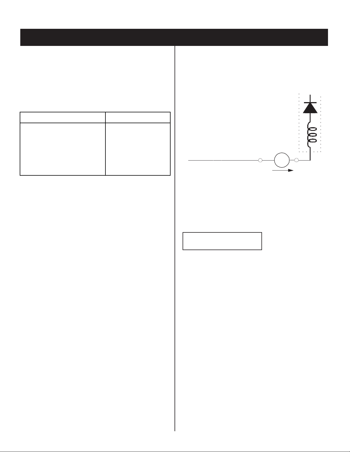
Leakage Test
The AC leakage from any exposed metal part to earth ground and
from all exposed metal parts to any exposed metal part having a
return to chassis, must not exceed 0.5 mA (500 microamperes).
Leakage current can be measured by any one of three methods.
1. A commercial leakage tester, such as the Simpson 229 or RCA
WT-540A. Follow the manufacturers’ instructions to use these
instructions.
2. A battery-operated AC milliampmeter. The Data Precision 245
digital multimeter is suitable for this job.
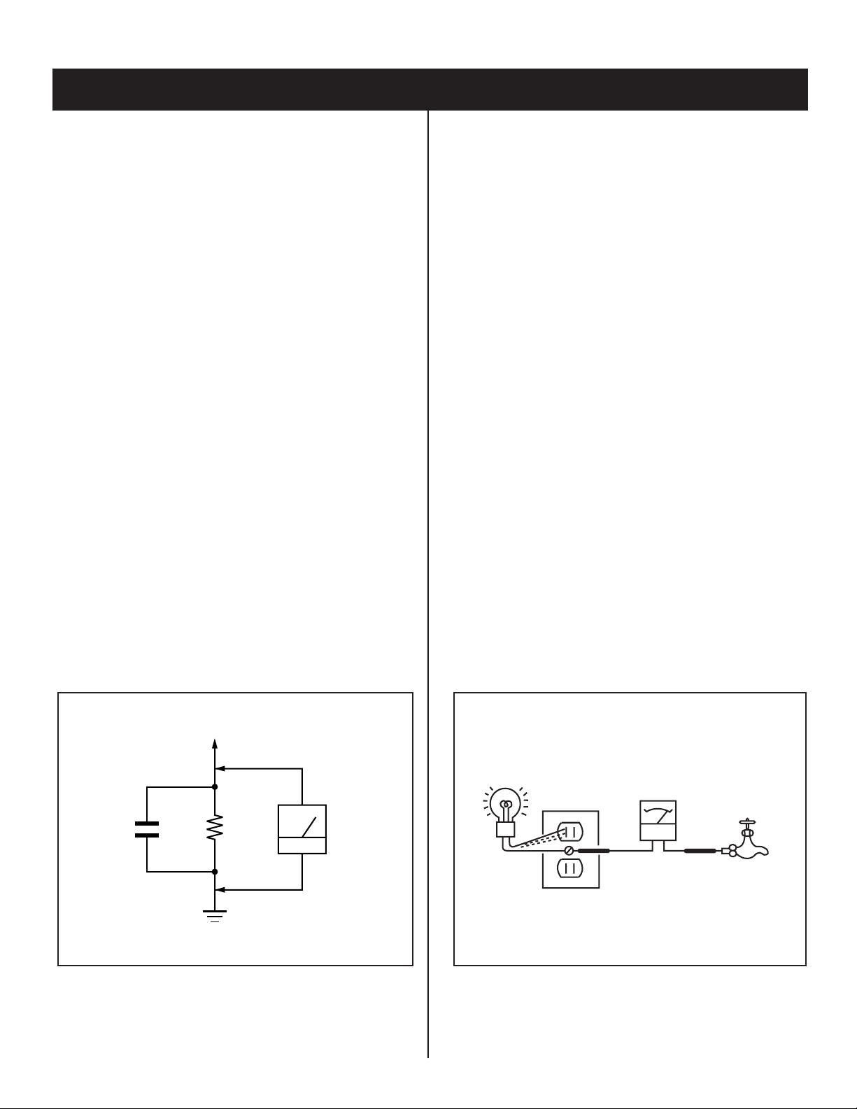
3. Measuring the voltage drop across a resistor by means of a VOM
or battery-operated AC voltmeter. The “limit” indication is 0.75
V, so analog meters must have an accurate low voltage scale.
The Simpson’s 250 and Sanwa SH-63TRD are examples of
passive VOMs that are suitable. Nearly all battery-operated digital
multimeters that have a 2 VAC range are suitable (see Figure A).
How to Find a Good Earth Ground
A cold-water pipe is a guaranteed earth ground; the cover-plate
retaining screw on most AC outlet boxes is also at earth ground. If the
retaining screw is to be used as your earth ground, verify that it is at
ground by measuring the resistance between it and a cold-water pipe
with an ohmmeter. The reading should be zero ohms.
If a cold-water pipe is not accessible, connect a 60- to 100-watt
trouble- light (not a neon lamp) between the hot side of the receptacle
and the retaining screw. Try both slots, if necessary, to locate the hot
side on the line; the lamp should light at normal brilliance if the screw
is at ground potential (see Figure B).
0.15 F
Figure A. Using an AC voltmeter to check AC leakage. Figure B. Checking for earth ground.
KV-21FK120
To Exposed Metal
Parts on Set
1.5 K Ω
Earth Ground
AC
Voltmeter
(0.75 V)
Trouble Light
AC Outlet Box
Ohmmeter
Cold-water Pipe
6
KV-21FK120
SELF-DIAGNOSTIC FUNCTION
Self Diagnosis
Supported model
The units in this manual contain a self-diagnostic function. If an error occurs, the STANDBY/TIMER LED will automatically begin to fl ash. The number
of times the LED fl ashes translates to a probable source of the problem. A defi nition of the STANDBY/TIMER LED fl ash indicators is listed in the
instruction manual for the user’s knowledge and reference. If an error symptom cannot be reproduced, the Remote Commander can be used to review
the failure occurrence data stored in memory to reveal past problems and how often these problems occur.
Diagnostic Test Indicators
When an error occurs, the STANDBY/TIMER LED will fl ash a set number of times to indicate the possible cause of the problem. If there is more than
one error, the LED will identify the fi rst of the problem areas.
Results for all of the following diagnostic items are displayed on screen. No error has occurred if the screen displays a “0”.
Diagnostic Item Descrip-
tion
Power does not turn on
+B overcurrent (OCP)*
I-Prot
IK (AKB)
No. of times
STANDBY/ TIMER
lamp fl ashes
Does not light
2 times
4 times
5 times
Self-Diagnositc
Display/ Diagnos-
tic Result
2:0 or 2:1
4:0 or 4:1
5:0 or 5:1
Probable Cause Location
• Power cord is not plugged in.
• Fuse is burned out (F601). (A Board)
• H.OUT (Q506) is shorted. (A Board)
• RGB Amp (IC1751) is shorted.
(CV Board)
• +13V is not supplied. (A Board)
• IC545 is faulty. (A Board)
• Video OUT (IC545) is faulty.
(A Board)
• IC001 is faulty. (A Board)
• Screen (G2) is improperly adjusted.**
Detected Symptoms
• Power does not come on.
• No power is supplied to the TV.
• AC Power supply is faulty.
• Power does not come on.
• Load on power line is shorted.
• Has entered standby state after horizontal raster.
• Vertical defl ection pulse is stopped.
• Power line is shorted or power supply is stopped.
• No raster is generated.
• CRT Cathode current detection reference pulse
output is small.
*If a +B overcurrent is detected, stoppage of the vertical defl ection is detected simultaneously. The symptom that is diagnosed fi rst by the
mircrocontroller is displayed on the screen.
**Refer to Screen (G2) Adjustments in Section 2-4. of this manual.
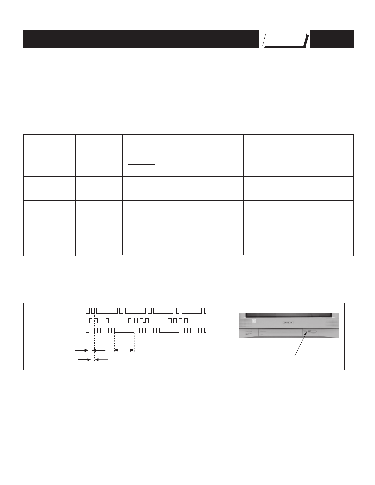
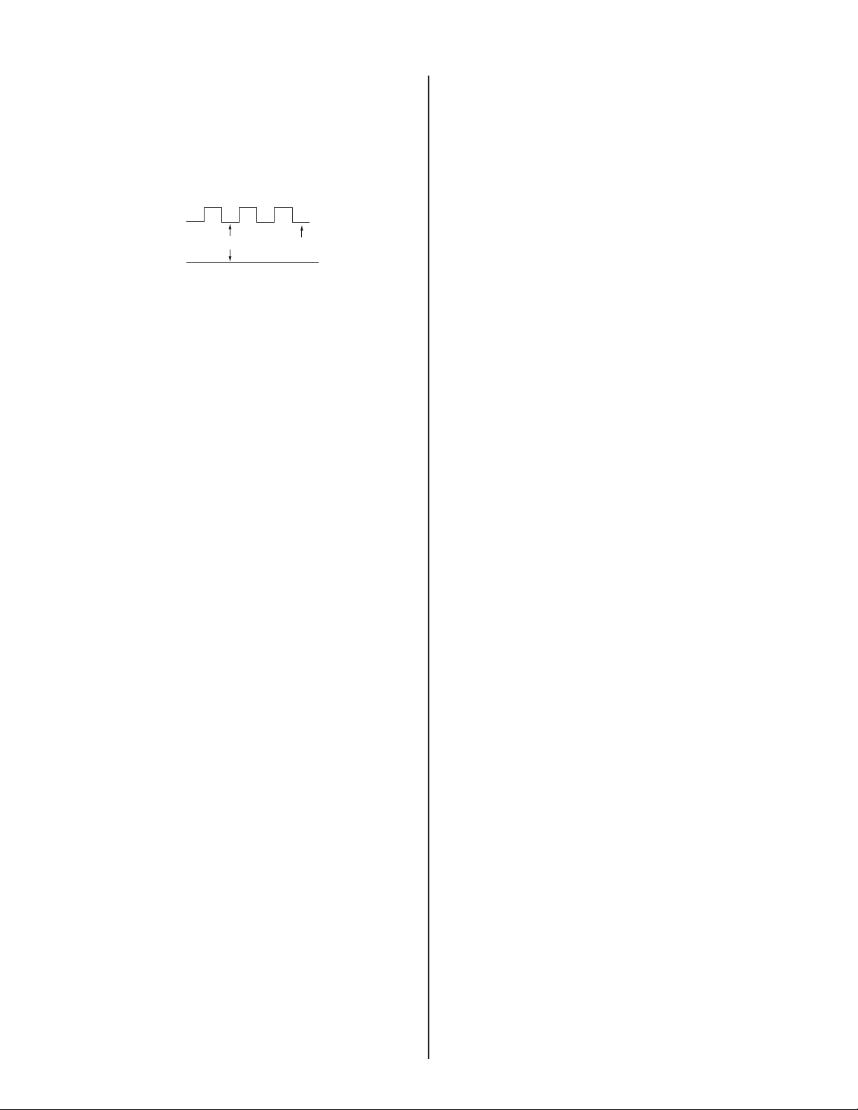
Display of Standby/Timer LED Flash Count
2 times
4 times
5 times
LED ON 0.3 sec.
LED OFF 0.3 sec.
LED OFF
3 sec.
Standby/Timer LED
Diagnostic Item Flash Count*
+B Overcurrent 2 times
I-Prot 4 times
IK (AKB) 5 times
*One fl ash count is not used for self-diagnostic.
Stopping the Standby/Timer LED Flash
Turn off the power switch on the TV main unit or unplug the power cord from the outlet to stop the STANDBY/TIMER LAMP from fl ashing.
KV-21FK120
7
KV-21FK120
Self-Diagnostic Screen Display
For errors with symptoms such as “power sometimes shuts off” or “screen sometimes goes out” that cannot be confi rmed, it is possible to bring up
past occurrences of failure on the screen for confi rmation.
To Bring Up Screen Test
In standby mode, press buttons on the Remote Commander sequentially, in rapid succession, as shown below:
DISPLAY
Self-Diagnostic Screen Display
Handling of Self-Diagnostic Screen Display
Since the diagnostic results displayed on the screen are not automatically cleared, always check the self-diagnostic screen during repairs. When you
have completed the repairs, clear the result display to “0”.
Unless the result display is cleared to “0”, the self-diagnostic function will not be able to detect subsequent faults after completion of the repairs.
Clearing the Result Display
To clear the result display to “0”, press buttons on the Remote Commander sequentially when the diagnostic screen is displayed, as shown below:
Channel 8
Quitting the Self-Diagnostic Screen
To quit the entire self-diagnostic screen, turn off the power switch on the Remote Commander or the main unit.
Channel
SELF DIAGNOSTIC
2: +B OCP 0
3: +B OVP N/A
4: VSTOP 0
5: AKB 1
101: WDT N/A
ENT
5
Sound Volume -
Numeral “0” means that no fault was detected.
Numeral “1” means a fault was detected one time only.
POWER
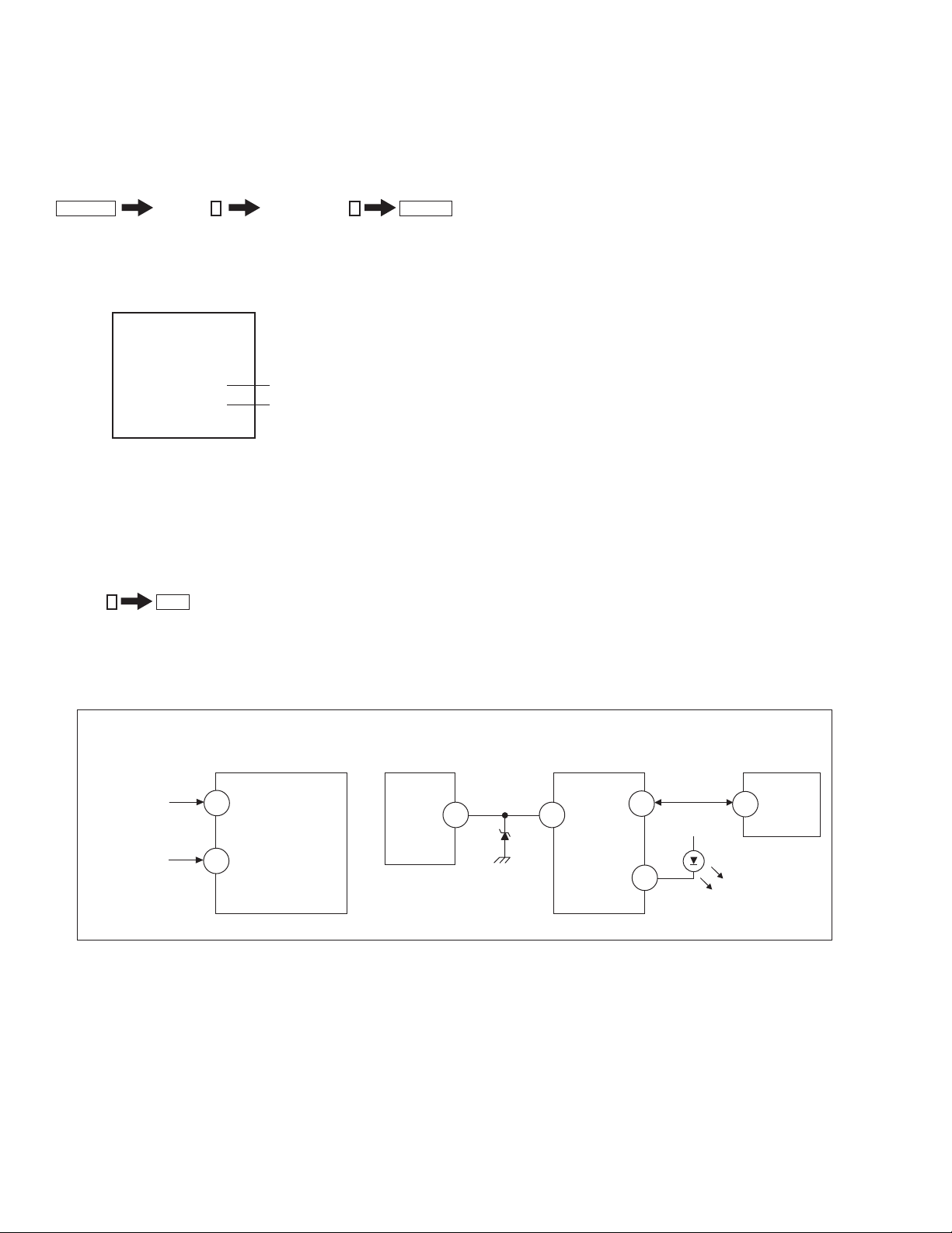
Self-Diagnostic Circuit
FROM
CV BOARD
IC1751 PIN 5
A BOARD
IC001
Y/CHROMA JUNGLE
51
IK-AKBIN
A BOARD
IC545
V. OUT
REF
3
A BOARD
IC001
SYSTEM
IO-BDAT
78
I-Prot
53
A BOARD
IC002
MEMORY
5
BDA
FROM
72
A BOARD
IC561
PIN 7
+B overcurrent (OCP)
Occurs when an overcurrent on the +B (135V) line is detected by pin 72 of IC001 (A Board). If the voltage of pin 72 of IC001 (A Board) is less than 1V
when V.SYNC is more than seven verticals in a period, the unit will automatically turn off.
I-Prot
Occurs when an absence of the vertical defl ection pulse is detected by pin 78 of IC001 (A Board). Power supply will shut down when waveform
interval exceeds 2 seconds.
IK (AKB)
If the RGB levels* do not balance within 2 seconds after the power is turned on, this error will be detected by IC001 (A Board). TV will stay on, but
there will be no picture.
I-HLDWN
O-LED
79
DISPLAY
*(Refers to the RGB levels of the AKB detection Ref pulse that detects 1K).
KV-21FK120
8
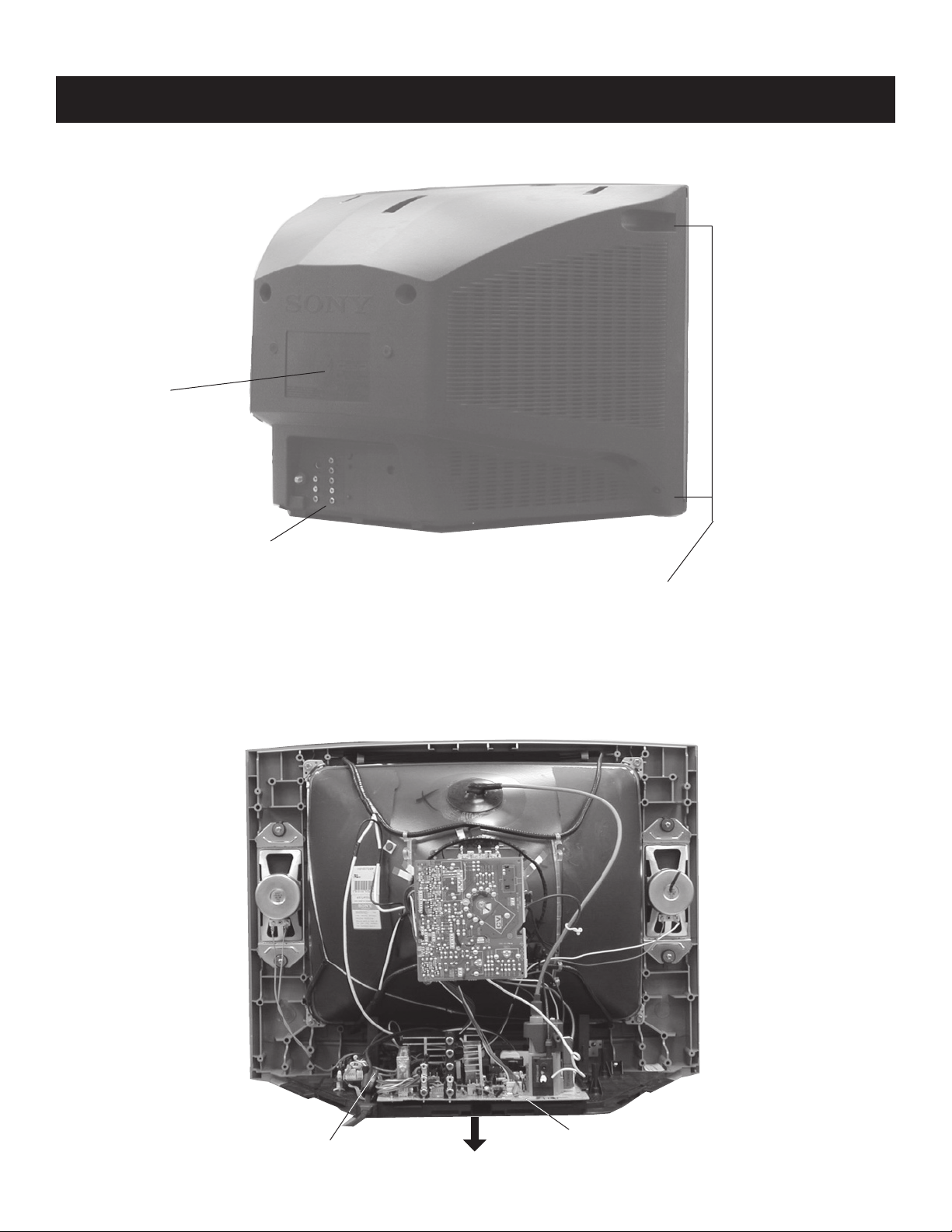
1-1. REAR COVER REMOVAL
Rear Cover
KV-21FK120
SECTION 1: DISASSEMBLY
3 Screws +BVTP 3 x 12
1-2. CHASSIS ASSEMBLY REMOVAL
7 Screws +BVTP 4X16
KV-21FK120
Claw
Chassis Assembly
9
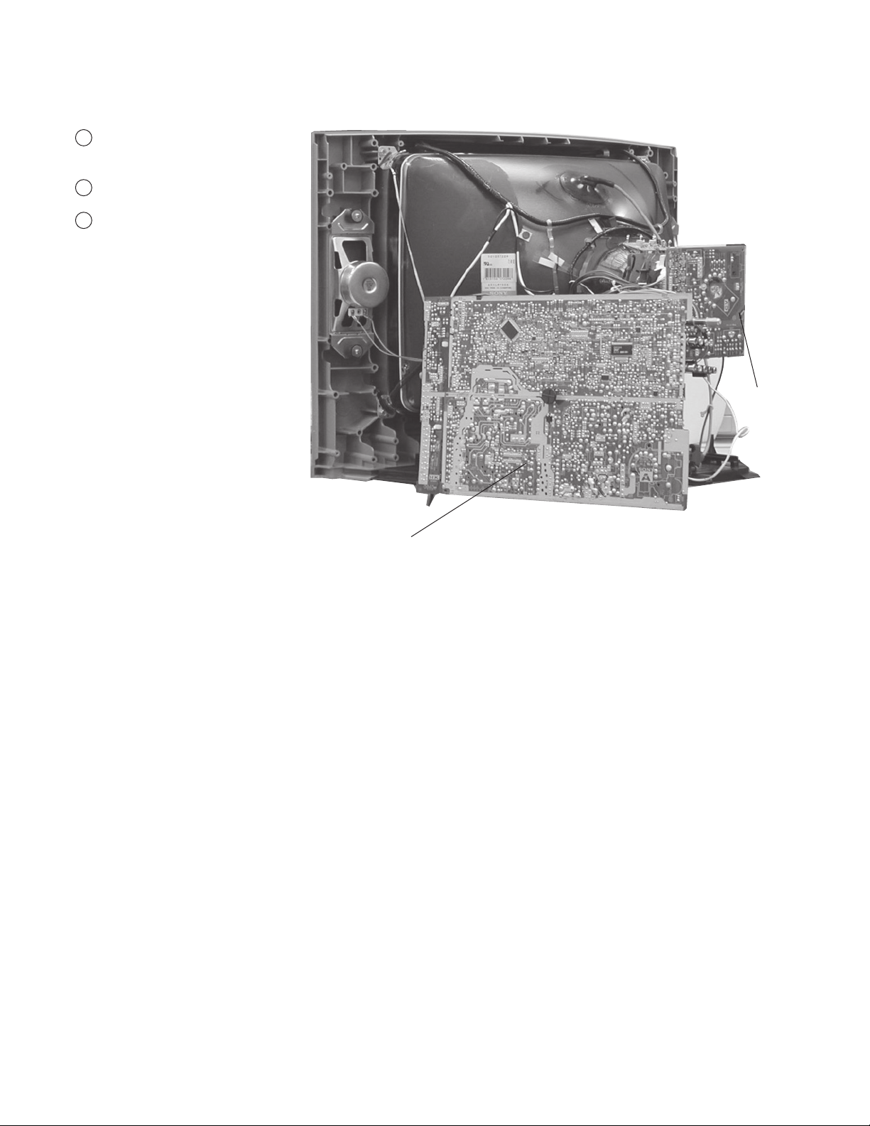
1-3. SERVICE POSITION
1
Depress the PC Board clips to release
KR Board.
2
Disconnect the CN515 cable
Press on catch tab to release A Board
3
and gently pull away from the set.
KV-21FK120
CV Board
A Board
KV-21FK120
10
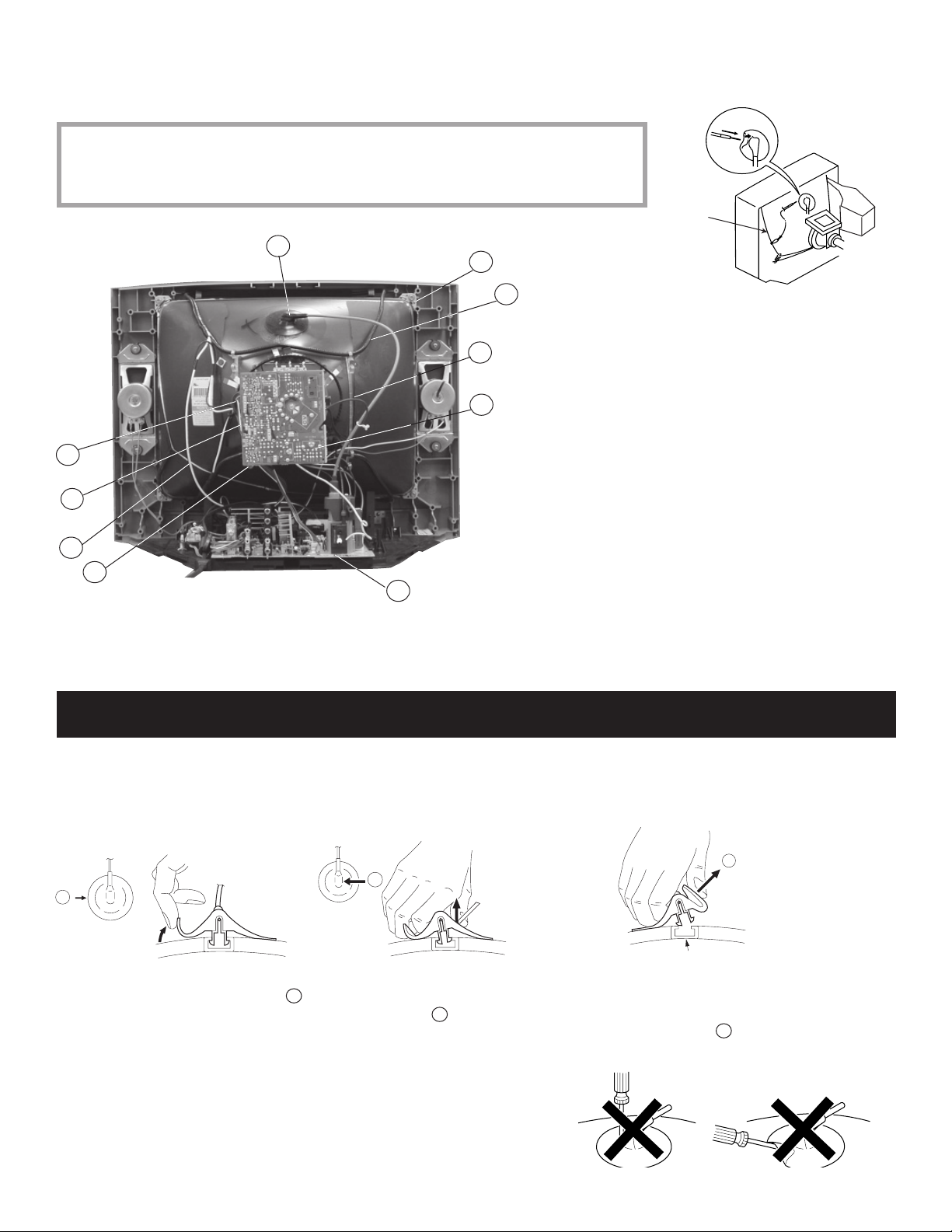
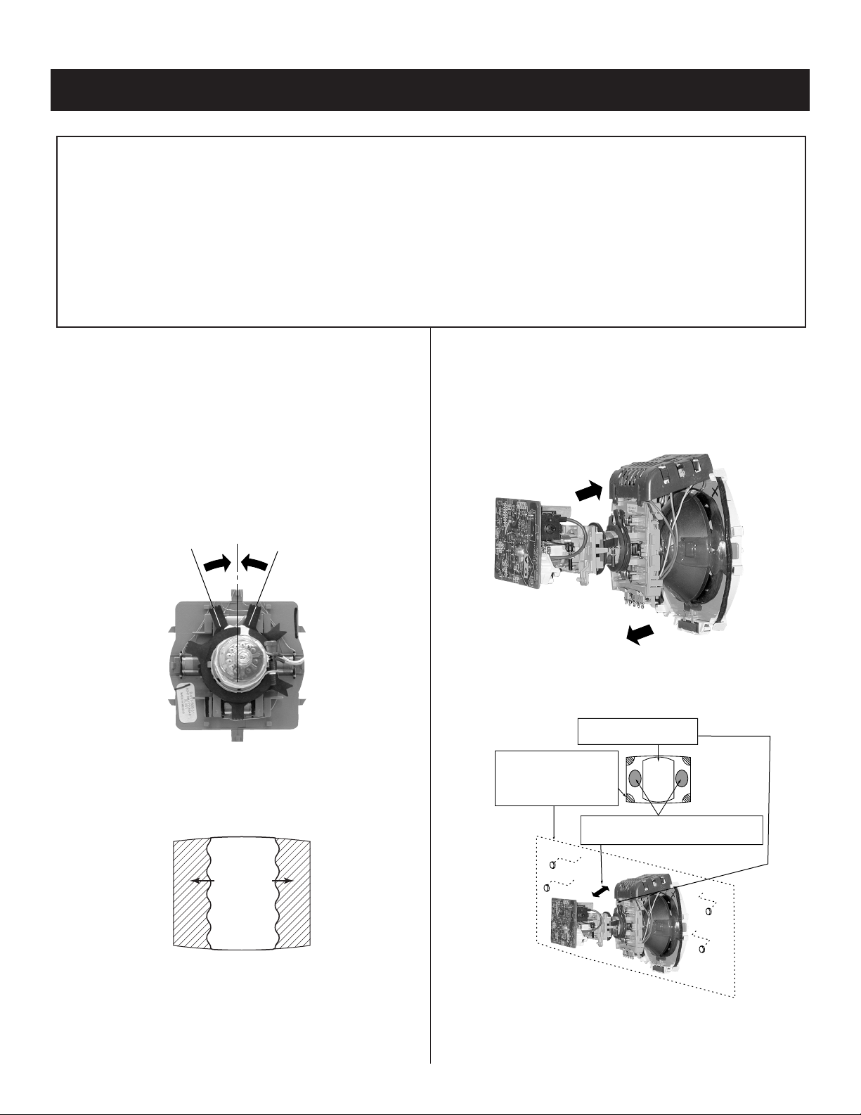
1-4. PICTURE TUBE REMOVAL
WARNING: BEFORE REMOVING THE ANODE CAP
High voltage remains in the CRT even after the power is disconnected. To avoid electric shock,
discharge CRT before attempting to remove the anode cap. Short between anode and CRT
coated earth ground strap.
1
10
8
1. Discharge the anode of the CRT and remove the anode cap.
2. Unplug all interconnecting leads from the defl ection yoke, neck
7
3
6
2
9
5
4
assembly, degaussing coils and CRT grounding strap.
3. Remove the CV Board from the CRT.
4. Remove the chassis assembly.
5. Loosen the neck assembly fi xing screw and remove.
6. Loosen the defl ection yoke fi xing screw and remove.
7. Place the set with the CRT face down on a cushion and remove
the degaussing coil holders.
8. Remove the degaussing coils.
9. Remove the CRT grounding strap and spring tension devices.
10. Unscrew the four CRT fi xing screws [located on each CRT
corner] and remove the CRT
[Take care not to handle the CRT by the neck].
KV-21FK120
Coated
Earth
Ground
Strap
ANODE CAP REMOVAL PROCEDURE
WARNING: High voltage remains in the CRT even after the power is disconnected. To avoid electric shock, discharge CRT before attempting to
remove the anode cap. Short between anode and coated earth ground strap of CRT.
NOTE: After removing the anode cap, short circuit the anode of the picture tube and the anode cap to either the metal chassis, CRT shield, or carbon
painted on the CRT.
REMOVAL PROCEDURES
c
b
a
Anode Button
Turn up one side of the rubber cap in
the direction indicated by arrow a .
HOW TO HANDLE AN ANODE CAP
1. Do not use sharp objects which may cause damage to the surface of the anode
cap.
2. To avoid damaging the anode cap, do not squeeze the rubber covering too
hard. A material fi tting called a shatter-hook terminal is built into the rubber.
3. Do not force turn the foot of the rubber cover. This may cause the shatter-hook
terminal to protrude and damage the rubber.
Use your thumb to pull the rubber
cap fi rmly in the direction indicated
by arrow b .
When one side of the rubber cap separates from
the anode button, the anode cap can be removed
by turning the rubber cap and pulling it in the
direction of arrow c .
KV-21FK120
11
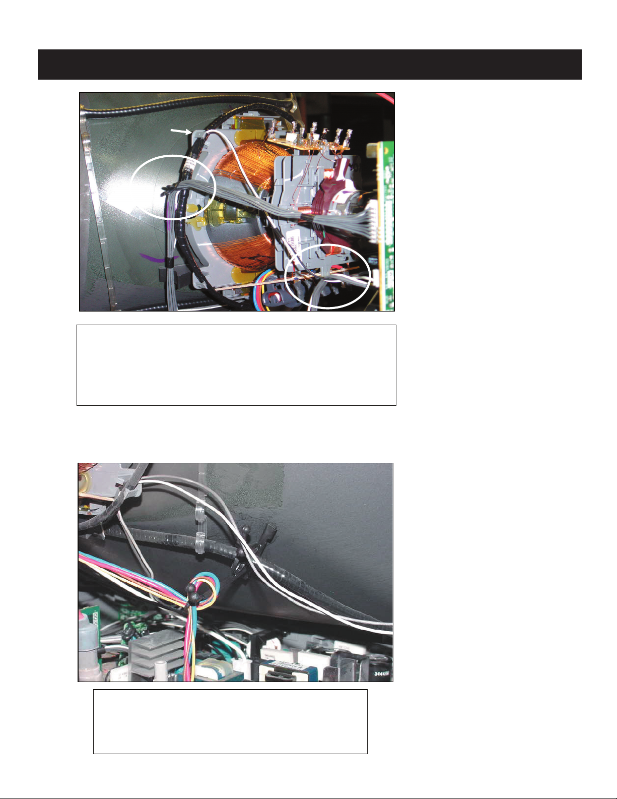
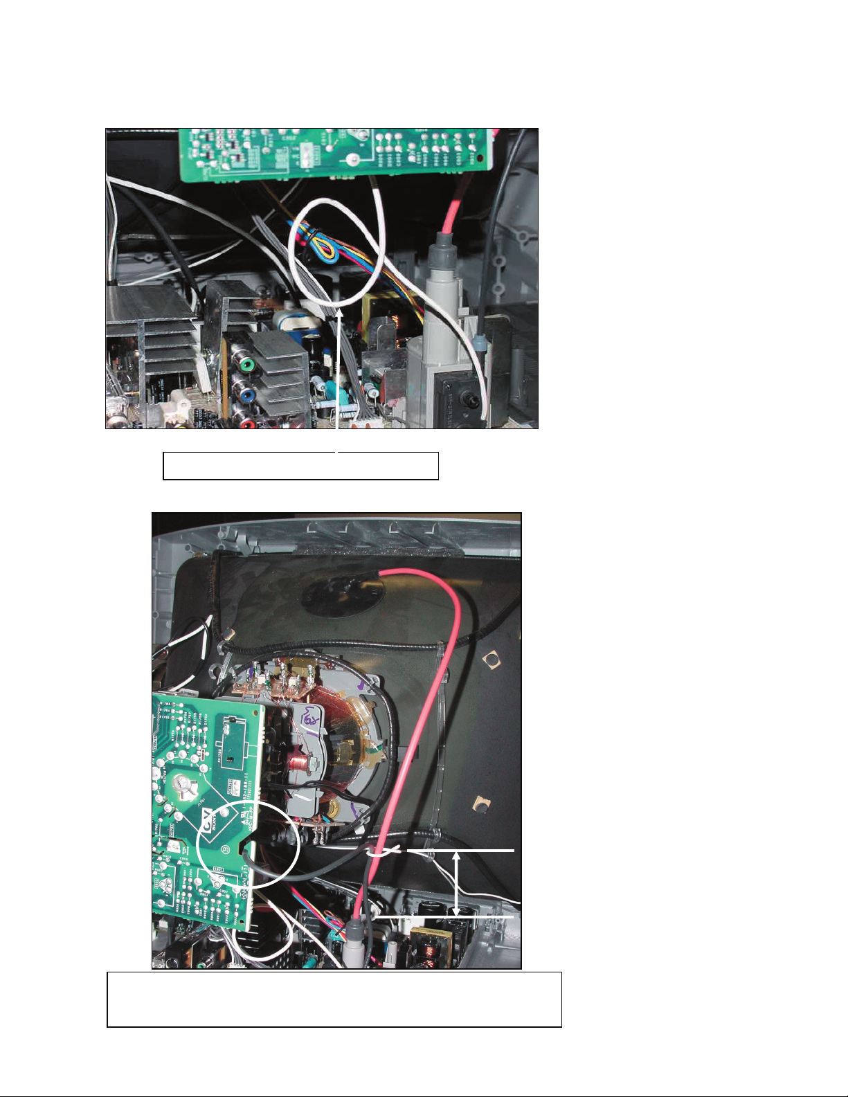
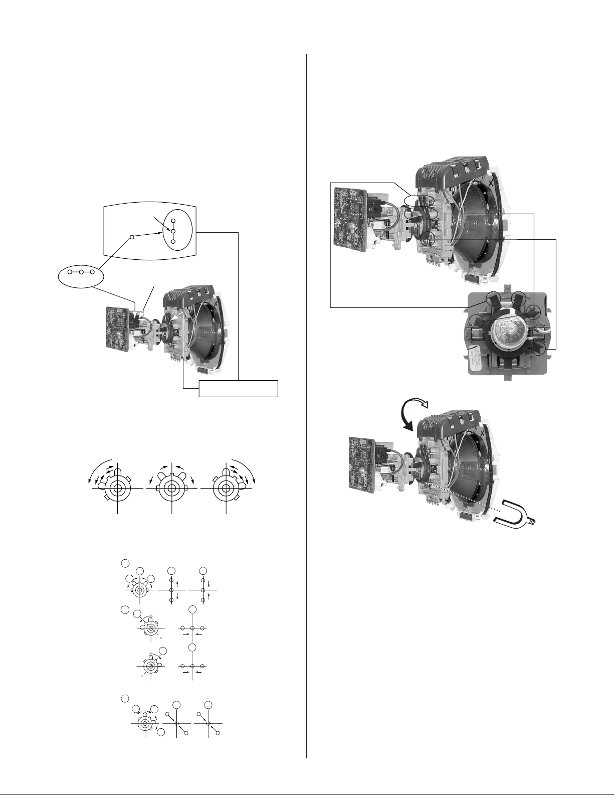
WIRE DRESSINGS
Under clip
KV-21FK120
- Fix RGB harness (A/CN301~CV/CN1752) to rotation
coil using a 9mm purse lock (3-703-982-02).
- Dress heaters harness (A/CN586~CV/CN1751) over
rotation coil's lead wire as shown in picture.
- Install rotation coil lead wire connection under DY clip
KV-21FK120
Dress DY's lead wire using a DGC purse lock (4081-411-02).
Make a loop as shown in picture.
NOTE: Use CRT carbon paint as a reference
12
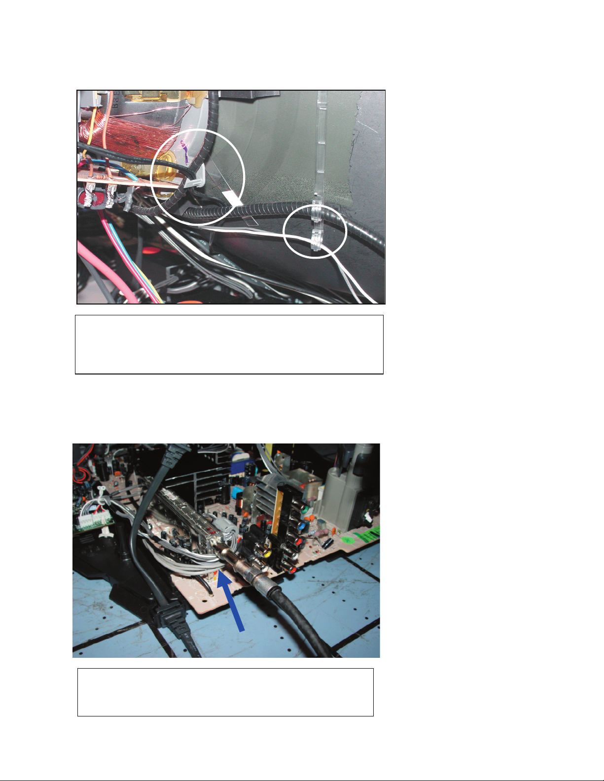
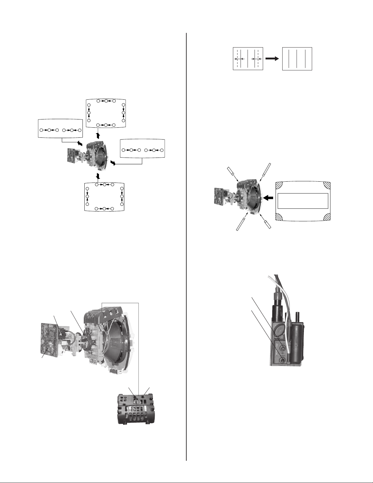
KV-21FK120
Twist G2 wire without stressing it
Dress focus lead and HV cable together using 5mm purse lock
(3-703-981-02), install purse lock 100mm from HV cable's cap.
Dress focus lead through CV board's hook.
KV-21FK120
100mm
13
KV-21FK120
- Dress earth ground wire behind DGC and through
DY's cilp together with rotation coil.
- Dress left speaker wire through DGC band hook (4080-810-22).
- Dress Video harness (A/CN200~A/CN201), 5P
(A/CN402~KR/CN4401), 4P (A/CN403~KR/CN4402) audio
harnesses under tuner's F-Pin.
KV-21FK120
14
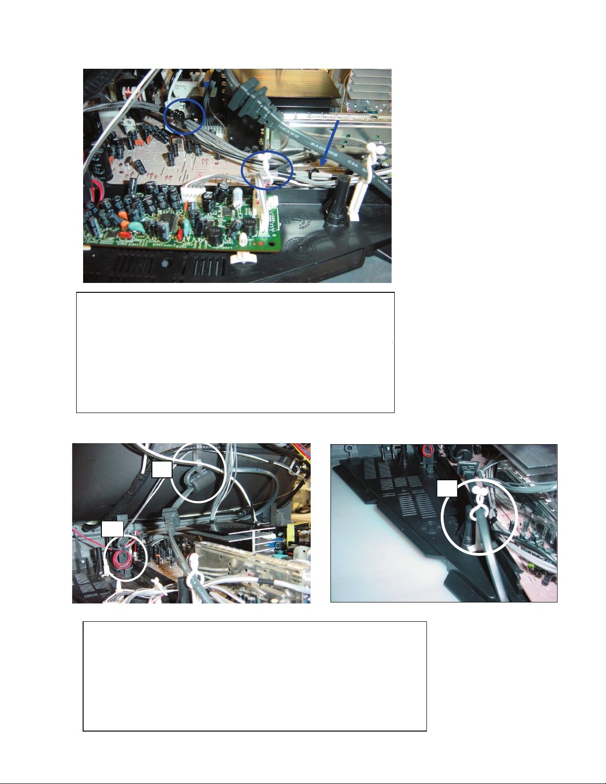
- Dress Video harness (A/CN200~A/CN201) and lightning
-
wire through CLP001.
- Dress Audio harness (HK/CN2402~KR/CN4403) & video
harness (A/CN200~A/CN201) using a 9mm purse lock (3-703
982-02), No lightening wire.
- Dress 5P (A/CN402~KR/CN4401), 4P
(A/CN403~KR/CN4402) & 6P (HK/CN2402~KR/CN4403)
Audio harnesses using a 5mm purse lock (3-703-981-02).
KV-21FK120
2
IMPORTANT: Following operations must be done with A bord on its final
position
1.- Dress Left and right speaker wire into CRT support, red wire with two
loop as shown in picture.
2.- Dress left speaker wire through DGC band(4-080-810-22) upper hook.
Note: This operation must be performed after (1)
Dress AC-Cord and DGC lead wire through DGC band(4-080-810-22)
lower hook.
3.- Dress AC-Cord into bottom board standing purse lock(4-382-296-11).
3
KV-21FK120
15
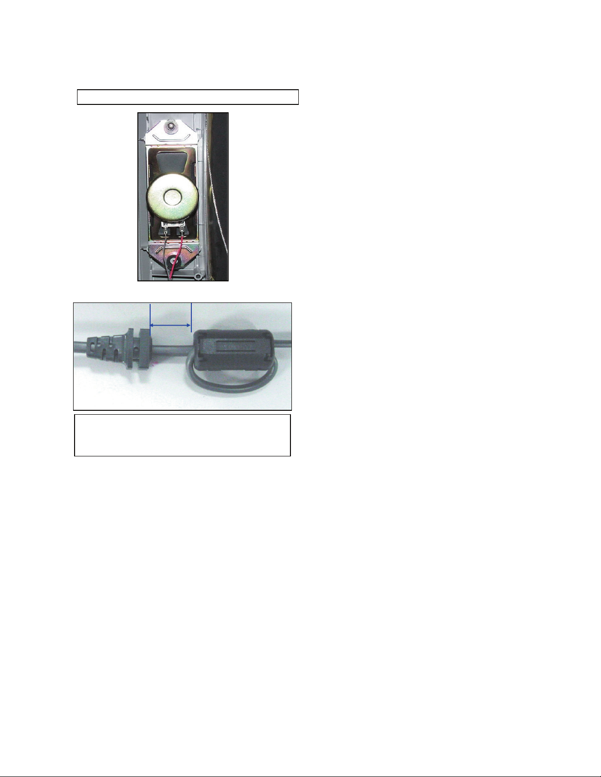
(
Left and Right speakers with terminal on the bottom.
KV-21FK120
20mm
For Chile model
Install Ferrite clamp
1-500-586-11) on Chilean AC-Cord one loop.
KV-21FK120
16
SECTION 2: SET-UP ADJUSTMENTS
KV-21FK120
The following adjustments should be made when a complete
realignment is required or a new picture tube is installed.
These adjustments should be performed with rated power supply
voltage unless otherwise noted.
Set the controls as follows unless otherwise noted:
VIDEO MODE: Pro
PICTURE CONTROL: Normal
BRIGHTNESS CONTROL: Normal
2-1. BEAM LANDING
Before beginning adjustment procedure:
1. Feed in the white pattern signal.
Adjustment Procedure
1. Input a raster signal with the pattern generator.
2. Loosen the defl ection yoke mounting screw, and set the purity control
to the center as shown below:
Purity Control
Perform the adjustments in order as follows:
1. Beam Landing
2. Convergence
3. Focus
4. Screen (G2)
5. White Balance
Note Test Equipment Required:
1. Color Bar Pattern Generator
2. Degausser
3. DC Power Supply
4. Digital Multimeter
6. Switch over the raster signal to red and blue and confi rm the
condition.
7. When the position of the defl ection yoke is determined, tighten it with
the defl ection yoke mounting screw.
8. If landing at the corner is not right, adjust by using the disk magnets.
3. Turn the raster signal of the pattern generator to green.
4. Move the defl ection yoke backward, and adjust with the purity control
so that green is in the center and red and blue are even on both
sides.
Blue Red
Green
5. Move the defl ection yoke forward, and adjust so that the entire
screen becomes green.
KV-21FK120
Purity control
corrects this area.
Disk magnets
or rotatable disk
magnets correct
these areas (a-d).
Deflection yoke positioning
b
d
a
b
c d
corrects these areas.
a
c
17
KV-21FK120
2-2. CONVERGENCE
Before starting convergence adjustments:
1 Perform FOCUS, VLIN and VSIZE adjustments.
2. Set BRIGHTNESS control to minimum.
3. Feed in dot pattern.
Vertical Static Convergence
1. Adjust V. STAT magnet to converge red, green and blue dots in the
center of the screen (Vertical movement adjust S V.STAT RV1750 to
converge).
Center dot
RV1750
R
B
G
V.STAT
R
G
B
Horizontal Static Convergence
If the blue dot does not converge with the red and green dots, peform
the following:
1. Move BMC magnet (a) to correct insuffi cient H.Static convergence.
2. Rotate BMC magnet (b) to correct insuffi cient V.Static convergence.
3. After adjusting the BMC magnet, repeat Beam Landing Adjustment.
V. STAT
BMC MAGNET
PURITY
V.STAT magnet
2. Tilt the V. STAT magnet and adjust static convergence to open or
close the V. STAT magnet.
When the V. STAT magnet is moved in the direction of arrow a and b,
red, green, and blue dots move as shown below:
1
a
b
2
a
a
b
B
G
R
b
b
B
G
R
a
RGB
b
BGR
b
BMC magnet
a
KV-21FK120
3
b
a
a
R
G
b
b
B
G
B
R
18
Dynamic Convergence Adjustment
Before performing this adjustment, perform Horizontal and Vertical
Static Convergence Adjustment.
1. Slightly loosen defl ection yoke screw.
2. Remove defl ection yoke spacers.
3. Move the defl ection yoke for best convergence as
shown below:
B R R B
(R)(B) (B)(R)
KV-21FK120
TLH+
TLH-
G
B
R
R
G
B
BGR
B
G
R
R
R
B
G
R
B
B
G
R
B
G
BGR
B
G
R
G
B
R
G
R
GB
4. Tighten the defl ection yoke screw.
5. Install the defl ection yoke spacers.
TLH Plate Adjustment
1. Input crosshatch pattern.
2. Adjust PICTURE QUALITY to standard, PICTURE and
BRIGHTNESS to 50%, and OTHER to standard.
3 Adjust the Horizontal Convergence of red and blue dots by tilting the
TLH plate on the defl ection yoke.
4. Adjust XCV core to balance X axis.
5. Adjust YCH VR to balance Y axis.
6. Adjust vertical red and blue convergence with V.TILT (TLV VR.)
Note: Perform adjustment 3-6 while tracking items 1 and 2.
Screen-Corner Convergence
1. Affi x a permalloy assembly corresponding to the misconverged areas:
b
a
ba
a-d: screen-corner
misconvergence
c
d
c
d
2-3. FOCUS
1. Adjust FOCUS control for best pictures.
Focus (FV)
RV1750
V.STAT
CV
Board
KV-21FK120
TLH Plate
YCH
Screen (G2)
TLV
19
2-4. SCREEN (G2)
1. Input a dot pattern.
2. Set the PICTURE and BRIGHTNESS controls at minimum and
COLOR control at normal.
3. Adjust SBRT, GCUT, BCUT in service mode with an oscilloscope as
shown below so that voltages on the red, green, and blue cathodes
are 160 ± 2VDC.
±
160 – 2VDC
Ground
4. Observe the screen and adjust SCREEN (G2) VR in FBT to obtain
the faintly visible background of dot signal.
Pedestal
KV-21FK120
KV-21FK120
20
SECTION 3: SAFETY RELATED ADJUSTMENTS
KV-21FK120
3-1. X R565 CONFIRMATION METHOD
(HV HOLD-DOWN CONFIRMATION) AND
READJUSTMENTS
The following adjustments should always be performed when replacing
the following components which are marked with
diagram:
Part Replaced (Y) Adjustment (X)
DY, T585, CRT, IC001, IC561,
IC600, C506, C507, C508, T511,
L510, C588, L588, C566, C561,
C563, D567, D568, D566, PH602,
R567, R568, R565, R566, R562,
R563, R561, R528……....A Board
Y
on the schematic
HV HOLD-DOWN
R565
Preparation Before Confi rmation
1. Using a Variac, apply AC input voltage: 120 ± 2 VAC.
2. Turn the POWER switch ON.
3. Input a white signal and set the PICTURE and BRIGHTNESS
controls to maximum.
4. Confi rm that the voltage between C566 (+) or TP30 and ground is
more than 97 VDC.
Hold-Down Readjustment
If the setting indicated in Step 2 of Hold-Down Operation Confi rmation
cannot be met, readjustment should be performed by altering the
resistance value of R565 component marked with
X
.
T585
FBT
Ammeter
3.0 mA DC
range
ABL
+
-
A
IABL
3-2. B+ VOLTAGE CONFIRMATION AND
ADJUSTMENT
Note: The following adjustments should always be performed when
replacing the following components, which are marked with
schematic diagram on the A Board:
A BOARD:
Y
IC600, PH602
Y
on the
Hold-Down Operation Confi rmation
1. Connect the current meter between Pin 11 of the FBT (T585) and the
PWB land where Pin 11 would normally attach (See Figure 1 on the
next page).
2. Input a dot signal and set PICTURE and BRIGHTNESS to minimum:
IABL = 100 ± 100µA.
3. Confi rm the voltage of A Board TP-23 is 135.6 ± 1VDC.
4. Connect the digital voltmeter and the DC power supply via Diode
1SS119 to C566 (+) and ground (See Figure 1 on next page).
5. Increase the DC power voltage gradually until the picture blanks out.
6. Turn DC power source off immediately.
7. Read the digital voltmeter indication standard < 117.0 VDC.
8. Input a white signal and set PICTURE and BRIGHTNESS to
maximum: IABL = 1350 ± 100µA.
9. Repeat steps 4 through 7.
1. Using a Variac, apply AC input voltage: 130 + 2.0 / - 0.0 VAC.
2. Input a DOT pattern at Q.C.
3. Set the PICTURE and the BRIGHTNESS controls to minimum.
4. Confi rm the voltage of A Board between TP-23 & Ground is =135.6 ±
1VDC.
5. If step 4 is not satisfi ed, replace the components listed above, then
repeat steps 1 through 3.
KV-21FK120
21
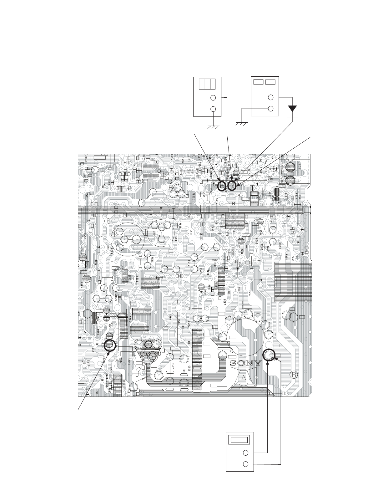
(
)
FIGURE 1
KV-21FK120
DIGITAL
MULTIMETER
+
-
X
R565
R
5
3
1
0
4
S
P
R
5
1
1
J
R
1
R
4
3
7
0
6
R
C
4
5
1
C
5
2
D
5
6
6
5
2
R
5
8
9
T
2
P
4
2
9
L
3
7
0
1
5
6
C
1
5
T
8
2
R
5
3
2
L
3
7
1
1
1
5
C
R
2
1
5
C
1
1
5
L
1
3
1
5
L
C
5
0
2
B
T
2
P
5
R
5
0
4
R
5
3
3
C
5
4
0
5
S
5
6
5
C
I
C
5
3
0
6
2
5
D
5
2
5
L
5
1
0
6
2
5
C
1
5
C
4
1
5
C
2
H
5
Q
B
5
2
5
C
3
L
5
1
5
R
5
3
7
R
5
6
2
2
R
5
2
2
E
C
5
2
7
R
5
4
9
R
5
1
5
6
5
7
C
5
6
1
R
5
4
6
5
D
5
4
6
R
5
4
8
C
5
4
5
R
9
0
R
5
4
0
0
0
D
2
7
C
R
5
4
7
6
1
5
L
R
5
6
C
5
4
8
1
J
R
5
0
POWER
SUPPLY
+
1SS119
C566
Q
4
0
2
R
4
0
8
R
4
1
1
.
H
P
O
R
T
R
5
P
T
3
0
6
6
5
D
R
5
2
9
C
5
6
2
C
5
2
9
1
6
5
C
I
C
5
4
4
2
C
5
9
7
1
T
P
V
.
O
U
T
5
4
7
5
4
5
C
I
4
1
C
5
9
5
P
T
7
1
R
9
0
1
5
1
2
C
2
2
8
D
5
2
8
D
6
1
5
8
3
R
2
8
5
C
P
T
3
3
Q
5
2
1
5
7
5
R
C
5
7
1
R
5
6
8
D
5
6
8
5
6
7
R
5
7
0
D
5
6
R
R
2
8
5
L
9
5
2
6
R
5
6
5
9
7
4
D
6
3
0
6
0
1
2
0
6
C
6
1
0
0
2
4
TP23
8
9
5
E
R
5
0
R
5
9
3
C
5
9
0
E
C
C
6
4
3
0
5
R
1
9
5
R
B
0
9
5
Q
R
5
9
4
T
P
1
3
4
2
6
C
P
3
T
2
1
6
8
0
4
2
6
D
4
5
0
5
C
-
H
O
Q
5
C
5
0
4
1
6
5
0
5
R
U
T
E
0
5
6
0
5
C
6
0
5
D
3
4
R
5
0
6
C
5
1
T
2
P
2
0
C
4
1
5
R
2
1
5
R
H
D
T
5
0
5
T
H
B
5
8
8
R
8
5
L
T
U
O
6
0
5
Q
6
G
2
0
0
V
8
N
/
C
V
D
Y
+
P
T
2
1
V
D
Y
-
T
2
P
7
H
D
Y
-
P
T
2
8
H
D
Y
-
H
D
Y
+
T
P
H
D
Y
+
3
1
H
-
O
2
9
1
5
5
N
C
D
R
5
9
8
T
1
P
9
H
E
A
T
E
R
N
D
5
V
U
T
-
1
3
V
G
N
D
G
N
D
G
N
D
5
5
8
T
+
1
3
V
N
/
C
F
B
T
A
B
L
T
2
P
0
R
5
8
1
AMMETER
3mA dc range
A
+
-
KV-21FK120
22
SECTION 4: CIRCUIT ADJUSTMENTS
Electrical Adjustments by Remote Commander
Use the Remote Commander (RM-Y194) to perform the circuit adjustments in this section.
Test Equipment Required: 1. Pattern generator 2. Frequency counter 3. Digital multimeter 4. Audio oscillator
KV-21FK120
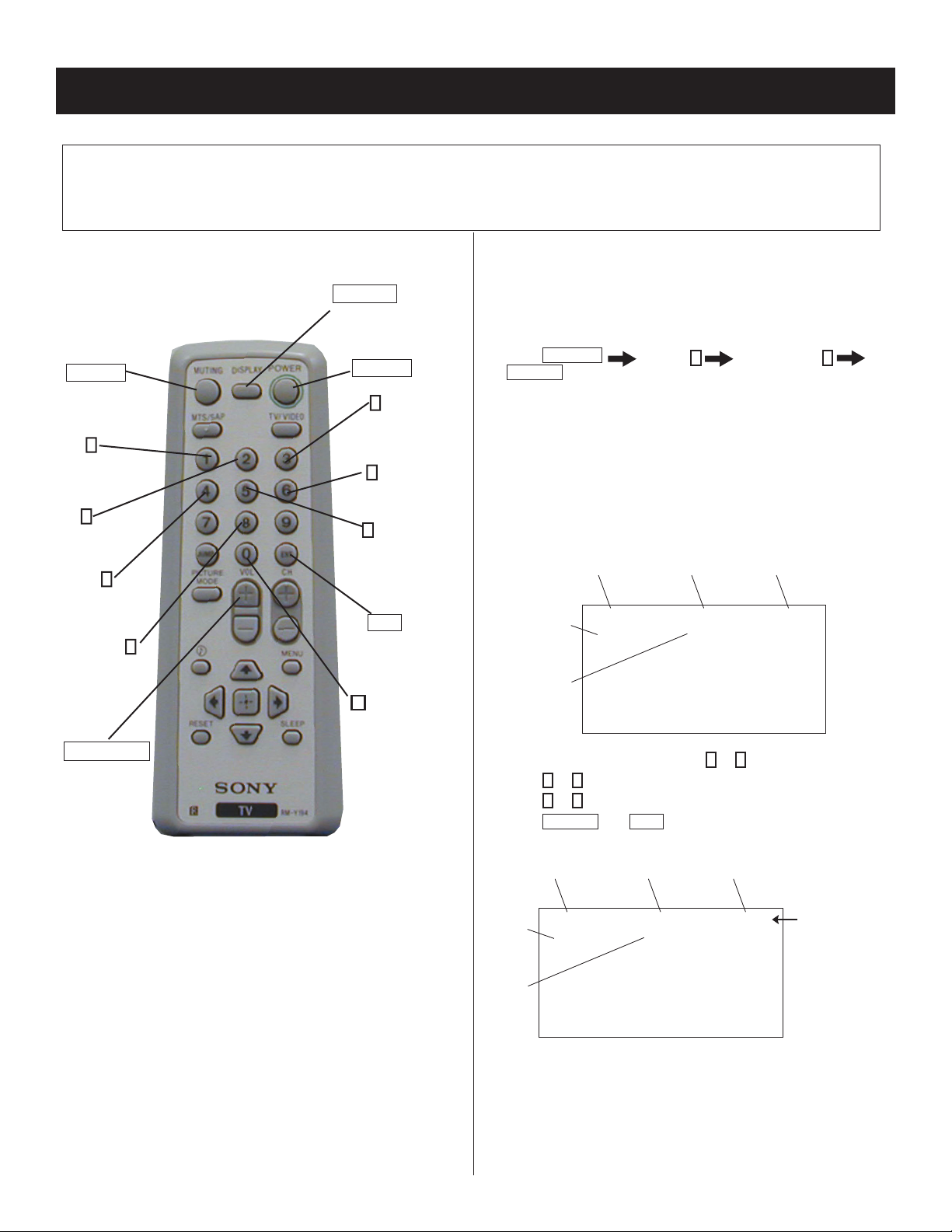
4-1. REMOTE ADJUSTMENT BUTTONS AND
INDICATORS
DISPLAY
(Service Mode)
MUTING
(Enter into
memory)
1
(Display)
Item up
2
(Display)
Category up
4
(Display)
Item down
8
(Initialize)
VOLUME (+)
(Service Mode)
POWER
(Service Mode)
3
(Adjust)
Data up
6
(Adjust)
Data down
5
(Display)
Category
down
ENT
(Enter into
memory)
0
(Remove
from
memory)
4-2. ACCESSING SERVICE ADJUSTMENT
MODE
Service Mode Procedure
1. Standby mode (power off).
2. Press
NOTE: Setting the set in VIDEO mode will make it easier to read the
DISPLAY
POWER
second).
service data.
Channel 5 Sound Volume +
on the Remote Commander (press each button within a
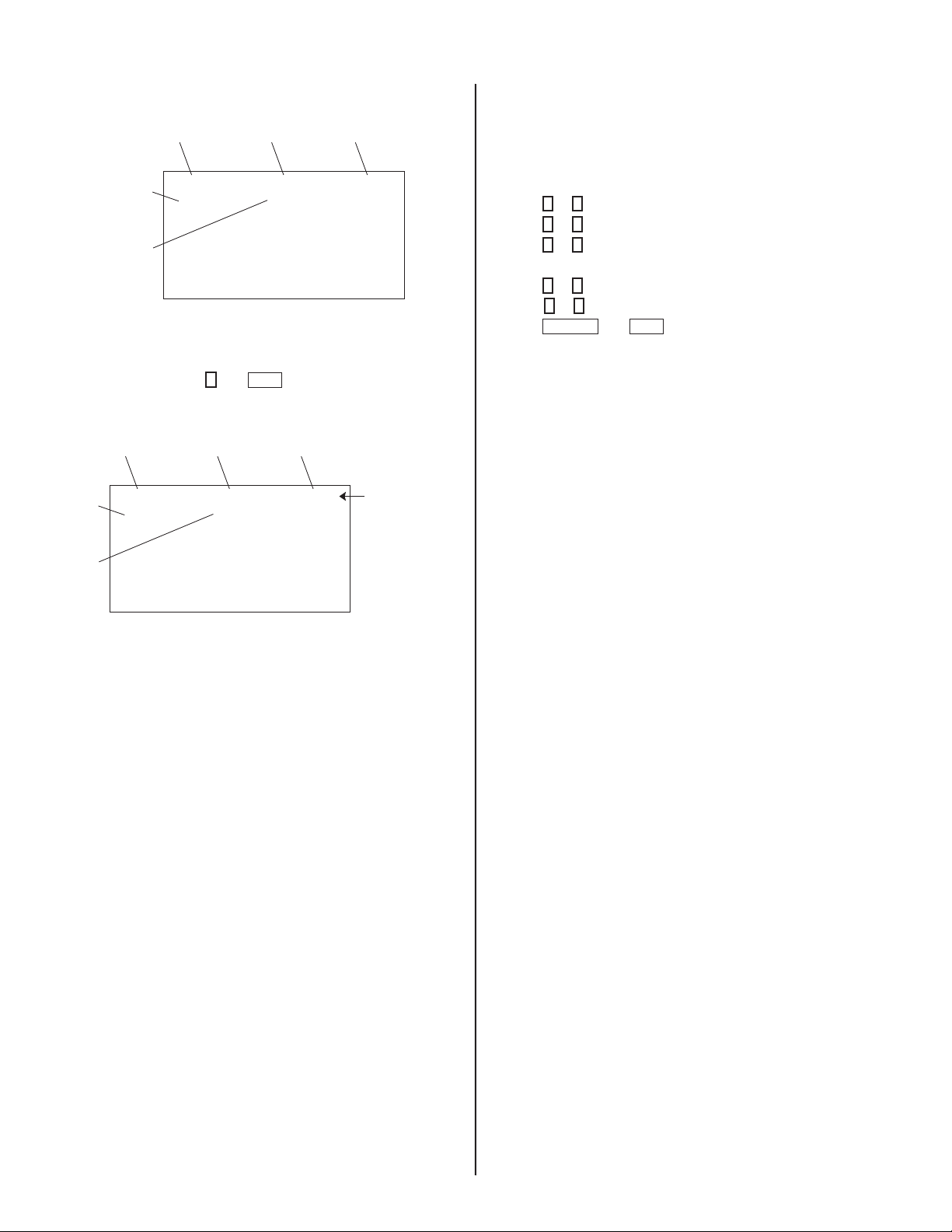
Service Adjustment Mode On
The CRT displays the fi rst Category in the Service list.
Category
Display
Item
Display
Data
1. On the Remote Commander, press 2 or 5 to select the Category.
2. Press 1 or 4 to select the Item.
3. Press 3 or 6 to change the Data.
4. Press
MUTING
HSIZ 1 : 51 NVM:OK
M655E2AMF-107FP
then
Signal
Type
NTSC VIDEO1DEF
ENT
to write into the memory.
Channel
Type
S 3.OD
KV-21FK120
RM-Y194
Display
Item
Display
Data
Category
HSIZ 1 : 51
M655E2AMF-107FP
Signal
Type
NTSC WRITEDEF
Channel
Type
Text changes
to “WRITE”
and changes
from green to red
S 3.OD
23
KV-21FK120
Service Adjustment Mode Memory
Signal
Type
NTSC VIDEO1DEF
Display
Item
Display
Data
Category
HSIZ 1 : 51 NVM:OK
M655E2AMF-107FP
Carry out Step 1 when adjusting IDs 0-6 and when replacing and
adjusting IC002.
1. In Service Mode, press 8 then
ENT
on the Remote Commander to
re-initialize.
Display
Item
Display
Data
Category
HSIZ 1 : 51
M655E2AMF-107FP
Signal
Type
NTSC RESETDEF
Channel
Type
S 3.OD
Channel
Type
S 3.OD
Text changes
to “RESET”
and changes
from green to red
4-3. WHITE BALANCE ADJUSTMENTS
1. Input an entire white signal with burst.
2. Access Service Adjustment Mode.
3. Set the PICTURE and BRIGHTNESS to minimum.
4. Adjust with SBRT if necessary.
5. Press 2 or 5 to select the VP1 Category
6. Press 1 or 4 to select GCUT and BCUT.
7. Press 3 or 6 to adjust the data value for best white balance.
8. Set the PICTURE and BRIGHTNESS to maximum.
9. Press 1 or 4 to select GDRV and BDRV.
10. Press 3 or 6 to adjust the data value for best white balance.
11. Press
MUTING
then
ENT
to write into the memory.
4-4. MEMORY WRITE CONFIRMATION
METHOD
1. After adjustment, pull out the plug from the AC outlet, then replace
the plug in the AC outlet again.
2. Turn the power switch ON and set to Service Mode.
3. Call the adjusted items again to confi rm they were adjusted.
2. The set automatically turns off after re-initializing is complete.
KV-21FK120
24
4-5. SERVICE DATA LIST
K
K
K
K
K
K
KV-21FK120
Service
Group
DEF
No. Name
1H-SIZE HSIZ
2 H-AFC-2 phase HPOS
3 VSIZE VSIZ
4 VPOSI VPOS
5LINI VLIN
6 S CORRECTION SCOR
7BOW VBOW
8 ANGLE VANG
9 TRAPESIUM TRAP
10 PARABOLA PAMP
11 UPPER CORNER UPIN
12 LOWER CORNER LPIN
13 (TROT) TROT
14 FBPBL
15 HBLK R POS RBL
16 HBLK F POS LBL
17 VBLK POS VBL
18 Macro OFF HMS
19 HOUT DUTY HDW
20 H AFC Gain AFC
21 H Charge pump AFC1
22 AFC1 PULLIN AFCW
23 V CD MODE CDMD
24 SYNC SLICE LVL(H) HSS
25 SYNC SLICE LVL(L) VSS
26 AUTO SLICE DOWN SLDN
27 AUTO SLICE UP SLUP
28 VJPSW JPSW
29 HVCO FREERUN OFFSET HOSC
30 EHT EHT
31 EHT GAIN EHTG
OSD Description
HBL
H SIZE(EW DC) : YUV OFFSET
H POSITION : YUV OFFSET
V RAMP SIZE : YUV OFFSET
V POSITION(RAMP DC) not useful : YUV OFFSET
V LINEARITY
S CORRECTION
BOW
ANGLE
EW TRAPESIUM
EW PIN
UPPER PIN
LOWER PIN
TROT
H BLK mode select
HBLK rear timing : YUV OFFSET
HBLK front timing : YUV OFFSET
V BLK width
TOP VEND(when MACROVISION) prevent OFF
H PULSE WIDTH(25u/19u)
AFC GAIN
AFC1 TIME CONSTANT
AFC1 PULL IN WIDE
V DET WINDOW SW TIMING
SYNC SLICE LEVEL(H sepa)
SYNC SLICE LEVEL(V sepa)
Auto Slice level DOWN
Auto Slice level UP
Jump SW
H VCO fo offset ADJUST OFFSET
EHT
EHT MODE
Initial Data
(DEC)
41
31
31
35
28
45
36
44
29
47
31
29
109
00
09
35
00
00
01
00
03
00
01
00
03
00
00
00
07
04
01
KV-21FK120
25
KV-21FK120
Service
Group
16:09VP1
No. Name OSD
1 VSIZE VSIZ
2 VPOSI VPOS
3LINI VLIN
4 S CORRECTION SCOR
5 TRAPESIUM TRAP
6 PARABOLA PAMP
7 UPPER CORNER UPIN
8 LOWER CORNER LPIN
9 ABL GAIN ABLG
10 CONT SCON
11 VJP WIDTH VPW
1 Drive R RDRV
2 Drive G GDRV
3 Drive B BDRV
4 R CMP H/L RCUT
5 G CMP H/L GCUT
6 B CMP H/L BCUT
7CONT SCON
8 TINT SHUE
9 COLOR SCOL
10 BRIGHT SBRT
11 R Output Mute RON
12 G Output Mute GON
13 B Output Mute BON
14 BLUE STRETCH BLLV
15 RGB MTX MTRX
16 RRAY AXIS
17 SHARP OVER SSHO
18 SHARP PRE SSHP
19 APERTURE FREQUENCY SHPF
20 SHARP NOISE CORING LV SHCL
21 SHARPNESS MAX GAIN SHMX
22 ACL G ACLV
23 AKBD AKBD
24 AKB SW AKBS
25 AKB REFPLS POS REFP
26 YNR NOISE CORING LV YNRC
27 BLACK STRETCH SW BKON
28 BLACK STRETCH TIME1 BKAT
29 BLACK STRETCH TIME2 BKRC
30 BLACK STRETCH DEPTH BKDP
31 BLKSTPNT BKSP
Description
V RAMP SIZE
V POSITION(RAMP DC)
V LINEARITY
S CORRECTION
EW TRAPESIUM
EW PIN
UPPER PIN
LOWER PIN
ABL GAIN
SUB CONTRAST LEVEL
Jump Pulse Width
R DRIVE
G DRIVE : GDOF offset (only Color Temp. "Warm")
B DRIVE : BDOF offset (only Color Temp. "Warm")
Hardware AKB(R) CMP DATA
Hardware AKB(G) CMP DATA :
GCOF offset (only Color Temp. "Warm")
Hardware AKB(B) CMP DATA :
BCOF offset (only Color Temp. "Warm")
SUB CONTRAST LEVEL
SUB TINT(HUE) YUV/notYUV
SUB COLOR LEVEL YUV/notYUV
SUB BRIGHTNESS YUV/notYUV
R OUTPUT ON ( 0:R Output OFF 1:R Output ON )
G OUTPUT ON ( 0:G Output OFF 1:G Output ON )
B OUTPUT ON ( 0:B Output OFF 1:B Output ON )
BLUE STRETCH(00:no <-> 11:deep)
only Color Temp. "Cool"
MATRIX RATIO SELECT
R-Y PHASE OFFSET
SUB SHARPNESS GAIN(OVER) RF/VIDEO/YUV
SUB SHARPNESS GAIN(PRE) RF/VIDEO/YUV
SHRPNESS fo(00:2 CLK <-> 11:5 CLK) RF/VIDEO/YUV
SHARPNESS CORING LEVEL
SHARPNESS LIMITTER LEVEL
ACL GAIN
AKB Self Diagnostic Counter(@1sec)
AKB Switch ( 0 : AKB OFF 1 : H/W AKB ON )
AKB REFPLS timing
YNR LIMITER LEVEL
BLACK STRETCH ON
BLACK STRETCH DETECTOR TIME CONSTANT1
BLACK STRETCH DETECTOR TIME CONSTANT2
BLACK STRETCH START POINT
BLACK STRETCH POINT RF/notRF
Initial Data
(DEC)
55
37
37
9
30
25
32
31
15
10
00
64/64
45/47
59/62
120/120
68/67
51/49
23
10/10
16/16
16/16
01
01
01
01
00
52
10/25/25
15/30/30
01/00/00
00
15
00
02
01
00
15
01
15
04
03
02/02
KV-21FK120
26
KV-21FK120
Service
Group
VP2NR
No. Name OSD Description
1 VM GAIN(Off) VMOF
2 VM GAIN(Low) VMLO
3 VM GAIN(High) VMHI
4VM DELAY VMDL
5 VM POL VMPL
6VM WIDTH VMWD
7 VM CORING LEVEL VMCL
8 VM MAX VMMX
9 KILLER LEVEL CKLV
10 FORCE KILLER CKON
11 ALFA ALFA
12 MANEXP YCMD
13 V APERTURE CORING LV VACL
14 V APERTURE GAIN VAGA
15 V APERTURE MAX GAIN VAMX
16 GAMMA GAMM
17 Y DELAY YDLY
18 C DELAY CDLY
19 Y Mute YOFF
20 SAW FILTER(7.2MHzBPF) CBPF
21 BGP POS BGPP
22 G DRIVE OFFSET GDOF
23 B DRIVE OFFSET BDOF
24 GCUT OFFSET GCOF
25 BCUT OFFSET BCOF
26 DCTRAN VTH<6:0> DCTV
27 DCTRAN GAIN<4:0> DCTG
VM LEVEL at "Off" Setting
VM LEVEL at "Low" Setting
VM LEVEL at "High" Setting
VM DELAY
VM PORALITY
VM WIDTH
VM CORING LEVEL
VM LIMITER LEVEL
COLOR KILLER VTH YUV/notYUV
FORCE KILLER
ADAPTIVE DET SENSITIVITY
YC SEPA FORCE SELECT
(00:ADAPTIVE 01:H 10:V 11:HV)
V APERTURE CORING LEVEL
V APERTURE GAIN LEVEL
V APERTURE LIMITER LEVEL
GAMMA(00:no <-->11:deep)
Y DELAY TIME YUV/notYUV
C DELAY
Y OUTPUT MUTE
C BPF fo HI
BGP(for C DECODER)TIMING YUV/notYUV
G DRIVE OFFSET only Color Temp. "Warm"
B DRIVE OFFSET only Color Temp. "Warm"
GCUT CMP DATA OFFSET only Color Temp. "Warm"
BCUT CMP DATA OFFSET only Color Temp. "Warm"
DCTRANSFER VTH
DCTRANSFER GAIN
Initial Data
(DEC)
02
04
08
06
00
00
00
15
01/00
00
02
00
00
05
05
01
01/03
00
00
00
09/28
09
14
11
28
30
15
KV-21FK120
1 COLOR SCOL
2 SHARP NOISE CORING LV SHCL
3 SHARPNESS MAX GAIN SHMX
4 YNR NOISE CORING LV YNRC
5 VM GAIN(High) VMHI
6 VM CORING LEVEL VMCL
7 VM MAX VMMX
8 V APERTURE MAX GAIN VAMX
9 GAMMA GAMM
10 YNR SW YNRS
11 WEAK_SIG_VTH WSTH
12 WEAK SIG VIDEO ATT WSVA
13 WEAK SIG CHROMA ATT WSCA
14 THRNZV1 NRCH
15 THRNZV2 NRCL
16 THRNZH1 NRVL
17 THRNZH2 NRVH
18 NR COUNTER IPNC
19 NR Vsync Counter IPNV
SUB COLOR LEVEL
SHARPNESS CORING LEVEL
SHARPNESS LIMITTER LEVEL
YNR LIMITER LEVEL
VM LEVEL at "High" Setting
VM CORING LEVEL
VM LIMITER LEVEL
V APERTURE LIMITER LEVEL
GAMMA(00:no <-->11:deep)
YNR ON
WEAK_SIGNAL VTH
WEAK SIGNAL VIDEO ATT
WEAK SIGNAL CHROMA ATT
NOISE DET TIME CONSTANT
NOISE DET TIME CONSTANT
NOISE DET VTH
NOISE DET VTH
Intelligent Picture "DETNZ" Counter
Intelligent Picture "DETNZ" Counter
16
15
07
07
10
00
07
00
00
01
07
00
05
00
16
02
00
02
10
27
Use the Remote Commander to select the PICTURE MODE (Vivid, Standard, Movie, or Pro) you want to adjust.
KV-21FK120
Service
Group
PALLET for VIVIDPALLET for STDPALLET for MOVIE
Service
Group
No.
1 PICTURE VPIC
2 BRIGHTNESS VBRI
3 COLOR VCOL
4 HUE VHUE
5 SHARPNESS VSHA
6 VM VVM
7 COLOR TEMP VTRI
8 APERTURE G VAPA
9 GAMMA VGMA
10 DCT LV VDCT
11 BLACK STRETCH DEPTH VBKP
12 BLACK STRETCH DEPTH TBKD
Name OSD Description
Picture(VIVID)
Brightness(VIVID)
Color(VIVID)
Hue(VIVID)
Sharpness(VIVID)
VM(VIVID)
Color Temp(VIVID)
Aperture G(VIVID)
Gamma(VIVID)
DCT LV(VIVID)
BLACK STRETCH DEPTH(VIVID) for VIDEO INPUT
BLACK STRETCH DEPTH(VIVID) for TUNER INPUT
No. Name OSD Description
1 PICTURE VPIC
2 BRIGHTNESS VBRI
3 COLOR VCOL
4HUE VHUE
5 SHARPNESS VSHA
6 VM VVM
7 COLOR TEMP VTRI
8 APERTURE G VAPA
9 GAMMA VGMA
10 DCT LV VDCT
11 BLACK STRETCH DEPTH VBKP
12 BLACK STRETCH DEPTH TBKD
Picture(STANDARD)
Brightness(STANDARD)
Color(STANDARD)
Hue(STANDARD)
Sharpness(STANDARD)
VM(STANDARD)
Color Temp(STANDARD)
Aperture G(STANDARD)
Gamma(STANDARD)
DCT LV(STANDARD)
BLACK STRETCH DEPTH(STD) for VIDEO INPUT
BLACK STRETCH DEPTH(STD) for TUNER INPUT
Initial Data
(DEC)
63
27
37
31
31
02
00
05
03
23
03
03
Initial Data
(DEC)
50
30
32
31
32
01
01
05
01
15
03
03
Service
Group
KV-21FK120
No. Name
OSD Description
1 PICTURE VPIC
2 BRIGHTNESS VBRI
3 COLOR VCOL
4 HUE VHUE
5 SHARPNESS VSHA
6 VM VVM
7 COLOR TEMP VTRI
8 APERTURE G VAPA
9 GAMMA VGMA
10 DCT LV VDCT
11 BLACK STRETCH DEPTH VBKP
12 BLACK STRETCH DEPTH TBKD
Picture(MOVIE)
Brightness(MOVIE)
Color(MOVIE)
Hue(MOVIE)
Sharpness(MOVIE)
VM(MOVIE)
Color Temp(MOVIE)
Aperture G(MOVIE)
Gamma(MOVIE)
DCT LV(MOVIE)
BLACK STRETCH DEPTH(MOVIE) for VIDEO INPUT
BLACK STRETCH DEPTH(MOVIE) for TUNER INPUT
Initial Data
(DEC)
37
31
31
31
31
00
02
03
00
02
04
04
28
KV-21FK120
K
Service
Group
PALLET for PROYC
Service
Group
No. Name OSD Description
1 PICTURE VPIC
2 BRIGHTNESS VBRI
3 COLOR VCOL
4 HUE VHUE
5 SHARPNESS VSHA
6 VM VVM
7 COLOR TEMP VTRI
8 APERTURE G VAPA
9 GAMMA VGMA
10 DCT LV VDCT
11 BLACK STRETCH DEPTH VBKP
12 BLACK STRETCH DEPTH TBKD
No. Name OSD
1 YNR SW YNRS
2 Y THR 2D YTHR
3 Y 2D Fix Y2D
4 C BPF Fix 2DFX
5 CLAMP CONTROL CLPS
6 VIDEO LPF VLPF
7 CHROMA LPF CLPF
8 YCS HBPF BAC
9 YCS HBPF FRONT BPFF
10 BS T2 IFON BKTS
11 VMGAIN2 VMG2
12 CLAMP KEEP TIMER CLPT
BPFB
Picture(PRO)
Brightness(PRO)
Color(PRO)
Hue(PRO)
Sharpness(PRO)
VM(PRO)
Color Temp(PRO)
Aperture G(PRO)
Gamma(PRO)
DCT LV(PRO)
BLACK STRETCH DEPTH(PRO) for VIDEO INPUT
BLACK STRETCH DEPTH(PRO) for TUNER INPUT
Description
YNR ON
Y SIGNAL THROUGH 2DYCS
Y SIGNAL GENERATE from 2DYCS
C SIGNAL GENELATE from H/V BPF only
CLAMP CONTROL SW
( 0:CLAMP OFF 1:CLAMP AUTO 2:CLAMP ON )
Y_LPF(ANALOG) fo Ajust
C_LPF(ANALOG) fo Ajust
YCS HBPF SELECT(BACK)
YCS HBPF SELECT(FRONT)
BLACK STRETCH RECOVER TIME COUNT
MODULATOR FEEDBACK GAIN CONTROL
CLAMP AUTO ON KEEP TIMER COUNT (@100ms)
Initial Data
(DEC)
31
31
31
31
21
00
01
00
00
02
07
07
Initial Data
(DEC)
00
00
00
01
01
03
03
01
01
00
02
15
Service
Group
KV-21FK120
No. Name OSD Description
1 AMP OFF1 L A1FL
2AMP ON A1ON
3 ACC SW ACCS
4 AVE SEL AASL
5 B2AVE SEL BASL
6 FREE RUN XFFR
7 AMP2 ON Thresh A2ON
8 AMP3 ON Thresh A3ON
9 AMP2 OFF Thresh L A2FL
10 AMP3 OFF Thresh L A3FL
11 AXIS HYS AXTH
12 ROM HYS ACTH
13 AVE SEL AV AVAV
14 B2COMP B2TH
15 ACC COMP ACCP
ANALOG ACC hysteresis
ANALOG ACC AMP ON LEVEL
ACC ON/OFF
C DECODER TIME CONSTANT(32,16,8,1H)
ACC TIME CONSTANT
VCXO FORCE FREERUN
ABL VTH
ACL VTH
AMP2 OFF LEVEL lower
AMP3 OFF LEVEL lower
AXS HYS
ROM HYS
AVE SEL AV
B2COMP
ACC COMP
Initial Data
(DEC)
90
04
00/01
02
00
00/01
04
04
64
64
30
10
03
00
00
29
KV-21FK120
Service
Group
RGB
No. Name OSD Description
1 RGB POWER ON MUTE AMUT
2 RGB Mute before OSD PMUT
3 Cutoff R L CORL
4 Cutoff R H CORH
5 Cutoff G L COGL
6 Cutoff G H COGH
7 Cutoff B L COBL
8 Cutoff B H COBH
9 ABL SEL ABLS
10 ACL SPEED ALSP
11 ACL SPE ALRS
12 ACL ASPE ALAS
13 ABL GAIN ABLG
14 ACLASPE2 ALS2
15 AKB MODE AKBM
16 AKB P[5:0] AKBP
17 OSD LIMIT OSDL
18 Y/U/V UVINV UVIN
19 U/V GAIN UVG
20 U IN OFFSET UOFS
21 V IN OFFSET VOFS
22 ANA ACL GAIN AALG
23 ANA ACL ON AALS
24 UV_DITHER_EN UVDE
25 UV_DITHER_TEST UVDT
RGB POWER ON MUTE
RGB MUTE(EXCEPT OSD)
R CUTOFF lower
R CUTOFF upper
G CUTOFF lower when Color Temp. is
"Cool" and "Neutral"
G CUTOFF upper when Color Temp. is
"Cool" and "Neutral"
B CUTOFF lower when Color Temp. is
"Cool" and "Neutral"
B CUTOFF upper when Color Temp. is
"Cool" and "Neutral"
ABL SELECT
ACL SPEED
ACL RECOVER SPEED
ACL ATACK SPEED
ABL GAIN
ACL ATACK SPEED(2)
AKB MODE
AKB PULSE HEIGHT
OSD LIMMIT SELECT
U/V INVERT
UV OFFSET CANCELER ON
U IN OFFSET
V IN OFFSET
ANALOG ACL GAIN CONTROL
ANALOG ACL ON/OFF CONTROL
UVIN DITHER ENABLE
UVIN DITHER TEST
Initial Data
(DEC)
00
01
212
00
197
00
176
00
00
00
02
09
05
02
00
16
00
00
00
07
07
00
01
00/01
00/06
KV-21FK120
30
 Loading...