

Sony KP-61V45, KP-53V45, KP-48V45 Owner’s Manual
SONY¸
," "30-212-11 (1)
_,.. - u,,:_-67/
Color Rear Video
Projector
Operating Instructions
Manual de instrucciones
KP-48V45
KP-53V45
KP-61V45
© 1997 by Sony Corporation
Note on Caption Vision
This television receiver provides display ot tek,\'i_ioH closed
captioning in accordance with §15.119 of the FCC rules.
Note on CATV system installer
This reminder is provided to call the CATV system installer's
attention to Article 820-40 of the NEC that provides
guidelines for proper grounding and, in particular, specifies
that the cable ground shall be connected to the grounding
system of the building, as close to the point of cable entry as
practical.
To prevent fire or shock hazard, do not
expose the unit to rain or moisture.
RISK OF ELECTRIC SHOCK
DO NOT OPEN
ATTENTION
RISQUE DE CHOC ELECTRIQUE,
NE PAS OUVRIR
PRECAUCION
RIESGO DE CHOQUE ELECTRICO
CAUILUN : i U HLDUCI- IHE RISK Uf LLL(_Ikilb _tiObK,
REFER SERVICING TO QUALIFIED SERVICE PERSONNEL.
NO ABRIR
DO NOT REMOVE COVER (OR BACK),
NO USER-SERVICEABLE PARTS INSIDE.
I his >3_bol is intended to dlelt tile ubcr to tile
presence of uninsulated "dangerous voltage"
within the product's enclosure that may be of
sufficient magnitude to constitute a risk of
electric shock to persons.
This symbol is intended to alert the user to the
presence of important operating and
maintenance (servicing) instructions in the
literature accompanying the appliance.
Use of this television receiver for other than private viewing
of programs broadcast on UHF or VHF or transmitted by
cable companies for the use of the general public may require
authorization from the broadcaster, cable company and/or
program owner.
Note on convergence adjustment
Before you use your projection TV, make sure to adjust
convergence. For the procedure, see page 17.
NOTIFICATION
This equipment has been tested and found to comply with
the limits for a Class B digital device pursuant to Part 15 of
the FCC Rules. These limits are designed to provide
reasonable protection against harmful interference in a
residential installation. This equipment generates, uses, and
can radiate radio frequency energy and, if not installed and
used in accordance with the instructions, may cause harmful
inteference with radio communications. However, there is no
guarantee that interference will not occur in a particular
installation. If this equipment does cause harmful
interference to radio or television reception, which can be
determined by turning the equipment off and on, the user is
encouraged to try to correct the interference by one or more
of the following measures:
- Reorient or relocate the receiving antennas
- Increase the separation between the equipment and
receiver.
- Connect the equipment into an outlet on a circuit different
from that to which the receiver is connected.
- Consult the dealer or an experienced radio/TV technician
for help.
CAUTION
To prevent electric shock, do not use this polarized AC plug
with an extension cord, receptacle or other outlet unless the
blades can be fully inserted to prevent blade exposure.
CAUTION
When using TV games, computers, and similar products with
your projection TV, keep the brightness and contrast
functions at low settings. If a fixed (non-moving) pattern is
left on the screen for long periods of time at a high brightness
or contrast setting, the image can be permanently imprinted
onto the screen. These types of imprints are not covered by
your warranty because they are the result of misuse.
2-EN
You are cautioned that any changes or modifications not
expressly approved in this manual could void your
authority to operate this equipment.
This document is for the remote control RM-Y901.
MODELS: KP-48V45 / 53V45 / 61V45.
Please keep this notice with the instruction manual.
Owner's Record
The model and serial numbers are located at the rear ot the
projection TV. Record these numbers in the spaces provided
below. Refer to them whenever you call upon your Sony
dealer regarding this product.
Model No.
Serial No.
4 Welcome[
4 Precautions
Getting Started
5 Step 1: Installing the projection TV
6 Step 2: Hookup
16 Step 3: Setting up the remote control
17 Step 4: Setting up the projection TV automatically
(AUTO SET UP)
21 Changing the menu language
Operations
22 Watching the _IV
24 Watching two programs at one thne---PIP/l'&P
(Twin View TM)/CH INDEX
26 Freezing the picture (FREEZE)
26 Adjusting the picture (VIDEO)
27 Adjusting the color temperature (TRINITONE)
28 Selecting the video mode (VIDEO)
28 Adjusting the sound (AUDIO)
29 Using audio effect (EFFECT)
30 Selecting stereo or bilingual programs (MTS)
31 Setting the speaker switch (SPEAKER)
32 Setting audio out (AUDIO OUT)
32 Setting daylight saving time (DAYLIGHT SAVING)
33 Setting the clock (CURRENT TIME SET)
33 Setting the timer to turn the projection TV on and
off (ON/OFF TIMER)
34 Customizing the channel names (CHANNEL CAPTION)
35 Blocking out a channel (CHANNEL BLOCK)
36 Setting your favorite channels (FAVORITE CHANNEL)
37 Setting video labels (VIDEOLABEL)
38 Setting Caption Vision (CAPTION VISION)
38 Operating video equipment
41 Operating a cable box or DBS receiver
Additional Information
42 Troubleshooting
43 Specifications
44 Index to parts and controls
A6 Index
The captions in parentheses indicate menu n.m_es.
3-Ebl
]hank)ou lol f,_JChd>Jllg the _olly _olor l<ear Video
Projection TV. Here are some of the features you will
enjoy with your projection TV:
• On-screen menus that let you set the picture quality,
sound, and other settings.
• Two tuner Picture-in-Picture (PIP) that allows you
to watch another TV channel, video or cable image
as a window or left picture.
• SRS (SOUND RETRIEVAL SYSTEM) that allows
you to receive realistic sound that recaptures audio
"clues" originally present but masked in the
recording process so that the action seems to
happen all around you.
• SAVA SPEAKER option of the AUDIO menu that
lets you take advantage of the Sony SAVA series
speaker system's surround sound and super woofer
mode when you connect it to the projection TV.
• S-Link TM that allows you to automatically change
the TV's input mode, turn on the VCR, and play a
tape by just pressing the VCR's play button. This
feature is originally designed by Sony. (Feature
available when using a Sony S-Link TM capable
VCR.)
About this manual
The instructions in this manual are for models KP-
48V45, KP-53V45, and KP-61V45. Before you start
reading this manual, please check your model number,
located at the rear of the projection TV.
Model KP-53V45 is used for illustration purposes in
this manual. Any differences in operation are clearly
indicated in the text, for example "KP-48V45 only."
The differences in specifications are indicated in the
text.
Instructions in this manual are based on use of the
remote control, You can also use the controls on the
projection TV if they have the same name as those on
the remote control.
I}us plojectlt_l I V tq._cl,ires tJJl cxtrenlely high _oltagc.
Fo prevent fire or electric shock, please follow the
precautions below.
Safety
• Operate the projection TV only on 120 V AC.
• One blade of the plug is wider than the other for safety
purposes and will fit into the power outlet only one
way. If you are unable to insert the plug fully into the
outlet, contact your dealer.
• Should any liquid or solid object fall into the cabinet,
unplug the projection TV and have it checked by
qualified personnel before operating it further.
• Unplug the projection TV from the wall outlet if you
are not going to use it for several days or more. To
disconnect the cord, pull it out by the plug. Never
pull the cord itself.
For details concerning safety precautions, see the supplied
leaflet "IMPORTANT SAFEGUARDS."
Note on cleaning
Clean the cabinet of the projection TV with a dry soft
cloth. To remove dust from the screen, wipe it gently
with a soft cloth using vertical strokes only. Stubborn
stains may be removed with a cloth slightly dampened
with solution of mild soap and warm water. Never use
strong solvents such as thinner or benzine for cleaning.
If the picture becomes dark after using the projection TV
for a long period of time, it may be necessary to clean the
inside of the projection TV. Consult qualified service
personnel.
Installing
• To prevent internal heat build-up, do not block the
ventilation openings.
• Do not install the projection TV in a hot or humid
place, or in a place subject to excessive dust or
mechanical vibration.
• Avoid operating the projection TV at temperatures
below 5°C (41°F).
• If the projection TV is transported directly from a cold
to a warm location, or if the room temperature has
changed suddenly, the picture may be blurred or show
poor color. This is because moisture has condensed on
the mirror or lenses inside. If this happens, let the
moisture evaporate before using the projection TV.
• To obtain the best picture, do not expose the screen to
direct illumination or direct sunlight. It is
recommended to use spot lighting directed down from
the ceiling or to cover the windows that face the screen
with opaque drapery. It is desirable to install the
projection TV in a room where the floor and walls are
not of reflecting material. If necessary, cover them
with dark carpeting or wall paper.
Getting Started
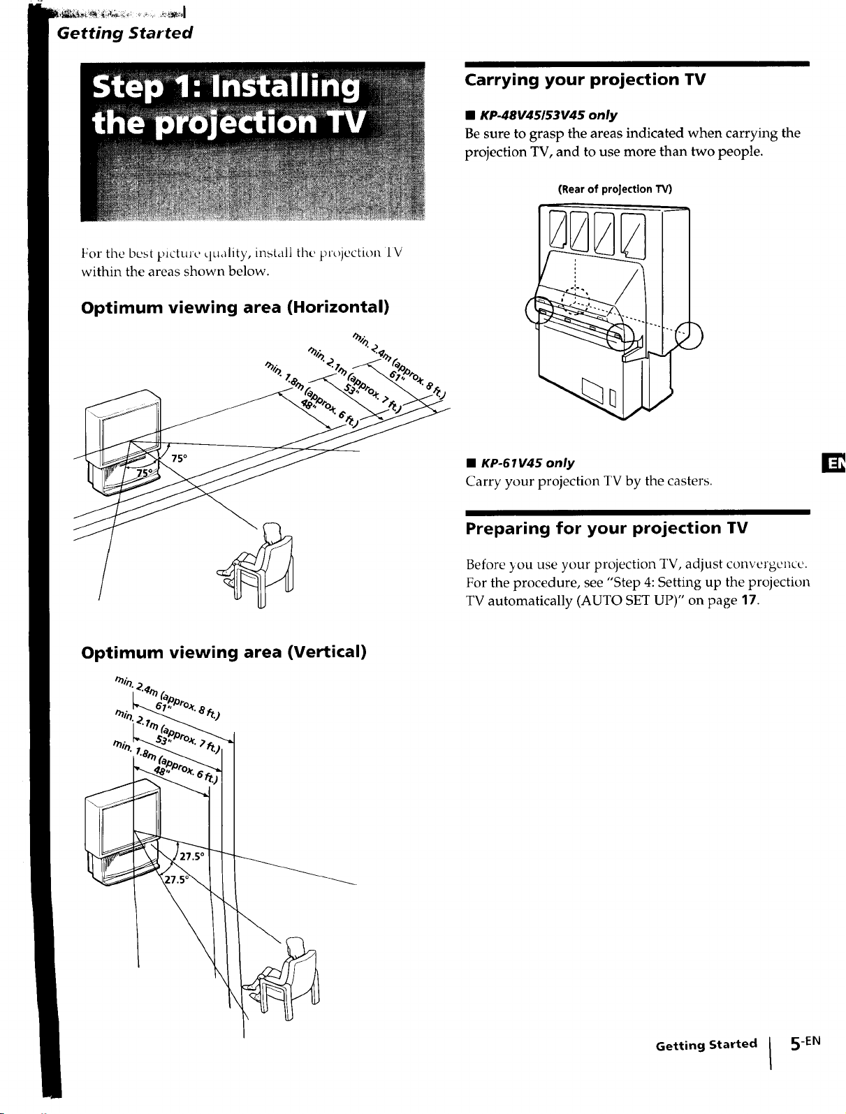
For the best p_cture quality, install the projection IV
within the areas shown below.
Carrying your projection TV
• KP-48V45153V45 only
Be sure to grasp the areas indicated when carrying the
projection TV, and to use more than two people.
(Rear of projection W)
Optimum viewing area (Horizontal)
Optimum viewing area (Vertical)
(
)
• KP-61V45 only
Carry your projection TV by the casters.
Preparing for your projection TV
Before _ou use your projection TV, adjust convergence.
For the procedure, see "Step 4: Setting up the projection
TV automatically (AUTO SET UP)" on page 17.
Getting Started I 5-EN
Although },ou _all use either an indoor or outdool _
antenna with your projection TV, we recommend that
you connect an outdoor antenna or a cable TV system
to get better picture quality.
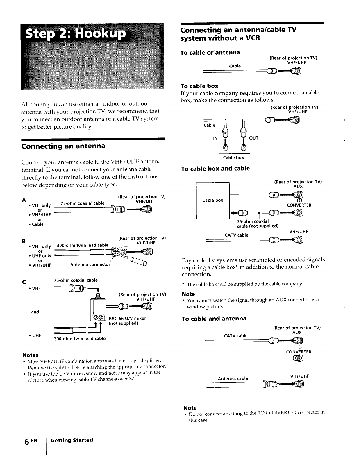
Connecting an antenna
Connecting an antenna/cable TV
system without a VCR
To cable or antenna
(Rear of projection TV)
Cable
VHF/UHF
To cable box
If your cable company requires you to connect a cable
box, make the connection as follows:
(Rear of projection TV)
VHF/UHF
-,,,,
Connect your antenna cable to the VHF/UHF antenna
terminal. If you cannot connect your antenna cable
directly to the terminal, follow one of the instructions
below depending on your cable type.
A
• VHF only
or
• VHF/UHF
or
• Cable
B
• VHF only
or
• UHF only
or
• VHF/UHF
C
• VHF
and __F
• UHF
75-ohm coaxial cable
300-ohm twin lead cable VHF/UHF
Antenna connector
75-ohm coaxial cable
--.---_ ===J_ (not supplied)
300-ohm twin lead cable
(Rear of projection TV)
VHF/UHF
(Rear of projection TV)
(Rear of projection TV)
EAC-66 UtV mixer
Cable box
To cable box and cable
(Rear of projection TV)
Cable box
75-ohm coaxial
cable (not supplied)
CATV cable
AUX
TO
CONVERTER
VHF/UHF
Pay cable TV systems use scrambled or encoded signals
requiring a cable box* in addition to the normal cable
connection.
* The cable box will be supplied by the cable company.
Note
• You cannot watch the signal through an AUX connector as a
window picture.
To cable and antenna
(Rear of projection TV)
CATV cable
AUX
Notes
• Most VHF/UHF combination antennas have a signal splitter.
Remove the splitter before attaching the appropriate connector.
• If you use the U/V mixer, snow and noise may appear in the
picture when viewing cable TV channels over 37.
6-EN I Getting Started
TO
CONVERTER
Antenna cable
Note
• Do not connect anything to the TO CONVERTER connector in
this case.
VHF/UHF
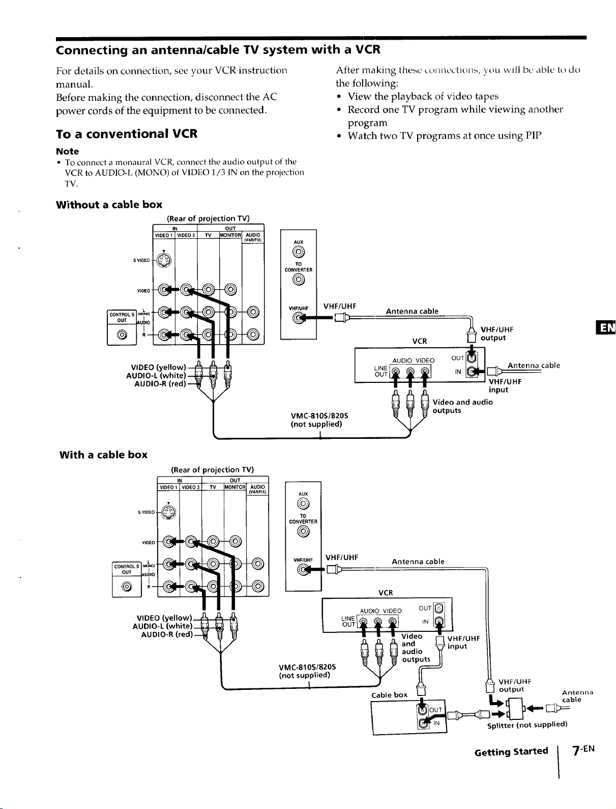
Connecting an antenna/cable TV system with a VCR
For details on connection, see your VCR instruction
manual.
Before making the connection, disconnect the AC
power cords of the equipment to be connected.
To a conventional VCR
Note
• To connect a monaural VCR, connect the audio output of the
VCR to AUDIO-L (MONO) of VIDEO 1/3 IN on the projection
TV.
Without a cable box
(Rear of projection TV)
IN
VIDEO 1 VIDE03
TV
@
VIDEO (yellow) _
AUDIO-L (white) _
AUDIO-R (red) --_
/
AUX I
©1
TO I
CONVERTER I
©1
VHF/UHF I VHF/UHF
VMC-810S/820S
(not supplied)
L
After making these ¢om_ections, you will be able to do
the following:
• View the playback of video tapes
• Record one TV program while viewing another
program
• Watch two TV programs at once using PIP
Antenna cable
VCR output
_ VHF/UHF
__0o,o v,o_oo0_--I
_'"__ [___t_A_tonnacab,e
iN _ VHF/UHF
outputs
_ ideo and audio
input
With a cable box
AUDIO-L (white)
(Rear of projection TV)
IN OUT
VIDEO 1 VIDEO 3 "rv MONITOF AUDIO
S VIDEO, _
V,DED_'_
VIDEO (yellow) i_ ,_
AUDIO-R (red) --_
_-@
(V_,R/FIX)
aux i
CONVERTER I
@1
VHF/UHF I VHF/UHF
VMC-810S/820S
(not supplied)
1
Antenna cable
VCR
LINE --
AUDIO VIDEO OUTI_ 1
• • • Video _'_ VHF/UHF
_ _ _ andaudio _input
r_ | _ rl_--_ cable
t VHF/UHF
output Antenna
,N I Splitter (not supplied)
Getting Started 7 -EN
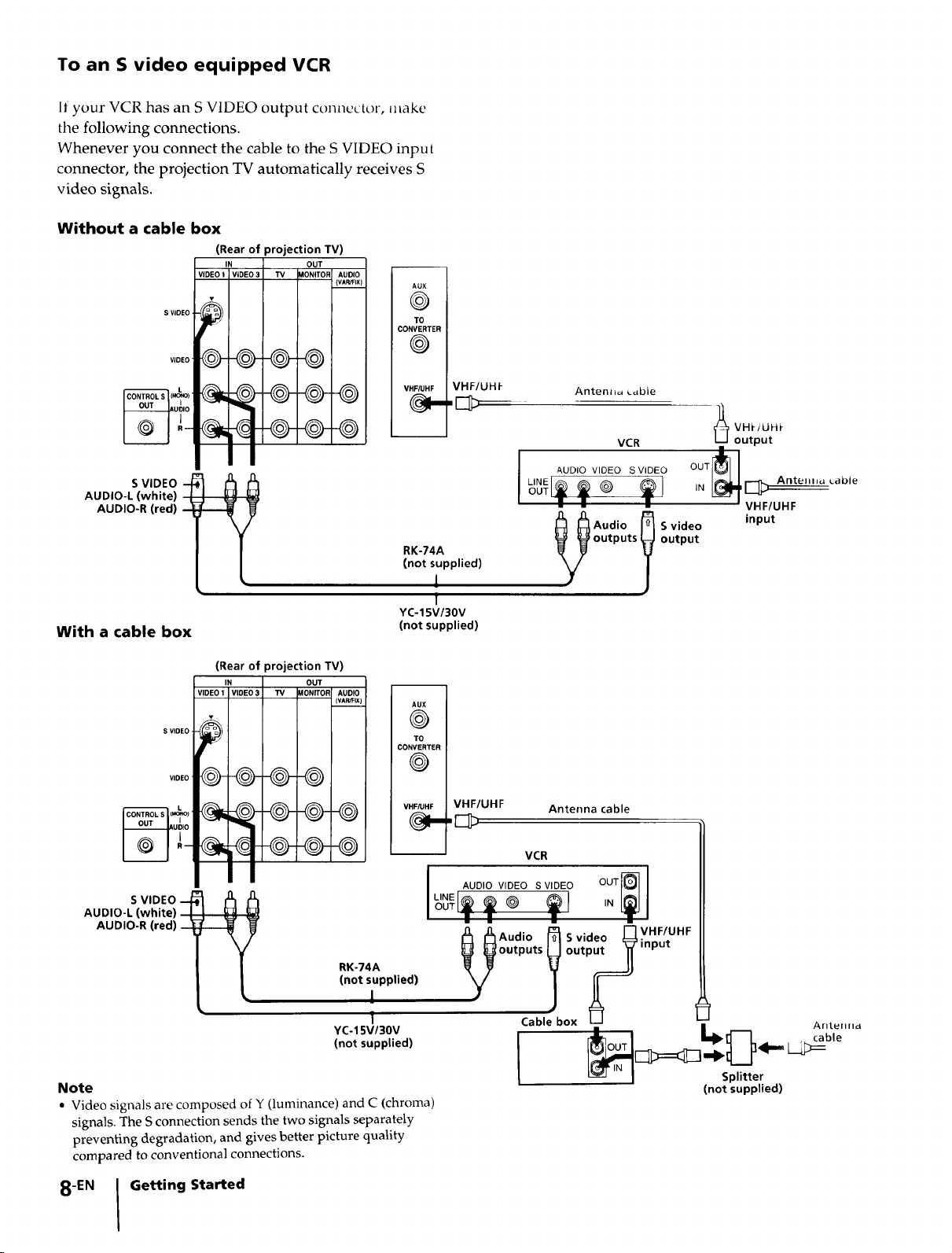
To an S video equipped VCR
If your VCR has an S VIDEO output connector, make
the following connections.
Whenever you connect the cable to the S VIDEO input
connector, the projection TV automatically receives S
video signals.
Without a cable box
(Rear of projection TV)
IN OUT
VIDEO t VIDEO 3 TV _IONITOF
AUDIO
(VAR/FIX)
AUX
©
CONVERTER
@
TO
S VIDEO -
AUDIO-L (white) i
AUDIO-R (red) -
With a cable box
S VIDEO
(Rear of projection TV)
IN OUT
VIDEO 1 VIDEO 3 "IV _ONITOI_ AUDIO
(VAWFIX)
VHF/UHF
RK-74A
(not supplied)
1
I
YC-15V/30V
(not supplied)
AUX
@
TO
CONVERTER
@
VHF/UHF
Antenn_ L_ble
VCR
I AUDIO VIDEO SVIDEO
OUT ))_
LINE
__]/_ udio S video
outputs output
Antenna cable
_ VHt/UHt
output
OUT _]4 E_ Ante a Lable
IN -- VHF/UHF
input
S VIDEO --
AUDIO-L (white) I
AUDIO-R (red)
RK-74A
(not supplied)
1
I
YC-15V/30V
(not supplied)
Note
• Video signals are composed of Y (luminance) and C (chroma)
signals. The S connection sends the two signals separately
preventing degradation, and gives better picture quality
compared to conventional connections.
8-EN I Getting Started
VCR
I _NE __AUDIO VIDEO S VIDEO OUT_-IIN[_
h h Audi° R Svideo _VHF/UHF
outputs output input
_[_:_ _ _][___=OUT LI_ _ _ CAa_lel ' ,,d
_-J ] Splitter
(not supplied)
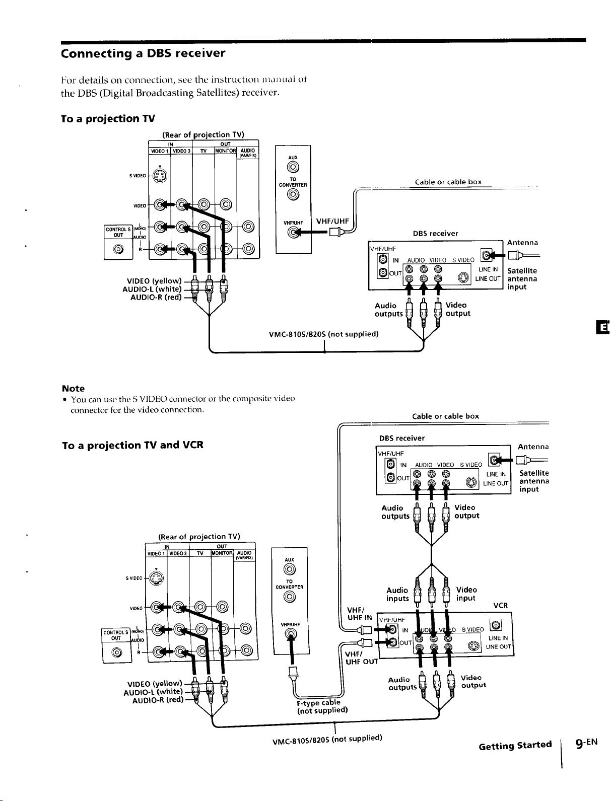
Connecting a DBS receiver
For details Ollconnection, see the inMruction n_,mual ot
the DBS (Digital Broadcasting Satellites) receiver.
To a projection TV
(Rear of projection TV)
IN OUT
VIDEO 1 I VIDEO 3 TV MONITOR AUDIO
(VAR/FIX)
S VIDEO @
V,DEO
@ ®
VIDEO (yellow) _
AUDIO-L (white)
AUDIO-R (red) --_
Note
• You can use the S VIDEO connector or the composite video
connector for the video connection.
To a projection TV and VCR
/
VMC-810S/820S (not supplied)
L
Cable or cable box
DBS receiver
II I1_11 IN AUDIO VIDEO SVIDEO
outputs output
Audio l I Video
DBS receiver
VHF/UHF [_L Antenna
)__ LINEIN I Satellite
Cable or cable box
OUT )) _ _ --I LINEINI Satellite
--_ IN IAUDIO VIDEO SVlDEO [_
'_ LINEOUTI inputantenna
I I
_4 Antenna
LINEOUT] iapuet na
(Rear of projection TV)
IN OUT
VIDEO 1 VIDEO3 TV _ONITOR AUDIO
S VIDEO @
V,OE0
AUDIO-L (white) --
AUDIO-R (red)-
VIDEO (yellow) ,_
(VAPJFIX)
AU
@1
T(
CONVERTER J
@1
VHF/UHF I
F-type cable
(not supplied)
VMC-810S/820S (not supplied)
outputs output
Audio l I Video
Audio
inputs
x_ Video
input
Video
output
;VIDEO LIN_EIN /
VCR
LINE OUT /
Getting Started
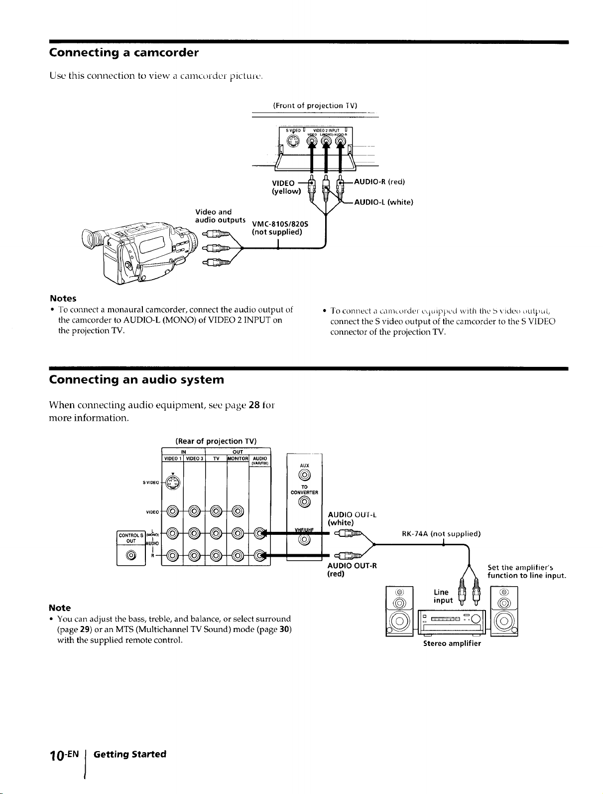
Connecting a camcorder
Use this connection to view a camcorder picture.
(Front of projection IV)
VIDEO
(yellow) _
Video and
ud,o outputs _/nMoC.s8ulOp_18(_ S
Notes
• To connect a monaural camcorder, connect the audio output of
the camcorder to AUDIO-L (MONa) of VIDEO 2 INPUT on
the projection TV.
Connecting an audio system
When connecting audio equipment, see page 28 for
more information.
(Rear of projection TV)
VIDEO 1 !IDEO 3 TV
S VIDEO
@- @5@-
IN
I
OUT
MONITOF AUDIO
{VAR/FIX)
-@
-@-@5@-
-0 @+@-
0©
AUX
®
TO
CONVERTER
©
VHF/BHF
AUDIO-R (red)
AUDIO-L (white)
• To connect a call/c_.)rdel cHuIppcd with the 5 video OLItJ_)LII.,
connect the S video output of the camcorder to the S VIDEO
connector of the projection TV.
AUDIO OUI-L
(white)
RK-74A (not supplied)
1
AUDIO OUT-R
(red)
iJX Set the amplifier's
d _ function to line input.
Note
• You can adjust the bass, treble, and balance, or select surround
(page 29) or an MTS (Multichannel TV Sound) mode (page 30)
with the supplied remote control.
O-EN Getting Started
inputVV J_J
o=o11 1
Line _ _ i__ _
Stereo amplifier
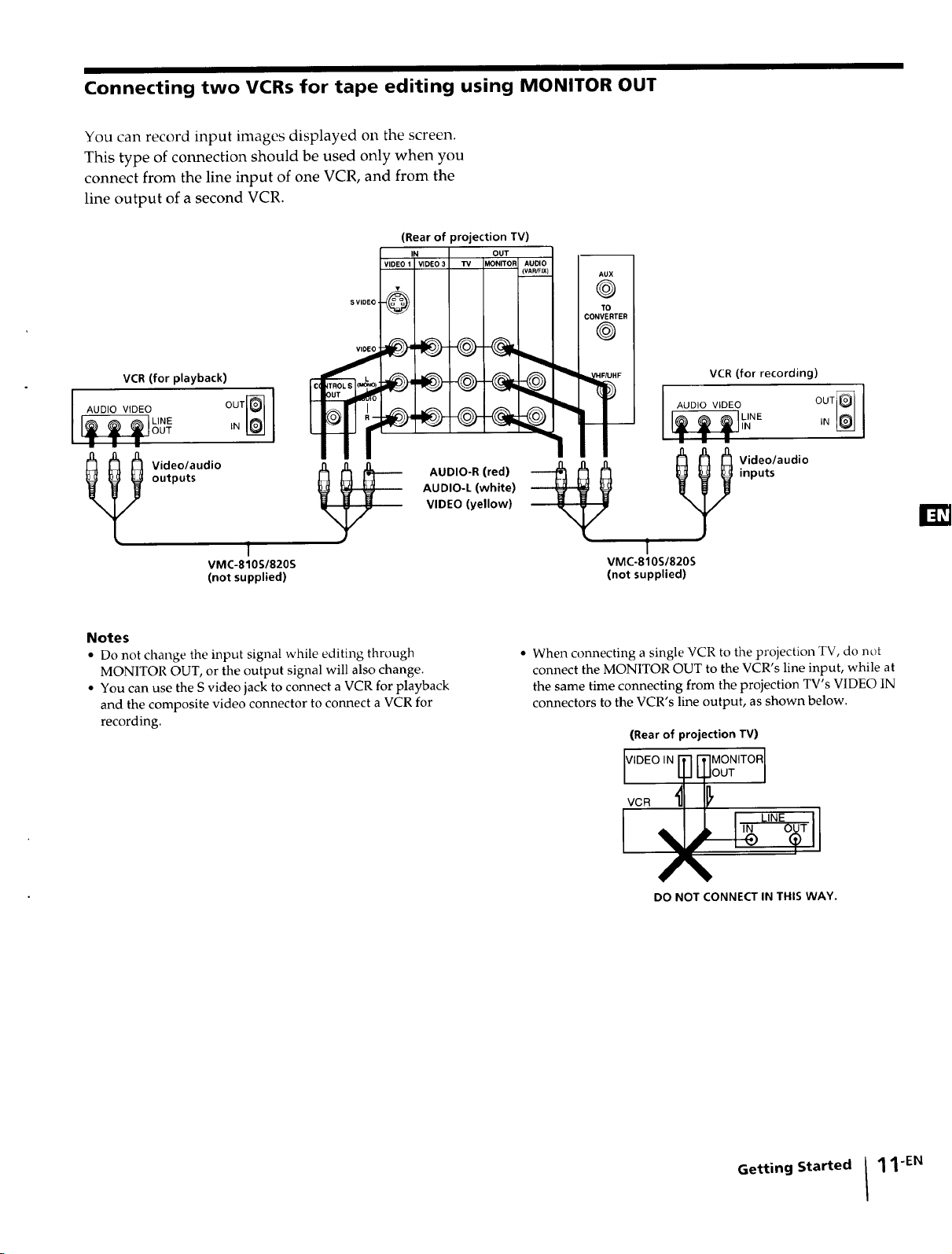
Connecting two VCRs for tape editing using MONITOR OUT
You can record input images displayed on the screen.
This type of connection should be used only when you
connect from the line input of one VCR, and from the
line output of a second VCR.
(Rear of projection TV)
v,o.o,'%.o._v o.%.,v.._o
S VIDEO
VCR(for playback)
I AUDIO VIDEO OUT_'_
outputs
_ ideo/audio
1
VMC-810S/820S
(not supplied)
Notes
• Do not change the input signal while editing through
MONITOR OUT, or the output signal will also change.
• You can use the S video jack to connect a VCR for playback
and the composite video connector to connect a VCR for
recording.
E
----- AUDIO-R (red)
AUDIO-L (white)
VIDEO (yellow)
/
K n
) I
_ON_
FITER
)1
AHFI VCR (for recording)
__)I [ Li__IL/NEAUDIOVIDEO
i w m
inputs
v
VMC-810S/820S
(not supplied)
• When connecting a single VCR to the projection TV, do not
connect the MONITOR OUT to the VCR's line input, while at
the same time connecting from the projection TV's VIDEO IN
connectors to the VCR's line output, as shown below.
_ ideo/audio
1
(Rear of projection TV)
DO NOT CONNECT IN THIS WAY.
Getting Started I 11"EN
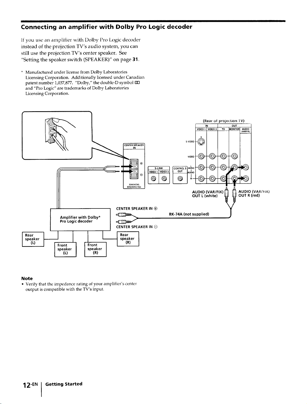
Connecting an amplifier with Dolby Pro Logic decoder
If you use an amplifier with Dolby Pro Logic decoder
instead of the projection TV's audio system, you can
still use the projection TV's center speaker. See
"Setting the speaker switch (SPEAKER)" on page 31.
* Manufactured under license from Dolby Laboratories
Licensing Corporation. Additionally licensed under Canadian
patent number 1,037,877. "Dolby," the double-D symbol [113
and "Pro Logic" are trademarks of Dolby Laboratories
Licensing Corporation.
(Rear of projection IV)
IN OUT
VIDEO 1 VIDEO 3 TV MONITOR AUDIO
(VAR/FIX)
CENTERI_PEAKER
G
30W(NOM}
60W(MAX) 16_
CENTERSPEAKERIN (_
Amplifier with Dolby*
Pro Logic decoder
CENTERSPEAKER IN @
,p er ,0eo,or
.ear, I r,t" ar
Note
• Verify that the impedance rating of your amplifier's center
output is compatible with the TV's input.
Front I (R)
speaker I
(L) I
$ VIDEO
U IO
AUDIO(VARmX)_
OUT L (white) _ y
RK-74A (not supplied) )
Y
AUDIO (VAN/I-I×)
OUT R (red)
12"EN Getting Started
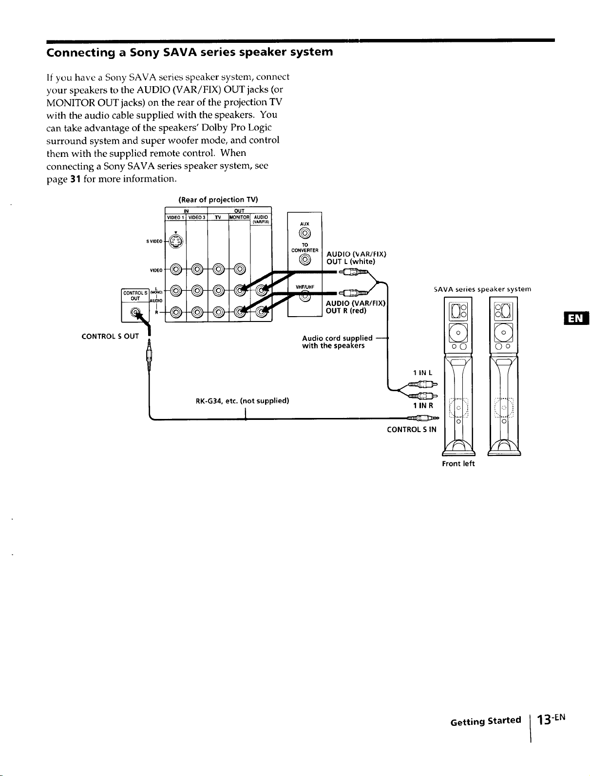
Connecting a Sony SAVA series speaker system
If you have a Sony SAVA series speaker system, connect
your speakers to the AUDIO (VAR/FIX) OUT jacks (or
MONITOR OUT jacks) on the rear of the projection TV
with the audio cable supplied with the speakers. You
can take advantage of the speakers' Dolby Pro Logic
surround system and super woofer mode, and control
them with the supplied remote control. When
connecting a Sony SAVA series speaker system, see
page 31 for more information.
(Rear of projection TV)
S VIDEO
IN
VIDEO 1 I VIDEO
@
OUT
TV _IONITOR AUDIO
(VAR/FtX)
AUX
©
TO
CONVERTER
®
VIDEO
-0@
J
r
ui,°
CONTROL S OUT "
Audio cord supplied m
with the speakers
AUDIO (_AR/FIX)
OUT L (white)
2>
AUDIO (VAR/FIX)
OUT R (red)
SAVA series speaker system
RK-G34, etc. (not supplied)
I
IlNL
IlNR
==:z_==
CONTROL S IN
Front left
Getting Started I 13-EN
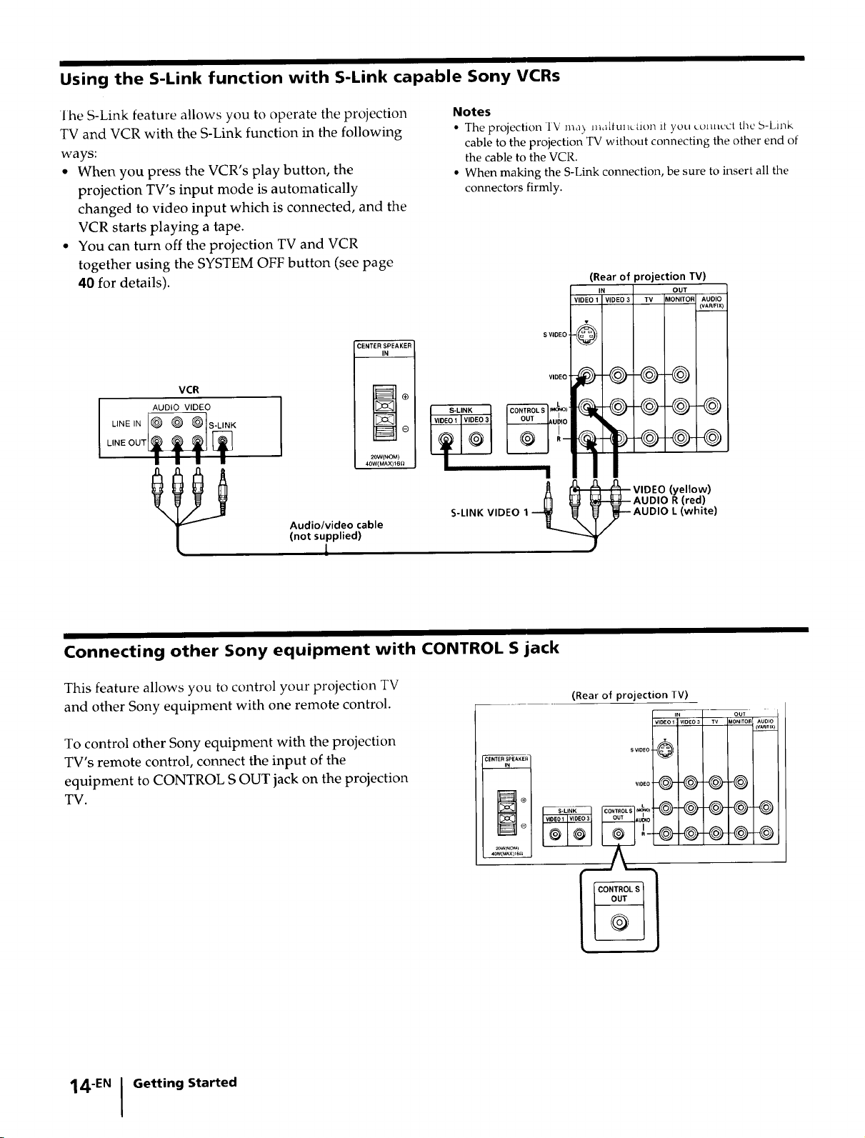
Using the S-Link function with S-Link capable Sony VCRs
lhe S-Link feature allows you to operate the projection
TV and VCR with the S-Link function in the following
ways:
* When you press the VCR's play button, the
projection TV's input mode is automatically
changed to video input which is connected, and the
VCR starts playing a tape.
• You can turn off the projection TV and VCR
together using the SYSTEM OFF button (see page
40 for details).
CENTER SPEAKEF
IN
VCR
AUDIO VIDEO
U.E,. @ @ @ S-.,NK
LiNE OUT_ )_ [_
I I I
Audio/video cable
(not supplied)
20W(NOM)
40W(MAX)16(]
L
Notes
• The projection IV ma_ maltu]_ction it you L_)tULcctthe S-Link
cable to the projection TV without connecting the other end of
the cable to the VCR,
• When making the S-Link connection, be sure to insert all the
connectors firmly.
(Rear of projection TV)
IN OUT
S VIDEO
I
S-LINK VIDEO 1 ---_ _ _
I
IDEO VII 0 3 I TV IMONITORI AUDIO
VIDEO (yellow)
--AUDIO R (red)
-AUDIO L (white)
I (VAPJFIX)
Connecting other Sony equipment with CONTROL S jack
This feature allows you to control your projection TV
and other Sony equipment with one remote control.
To control other Sony equipment with the projection
TV's remote control, connect the input of the
equipment to CONTROL S OUT jack on the projection
TV.
(Rear of projection TV)
VIDEO1 VIDEO3 TV AONITORAUDIO
SVIOEO
VIDEO @ @-@-©
IN out
(VAR_IX)
@-@-@--@
@-@-@-®
14EN I Getting Started
 Loading...