

Sony KP-61HS30, KP-61HS20, KP-53HS30, KP-53HS20, KP-43HT20 Owner’s Manual

SONY. 4.o81.14_.,,.
KP-43HT20
KP-53HS20
KP-53HS30
KP-61HS20
KP-61HS30
Hi.Scan
WARNING
To prevent fire or shock hazard, do not
expose the projection TV to rain or
moisture.
PRECAUCION
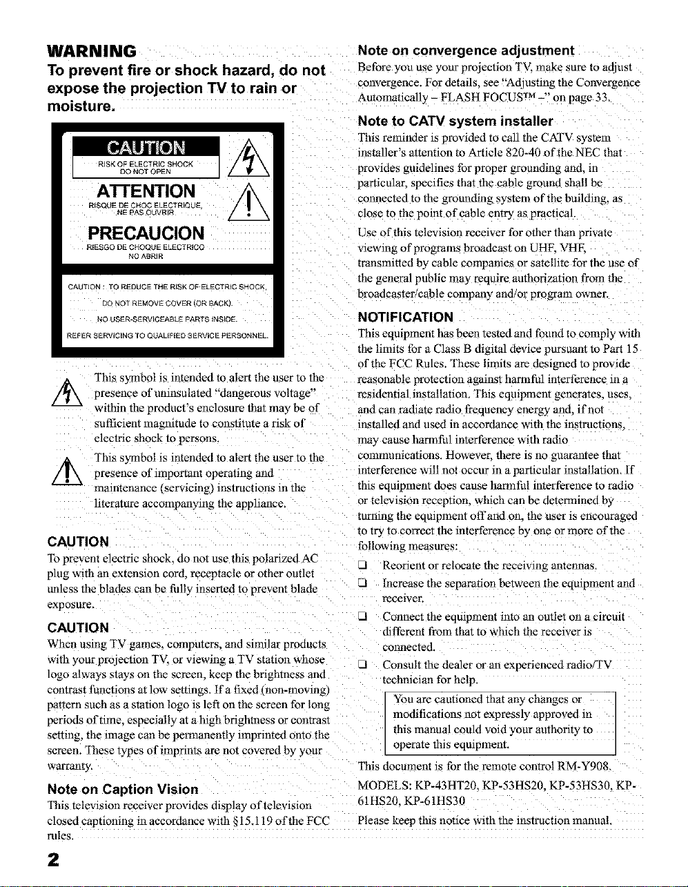
l'his symbol is intended to alert the user to the
Ax
¢/_k This symbol is intended to alert the user to the
CAUTION
qb prevent electric shock, do not use this polarized AC
plug with an extension cord. receptacle or other outlet
unless the blades can be fully inserted to prevent blade
exposure_
CAUTION
When using TV games, computers, and similar products
with your protection TV. or viewing a TV station whose
logo always stays on the screen, keep the brightness and technician for help,
contrast functions at low settings, Ifa fixed non-moving)
pattern such as a station logo is left on the screen for long
periods of time. especially at a high brightness or contrast
setting, the _mage can be permanently _mprinted onto the
screen. These types of imprints are not covered by your
warrallry
Note on Caption Vision
Thls televismn recelver provides display of television
closed capnomng in accordance with _15.119 of the FCC
presence of uninsulated "dangerous voltage"
within the product's enclosure that may be of
sufficient magnitude to constitute a risk of
electric shock to persons.
presence of important operating and
maintenance ¢servmmg) mstrucuons in the
[iterature accompanying the apphance_
Note on convergence adjustment
Before you use your pro3ectmn TV. make sure to adJUSt
convergence. For details, see"Adlustmg the Convergence
Automatically - FLASH FOCUS TM -" on page 33,
Note to CATV system installer
This reminder is provided to call the CKFV system
installer's attention to Article 820-40 of the NEC that
provides guidelines for proper grounding and. m
particular, specifies that the cable ground shall be
connected to the grounding system of the building, as
close to the point of cable entry as practical.
Use of this television receiver for other than private
viewing of programs broadcast on UHK VHE
transmitted by cable compahies or satellite for the use of
the general public may require authorization from the
broadcaster/cable company and/or progxam owner.
NOTIFICATION
This equipment has been tested and found to comply with
the limits for a Class B digital device pursuant to Part 15
of the FCC Rules. These limits are designed to provide
reasonable protecuon against harmful interference in a
residential installation, This equipment generates, uses.
and can radiate radio frequency energy and. if not
installed and used in accordance with the instractiorLs.
may cause harmful interference with radio
commumcatmns. However. there is no guarantee that
interference will not occur in a particular installation, if
this eqmpment does cause harmful interference to radio
or television recephon, which can be determined by
turning the eqmpment offand on. the user is encouraged
to try to correct the interference by one or more of the
following measures:
El Reorient or relocate the receiving antennas,
Increase the separation between the equipment and
receiver.
Connect the equipment into an outlet on a circuit
different from that to which the receiver is
connected.
El Consult the dealer or an experienced radio/T'_
You are cautioned that any changes or
modifications not expressly approved m
this manual could void your authority to
operate this eqmpmem,
This document is for the remote control RM-Y908,
MODELS: KP-43HT20. KP-53HS20. KP-53HS36. KP-
61HS20. KP-61HS30
Please keep this notice with the instruction manual.
rules.
2
Safety
d Operate the projection TV only on 120 V AC.
-3 The plug is designed, for safety purposes, to fit into
the wall outlet only one way. If you are unable to
insert the plug full 3 into the outlet, contacl your
dealer.
-I If any hquid or solid object should fall inside the
cabinet, unplug the projection TV immediate1) and
have it checked by qualified service pm_onnel
before operating it further.
_3 If you will not be using the projection TV for several
days. disconnect the power by pulling the plug itself.
Never pull on the cord.
For details concerning safety precauuons, see
"Important Safeguards" on page 4
Installing
_3 lb prevent internal heat buildup, do not block the
ventilation openmgs_
Do not install the projection TV in a hot or humid
place, or m a place subJect to excesswe dust ol
mechanical vibration.
_3 Avoid operating the projection TV at temperature
below 5°C ¢41_F .
d If the projection TV _s transported directly from a
cold to a warm location, or if the room temperature
changes suddenly, the picture may be blurred or
show poor color. In this case, please wait a few hours
to let the moisture evaporate before turning on the
projection TV.
To obtain the besl picture, do not expose the screen
to direct illumination or direct sunhght, it is
recommended to use spot lighting directed down
from the ceiling or to cover the windows that face
the screen with opaque drapery, it is desirable to
install the projection TV in a room where the floo_
and walls are not of a reflective material.
]/ll-qllnund" TruSurround is a trademark of
H==v'_t-=_,.= _. SRS Labs. inc. SRS and the SRS
wUlIonlD _.WJ
of SRS Labs. inc. in the United States and salecte(
foreign countries. SRS and TruSurround are incorporated
under license from SRS Labs. thc. and is protected under
United States Patent Nos. 4.748.669 and 4. 841 572 with
numerous additional issued and pending foreign patents.
Pro'chase of this product does not convey the right to sell
recordings made with the TruSurrouod technology=
BBE and BBE Symbol are trademarks of BBE Sound.
Inc. and are licensed b_*BBE Sound. Inc. under U.S.
Patent No. 4.638.258 and 4.482.866.
symbol are registered trademarks
ATTENTION
Pour pr4venir les chocs 41ectriques, ne pas utiliser cette
fiche polaris& avec un prolongatem; une prise de courant
ou une autre sortie de courant, sauf si les lames peuvenr
tre inser4es/_ fond sans en laisser aucune partie
deco_o vert.
Owner's Record
The model and serial numbers are located at the rear of
the proJection TV below the Sony logo. on the sticker.
and also on the TV box, white label]. Record these
numbe_ m the spaces provided below. Refer to them
whenever you call upon your Sony dealer regarding this
product.
Model No
Serial No.
As an ENERGY STAR ®
/D_=_, '-,_ determined that this product
*'_'1._4 meets the ENERGY STAR ®
ENERGY STAR is a U.S. registered mark.
Partner, Sony Corporation has
guidelines for energy efficiency,
r
3
Important Safeguards
For your protection, please read these instructions
completely, and keep this manual for future reference.
Carefully observe and comply with all warnings, caunons
and instructions placed on the set or described in the
operaung lnstraclAons or servme manual.
WARNING
To guard against injury, the following basic safety
precauuons should be observed in the installation, use
and servicing of the set,
Use
Power Sources
This set should be operated only from
the type of power source indicated on (?_
the serial/model plate_ if you are nol sure _ _'_ _-_-
of the type of electrical power supplied .J
to your home. consult your dealer or
local power company. For those sets designed to operate
from battery power refer to tile operating mstructmns.
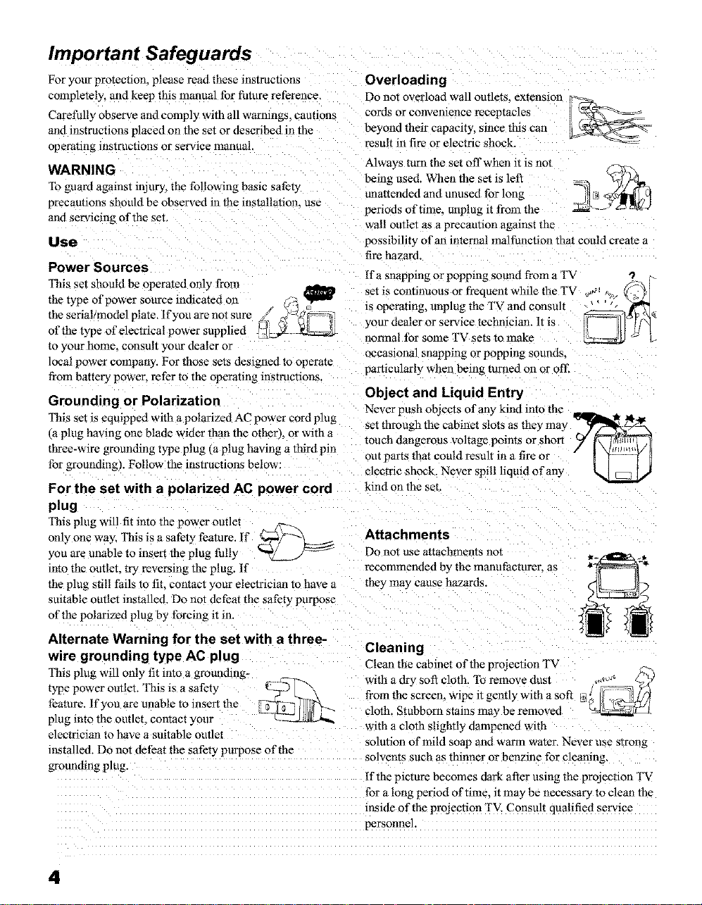
Grounding or Polarization
This set is eq0ipped with a polarized AC power cord plug
(a plug having one blade wider than the other_, or with a
three-wire grounding type plug (a plug having a third pin
for grounffmg). Follow the instructions below:
For the set with a polarized AC power cord
plug
This plug will fit into the power outlet
only one way, This is a safer? feature, if _F_-2
you are unable to insert the plug fully _
into the outlet, try reversing the plug. If
the plug still fails to fit. contact your electrician to have a
suitable outlet installed. Do not defeat the safet': purpose
of the polarized plug by forcing _tm.
Overloading
Do not overload wall outlets, exrensmn
cords or convenience receptacles
beyond their capacity, since this can
result in fire or electric shock.
Always turn the set offwben it is not
being used. When the set is left
unattended and unused for long
periods of time. unplug it from the
wall outlet as a precautmn against the
possibility of an internal malfunction that could create a
fire hazard.
Ifa snapping or poppmg sound from _ TV _._._(.
set is continuous or frequent while the TV _,_ _o_ _.:
_s operating, unplug the TV and consult ' ' -
your dealer or service technician. It is
normal for some TV sets to make
occasmnal snapping or popping sounds.
particularly when being turned on or ot'l_
Object and Liquid Entry
Never push objects of any kind into the
set through the cabinet slots as they may _ll_z_ N
touch dangerous voltage points or short )f r\ ]:_]
out
electric shock. Never spill liquid of any k_l _ ljJ
kind on the set.
Attachments
Do not use attachments not
recommended b3 the mamtfacturer, as
they may cause hazards.
that could result in a fire or " I _-:--_ ;]
parts
i B
Alternate Warning for the set with a three-
wwe grounding type AC plug
This plug will only fit into a grounding-
type power outlet. Tffts is a safety
_-_(q--.. with a dr5 sofi cloth, ]b remove dust
feature, if you are unable to insert the
plug into the outlet, contact your
electrician to have a suitable outlet
installed. Do not defeat the safety purpose of the solvents such as thinner or benzine for cleanin_
grounding plug.
Cleaning
Clean the cabinet of the proJection T\
from the screen, wipe it gently with a soft
cloth. Stubborn stains may be removed
with a cloth slightly dampened with
solution of mild soap and warm water, Never use strong
If the picture becomes dark after using the proJection TV
for a long period of time. it may be necessary to clean the
inside of the proJection TV. Consult qualified service
personnel.
4
Installation
Water and Moisture
Do not use power-line operated sets
near water -- for example, near a
bathtub, washbowl, kitchen sink. or
laundry tub. in a wet basement, or
r
_2_j
near a swimming pool. etc.
Accessories
Do no1 place the set on an unstable ,..],,_-)_
cart, stand, table or shelf. The set '_t \L,/I,/-)_"
may fall, causing serious injury to a \ _'_
child or an adult and serious damage _'_R _
to the set. Use only a cart or stand
recommended by the mam/facturer
for the specific model ofprojecuon
TV. An appliance and cart
combination should be moved with
care. Quick stops, excessive force.
and uneven surfaces may cause the appliance and cart
combination to overturn.
Ventilation
The slots and opemngs in the cabinet and in the back or
bottom are provided for necessary venhlahon, rib ensure
reliable operation of the set. and to protect it from
overheating, these slots and opemngs must never be
blocked or covered.
d Never cover the slots and opemngs
with a cloth or other materials.
Power-Cord Protection
Do not allow anything to rest on or roll
over the power cord. and do not place the
set where the power cord is subject ro
wear or abuse.
Antennas
Outdoor Antenna Grounding
If an outdoor anterma is installed, follow the precautions
below. An outdoor antenna system should not be locatec
m the vicinity of overhead power lines or other electric
light or power circmts, or where it can come m contact
with such power lines or circmts.
WHEN INSTALLING AN OUTDOOR ANTENNA
SYSTEM. EXTREME CARE SHOULD BE TAKEN TO
KEEP FROM CONTACTING SUCH POWER LINES
OR CIRCUITS AS CONTACT WITH THEM IS
ALMOST INVARIABLY FATAL.
Be sure the antenna system _sgrounded so as to prowde
some promctmn against voltage surges and built-up stauc
charges,
Section 810 of the National Electt-ical Code (NEC} in
USA and Section 54 of the Canadian Electrical Code in
Canada pro_i_desinformation with respect to proper
grounding of the mast and supporting structure.
grounding of the lead-in wire to an antenna discharge
tram size of grounding conductors, location of antenna
discharge umt, connecnon to gnsundmg electrodes, and
requirements for the grounding electrode.
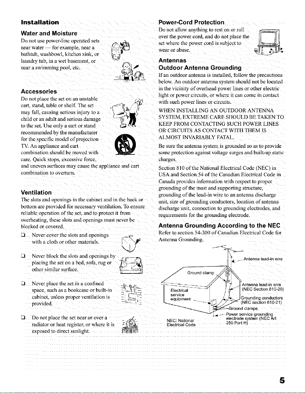
Antenna Grounding According to the NEC
Refer to section 54-300 of Canadian Electrical Code for
Antenna Grounding.
Never block the slots and openings by
placing the set on a bed. sofa. rug o_ __---_
other similar surface
Never place the set in a confined
space, such as a bookcase or built-in z_..... _-r--
cabinet, unless proper ventilation is _IE
provided. _ "-" [
d Do noI place the set near or over a "ag_._,[g-
radmtor or heat reglsmr, or where it is _)_1_
exposed to direct sunlight.
J Ground cla
mp_ _._4._ Antenna lead-inwire
/-
_- _ -- .... z_ ._Anennalead-inwire
serVlCmeent _ Grounding conductors
_:/ IElectri_fl -- _ _I(NEC Sect °n 810-201,
_IEC:National
---ectrical Code 250 Part H
.... NECsection 810-21_
_Power service grounding
Groundclamps
eIectrodesystem tNECArt
5
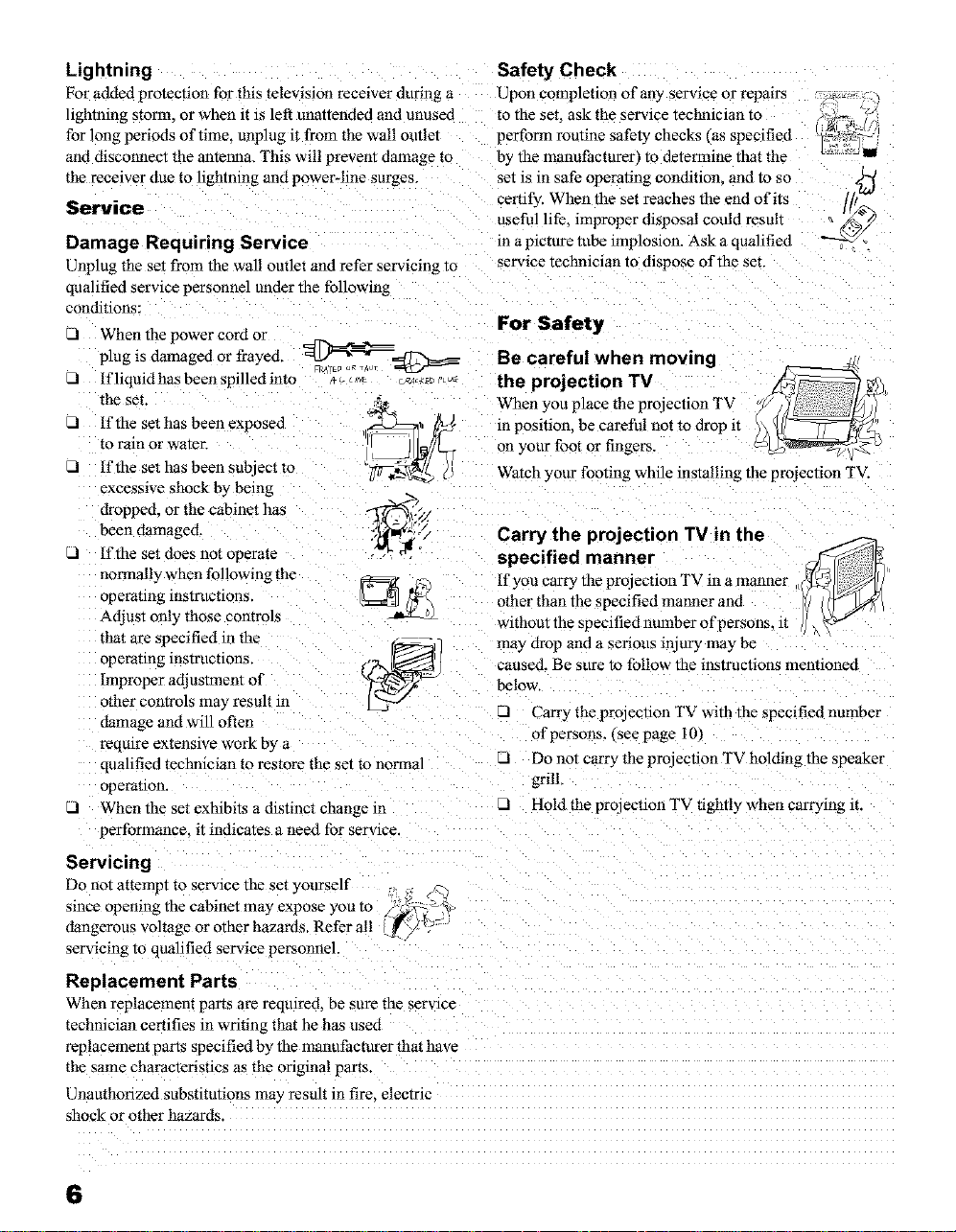
Lightning
For added protection for this television receiver during a
lightning storm, or when it is left unattended and unused
for long periods of time. unplug it from the wall outlet
and disconnect the antenna. This will prevent damage to
the receiver due to hghtning and power-line surges.
Service
Damage Requiring Service
Unplug the set from the wall outlet and refer servicing to
qualified service personnel under the following
conditions:
-I When the power cord or _alel_y
plug is damaged or frayed _@ Be careful when moving
.A
If liquid has been spilled into
the set. _,_ When you place the projection TV
_1 If the set has been exposed ,,=_2=_, ff-_),) in position, be careful not to drop it
to ram or water. U_ 1_,_'_ on your foot or fingers, c__
d If the set has been subject ro
excessive shock by bemg
dropped, or the cabinet has 'Sg
been damaged. _:/.
...I If the set does not operate
normally when following the
operating mstrucnons.
Adjust only those controls
that are specified in the --(o-,.-_ I
operating instructions.
Improper adjustment of
other controls ma_ result m
damage and will often
require extensive work by a
qualified techrdcian to restore the set to normal
operation.
d When the set exffthits a distinct change m
performance, it indicates a need for service.
¢ _ Ut?L
,_A,_ the projection TV
_ ,_*-_ (/ Watch your footmg whale lnsta mg the proJection TV.
Safety Check
Upon completion of any service or rep;J n-s
to the set. ask the service technician to
perform routine safety checks (as specified
by the manufacturer, to determine that the
set is in safe operating condmon, and to so 5_
certify. When the set reaches the end of its ,_.1[/_
useful life, improper disposal could result _ _'_
in a picture tube implosion. Ask a qualified _"'//
service technician to dispose of the set.
For
Carry the projection TV in the
specified manner
If you carry the projectmn TV m a manner
other than the specified manner and
without the specified number of persons, it
may drop and a serious injury may be
caused. Be sure to follow the instructions mentioned
below.
Carry the projection TV with the specified number
of persons, tsee page i 0/
LI Do not carry the projectmn TV holding the speaker
grilk
VA Hold the projectmn TV tightly when carrying it.
Servicing
Do not attempt to service the set yourself
since opemng the cabinet may expose you to
dangerous voltage or other hazards. Refer all
servmmg to qualified service personnel.
Replacement Parts
When replacement parts are required, be sure the service
technician certifies in writing that he has used
replacement parts specified by the manufacturer that have
the same characteristics as the original parrs
Unauthorized substitutions may result in fire. electric
shock or other hazards.
6
Contents
Important Safeguards ............................................... 4
Introducing the Sony Projection TV
Presemmg the Sony Projection TV .......................... 8
Using tl_ts manual .................................................... o
Installing and Connecting the
Projection TV
Contents ................................................................. 10
Inserting Batteries to the Remote Control ............. 10
Carrying Your ProJection TV ................................ 10
Installing the Projection TV ................................... 11
Connector Types .................................................... 12
ProJection TV Controls and Connectors ................ l3
Basic Connections (Connecting Cable TV or
Antenna _......................................................... 16
Connecting a VCR and Cable ................................ 19
Connecting a VCR and Cable Box ........................ 20
Connecung Two VCRs for Tape Editing .............. 22
Connecting a Satellite Receiver ............................. 23
Connecting a Satellite Receiver with a VCR ......... 24
Connecting an Audio Receiver .............................. 25
Connecting a DVD Player with Component
Video Connecto_ .......................................... 26
Connecting a DVD Player with
A/V Connectors ............................................. 27
Connecting a Digital TV Receiver ......................... 28
Connecting a Camcorder ....................................... 29
Connecting an AV Receiver .................................. 30
Using the CONTROL S Feature ............................ 31
Setting Up the Proiection TV Automaticall'y ......... 32
Adjushng the Convergence Automatically
- FLASH FOCUS TM -, .................................. 33
Using the Features
Using the Remote Control ..................................... 34
Watching the TV .................................................... 37
Watching the Digital TV ....................................... 39
Using Favorite Channels ........................................ 40
Usmg Twin View TM ............................................... 41
Using the Freeze Function ..................................... 44
Using Channel Index ............................................. 45
Using the Menus
Ovelwlew ................................................................ 47
Using the Video Menu .......................................... 48
Usm_ the Audio Metal .......................................... 50
Using the Channel Menu ...................................... 52
Using the Parent Menu ......................................... 54
Using the Timer Menu .......................................... 62
Using the Setup Menu .......................................... 63
Other Information
Programming the Remote Control ......................... 65
Operating Other Components with Your
ProJection TV Remote Control ...................... 68
Troubleshoonng ..................................................... 70
Specifications ......................................................... 73
7
Presenting the Sony Projection TV
Thank you for purchasing the Sony Projection TV.
This manual is for models KP-43HT20, KP-53HS20, KP-53HS30
61HS20 and KP-61HS30.
Model KP-53HS30 is used for illustration purposes.
KP-
Features
Some of the features that you will enjoy with your new projection TV
include:
O Hi Scan 1080 : Enables you to receive the 1080i, 720p, 480p and 480i
TM
digital TV formats. By using the VIDEO 5/6 IN jacks, you can connect
a DTV (digital television) receiver to view DTV programs.
O DRC TM Multi-Function: Unlike conventional line doublers, the DRC
feature doubles vertical and horizontal lines, resulting in four times the
density for quality sources such as DVD, Satellite and Digital
camcorder.
CineMotion : Using the 2-3 Pull-Down technology, the CineMotion
TM
feature allows you to obtain a smooth picture movement when playing
back movies or other video sources on film.
• * _M , ,
Twin View : Using MultMmage Driver (MID-X), Twin View allows
you to watch two programs side by side with the ability to zoom in one
picture and listen to selected window. You can watch pictures from two
different sources (1080i, 720p, 480p or 480i) simultaneously.
16:9 Enhancement: Vertical Compression technology that maximizes
ricture resolution on anamorphic' or enhanced for wide screen
sources, including selected DVDs.
Steady Sound_M: Equalizes volume levels so there is consistent output
between progranas and commercials.
Parental Control: V-Chip technology allows parents to block
unsuitable programming for younger viewers.
Component Video Inputs: Offers the best video quality for DVD
(480p, 480i) and Digital Set-top box (1080i, 720p, 480p, 480i)
connections.
O S-VIDEO Inputs: Provides a high-quality image for connected
equipment.
O Favorite Channel Preview: Preview up to eight favorite channels
without leaving the current channel.
8
Introducing the Sony Projection TV
Using this manual
V_l Channel Index: Allows you to view and choose from twelve programs.
T_
LI Flash Focus : Allows you to adjust convergence automatically.
We recommund that you carefully review the contents of the following four r0
sections in the order provided to ensure that you fully understand the o
operation of your new projection TV. ._
1 installing and Connecting the Projection TV _'r0
This section guides you through your initial setup. It shows you how tc
install your projection TV. to connect your new components and to connect
the antenna and cable.
2 Using the Features
This section shows you how to begin using your new projection TV. It
shows you how to use your remote control functions.
3 Using the menus
This section teaches you how to access on-screen menus and adjust your
projection TV settings.
5"
¢1
€3
o
Instructions in this manual are written for the remote control. Similar
controls may be found on the projecuon TV console.
9
Contents
Your box contains your new projection TV, a remote control and two AA
batteries. No peripheral cables are included. If you intend to add additional
equipment to your projection TV, please check the hookup instructions for
your desired setup before you begin. You may need to purchase cables and/
or splitters to complete the hookup properly.
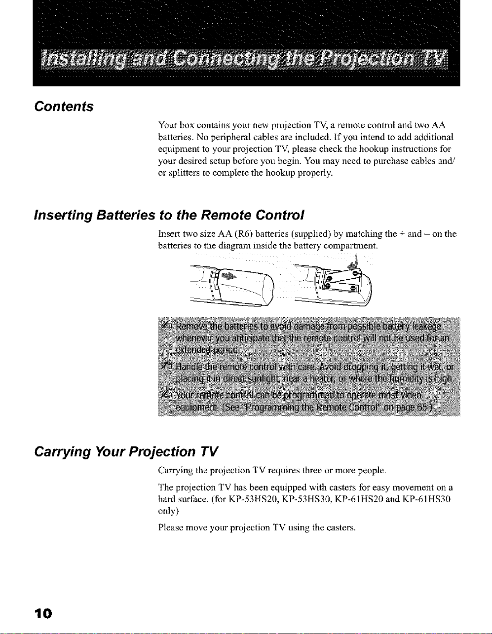
Inserting Batteries to the Remote Control
Insert two size AA (R6) batteries (supplied) by matching the + and - on the
batteries to the diagram inside the battery compartment.
Carrying Your Projection TV
Carrying the projection TV requires three or more people.
The projection TV has been equipped with casters for easy movement on a
hard surface. (for KP-53HS20, KP-53HS30, KP-61HS20 and KP-61HS30
only)
Please move your projection TV using the casters.
10
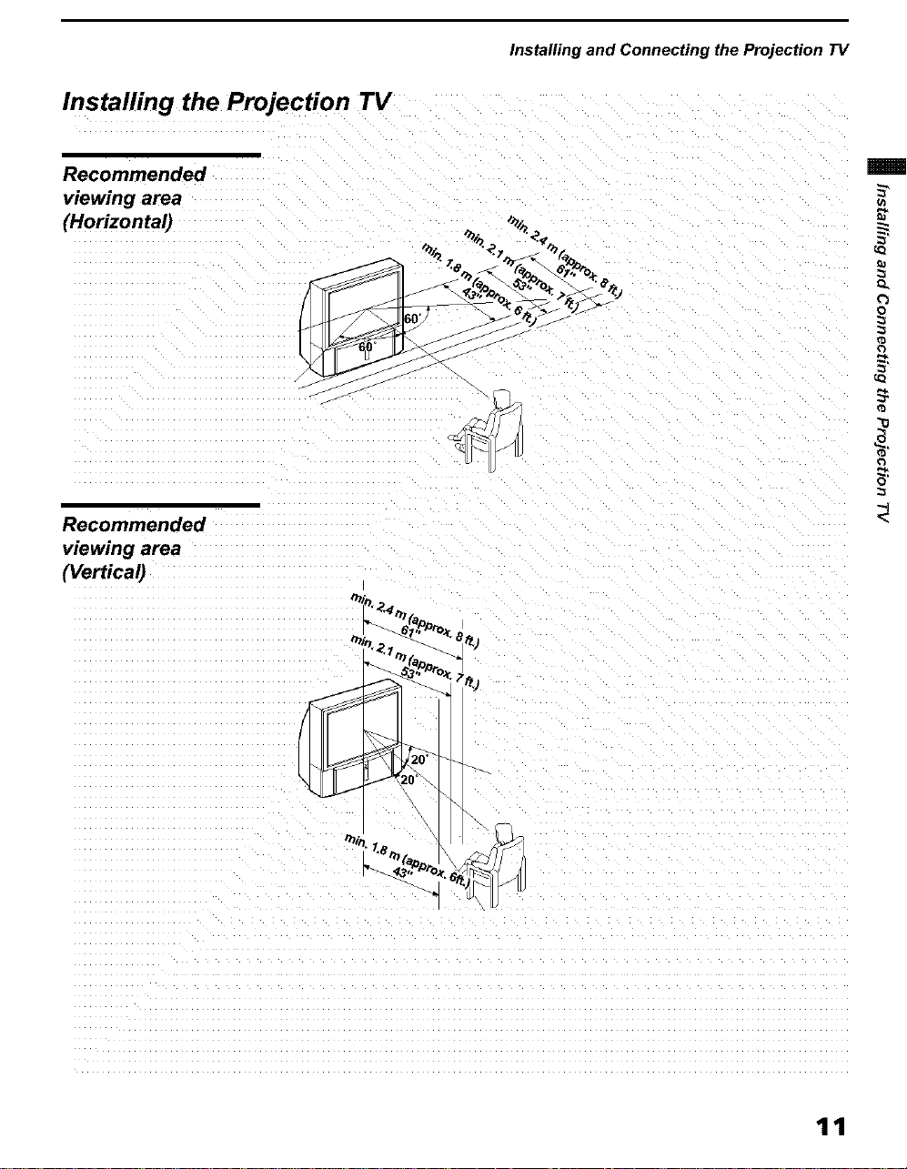
Installing the Projection TV
Recommended
viewing area
(Horizontal)
Installing and Connecting the Projection TV
_n
Q.
o
Recommended
viewing area
(Vertical)
[
0
11
Installing and Connecting the Projection TV
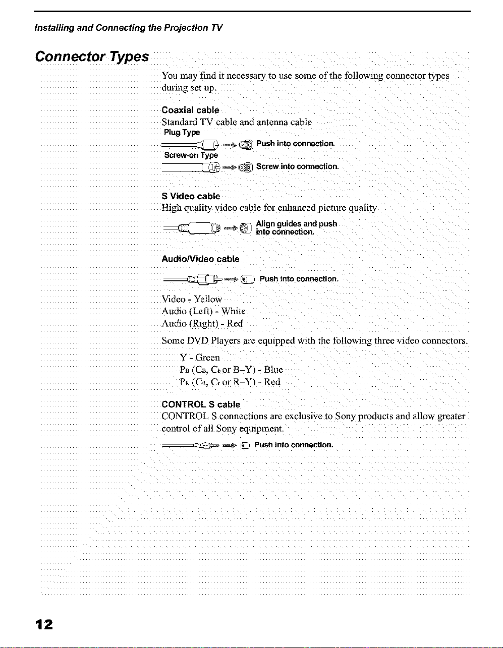
Connector Types
You may find it necessary to use some of the following connector types
during set up.
Coaxial cable
Standard TV cable and antenna cable
Plug Type
Screw-on Type
S Video cable
High quality video cable for enhanced picture qualit3
__ Alignguidesand push
Audio/Video cable
Video - Yellow
_udio (Left_ - White
Audio (Right) - Red
Some DVD Players arc eqmppcd with the following three video connectors.
Y - Green
PB, CB. Cbor BY_ - Blue
PR tCR. Cr or RY _- Red
_(_ Push into connection.
_ _ Screw into connection.
intoconnection.
_ _ Pushinto connection.
12
CONTROL S cable
CONTROL S connections are exclusive to Sony products and allow greater
control of all Sony eqmpmenr.
__zz_ _ _ Pushinto connection.
Installing and Connecting the Projection TV
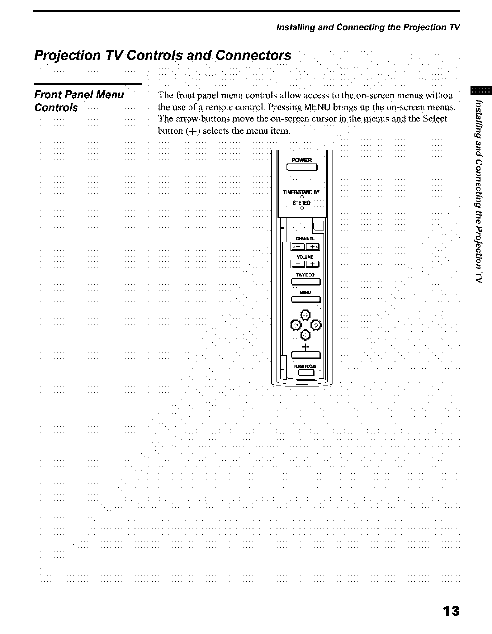
Projection TV Controls and Connectors
Front Panel Menu The front panel menu controls allow access to the on-screen menus without
Controls the use of a remote control. Pressing MENU brings up the on-screen menus.
The arrow buttons move the on-screen cursor in the menus and the Select
button (-t-) selects the menu item.
POWER
TIMBA/ST_D BY
_EF_O
VOLUME
T_AqDEO
N_J
oZo
+
I
I i,,_1_FOC,m
o
13
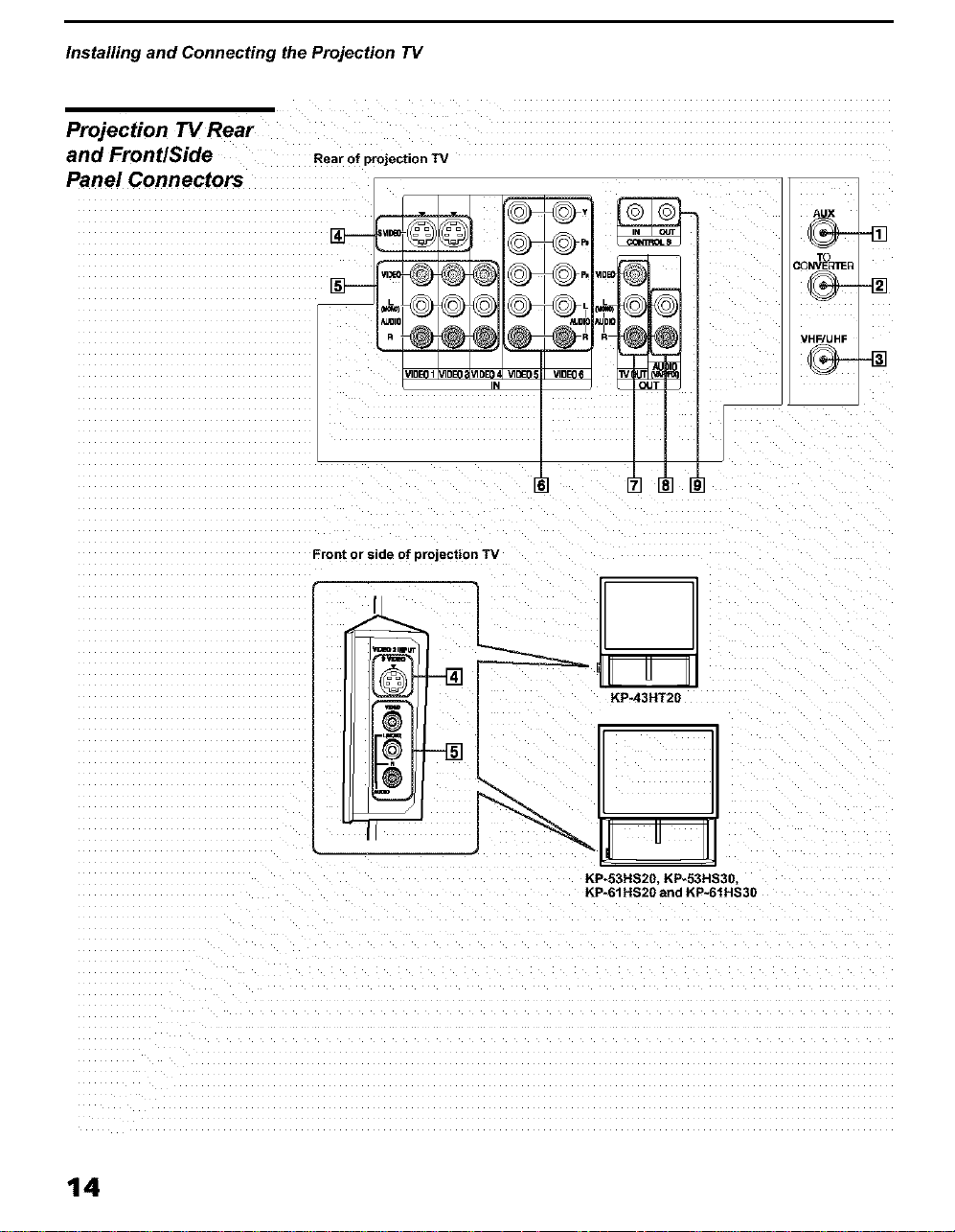
Installing and Connecting the Projection TV
Projection TV Rear
and FrontlSide
Rear of projection TV
Panel Connectors
@
AUX
DONVE_IIE_
@
_DE0 VIDE0!
IN
KP*53HS20, KP-53HS30,
KP-61HS20and KP-61HS30
VHF/UHF
14
Installing and Connecting the Projection TV
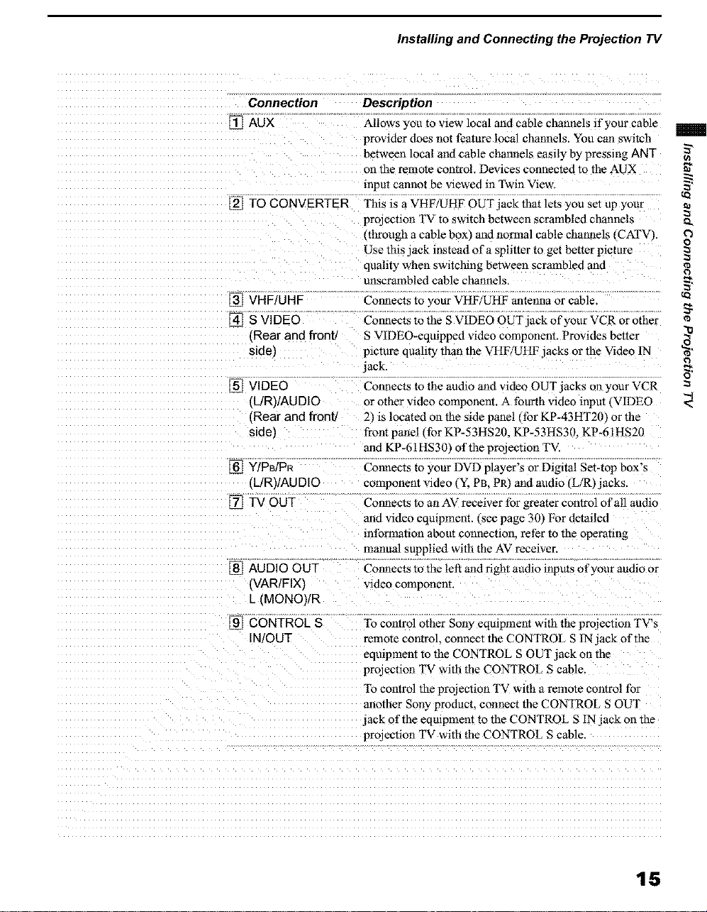
Connection Description
[] AUX Allows you to view local and cable channels if your cable
provider does not feature local channels. You can switch
between local and cable channels easily by pressing ANT
on the remote control. Devices connected to the AUX
input cannot be viewed in Twin View.
[] TO CONVERTER TNs is a VHF/UHF OUT jack that lets you set up your
projection TV to switch between scrambled channels
(through a cable box_ and normal cable channels (CXFV).
Use this-ack instead ofa sphtter to get better picture
quality when switching between scrambled and
unscrambled cable channels.
[] VHF/UHF Cormects to your VHF/UHF antenna or cable
[] S VIDEO Connects to the S VIDEO OUT jack of your VCR or other
(Rear and front/ S VlDEO*eqmpped video component. Provides better
side) pmture quahty than the VHF/UHF jacks or the Video IN
lack.
[] VIDEO Connects to the audio and video OUT jacks on your VCR
(L/R)/AU DID or other video component. A fourth video inpm _VIDEO
(Rear and front 21 is located on the side panel, for KP-43HT20 Jor the
sider front panel (for KP-53HS20. KP-53HS30. KP-61HS20
and KP-61HS30) of the projection TV.
[] Y/PB/PR Connects to your DVD player's or Digital Set-top box's
{L/R)/AU DIO component video _Y. PB. PR) and audio _L/R)jacks.
[] TV OUT Cormects to an AV receiver for greater control of all audio
and video eqmpment. €see page 30] For detailed
information about connecuolL refer to the operating
manual supplied with the AV receiver.
[] AUDIO OUT Connects to the left and right audio inputs of your audio or
{VAR/FIX) video component.
L (MONO)/R
[] CONTROL S
IN/OUT
"Io control other Sony eqmpment with the projection TV's
remote control, connect the CONTROL S IN jack of the
eqmpment to the CONTROL S OUT jack on the
projection TV with the CONTROL S cable.
"Ib control the projechon TV with a remote control for
another Sony product, connect the CONTROL S OUT
lack of the eqmpmem m the CONTROL S IN jack on the
prolection TV with the CONTROL S cable.
o,
o
@
g}
r}
o_
15
Installing and Connecting the Projection TV
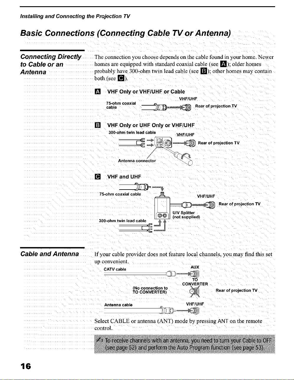
Basic Connections (Connecting Cable TV or Antenna)
Connecting Directly The connection you choose depends on the cable found in your home. Newer
to Cable or an homes are eqmpped with standard coaxial cable (sec In); oldcr homes
Antenna probably have 300-ohm twin lead cablc (sce r_); other homes may contain
both (see r_l),
[]
VHF Only or VHF/UHF or Cable
75-ohm coaxial
cabte __ Rear of projection TV
[] VHF Only or UHF Only or VHFIUHF
300-ohm twin lead cable
___ Rear of projection TV
Antenna connector
[] VHFand UHF
VHF!UHF
VHF/UHF
Cable and Antenna
75-ohm coaxial cab)e
_=_(_ Rear of projection TV
U/V Splitter
_Jn/VtSPutl_t;ied)
300-ohmtwinread ca_
If your cable provider does not feature local channels, you may find this set
up convenient.
CATV cable AUX
TO
(No connection to
TO CONVERTERI
Antenna cable VHF/UHF
Rear of projection TV
Select CABLE or antenna (ANT) mode by pressing ANT on the remote
control.
16
Installing and Connecting the Projection TV
Cable Box
Connections
Cable Box and Cable
This is the preferred basic cable TV hookup to use if:
_1 Your cable TV company scrambles some channels, but not all of them
tpay channels vs. regular cable channels) and you need to use a cable
box. and _"
You want to enjoy the Twin View feature.
With this setup you can:
Use the projection TV remote control to change channels using your
cable box when the signal is scrambled.
Ll Use the projection TV remote control to change channels using your ¢_
projection TV when the signal is not scrambled (Your projection TV's 5'
tuner provides a better signal than the cable box.
_l Use the Twin View feature, tWhnn all channels are routed through your ¢D
cable box. only one channel is sent to the projection TV. so you can nor
use the Twin View or Channel Index features for your cable box. ¢_'
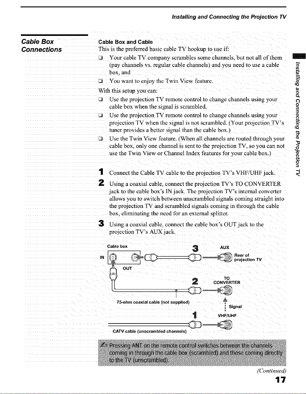
1 Connect the Cable TV cable to the projection TV's VHF/UHF jack.
2 Using a coaxial cable, connect the projection TV's TO CONVERTER
jack to the cable box's IN jack. The projection TV's internal converter
allows you to switch between unscrambled signals cnn£mg straight into
the projection TV and scrambled signals coming in through the cable
box. eliminating the need for an external splitter,
3 Using a coaxial cable, connect the cable box's OUT jack to the
projection TV's AUX jack.
o
o
¢)
Cable box
IN
OUT 2 ro
75-ohm coaxial cable (not supplied) A
CATV cable (unscrambled channels)
__ projection TV
3 Aux
Rear of
CONVERTER
_ Signal
VHF/UHF
(Continued)
17
Installing and Connecting the Projection TV
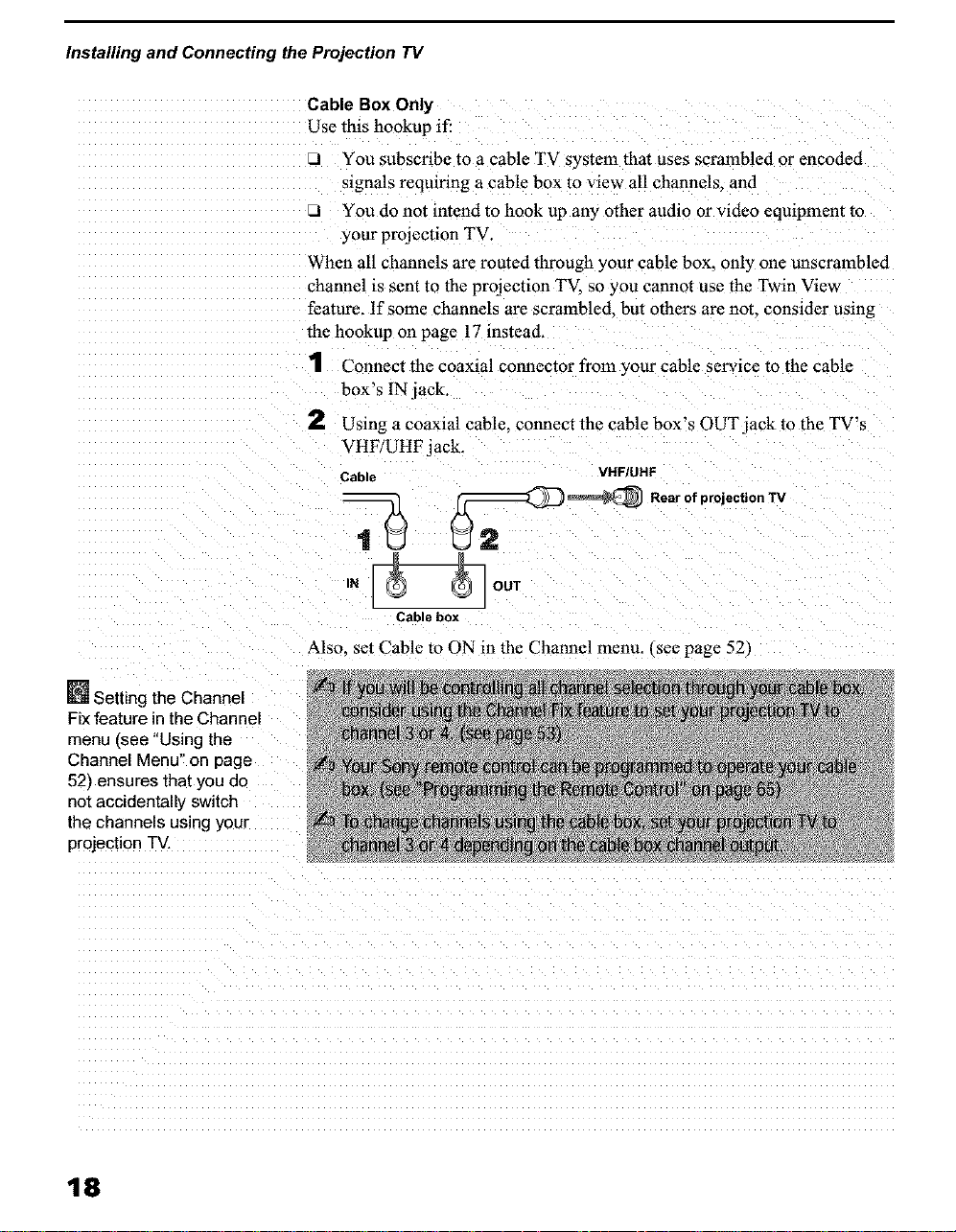
Cable Box Only
Use this hookup if:
LI You subscribe to a cable TV system that uses scrambled or encoded
signals requiring a cable box to view all channels, and
J You do not intend to hook up any other audio or video equipment to
your projection TV.
When all channels are routed through your cable box. only one unscrambled
channel is sent to the projection TV so you cannot use the Twin View
feature. If some channels are scrambled, but others are not. consider using
the hookup on page 17 instead.
1 Connect the coaxial connector from your cable service to the cable
box's IN jack,
2 Usingacoaxialcable, connectthecablebox'sOUTjacktotheTV's
VHF/UHF jack.
Cable VHFIUHF
,_ __ RearofprojectionTV
N _ OUT
Cable box
Also. set Cable to ON in the Channel menu. (see page 52)
_J_Setting the Channel
Fix feature in the Channel
menu (see "Using the
Channel Menu" on page
52/ensures that you do
not accidentally switch
the channels using your
projection TV,
18
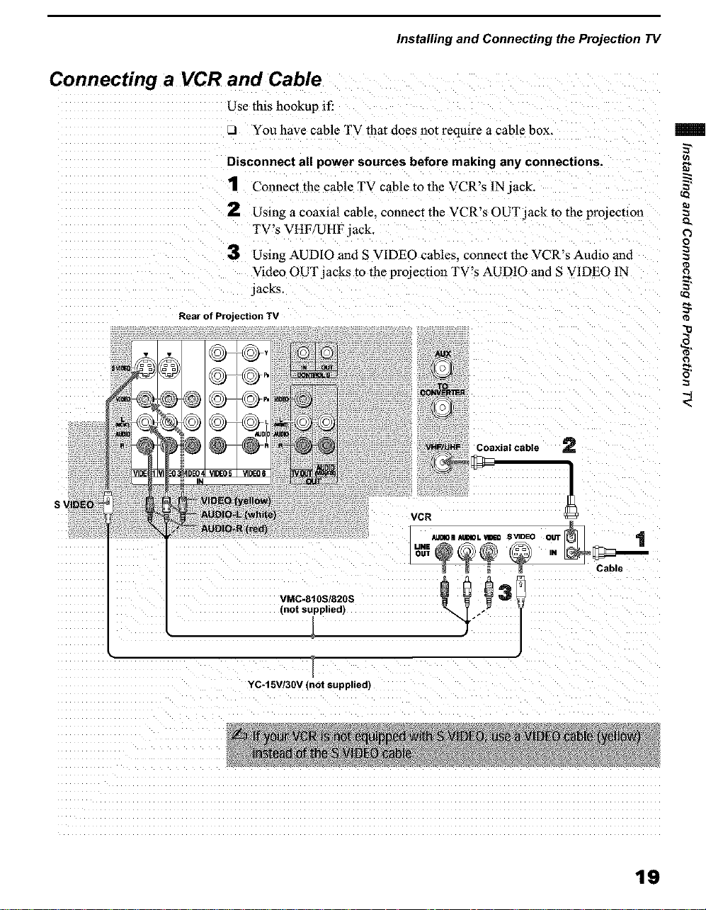
Connecting a VCR and Cable
Use this hookup if:
7..I You have cable TV that does not require a cable box.
Disconnect all power sources before making any connections.
1 Connect the cable TV cable to the VCR's IN jack.
Installing and Connecting the Projection TV
S 1
2 Using a coaxial cable, connect the VCR's OUT jack to the projecuon
TV's VHF/UHF jack.
3 Using AUDIO and S VIDEO cables, connect the VCR's Audio and
Video OUT jacks to the projection TV's AUDIO and S VIDEO IN
jacks.
Rear of Projection TV
Q.
o
0
[_xia I cable 2
VCR
• Jn4On xtmloL vmEo s _DEO OUt"r_
UNE N _
VMC-810S/820S
(not supplied)
YC-15V/30V (not supplied)
19
Installing and Connecting the Projection TV
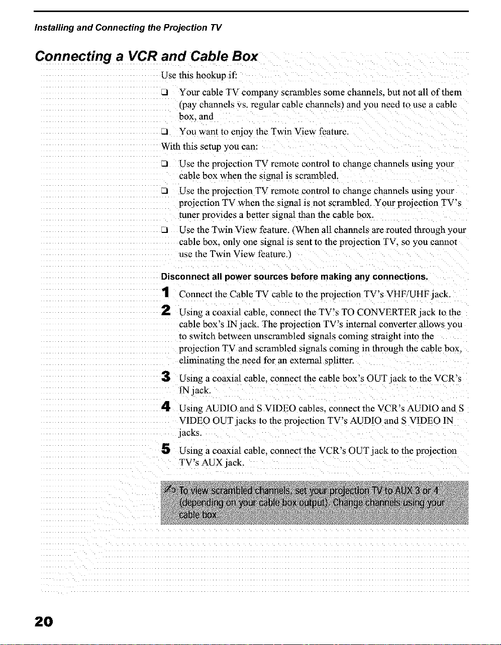
Connecting a VCR and Cable Box
Use this hookup if:
Your cable TV company scrambles some channels, but not all of them
(pay channels vs. regular cable channels) and you need to use a cable
box_ and
LI You want to enjoy the Twin View feature.
With this setup you can:
_1 Use the projection TV remote control to change channels using your
cable box when the signal is scrambled.
_1 Use the projection TV remote control to change channels using your
projection TV when the signal is not scrambled. Your projection TV's
tuner provides a beirut signal than the cable box.
Use the Twin View feature., When all channels are routed through your
cable box. only one signal is sent to the projection TV. so you cannm
use the Twin View feature,
Disconnect all power sources before making any connections.
1 Connect the Cable TV cable to the projection TV's VHF/UHF jack.
2
Using a coaxial cable, connect the TV's TO CONVERTER jack to the
cable box's 1Njack. The projection TV's internal converter allows you
to switch between unscranabled signals coming straight into the
projection TV and scrambled signals coming in through the cable box.
eliminating the need for an external splitter.
3
Using a coaxial cable, connect the cable box's OUT jack to the VCR's
IN jack.
4
Using AUDIO and S VIDEO cables, connect the VCR's AUDIO and S
VIDEO OUT jacks to the projection TV's AUDIO and S V1DEO IN
jacks.
5 Using a coaxial cable, connect the VCR's 0UTjack to the projection
TV's AUX jack.
2O
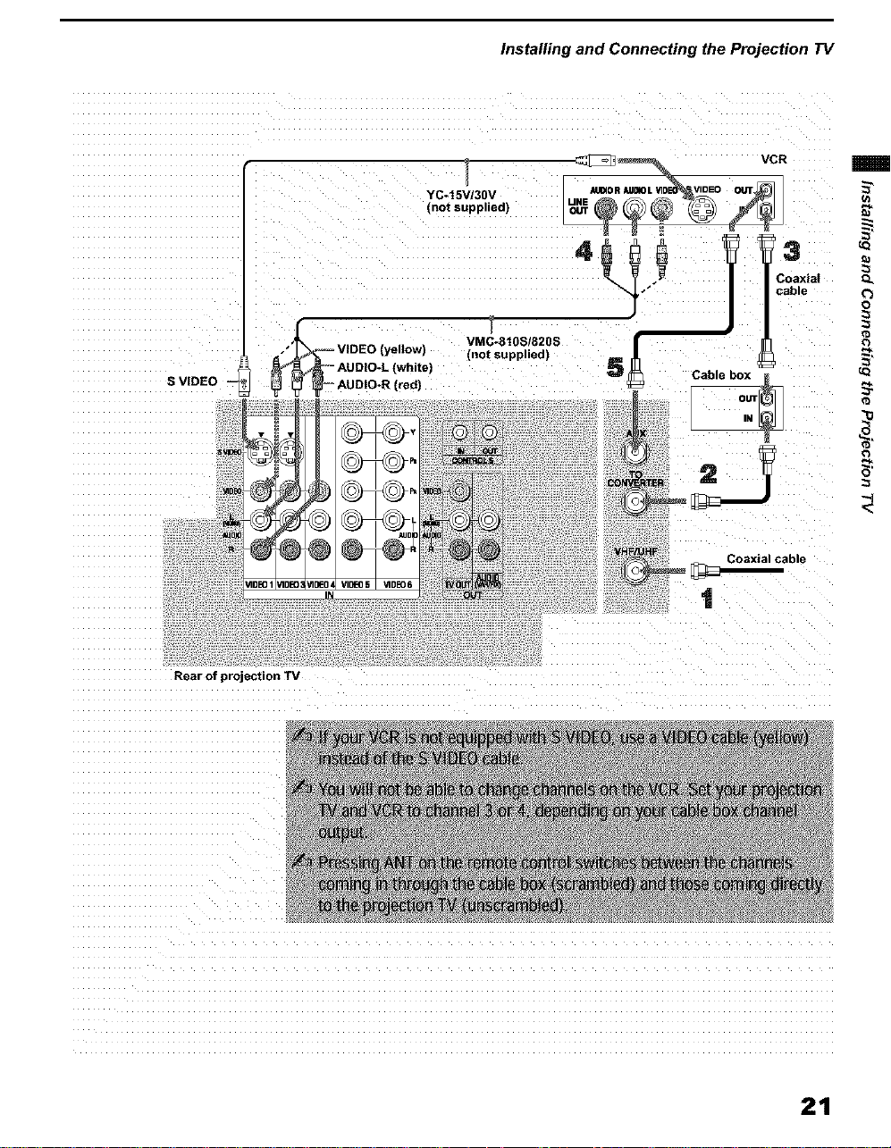
Installing and Connecting the Projection TV
VCR
S VIDEO
Rear of projection TV
I _-- AUDIO-L (white)
,'_-- VIDEO (yeltow)
/1DE04VID£*05 VIDE06
IN
YC-t5V/30V
(not supplied)
VMC-810S/820S
(not supplied)
_n
13
Coaxial Q.
cable ('_
0
t
21
Installing and Connecting the Projection TV
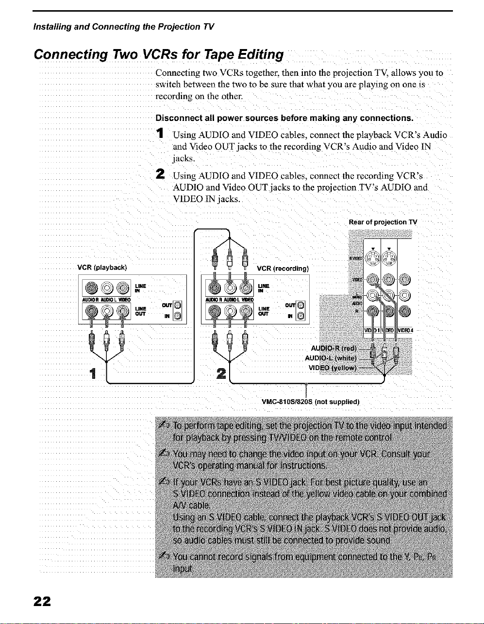
Connecting Two VCRs for Tape Editing
Connecting two VCRs together, then into the prqiection TV, allows you re
switch between the two to be sure that what you are playing on one is
recording on the other.
Disconnect all power sources before making any connections.
1 Using AUDIO and VIDEO cables_ connect the playback VCR's Audio
and Video OUT jacks to the recoMing VCR's Audio and Video IN
jacks.
2 Using AUDIO and VIDEO cables, connect the recording VCR's
AUDIO and Video OUT jacks to the projection TV's AUD10 and
VIDEO 1N jacks.
VCR (playback)
D®],u.,
AUDIO R AU_OL _IDEO
UNE OUT
OUT IN
AUDIOR ALIDIOL "dIDEO
Rear of projection TV
22
VMC-810SI820S (not supplied)
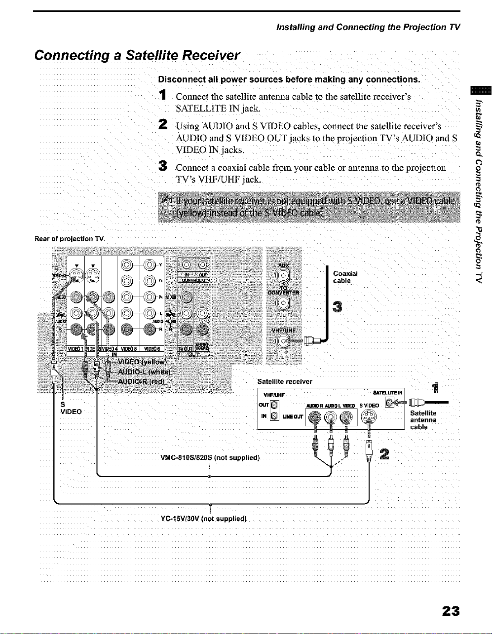
Connecting a Satellite Receiver
Disconnect all power sources before making any connections.
1 Connect the satellite antenna cable to the satellite receiver's
SATELLITE IN jack.
2 Using AUDIO and S VIDEO cables, connect thc satellite receiver's
AUDIO and S VIDEO OUT/acks to the projection TV's AUDIO and S
VIDEO 1N jacks.
3 Connect a coaxial cable from your cable or antenna to the projection
TV's VHF/UHF jack.
Rear of projection TV
Installing and Connecting the Projection TV
°i¸ 3
Q.
o
=
7,
- I
r
YC-t 5V/30V Inot supplied)
Satellite receiver
iN UMOUT Satellite
_ _ cable
o°ton°a
23
Installing and Connecting the Projection TV
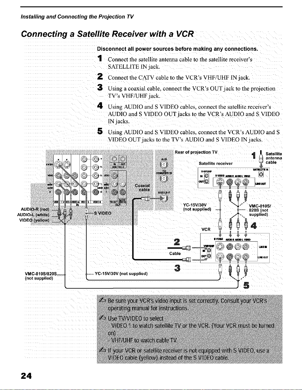
Connecting a Satellite Receiver with a VCR
Disconnect all power sources before making any connections.
1 Connect the satellite antenna cable to the satellite receiver's
SATELLITE IN jack.
2 Connect the CATV cable to the VCR's VHF/UHF IN jack.
3 Using a coaxial cable, connect the VCR's 0UTjack to the projection
TV's VHF/UHF jack.
4 Using AUDIO and S VIDE0 cables, connect thc satcllite receiver's
AUDIO and S VIDEO OUT jacks to the VCR's AUDIO and S VIDEO
IN jacks,
5 Using AUDIO and S VIDEO cables, connect the VCR's AUDIO and S
VIDEO OUT jacks to the TV's AUDIO and S VIDEO ]N jacks.
Rear of projection TV t _1 Satellite
Satellite receivel _ t]enna
VMC*810S/820S.--
(not supplied)
24
 Loading...