

Sony KLV-32BX320, KLV-32BX321, KLV-32BX323, KLV-32BX325, KLV-37BX320 Service Manual
...
AZ2FM CHASSIS
Segment: P-2F
SERVICE MANUAL
Version Date Subject
1.0 12/2010 Original manual issue.
LCD Digital Color TV
9-888-380-01
KLV-26/32/37/40BX320,321,323,325,420,421,423,425(CH)
2
MODEL LIST
MODEL COLOR COMMANDER DEST.MODEL COLOR COMMANDER DEST.
KLV-26BX320 Black RM-SA020 China
KLV-32BX320 Black RM-SA020 China
KLV-32BX321 Black/Black RM-SA020 China
KLV-32BX323 Black/Brown RM-SA020 China
KLV-32BX325 Black/Gun Metallic RM-SA020 China
KLV-37BX320 Black RM-SA020 China
KLV-40BX420 Black RM-SA020 China
KLV-40BX421 Black/Black RM-SA020 China
KLV-40BX423 Black/Brown RM-SA020 China
KLV-40BX425 Black/Gun Metallic RM-SA020 China

KLV-26/32/37/40BX320,321,323,325,420,421,423,425(CH)
3
WARNINGS AND CAUTIONS -ENGLISH
CAUTION
These servicing instructions are for use by qualified service personnel only.
To reduce the risk of electric shock, do not perform any servicing other than that contained in the operating instructions unless you are qualified to do so.
WARNING!!
An isolation transformer should be used during any service to avoid possible shock hazard, because of live chassis.
The chassis of this receiver is directly connected to the ac power line.
CARRYING THE TV
Be sure to follow these guidelines to protect your property and avoid causing serious injury.
• Carry the TV with an adequate number of people; larger size TVs require two or more people.
• Correct hand placement while carrying the TV is very important for safety and to avoid damages.
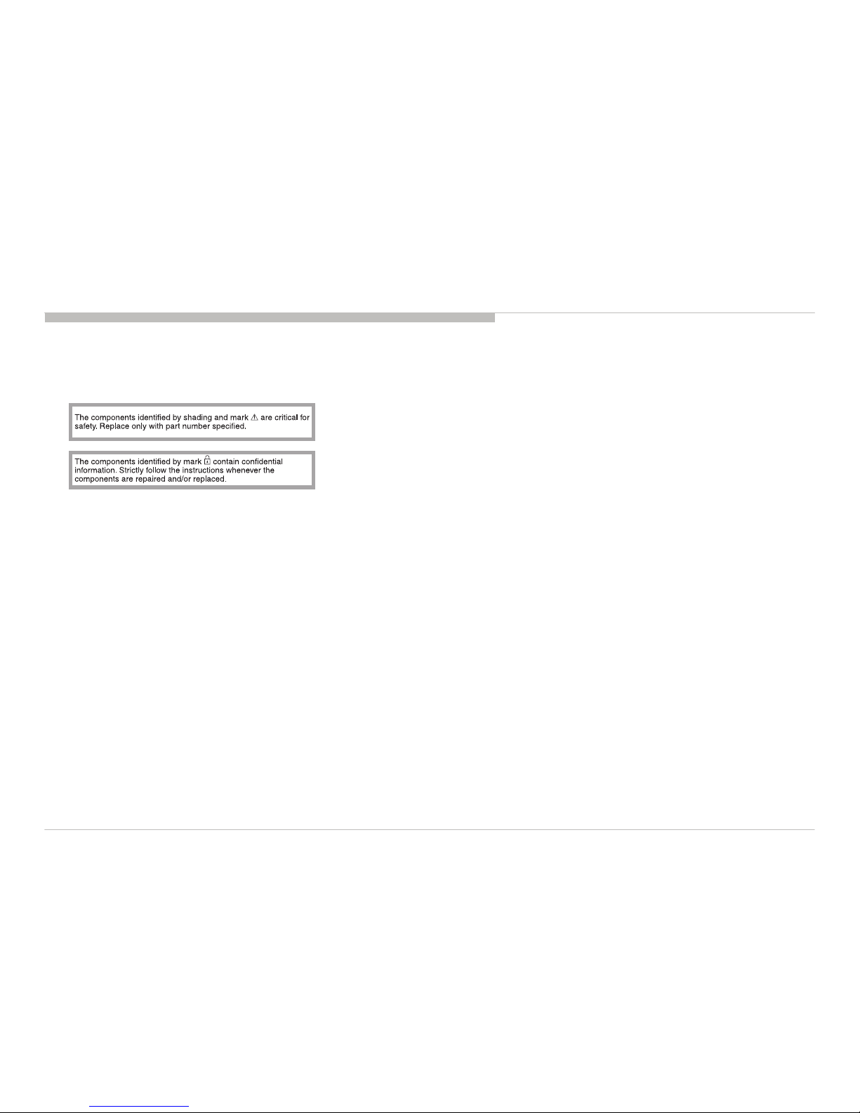
SAFETY-RELATED COMPONENT WARNING!!
Components identified by shading and ! mark on the schematic diagrams, exploded views, and in the parts list are critical for safe operation. Replace these components with Sony
parts whose part numbers appear as shown in this manual or in supplements published by Sony. Circuit adjustments that are critical for safe operation are identified in this manual.
Follow these procedures whenever critical components are replaced or improper operation is suspected.
KLV-26/32/37/40BX320,321,323,325,420,421,423,425(CH)
4
WARNINGS AND CAUTIONS
USE CAUTION WHEN HANDLING THE LCD PANEL
When repairing the LCD panel, be sure you are grounded by using a wrist band.
When repairing the LCD panel on the wall, the LCD panel must be secured using the 4 mounting holes on the rear cover.
1) Do not press on the panel or frame edge to avoid the risk of electric shock.
2) Do not scratch or press on the panel with any sharp objects.
3) Do not leave the module in high temperatures or in areas of high humidity for an extended period of time.
4) Do not expose the LCD panel to direct sunlight.
5) Avoid contact with water. It may cause a short circuit within the module.
6) Disconnect the AC power when replacing the backlight (CCFL) or inverter circuit. (High voltage occurs at the inverter circuit at 650Vrms.)
7) Always clean the LCD panel with a soft cloth material.
8) Use care when handling the wires or connectors of the inverter circuit. Damaging the wires may cause a short.
9) Protect the panel from ESD to avoid damaging the electronic circuit (C-MOS).
10) It is recommended not to exceed 1 hour of Power-On nor Burn-in period with LCD panel face down condition, in repair activity.

KLV-26/32/37/40BX320,321,323,325,420,421,423,425(CH)
5
SAFETY CHECK-OUT
After correcting the original service problem, perform the following safety checks before releasing the set to the customer:
1. Check the area of your repair for unsoldered or poorly soldered connections. Check the entire board surface for solder splashes and bridges.
2. Check the interboard wiring to ensure that no wires are “pinched” or touching high-wattage resistors.
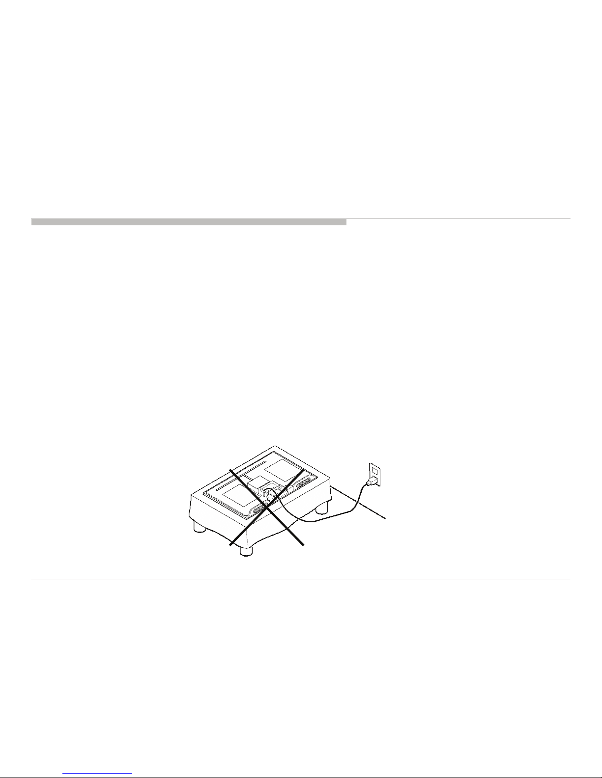
3. Check that all control knobs, shields, covers, ground straps, and mounting hardware have been replaced. Be absolutely certain that you have replaced all the insulators.
4. Look for unauthorized replacement parts, particularly transistors, that were installed during a previous repair. Point them out to the customer and recommend their replacement.
5. Look for parts which, though functioning, show obvious signs of deterioration. Point them out to the customer and recommend their replacement.
6. Check the line cords for cracks and abrasion. Recommend the replacement of any such line cord to the customer.
7. Check the antenna terminals, metal trim, “metallized” knobs, screws, and all other exposed metal parts for AC leakage. Check leakage as described below.
8. For safety reasons, repairing the Power board and/or Inverter board is prohibited.
KLV-26/32/37/40BX320,321,323,325,420,421,423,425(CH)
6
SAFETY CHECK-OUT
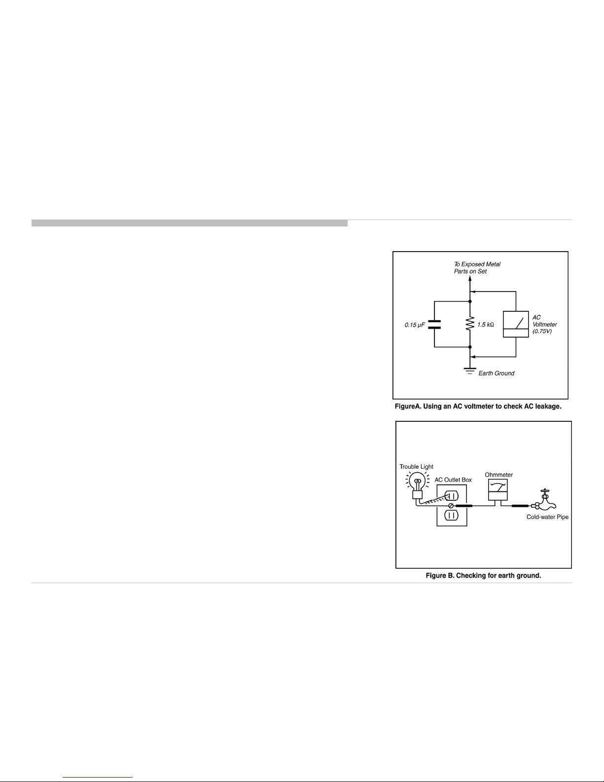
Leakage Test
The AC leakage from any exposed metal part to earth ground and from all exposed metal parts to any exposed
metal part having a return to chassis, must not exceed 0.5 mA (500 microamperes).
Leakage current can be measured by any one of three methods.
1. A commercial leakage tester, such as the Simpson 229 or RCA WT-540A. Follow the manufacturers’
instructions to use these instructions.
2. A battery-operated AC milliampmeter. The Data Precision 245 digital multimeter is suitable for this job.
3. Measuring the voltage drop across a resistor by means of a VOM or battery-operated AC voltmeter. The
“limit” indication is 0.75 V, so analog meters must have an accurate low voltage scale.
The Simpson’s 250 and Sanwa SH-63TRD are examples of passive VOMs that are suitable. Nearly all
battery-operated digital multimeters that have a 2 VAC range are suitable (see Figure A).
How to Find a Good Earth Ground
A cold-water pipe is a guaranteed earth ground; the cover-plate retaining screw on most AC outlet boxes is also
at earth ground.
If the retaining screw is to be used as your earth ground, verify that it is at ground by measuring the resistance
between it and a cold-water pipe with an ohmmeter. The reading should be zero ohms.
If a cold-water pipe is not accessible, connect a 60- to 100-watt trouble- light (not a neon lamp) between the hot
side of the receptacle and the retaining screw. Try both slots, if necessary, to locate the hot side on the line; the
lamp should light at normal brilliance if the screw is at ground potential (see Figure B).
KLV-26/32/37/40BX320,321,323,325,420,421,423,425(CH)
7
SELF DIAGNOSIS FUNCTION
DIAGNOSTIC TEST INDICATORS
When an error occurs, the STANDBY LED will flash a set number of times to
indicate the possible cause of the problem.
If there is more than one error, the LED will identify the first of the problem areas.
Result for all of the following diagnostic items are displayed on screen.
If the screen displays a “0”, no error has occurred .
The units in this manual contain a self-diagnostic function. If an error occurs, the STANDBY LED will automatically begin to flash.
The number of times the LED flashes translates to a probable source of the problem.
A definition of the STANDBY LED flash indicators is listed in the instruction manual for the user’s knowledge and reference.
If an error symptom cannot be reproduced, the remote commander can be used to review the failure occurrence data stored in memory to reveal past problems and how often these
problems occur.
STBY LED
Fla sh tim e
Se rvic e me nu Item na m e
(Screeen Dsisplay)
Diagnostic Item Des cr iption
6Inverter_ERR
When The connection to the Inverter board
is not proper, or the inverter board has
som ething wrong.("Inverter_ERR")
8AU PROT
When the connections of the s peaker has
DC level d iffe re nc e("AU P ROT") Or Mai n
Am p has the Over Current or High
temperature status ("Amp_ERR").

KLV-26/32/37/40BX320,321,323,325,420,421,423,425(CH)
8
SELF DIAGNOSIS FUNCTION
DISPLAY OF STANDBY LED FLASH COUNT
SELF-DIAGNOSTIC SCREEN DISPLAY
For errors with symptoms such as “power sometimes shuts off” or “screen sometimes goes out” that cannot be confirmed, it is possible to bring up past occurrences of failure for
confirmation on the screen:
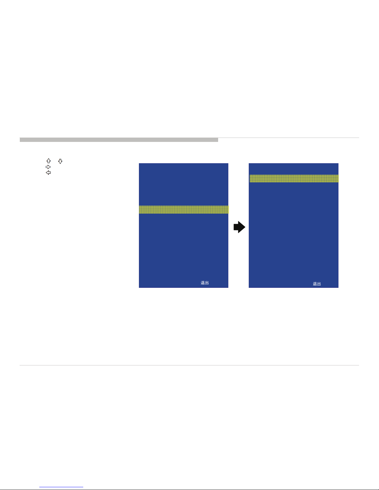
[To Bring Up Screen Test]
In standby mode, press buttons on the remote commander sequentially in rapid succession as shown below:
Note: The screen display of SELF-DIAGNOSIC SCREEN DISPLAY confirms from factory menu.
[How to use the remote commander]
< >Execute
< > / < >Data change
< > / < >Menu up/down
<Display><5><Vol Up><Power>Factory mode on
The flow of controlFunction
6 times
8 times
LED ON sec.
LED OFF sec.
LED OFF
sec.
[ FLASH COUNT ]
0.3
0.3
2
5
DISPLAY TV POWERChannel Volume
KLV-26/32/37/40BX320,321,323,325,420,421,423,425(CH)
9
SELF DIAGNOSIS FUNCTION
[SELF DIAGNOSTIC SCREEN DISPLAY]
a) Press / to select “SELF DIAGNOSIS”.
b) Press to enter the menu.
c) Press to returned “FACTORY MENU”.
WHITE BALANCE
COLOR TEMP
SELF DIAGNOSIS
ADC ADJ
AGING MODE
FACTORY RESET
EDID WP
RECALL DATA
PANEL INDEX
RANGE SCAN
SAVE
SERVICE MODE
INPUT SOURCE
FACTORY MENU
>>
>>
>>
>>
OFF
OFF
ON
OFF
WXGA CMO26
OFF
OFF
>>
ATV
:MENU
AUDIO ERROR
INVERTER ERROR
BACK
SELF DIAGNOSIS
0
0
<<
:MENU
[Exiting the Self-diagnostic screen]
To exit the Self Diagnostic screen, turn off the power to the TV by pressing the POWER button on the remote or the POWER button on the TV.
KLV-26/32/37/40BX320,321,323,325,420,421,423,425(CH)
10
SEC 1. DISASSEMBLY AND PART LIST
• Items with no part number and no description are not stocked because they are seldom required for roution service.
• The construction parts of an assembled part are indicated with a collation number in the remark colum.
• Items marked " * " are not stocked since they are seldom required for routine service. Some delay should be anticipated when ordering these items.
 Loading...