

Sony KLV-26U300A, KLV-32U300A, RM-CA009, RM-GA009, KLV-37U300A Service Manual
SERVICE MANUAL
LCD Colour TV
LAX U CHASSIS
MODEL NAME REMOTE COMMANDER DESTINATION
KLV-26U300A
RM-GA009 E/ME/OCE/SA
KLV-26U300A
RM-CA009 WB
KLV-32U300A
RM-GA009 E/ME/OCE/SA
KLV-32U300A
RM-CA009 WB
ORIGINAL MANUAL ISSUE DATE: 6/2007
REVISION DATE SUBJECT
7/2007 Added KLV-26U300A and KLV-37U300A models.
8/2007 Added Taiwan model.
9-834-174-03
HISTORY INFORMATION FOR THE FOLLOWING MANUAL:
MODEL NAME REMOTE COMMANDER DESTINATION
KLV-37U300A
RM-GA009 E/ME/OCE/SA
KLV-37U300A
RM-CA009 WB

SERVICE MANUAL
LCD Colour TV
LAX U CHASSIS
9-834-174-03
KLV-26U300A/32U300A/37U300A RM-GA009
(E/ME/OCE/SA)
MODEL NAME REMOTE COMMANDER DESTINATION
KLV-26U300A
RM-GA009 E/ME/OCE/SA
KLV-26U300A
RM-CA009 WB
KLV-32U300A
RM-GA009 E/ME/OCE/SA
KLV-32U300A
RM-CA009 WB
MODEL NAME REMOTE COMMANDER DESTINATION
KLV-37U300A
RM-GA009 E/ME/OCE/SA
KLV-37U300A
RM-CA009 WB
RM-CA009
(WB)

KLV-26/32/37U300A2
TABLE OF CONTENTS :
SPECIFICATIONS 3
WARNINGS AND CAUTIONS 6
SAFETY-RELATED COMPONENT WARNING 7
SAFETY CHECK-OUT 9
SECTION 1 : DISASSEMBLY 10
SECTION 2 : SERVICE MODE (factory mode) 16
SECTION 3 : ADJUSTMENT 18
3-1. Preparation 18
3-2. Adjust White Balance of "COOL" temperature; 18
3-3. Adjust White Balance of "NEUTRAL" temperature; 18
3-4. Adjust White Balance of "WARM" temperature; 18
3-5. Average Value of W/B 18
SECTION 4 : TIMING CHART 19
SECTION 5 : DIAGRAMS 20
5-1. BOARD Layout/WIRING Layout 20
5-1-1. KLV-26U300A 20
5-1-2. KLV-32U300A 21
5-1-3. KLV-37U300A 22
5-2. Frame Diagram 23
5-3. BLOCK DIAGRAM 24
5-4. SCHEMATIC 25
5-5. PCB Layout 45
SECTION 6 : EXPLODED VIEW & REPLACEMENT PARTS LIST 51
6-1. KLV-26U300A 51
6-1-1. BEZEL AND REAR COVER 51
6-1-2. CHASSIS 52
6-1-3. PARTS LIST 53
(1) Except WB model 53
(2) WB model 54
6-2. KLV-32U300A 55
6-2-1. BEZEL AND REAR COVER 55
6-2-2. CHASSIS 56
6-2-3. PARTS LIST 57
(1) Except WB model 57
(2) WB model 58
6-3. KLV-37U300A 59
6-3-1. BEZEL AND REAR COVER 59
6-3-2. CHASSIS 60
6-3-3. PARTS LIST 61
(1) Except WB model 61
(2) WB model 62
3 KLV-26/32/37U300A
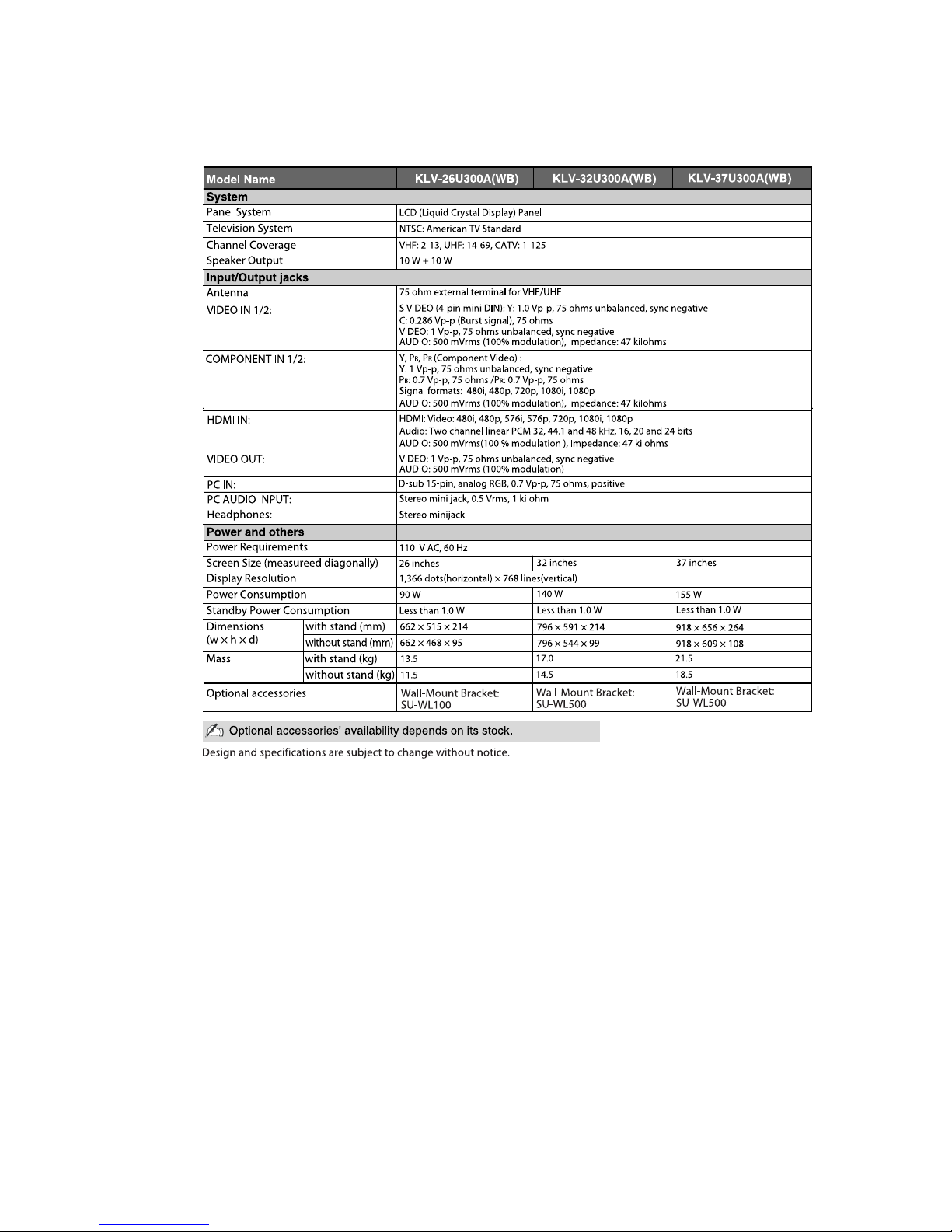
SPECIFICATIONS :
* Dimensions and mass are approximate values.
Design and specifications are subject to change without notice.
Model name KLV-37U300A KLV-32U300A KLV-26U300A
System
Panel System LCD (Liquid Crystal Display) Panel
TV System B/G, I, D/K, M
Colour System PAL, PAL60 (only Video In), SECAM, NTSC4.43 (only Video In), NTSC3.58
Channel Coverage B/G: VHF: E2 to E12/ UHF: E21 to E69/ CATV: S01 to S03, S1 to S41
VHF: 0 to 12, 5A, 9A/ UHF: 28 to 69/ CATV: S01 to S03, S1 to S44
(Australia only)
VHF: 1 to 11/ UHF: 21 to 69/ CATV: S01 to S03, S1 to S41 (New Zealand only)
I: UHF: B21 to B69/ CATV: S01 to S03, S1 to S41
D/K: VHF: C1 to C12, R1 to R12/ UHF: C13 to C57, R21 to R60/
CATV: S01 to S03, S1 to S41, Z1 to Z39
M: VHF: A2 to A13/ UHF: A14 to A79/ CATV: A-8 to A-2, A to W+4, W+6 to W+84
Sound Output 10 W + 10 W
Input/Output jacks
Antenna 75 ohm external terminal
1, 2
S video input (4-pin mini DIN)
Y: 1.0 Vp-p, 75 ohms unbalanced/C: 0.286 Vp-p (Burst signal), 75 ohms
1, 2 Video input (phono jacks): 1 Vp-p, 75 ohms unbalanced, sync negative
1, 2 Audio input (phono jacks): 500 mVrms, Impedance: 47 kilohms
1, 2
Component input (phone jacks)
Supported formats: 1080p, 1080i, 720p, 576p, 576i, 480p, 480i
Y: 1 Vp-p, 75 ohms, 0.3V sync negative/P
B/CB
: 0.7 Vp-p, 75 ohms/PR/CR: 0.7
Vp-p, 75 ohms
1, 2 Audio input (phono jacks): 500 mVrms, Impedance: 47 kilohms
Video output (phono jack): 1 Vp-p, 75 ohms unbalanced, sync negative
Audio output (phono jacks): 500 mVrms (100% modulation)
HDMI IN Video: 1080p, 1080i, 720p, 576p, 576i, 480p, 480i
Audio: Two channel linear PCM 32, 44.1 and 48 kHz, 16, 20 and 24 bits
Analogue audio input (phono jacks): 500 mVrms, Impedance: 47 kilohms
PC IN
(RGB)
PC Input (D-sub 15-pin)
G: 0.7 Vp-p, 75 ohms, non Sync on Green/B: 0.7 Vp-p, 75 ohms/
R: 0.7 Vp-p, 75 ohms/HD: 1-5 Vp-p/VD: 1-5 Vp-p
PC IN
PC audio input (minijack): 500 mVrms, Impedance: 47 kilohms
i
Headphones jack
Power and others
Power requirements 110-240 V AC, 50/60 Hz
Screen Size (inches) 37 32 26
Display Resolutiion 1,366 pixels (horizontal) × 768 lines (vertical)
Power Consumption Indicated on the rear of the TV.
Dimensions
(w × h × d) *
with stand (mm) 918 × 656 × 264 796 × 591 × 214 662 × 515 × 214
without stand (mm) 918 × 609 × 108 796 × 544 × 99 662 × 468 × 95
Mass * with stand (kg) 21.5 17.0 13.5
without stand (kg) 18.5 14.5 11.5
Optional Accessories SU-WL500 (for KLV-37U300A/KLV-32U300A)
SU-WL100 (for KLV-26U300A)
• Except WB model
4 KLV-26/32/37U300A
• WB model
5 KLV-26/32/37U300A
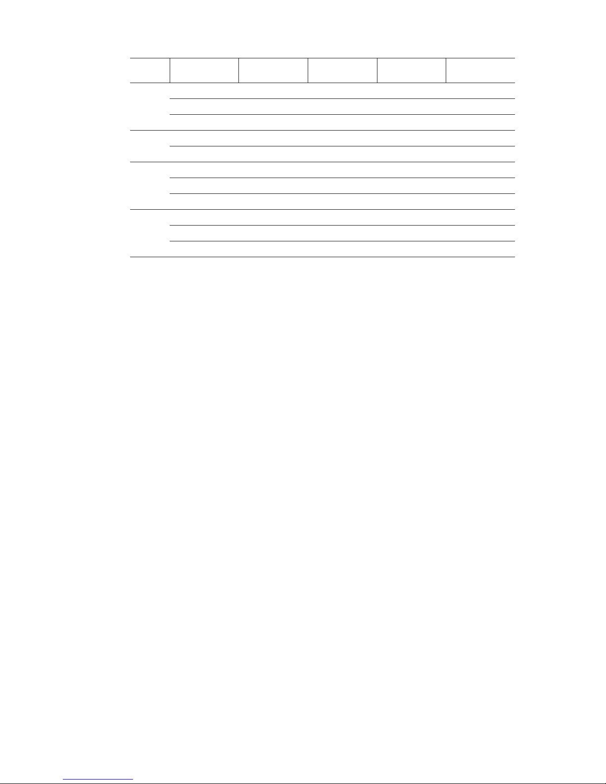
PC input signal Reference chart
This TV’s PC input does not support Sync on Green or Composite Sync.
This TV’s PC input does not support interlaced signals.
For the best picture quality, it is recommended to use the signals (boldfaced) in the above chart with a 60Hz
vertical frequency from a personal computer. In plug and play, signals with a 60Hz vertical frequency will be
selected automatically.
Signals
Horizontal
(Pixel)
Vertical (Line)
Horizontal
frequency (kHz)
Vertical
frequency (kHz)
Standard
VGA 640 480 31.5 60 VGA
640 480 37.5 75 VESA
720 400 31.5 70 VGA-T
SVGA 800 600 37.9 60 VESA Guidelines
800 600 46.9 75 VESA
XGA 1024 768 48.4 60 VESA Guidelines
1024 768 56.5 70 VESA
1024 768 60 75 VESA
WXGA 1280 768 47.4 60 VESA
1280 768 47.8 60 VESA
1360 768 47.7 60 VESA

6 KLV-26/32/37U300A
WARNINGS AND CAUTIONS
CAUTION
These servicing instructions are for use by qualified service personnel only. To reduce the risk of electric shock, do not perform any
servicing other than that contained in the operating instructions unless you are qualified to do so.
WARNING!!
An isolation transformer should be used during any service to avoid possible shock hazard, because of live chassis.The chassis of
this receiver is directly connected to the ac power line.
!
SAFETY-RELATED COMPONENT WARNING!!
Replace all components with Sony parts whose part numbers appear as shown in this manual or in supplements
published by Sony.
ATTENTION!!
Ces instructions de service sont à l’usage du personnel de service qualifié seulement. Pour prévenir le risque de choc électrique, ne
pas faire l’entretien autre que celui contenu dans le Mode d’emploi à moins que vous soyez qualifié faire ainsi.
Afin d’eviter tout risque d’electrocution provenant d’un chássis sous tension, un transformateur d’isolement doit etre utilisé lors de tout
dépannage. Le chássis de ce récepteur est directement raccordé à l’alimentation du secteur.
!
ATTENTION AUX COMPOSANTS RELATIFS A LA SECURITE!!
Remplacer tout les composants par des composants Sony dont le numero de piece est indique dans le present manuel ou dans des
supplements publies par Sony.
7 KLV-26/32/37U300A
SAFETY-RELATED COMPONENT WARNING
It is essential that all critical parts be replaced only with the part number specified in the electrical parts list to prevent electric shock,
fire, or other hazard.
NOTE: Do not modify the original design without obtaining written permission from the manufacturer or you will void the original parts and
labor guarantee.
USE CAUTION WHEN HANDLING THE LCD PANEL
When repairing the LCD panel, be sure you are grounded by using a wrist band.
To avoid damaging the LCD panel:
do not press on the panel or frame edge to avoid the risk of electric shock.
do not scratch or press on the panel with any sharp objects.
do not leave the module in high temperatures or in areas of high humidity for an extended period of time.
do not expose the LCD panel to direct sunlight.
avoid contact with water. It may cause a short circuit within the module.
disconnect the AC power when replacing the backlight (CCFL) or inverter circuit.
(High voltage occurs at the inverter circuit at 650Vrms.)
always clean the LCD panel with a soft cloth material.
use care when handling the wires or connectors of the inverter circuit. Damaging the wires may cause a short.
protect the panel from ESD to avoid damaging the electronic circuit (C-MOS).
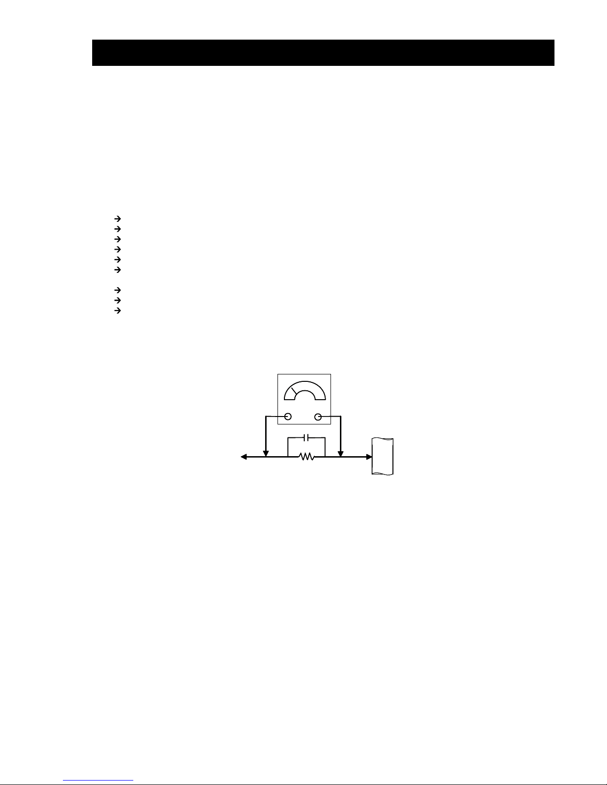
LEAKAGE CURRENT HOT CHECK CIRCUIT
AC Volt-meter
To Instruments
exposed
METALLIC PARTS
1.5 Kohm/10W
Good Earth Ground
Such as WATER PIPE,
CONDUIT etc.
8 KLV-26/32/37U300A
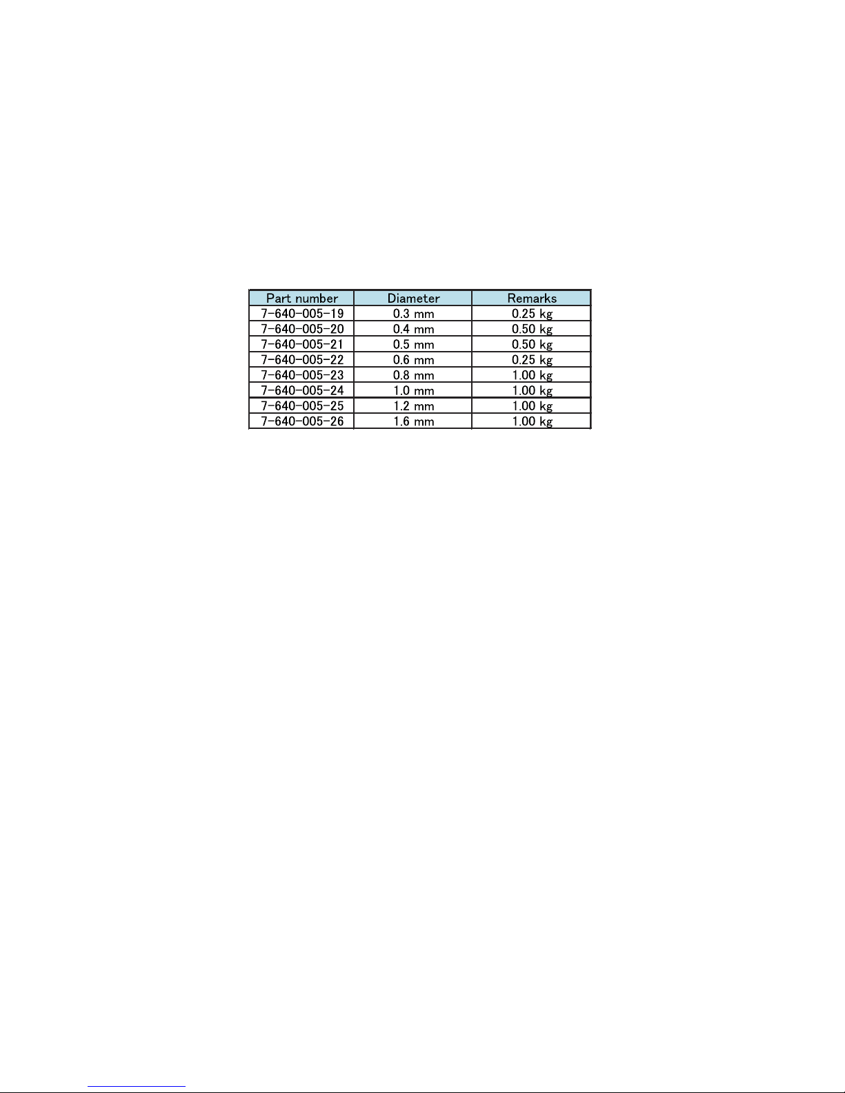
The circuit boards used in these models have been processed using
Lead Free Solder.
The servicing of these boards requires special precautions to be taken
as outlined below.
It is strongly recommended to use Lead Free Solder material in order to guarantee optimal quality of new solder joints.
Lead Free Solder is available under the following part numbers:
Due to the higher melting point of Lead Free Solder the soldering iron tip temperature needs to be set to 370 degrees centigrade.
This requires soldering equipment capable of accurate temperature control coupled with a good heat recovery characteristics.
For more information on the use of Lead Free Solder, please refer to http://www.sony-training.com
9 KLV-26/32/37U300A
SAFETY CHECK-OUT
After correcting the original service problem, perform the
following safety checks before releasing the set to the customer:
1. Check the area of your repair for unsoldered or poorly soldered connections. Check the entire board surface for solder
splashes and bridges.
2. Check the interboard wiring to ensure that no wires are
“pinched” or touching high-wattage resistors.
3. Check that all control knobs, shields, covers, ground straps,
and mounting hardware have been replaced. Be absolutely certain that you have replaced all the insulators.
4. Look for unauthorized replacement parts, particularly transistors, that were installed during a previous repair. Point them
out to the customer and recommend their replacement.
5. Look for parts which, though functioning, show obvious signs
of deterioration. Point them out to the customer and recommend their replacement.
6. Check the line cords for cracks and abrasion. Recommend the
replacement of any such line cord to the customer.
7. Check the antenna terminals, metal trim, “metallized” knobs,
screws, and all other exposed metal parts for AC leakage. Check
leakage as described below.
LeakageTest
The AC leakage from any exposed metal part to earth ground and
from all exposed metal parts to any exposed metal part having a
return to chassis, must not exceed 0.5 mA (500 microamperes).
Leakage current can be measured by any one of three methods.
1. A commercial leakage tester, such as the Simpson 229 or RCA
WT-540A. Follow the manufacturers’ instructions to use these
instructions.
2. A battery-operated AC milliampmeter. The Data Precision 245
digital multimeter is suitable for this job.
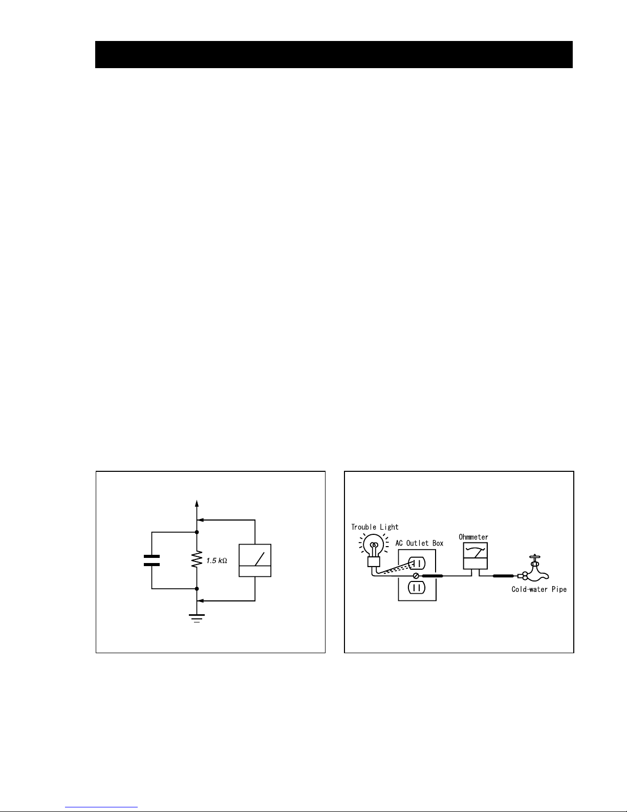
3. Measuring the voltage drop across a resistor by means of a
VOM or battery-operated AC voltmeter. The “limit” indication is 0.75V, so analog meters must have an accurate low voltage scale.
The Simpson’s 250 and Sanwa SH-63TRD are examples of
passive VOMs that are suitable. Nearly all battery-operated
digital multimeters that have a 2 VAC range are suitable (see
Figure A).
How to Find a Good Earth Ground
A cold-water pipe is a guaranteed earth ground; the cover-plate
retaining screw on most AC outlet boxes is also at earth ground. If
the retaining screw is to be used as your earth ground, verify that
it is at ground by measuring the resistance between it and a coldwater pipe with an ohmmeter. The reading should be zero ohms.
If a cold-water pipe is not accessible, connect a 60- to 100-watt
trouble- light (not a neon lamp) between the hot side of the
receptacle and the retaining screw. Try both slots, if necessary, to
locate the hot side on the line; the lamp should light at normal
brilliance if the screw is at ground potential (see Figure B).
To Exposed Metal
Par ts on Set
0.15
µ
F
Earth Ground
AC
Voltmeter
(0.75V)
Figure A. Usingan AC voltmeter to check AC leakage.
Figure B. Checking for earth ground.
KLV-26/32/37U300A10
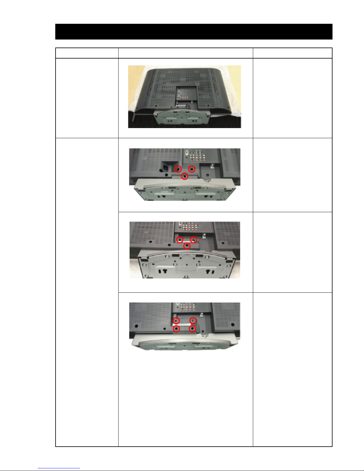
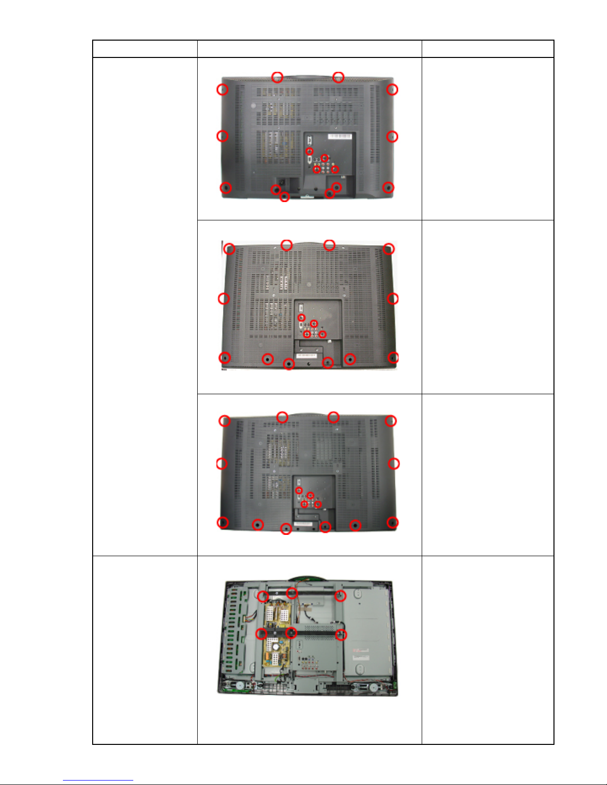
SECTION 1 : DISASSEMBLY
STEP PICTURE DESCRIPTION
Gently place the TV set
face down on the table.
KLV-26U300A:
Remove 3 screws to
release the Tabletop
Stand from the unit.
KLV-32U300A:
Remove 3 screws to
release the Tabletop
Stand from the unit.
KLV-37U300A:
Remove 4 screws to
release the Tabletop
Stand from the unit.
Service Position
Stand Removal
KLV-26/32/37U300A11
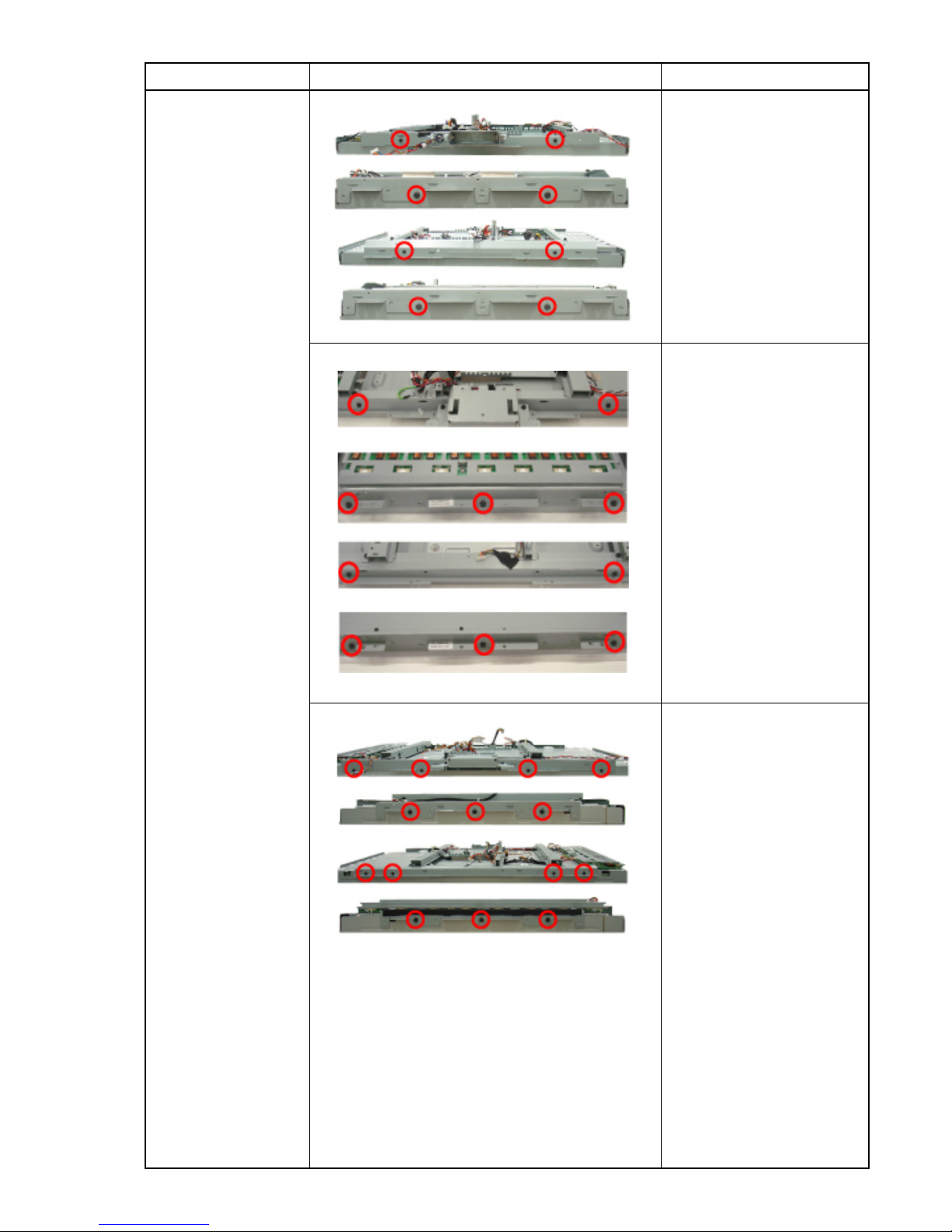
Rear Cover
Removal
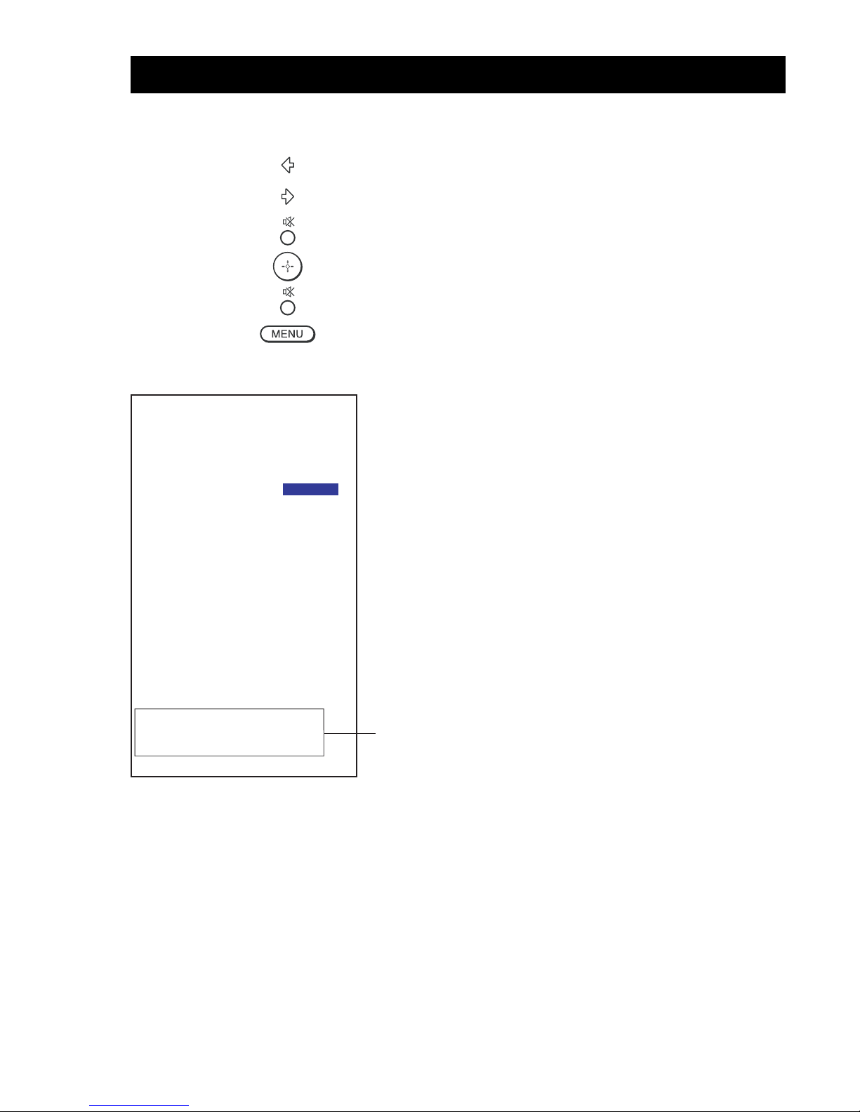
Wall Mount
Bracket
Removal
STEP PICTURE DESCRIPTION
KLV-26U300A:
Remove 16 screws to
release the rear cover.
KLV-32U300A:
Remove 16 screws to
release the rear cover.
KLV-37U300A:
Remove 16 screws to
release the rear cover.
Remove 6 screws to
release the Wall Mount
Bracket.
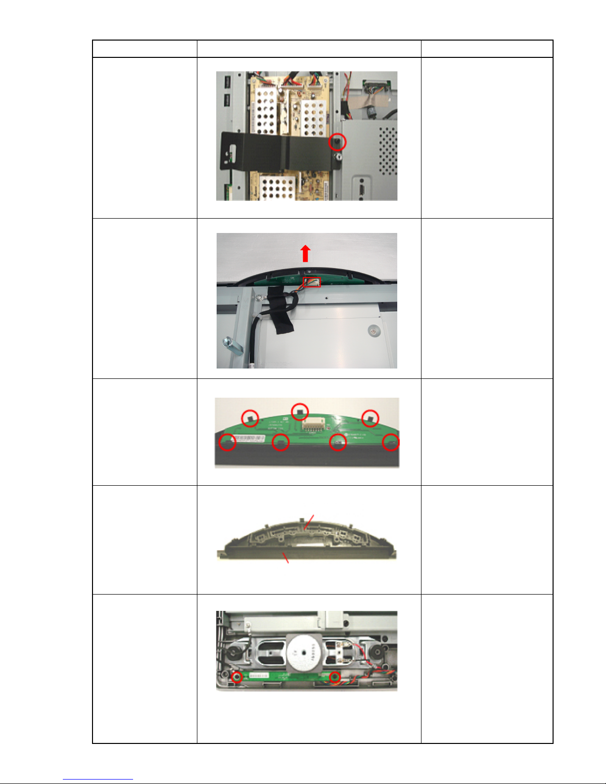
KLV-26/32/37U300A12
Cover Sheet
Removal
Botton ASSY
Removal
H1 Mount
Removal
Key Cover and
Multi Botton
Removal
H2 Mount
Removal
STEP PICTURE DESCRIPTION
Remove 1 screw to
release the Cover
Sheet.
Remove function cable
from function board
connector.
Bend key cover hooks
to release function
board.
Dismantle function key
form function key cover.
Remove 2 screws and
1 connector to release
the H2 Mount.
Multi Button
Function Key Cover
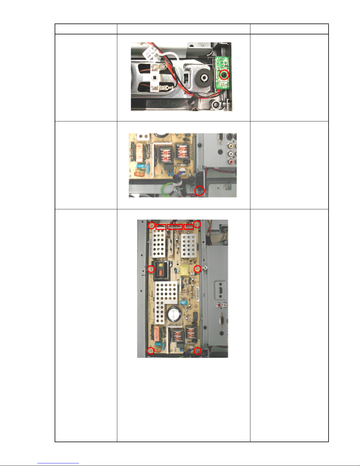
KLV-26/32/37U300A13
H3 Mount
Removal
AC Inlet Removal
G Mount Removal
STEP PICTURE DESCRIPTION
Remove 1 screw and
1 connector to release
the H3 Mount.
Remove 1 screw and
1 connector to release
the AC Inlet.
Remove 6 screws and
3 connectors to release
the G Mount.
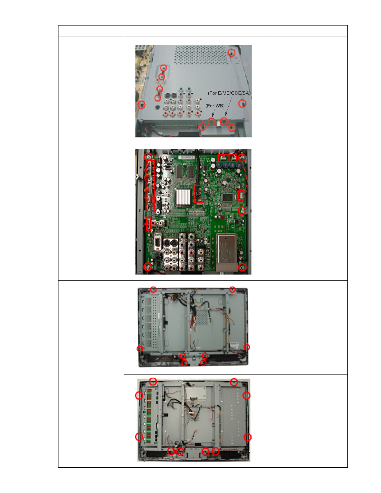
KLV-26/32/37U300A14
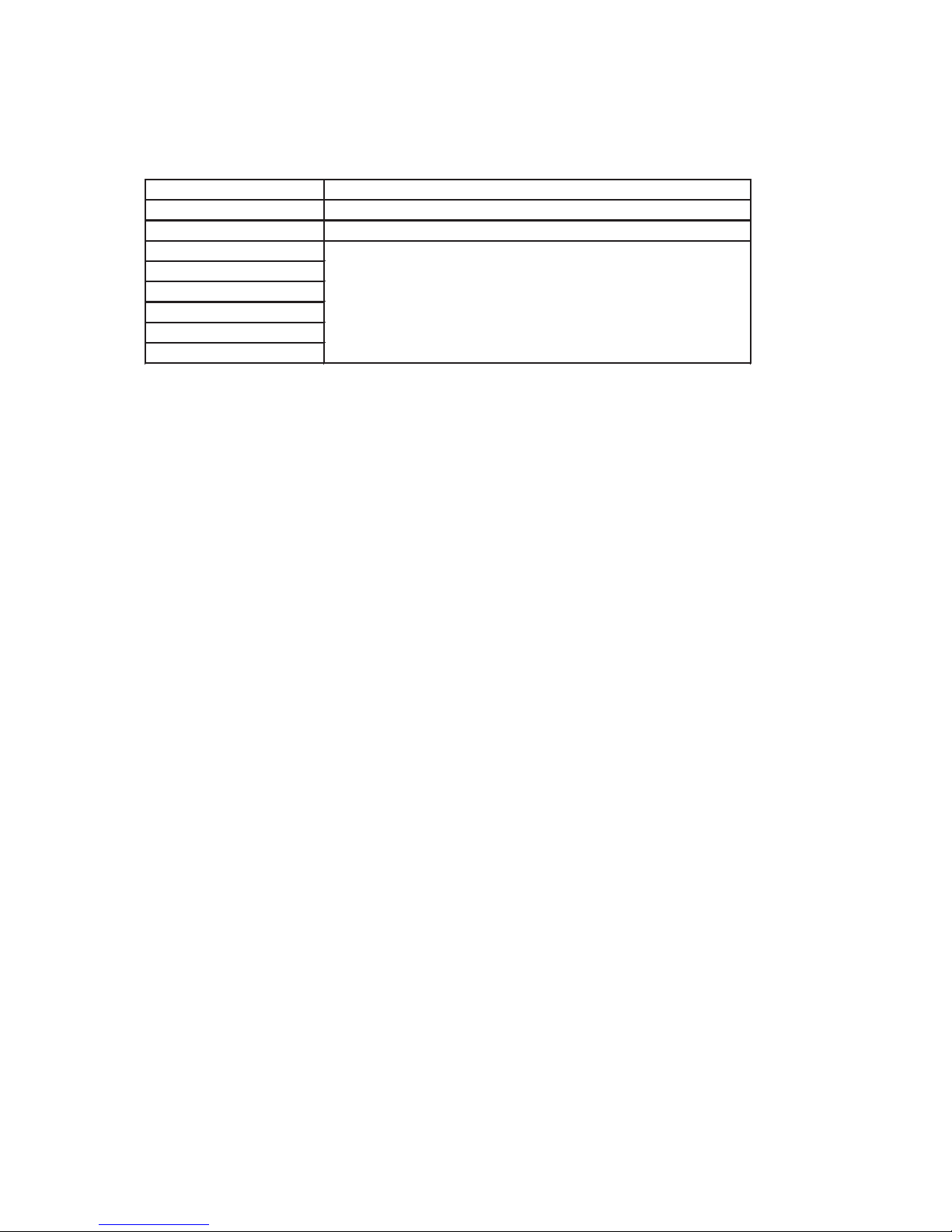
Shield Case
Removal
A Mount Removal
Bezel Removal
STEP PICTURE DESCRIPTION
Remove 10 screws to
release the Shield
Case.
Remove 5 screws and
9 connectors to release
the A Mount.
KLV-26U300A:
Remove 8 screws to
release the Bezel.
KLV-32U300A/
37U300A:
Remove 10 screws to
release the Bezel.
KLV-26/32/37U300A15
LCD Panel
Removal
STEP PICTURE DESCRIPTION
KLV-26U300A:
Remove 8 screws to
release the LCD Panel.
KLV-32U300A:
Remove 10 screws to
release the LCD Panel.
KLV-37U300A:
Remove 14 screws to
release the LCD Panel.
16 KLV-26/32/37U300A
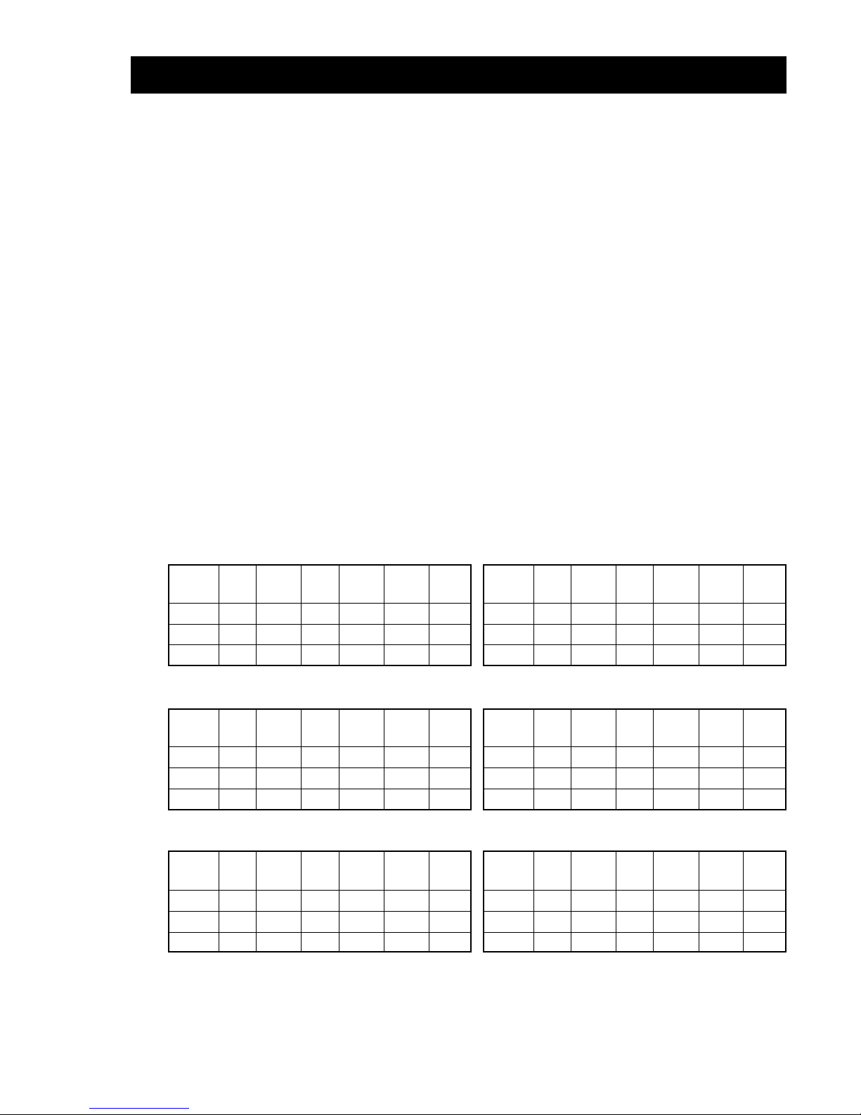
SECTION 2 : SERVICE MODE (factory mode)
To adjust various set features, use the Remote Commander to put the set into service mode to display the service menu. Input the signal
to monitor, please confirm that there is no OSD before enter the service mode.
To exit "service mode", press the MENU button
1) Press “LEFT”button
2) Press “RIGHT” button
3) Press “MUTE” button
4) Press “ENTER” button
5) Press “MUTE” button
6) Press “MENU” button
INPUT SOURCE [ VIDEO1 ]
WHITE BALANCE [ Off ]
INTERNAL PATTER [ Off ]
COLOR TEMP. [
Neutral
]
R GAIN [ 228 ]
G GAIN [ 230 ]
B GAIN [ 232 ]
R OFFSET [ 125 ]
G OFFSET [ 125 ]
B OFFSET [ 124 ]
AGING MODE [ Off ]
ADC CALIBRATION [ Off ]
FACTORY RESET [ Off ]
VGA EDID Prot. [ Off ]
HDMI EDID Prot. [ Off ]
ALL RESET [ Off ]
Recall Data [ Off ]
PANEL VERSION: AUO_32
FW: A, 1
MODEL: KLV-32U300A
Factory Menu
Menu : Save / Exit Menu
It differs according to
the model name and inducing.
17 KLV-26/32/37U300A
Before White Balance please press remote control “1” to turn on “Alignment On”, “2” is Alignment off, and AC off on Alignment will
auto off, Description of service mode (only for WB adjustment, DO NOT USE other menu)
Component 1
INPUT SOURCE
WHITE BALANCE
COLOR TEMPERTURE
R GAIN
G GAIN
B GAIN
R OFFSET
G OFFSET
B OFFSET
Default is "OFF", when you adjust white balance, change it to "ON"
Color mode change menu (COOL- NEUTRAL- WARM)
White balance adjustment resister, refer to WB adjust procedure
18 KLV-26/32/37U300A
SECTION 3 : ADJUSTMENT
3-1. Preparation
1) Allow approximately 30 minutes for the set to warm up before proceeding with the white balance adjustment.
2) Connect 3 terminal of 480i signal cable (Y/Pb/Pr) from the signal source to monitor “Component 1”
3) Enter "SERVICE MODE". The method to enter "SERVICE MODE" is described in next section.
4) Press remote control “1” to turn on “Alignment On”
5) Change "WHITE BALANCE" from "OFF" to "ON "in SERVICE MENU.
6) Select "VIDEO3" from INPUT SOURCE in SERVICE MENU
7) Set "R", "G", "B", "GAIN" and "R", "G", "B", "Offset" value as same as "3-5. AVERAGE VALUE"
3-2. Adjust White Balance of "COOL" temperature;
1) Select "COOL" from COLOR TEMPERATURE in SERVICE MENU
2) Input 70IRE Full white pattern signal into “Component 1”
3) Adjust "RGB GAIN" in SERVICE MENU if needed
4) Input 30lRE Full white pattern signal into “Component 1”
5) Adjust "RGB OFFSET" in SERVICE MENU if needed
6) Repeat adjustment of 2) to 5) so that White Balance is as same level as good monitor
3-3. Adjust White Balance of "NEUTRAL" temperature;
1) Select "NEUTRAL" from COLOR TEMPERATURE in SERVICE MENU
2) Repeat adjustment as same step of 2) to 5) till White Balance is as same level as good monitor.
3-4. Adjust White Balance of "WARM" temperature;
1) Select "WARM" from COLOR TEMPERATURE in SERVICE MENU
2) Repeat adjustment as same step of 2) to 5) till White Balance is as same level as good monitor.
3) Change "WHITE BALANCE" from "ON" to "OFF" in SERVICE MENU.
3-5. Average Value of W/B
KLV-26U300A (Except WB model):
Red Green Blue Red Green Blue
Gain Gain Gain Offset Offset Offset
Cool 232 227 253 125 122 126
Neutral 237 230 237 123 122 125
Warm 247 230 200 124 122 125
KLV-32U300A (Except WB model):
Red Green Blue Red Green Blue
Gain Gain Gain Offset Offset Offset
Cool 227 230 249 126 125 125
Neutral 229 230 232 125 125 125
Warm 242 230 204 124 125 123
KLV-37U300A (Except WB model):
Red Green Blue Red Green Blue
Gain Gain Gain Offset Offset Offset
Cool 231 230 247 126 122 122
Neutral 239 230 230 125 122 122
Warm 249 230 195 123 122 123
KLV-26U300A (WB model):
Red Green Blue Red Green Blue
Gain Gain Gain Offset Offset Offset
Cool 228 217 246 124 125 124
Neutral 240 230 240 125 125 124
Warm 250 230 203 125 125 124
KLV-32U300A (WB model):
Red Green Blue Red Green Blue
Gain Gain Gain Offset Offset Offset
Cool 234 223 255 125 125 124
Neutral 247 230 247 124 125 123
Warm 247 230 203 125 125 125
KLV-37U300A (WB model):
Red Green Blue Red Green Blue
Gain Gain Gain Offset Offset Offset
Cool 247 222 249 124 125 121
Neutral 249 230 235 125 124 122
Warm 253 227 197 125 124 123
 Loading...