

Sony KLV-37M300A Service Manual
EFB7FE
FE27E
B2DD
FD4FDFD12D7BD2F221E24EEDA2AB
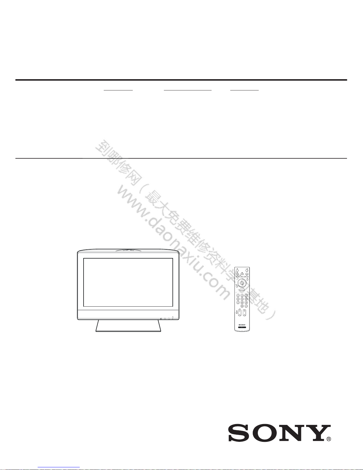
SERVICE MANUAL
LCD Colour TV
LAX U
CHASSIS
ORIGINAL MANUAL ISSUE DATE: 4/2007
REVISION DATE SUBJECT
8/2007 Correction of 3-5. Average Value of W/B and update of 6-1., 6-2. REPLACEMENT PARTS
LIST.
9-834-175-02
HISTORY INFORMATION FOR THE FOLLOWING MANUAL:
MODEL NAME REMOTE COMMANDER DESTINATION
KLV-32M300A
RM-SA012 CHINA
KLV-37M300A
RM-SA012 CHINA
00000
077
6-
1.
,
EFB7FE
FE27E
B2DD
FD4FDFD12D7BD2F221E24EEDA2AB
SERVICE MANUAL
LCD Colour TV
LAX U
CHASSIS
MODEL NAME REMOTE COMMANDER DESTINATION
KLV-32M300A
RM-SA012 CHINA
KLV-37M300A
RM-SA012 CHINA
9-834-175-02
KLV-32M300A/KLV-37M300A RM-SA012
RETURN
MENU
PROG
POWER SAVING
RETURN
ETURN
U
EFB7FE
FE27E
B2DD
FD4FDFD12D7BD2F221E24EEDA2AB
KLV-32/37M300A2
TABLE OF CONTENTS :
SPECIFICATIONS 3
WARNINGS AND CAUTIONS 5
SAFETY-RELATED COMPONENT WARNING 6
SAFETY CHECK-OUT 8
SECTION 1 : DISASSEMBLY 9
SECTION 2 : SERVICE MODE (factory mode) 15
SECTION 3 : ADJUSTMENT 17
3-1. Preparation 17
3-2. Adjust White Balance of "COOL" temperature; 17
3-3. Adjust White Balance of "NEUTRAL" temperature; 17
3-4. Adjust White Balance of "WARM" temperature; 17
3-5. Average Value of W/B 17
SECTION 4 : TIMING CHART 18
SECTION 5 : DIAGRAMS 19
5-1. BOARD Layout/WIRING Layout 19
5-1-1. KLV-32M300A 19
5-1-2. KLV-37M300A 20
5-2. Frame Diagram 21
5-3. BLOCK DIAGRAM 22
5-4. SCHEMATIC 23
5-5. PCB Layout 43
SECTION 6 : EXPLODED VIEW & REPLACEMENT PARTS LIST 49
6-1. KLV-32M300A 49
6-2. KLV-37M300A 52
A
A
Prep
aaa
aaa
tttto
ooooo
st W
h
t aaaaa
a
W
h
ttttt
t
al
a
ace o
aaaa
aaaaaaaaa
a
n
eee
e of
f W
A
/////
EFB7FE
FE27E
B2DD
FD4FDFD12D7BD2F221E24EEDA2AB
3 KLV-32/37M300A
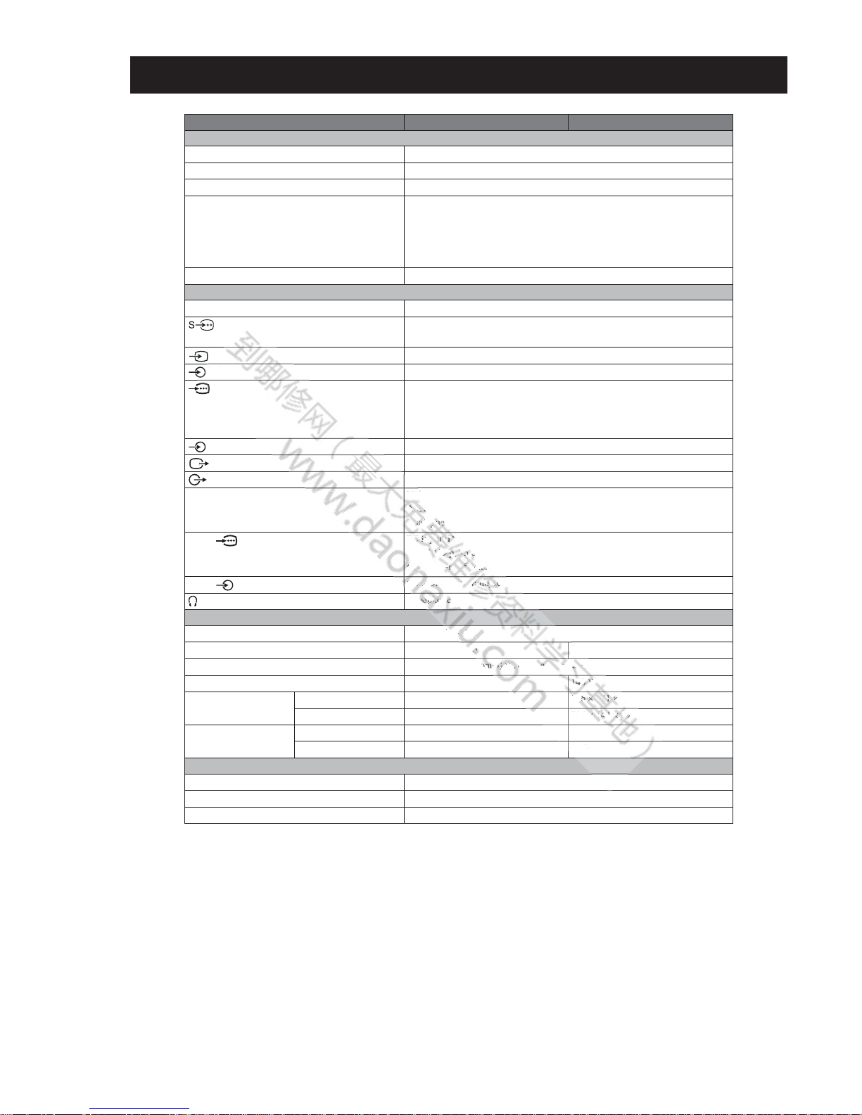
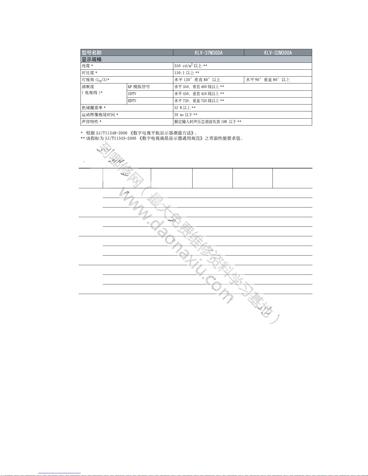
SPECIFICATIONS :
* Dimensions and mass are approximate values.
Model name KLV-37M300A KLV-32M300A
System
Panel System LCD (Liquid Crystal Display) Panel
TV System D/K, B/G, I, M
Colour System PAL, PAL60 (only Video In), NTSC4.43 (only Video In), NTSC3.58
Channel Coverage D/K: VHF: C1 to C12, R1 to R12/ UHF: C13 to C57, R21 to R60/ CATV: S01 to
S03, S1 to S41, Z1 to Z39
I: UHF: B21 to B69/ CATV: S01 to S03, S1 to S41
B/G: VHF: E2 to E12/ UHF: E21 to E69/ CATV: S01 to S03, S1 to S41
M: VHF: A2 to A13/ UHF: A14 to A79/ CATV: A-8 to A-2, A to W+4, W+6 to W+84
Sound Output 10 W + 10 W (as distortion of 7%)
Input/Output jacks
Antenna 75 ohms external terminal
1, 2 S video input (4-pin mini DIN)
Y: 1.0 Vp-p, 75 ohms unbalanced/C: 0.286 Vp-p (Burst signal), 75 ohms
1, 2 Video input (phono jacks): 1 Vp-p, 75 ohms unbalanced, sync negative
1, 2 Audio input (phono jacks): 500 mVrms, Impedance: 47 kilohms
1, 2 Component input (phone jacks)
Supported formats: 1080p, 1080i, 720p, 576p, 576i, 480p, 480i
Y: 1 Vp-p, 75 ohms, 0.3V sync negative/P
B/PB
: 0.7 Vp-p, 75 ohms/
P
R/CR
: 0.7 Vp-p, 75 ohms
1, 2 Audio input (phono jacks): 500 mVrms, Impedance: 47 kilohms
Video output (phono jack): 1 Vp-p, 75 ohms unbalanced, sync negative
Audio output (phono jacks): 500 mVrms (100% modulation)
HDMI IN Video: 1080p, 1080i, 720p, 576p, 576i, 480p, 480i
Audio: Two channel linear PCM 32, 44.1 and 48 kHz, 16, 20 and 24 bits
Analogue audio input (phono jacks): 500 mVrms, Impedance: 47 kilohms
PC IN (RGB) PC Input (D-sub 15-pin)
G: 0.7 Vp-p, 75 ohms, non Sync on Green/B: 0.7 Vp-p, 75 ohms/
R: 0.7 Vp-p, 75 ohms/HD: 1-5 Vp-p/VD: 1-5 Vp-p
PC IN PC audio input (minijack): 500 mVrms, Impedance: 47 kilohms
Headphones jack
Power and others
Power Requirements 220 V AC, 50 Hz
Viewing Screen Size (diagonal) 94 cm (37 inches) 80 cm (32 inches)
Display Resolution 1,366 pixels (horizontal) × 768 lines (vertical)
Power Consumption 155 W 140 W
Dimensions
(w × h × d)*
with stand (mm) 918 × 656 × 264 796 × 591 × 214
without stand (mm) 918 × 609 × 108 796 × 544 × 99
Mass* with stand (kg) 21.0 16.5
without stand (kg) 18.0 14.0
Product usage condition
Environment Temperature 5°C - 35°C
Humidity 20% - 80%
Air Pressure 86 kPa - 106 kPa
2
2
2
Vi
io:ii
T
log
log
log
log
log
g
ue
ue
au
PCPCPCPCPCPCPC
PC
InInInInIn
In
putput
put
putpput(DD(D(D
D
b
0.7
-p,
-p,
-p,
-p,
-
75
75
75
75
ohoo
m
0.700
Vp
-p,
-p-p75757575
ms/mm
H
P
C aaudi
udi
udi
udi
udi
o i
o
t (
t (
t (
t
minmin
ija
ijaija
ija
ija
ijaijck)cck)
)
dph
dph
dph
one
one
one
s j
ack
50
HzHzHzHz
)
)
0
on
tal
tal
tal
tal
)
)
)
)
)
li
nes
(v
(v
e
ert
ereica
1414141414
0 W
W
796
796
44
16.
14
.0
EFB7FE
FE27E
B2DD
FD4FDFD12D7BD2F221E24EEDA2AB
4 KLV-32/37M300A
Design and specifications are subject to change without notice.
PC Input Signal Reference Chart
• This TV’s PC input does not support Sync on Green or Composite Sync.
• This TV’s PC input does not support interlaced signals.
• For the best picture quality, it is recommended to use the signals (boldfaced) in the above chart with a 60 Hz
vertical frequency from a personal computer. In plug and play, signals with a 60 Hz vertical frequency will be
selected automatically.
Signals
Horizontal
(Pixel)
Vertical (Line)
Horizontal
frequency (kHz)
Vertical
frequency (Hz)
Standard
VGA 640 480 31.5 60 VGA
640 480 37.5 75 VESA
720 400 31.5 70
VGA-T
SVGA 800 600 37.9 60 VESA Guidelines
800 600 46.9 75 VESA
XGA 1024 768 48.4 60 VESA Guidelines
1024 768 56.5 70 VESA
1024 768 60 75 VESA
WXGA 1280 768 47.4 60 VESA
1280 768 47.8 60 VESA
1360 768 47.7 60 VESA
nc
c
ce
d) in the
abchchchch
cchchart
w
h
a 60 Hz ve
rticicicalal
f
re
qu
e
76
7676
6
444444888
8
4
44444
4
666
6
0
0
58585
555
5
5
768888
84
8
8
0
666
66666
000000
00
444
0000
0
00000
rizo
ntal
ixel
)
andnd
nd
pepepe
p
cicifi
ca
Input Sig
fefefefererere
e
EFB7FE
FE27E
B2DD
FD4FDFD12D7BD2F221E24EEDA2AB
5 KLV-32/37M300A
WARNINGS AND CAUTIONS
CAUTION
These servicing instructions are for use by qualified service personnel only. To reduce the risk of electric shock, do not perform any
servicing other than that contained in the operating instructions unless you are qualified to do so.
WARNING!!
An isolation transformer should be used during any service to avoid possible shock hazard, because of live chassis.The chassis of
this receiver is directly connected to the ac power line.
!
SAFETY-RELATED COMPONENT WARNING!!
Replace all components with Sony parts whose part numbers appear as shown in this manual or in supplements
published by Sony.
onen
tsww
ititithh
nynnpony.
EFB7FE
FE27E
B2DD
FD4FDFD12D7BD2F221E24EEDA2AB
6 KLV-32/37M300A
SAFETY-RELATED COMPONENT WARNING
It is essential that all critical parts be replaced only with the part number specified in the electrical parts list to prevent electric shock,
fire, or other hazard.
NOTE: Do not modify the original design without obtaining written permission from the manufacturer or you will void the original parts and
labor guarantee.
USE CAUTION WHEN HANDLING THE LCD PANEL
When repairing the LCD panel, be sure you are grounded by using a wrist band.
To avoid damaging the LCD panel:
do not press on the panel or frame edge to avoid the risk of electric shock.
do not scratch or press on the panel with any sharp objects.
do not leave the module in high temperatures or in areas of high humidity for an extended period of time.
do not expose the LCD panel to direct sunlight.
avoid contact with water. It may cause a short circuit within the module.
disconnect the AC power when replacing the backlight (CCFL) or inverter circuit.
(High voltage occurs at the inverter circuit at 650Vrms.)
always clean the LCD panel with a soft cloth material.
use care when handling the wires or connectors of the inverter circuit. Damaging the wires may cause a short.
protect the panel from ESD to avoid damaging the electronic circuit (C-MOS).
LEAKAGE CURRENT HOT CHECK CIRCUIT
AC Volt-meter
To Instruments
exposed
METALLIC PARTS
1.5 Kohm/10W
Good Earth Ground
Such as WATER PIPE,
CONDUIT etc.
tcho
vevettt
t
t
he
h
h
txposososososososthth
th
cont
ac
t wiwi
thththththwwwwe
on
nect t
heAAAwewwe
we
w
w
we
w
vo
ltage oc
cu
t
t t t t
t tt ththee
e
an the L
CDwwwh
n handling
thehehehehe
wires
o
l from ESD tavoi
d
E
AKAKAKAK
AGAGU
Vololololot-t-t-t
t
dsDUDUDUIDUT

EFB7FE
FE27E
B2DD
FD4FDFD12D7BD2F221E24EEDA2AB
7 KLV-32/37M300A
The circuit boards used in these models have been processed using
Lead Free Solder.
The servicing of these boards requires special precautions to be taken
as outlined below.
It is strongly recommended to use Lead Free Solder material in order to guarantee optimal quality of new solder joints.
Lead Free Solder is available under the following part numbers:
Due to the higher melting point of Lead Free Solder the soldering iron tip temperature needs to be set to 370 degrees centigrade.
This requires soldering equipment capable of accurate temperature control coupled with a good heat recovery characteristics.
For more information on the use of Lead Free Solder, please refer to http://www.sony-training.com
eeeeee
Solthe s
e s
e ssold
le e e
of
of
of
of
of
of
acc
ura
te
tem
at
Sol
Sol
Sol
leaato
tth
EFB7FE
FE27E
B2DD
FD4FDFD12D7BD2F221E24EEDA2AB
8 KLV-32/37M300A
SAFETY CHECK-OUT
After correcting the original service problem, perform the
following safety checks before releasing the set to the customer:
1. Check the area of your repair for unsoldered or poorly soldered connections. Check the entire board surface for solder
splashes and bridges.
2. Check the interboard wiring to ensure that no wires are
“pinched” or touching high-wattage resistors.
3. Check that all control knobs, shields, covers, ground straps,
and mounting hardware have been replaced. Be absolutely certain that you have replaced all the insulators.
4. Look for unauthorized replacement parts, particularly transistors, that were installed during a previous repair. Point them
out to the customer and recommend their replacement.
5. Look for parts which, though functioning, show obvious signs
of deterioration. Point them out to the customer and recommend their replacement.
6. Check the line cords for cracks and abrasion. Recommend the
replacement of any such line cord to the customer.
7. Check the antenna terminals, metal trim, “metallized” knobs,
screws, and all other exposed metal parts for AC leakage. Check
leakage as described below.
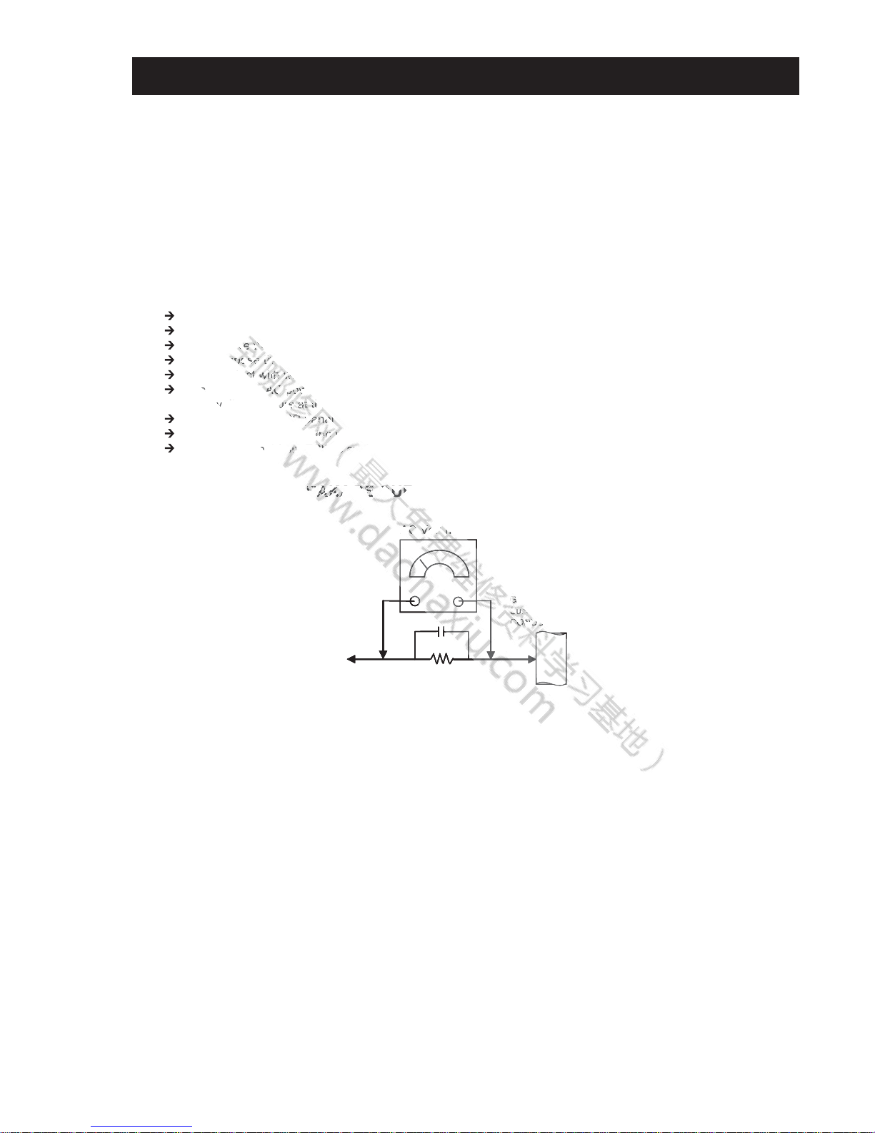
LeakageTest
The AC leakage from any exposed metal part to earth ground and
from all exposed metal parts to any exposed metal part having a
return to chassis, must not exceed 0.5 mA (500 microamperes).
Leakage current can be measured by any one of three methods.
1. A commercial leakage tester, such as the Simpson 229 or RCA
WT-540A. Follow the manufacturers’ instructions to use these
instructions.
2. A battery-operated AC milliampmeter. The Data Precision 245
digital multimeter is suitable for this job.
3. Measuring the voltage drop across a resistor by means of a
VOM or battery-operated AC voltmeter. The “limit” indication is 0.75V, so analog meters must have an accurate low voltage scale.
The Simpson’s 250 and Sanwa SH-63TRD are examples of
passive VOMs that are suitable. Nearly all battery-operated
digital multimeters that have a 2 VAC range are suitable (see
Figure A).
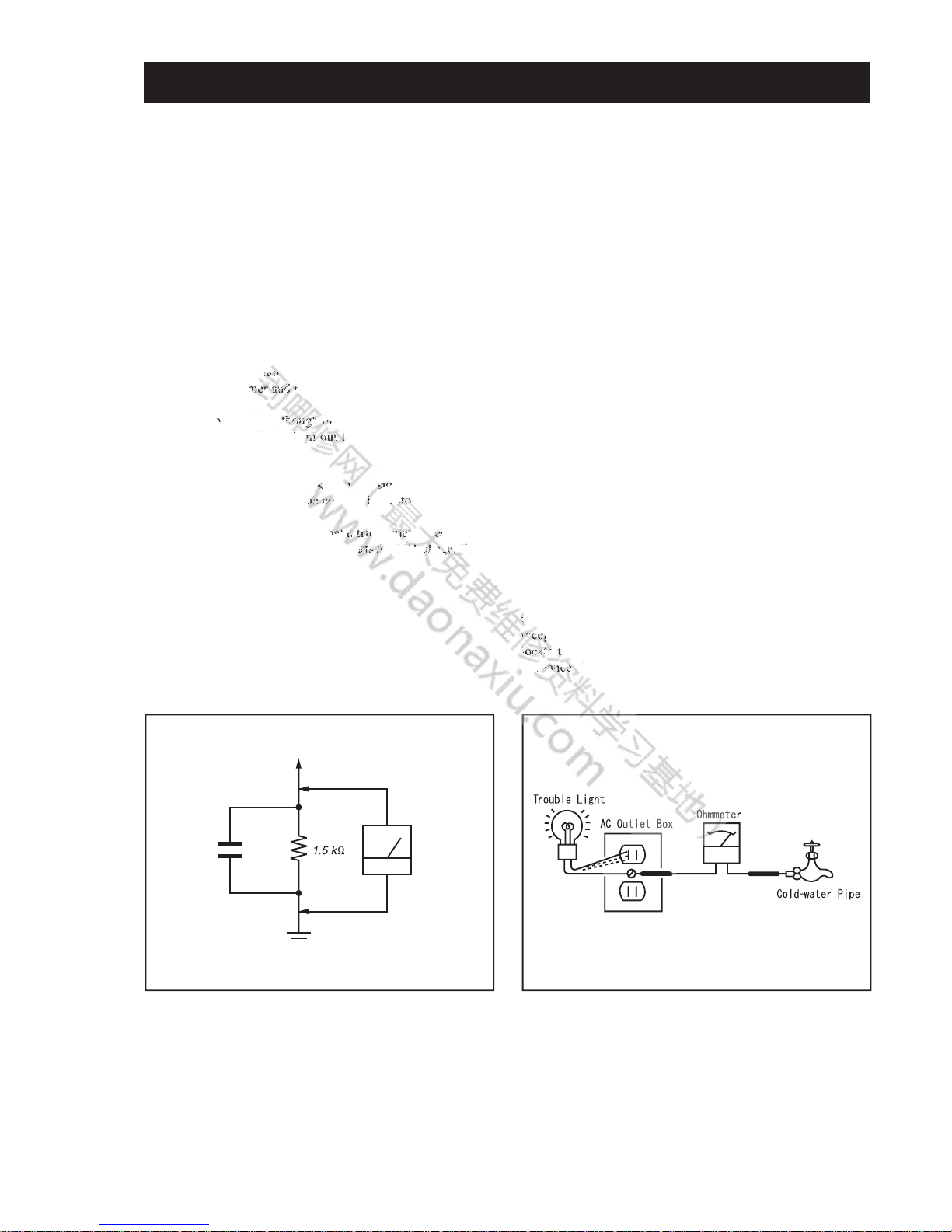
How to Find a Good Earth Ground
A cold-water pipe is a guaranteed earth ground; the cover-plate
retaining screw on most AC outlet boxes is also at earth ground. If
the retaining screw is to be used as your earth ground, verify that
it is at ground by measuring the resistance between it and a coldwater pipe with an ohmmeter. The reading should be zero ohms.
If a cold-water pipe is not accessible, connect a 60- to 100-watt
trouble- light (not a neon lamp) between the hot side of the
receptacle and the retaining screw. Try both slots, if necessary, to
locate the hot side on the line; the lamp should light at normal
brilliance if the screw is at ground potential (see Figure B).
To Exposed Metal
Parts on Set
0.15
μ
F
Earth Ground
AC
Voltmeter
(0.75V)
Figure A. Usingan AC voltmeter to check AC leakage.
Figure B. Checking for earth ground.
d
stalalalalalleled
d
mer ananand d d d rrrreco
ar
ts which,
ououou
ghghghghghgh
f
ffffun
u
u
u
ct
on
. Point
themooooutututututtto
th
ce
ment.
or
cracks
anabrasisision. R
lineeccccccoroororod
dtotheh custotototmem
r
alalaltt
ttri
riririririri
mm,mmmm
metalliziz
k
pa
rt
rtrtrtrts s s fo
fofofofor ACeaka
k..ChCCC
e
b
cece
ptpp
ac
cacaca
tetetetete
he
illicececef
th
EFB7FE
FE27E
B2DD
FD4FDFD12D7BD2F221E24EEDA2AB
KLV-32/37M300A9
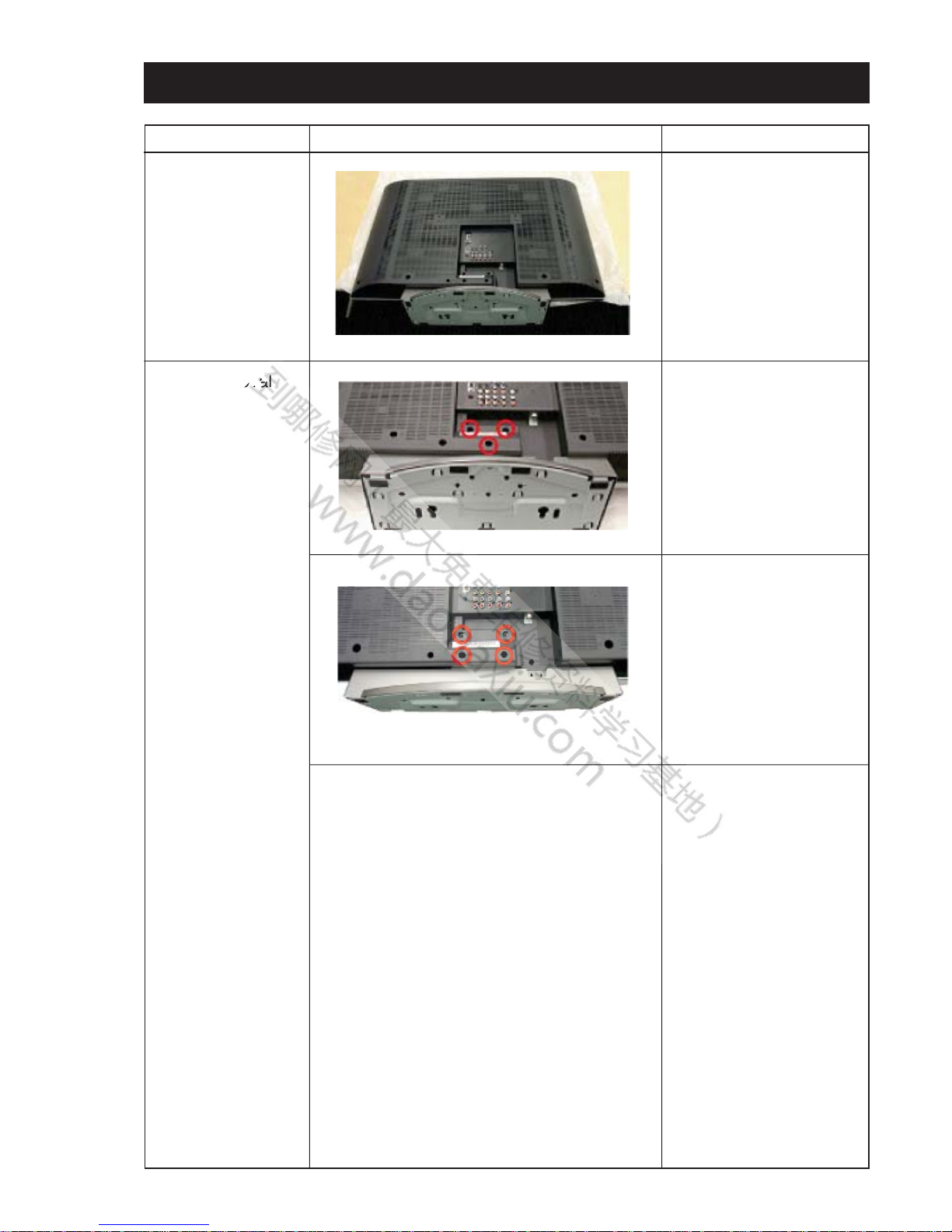
SECTION 1 : DISASSEMBLY
STEP PICTURE DESCRIPTION
Gently place the TV set
face down on the table.
KLV-32M300A:
Remove 3 screws to
release the Tabletop
Stand from the unit.
KLV-37M300A:
Remove 4 screws to
release the Tabletop
Stand from the unit.
Service Position
Stand Removal
vavava
va
EFB7FE
FE27E
B2DD
FD4FDFD12D7BD2F221E24EEDA2AB
KLV-32/37M300A10
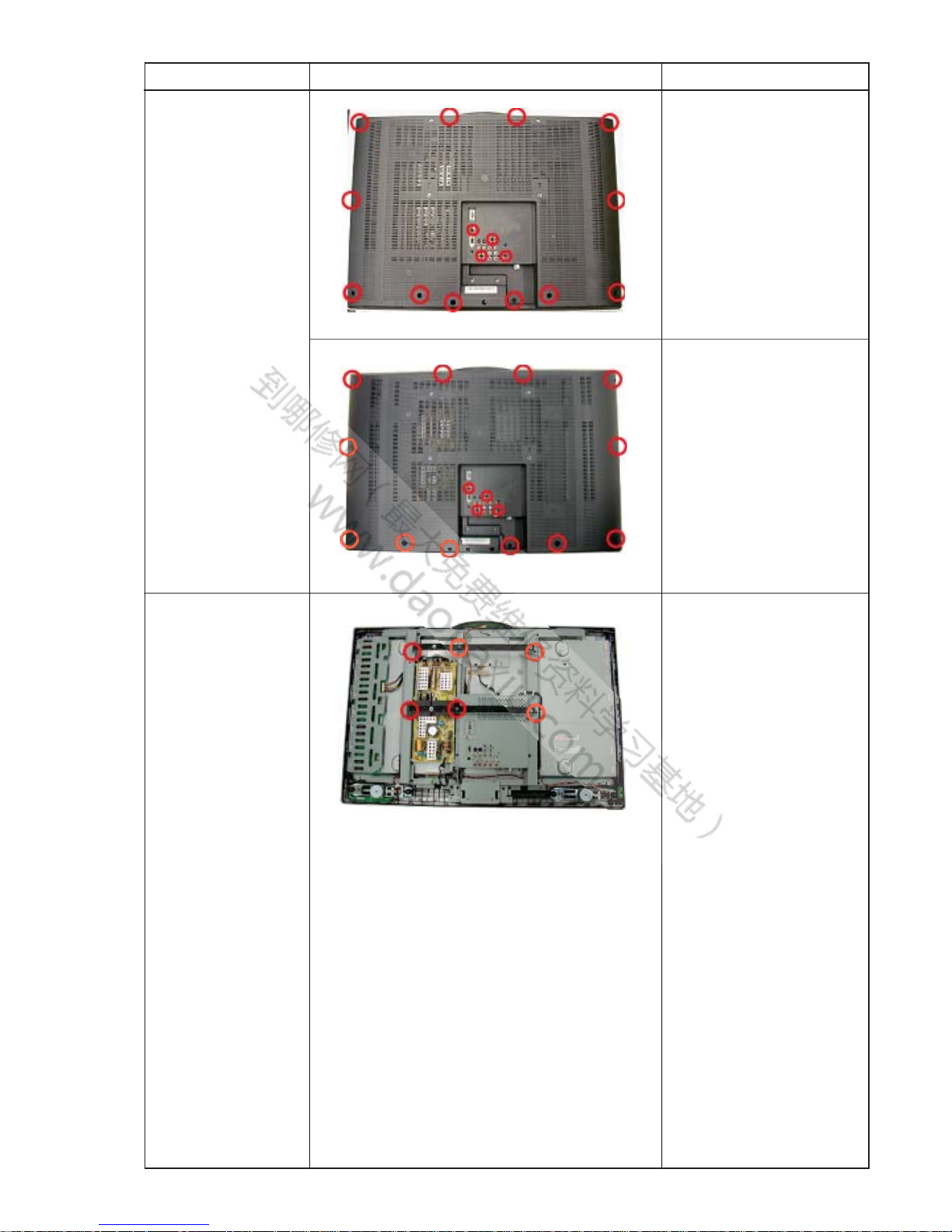
Rear Cover
Removal
Wall Mount
Bracket
Removal
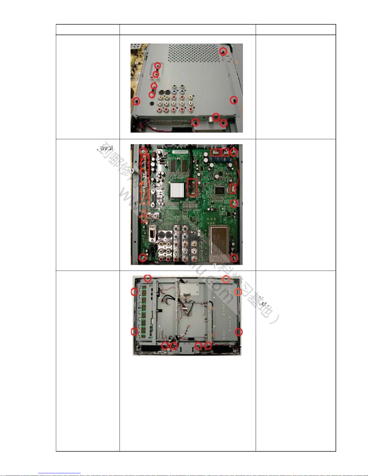
STEP PICTURE DESCRIPTION
KLV-32M300A:
Remove 16 screws to
release the rear cover.
KLV-37M300A:
Remove 16 screws to
release the rear cover.
Remove 6 screws to
release the Wall Mount
Bracket.
EFB7FE
FE27E
B2DD
FD4FDFD12D7BD2F221E24EEDA2AB
KLV-32/37M300A11
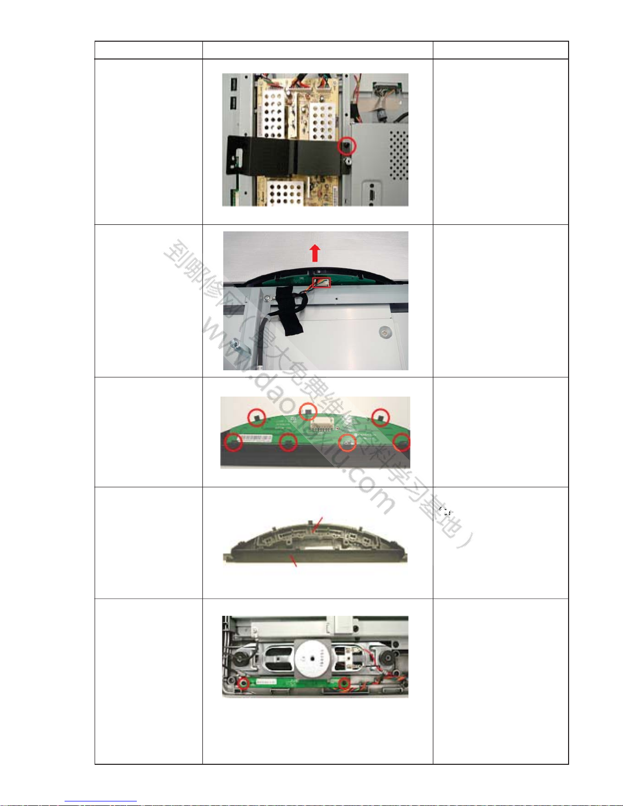
Cover Sheet
Removal
Botton ASSY
Removal
H1 Mount
Removal
Key Cover and
Multi Botton
Removal
H2 Mount
Removal
STEP PICTURE DESCRIPTION
Remove 1 screw to
release the Cover
Sheet.
Remove function cable
from function board
connector.
Bend key cover hooks
to release function
board.
Dismantle function key
form function key cover.
Remove 2 screws and
1 connector to release
the H2 Mount.
Multi Button
Function Key Cover
s
EFB7FE
FE27E
B2DD
FD4FDFD12D7BD2F221E24EEDA2AB
KLV-32/37M300A12
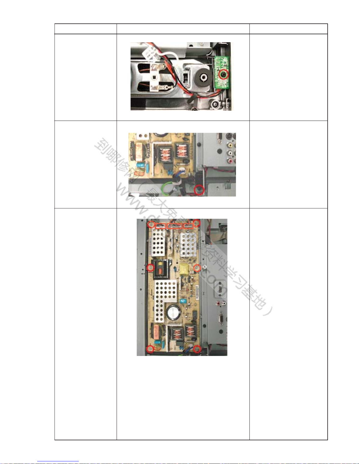
H3 Mount
Removal
AC Inlet Removal
G Mount Removal
STEP PICTURE DESCRIPTION
Remove 1 screw and
1 connector to release
the H3 Mount.
Remove 1 screw and
1 connector to release
the AC Inlet.
Remove 6 screws and
3 connectors to release
the G Mount.
EFB7FE
FE27E
B2DD
FD4FDFD12D7BD2F221E24EEDA2AB
KLV-32/37M300A13
Shield Case
Removal
A Mount Removal
Bezel Removal
STEP PICTURE DESCRIPTION
Remove 10 screws to
release the Shield
Case.
Remove 5 screws and
9 connectors to release
the A Mount.
KLV-32M300A/
37M300A:
Remove 10 screws to
release the Bezel.
movavavavava
EFB7FE
FE27E
B2DD
FD4FDFD12D7BD2F221E24EEDA2AB
KLV-32/37M300A14
LCD Panel
Removal
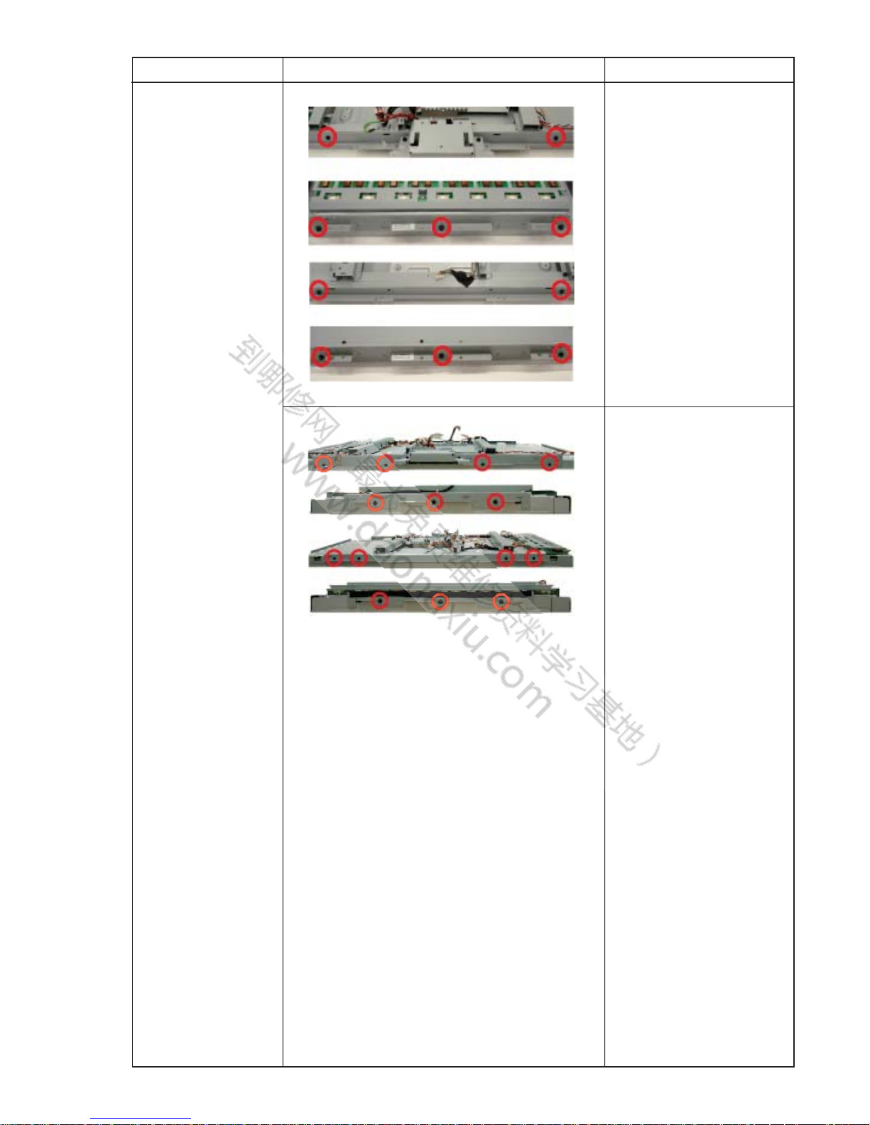
STEP PICTURE DESCRIPTION
KLV-32M300A:
Remove 10 screws to
release the LCD Panel.
KLV-37M300A:
Remove 14 screws to
release the LCD Panel.
EFB7FE
FE27E
B2DD
FD4FDFD12D7BD2F221E24EEDA2AB
15 KLV-32/37M300A
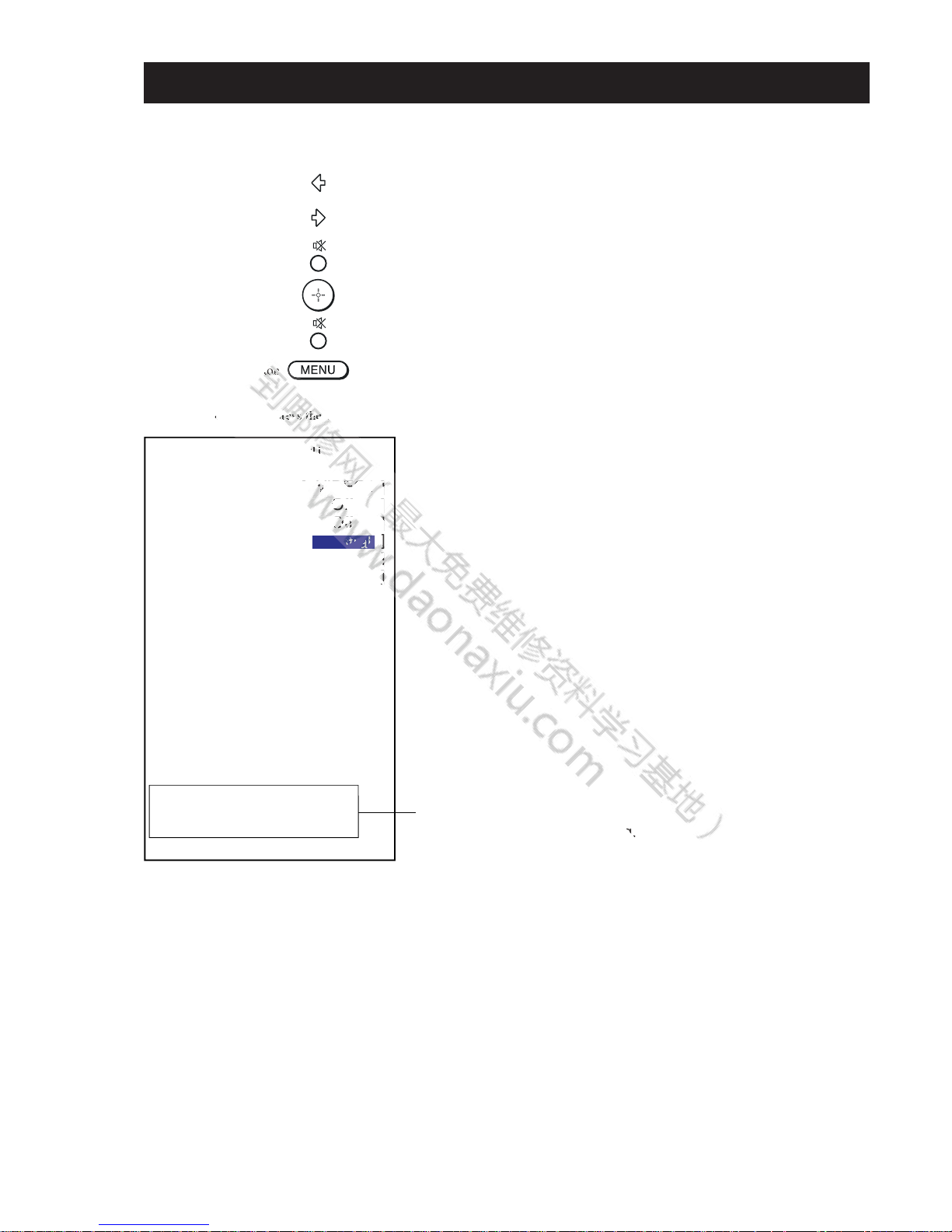
SECTION 2 : SERVICE MODE (factory mode)
To adjust various set features, use the Remote Commander to put the set into service mode to display the service menu. Input the signal
to monitor, please confirm that there is no OSD before enter the service mode.
To exit "service mode", press the MENU button
1) Press “LEFT”button
2) Press “RIGHT” button
3) Press “MUTE” button
4) Press “ENTER” button
5) Press “MUTE” button
6) Press “MENU” button
INPUT SOURCE [ VIDEO1 ]
WHITE BALANCE [ Off ]
INTERNAL PATTER [ Off ]
COLOR TEMP. [
Neutral
]
R GAIN [ 229 ]
G GAIN [ 230 ]
B GAIN [ 235 ]
R OFFSET [ 124 ]
G OFFSET [ 125 ]
B OFFSET [ 123 ]
AGING MODE [ Off ]
ADC CALIBRATION [ Off ]
FACTORY RESET [ Off ]
VGA EDID Prot. [ Off ]
HDMI EDID Prot. [ Off ]
ALL RESET [ Off ]
Recall Data [ Off ]
PANEL VERSION: AUO_32
FW: A, 1
MODEL: KLV-32M300A
Factory Menu
Menu : Save / Exit Menu
It differs according to
the model name and inducing.
ce
mode",
pr
s s s
ththth
thththe ME
M
tonn
n
n
VVVVVVV
]
OfOOfOfOf
f]
f]
]]OOO
OOO
O
O
ffffffffff
ff
or
y Me
 Loading...