

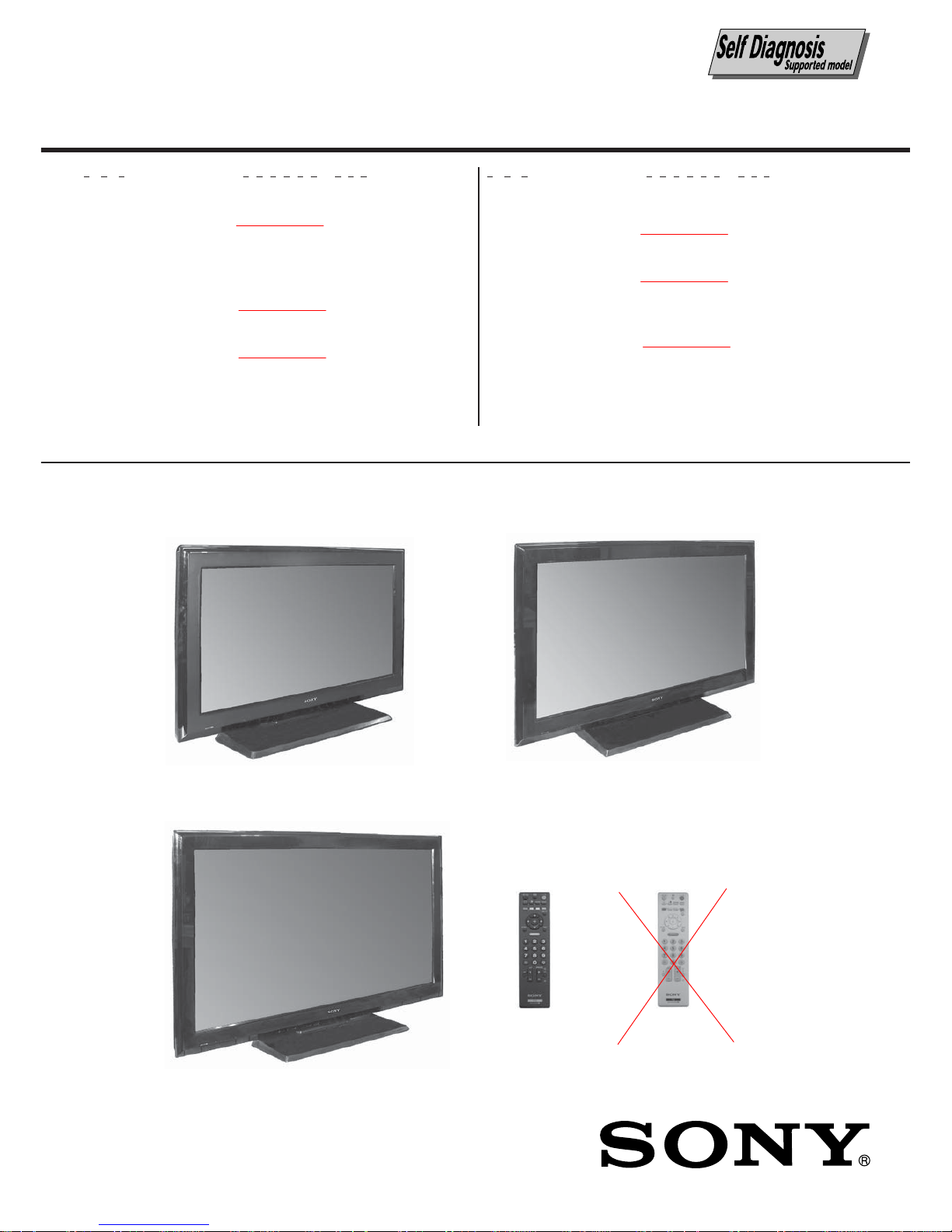
Sony KLV-32S530A, KLV-32S550A, KLV-32S550T, KLV-32S550L, KLV-37S550A Service Manual
...
CHASSIS
LCD COLOR TV
SERVICE MANUAL
MODEL COMMANDER DEST.
KLV-26S550A
RM-GA016 & GE, India, ME,
RM-GA016W Philippines, Russia,
South Africa, Thailand
KLV-32S530A
RM-GA016 & ME, Thailand
RM-GA016W
KLV-32S550A
RM-GA016 & GE, India, Iran, ME,
RM-GA016W New Zealand,
Philippines, Russia,
South Africa, Thailand
Tunisia
RM-GA016
EX2T
KLV-26S550A KLV-32S550A
KLV-37S550A
MODEL COMMANDER DEST.
KLV-32S550A/L
RM-GA016 & GE, ME, Philippines,
(Blue) RM-GA016W Russia, South Africa
KLV-32S550A/T
RM-GA016 & GE, ME, Philippines,
(Brown) RM-GA016W Russia, South Africa
KLV-37S550A
RM-GA016 & GE, India, Iran, ME,
RM-GA016W Thailand, Tunisia
Philippines, Russia,
RM-GA016W
REVISION HISTORY
NO. SUFFIX DATE SUPP / CORR DESCRIPTION
1 -01 2009/01 _ _ 1st Issue
2 -02 2009/03 Supp-1 Part Information Change: Addition of:
i) Removal and Installation of Rear Cover and
Switch Unit removal. (
Page 45)
ii) Triage Chart (
Page 46)
iii) Trouble Shooting (Page 47~50)
3 -03 2009/05 Supp-2 Part Information Change: Addition of:
i) Stand Assy (
Page 52)
ii) Fall Lock Belt Bag Assy (Page 53)
4 -04 2009/05 Corr-1 Remote Commander type deletion from:
i) Cover Page
ii) All headings
iii) Electrical Part List (
Page 41~43)
iv) Supplement-1 Cover Page
v) Supplement-2 Cover Page
5 -05 2009/07 Supp-3 Part Information Changed - LCD Panel Part Number
(Page 54)
6 -06 2009/07 Supp-4 New Model Addition (Page 57)
EX2T
CHASSIS
MODEL
KLV-26S550A
KLV-32S530A
KLV-32S550A
KLV-32S550A/L
KLV-32S550A/T
KLV-37S550A
PART NO.: 9-888-103-06

– 2 –
KLV-32S530A, 26, 32, 37 S550A
RM-GA016
RM-GA016W
TABLE OF CONTENTS
1. SAFETY NOTES
1-1. Caution Handling of LCD Panel .....................................3
1-2. Safety Check Out............................................................. 3
1-3. Leakage Test ....................................................................3
1-4. WARNING ! .................................................................... 3
1-5. Lead Free Information..................................................... 4
2. SELF DIAGNOSTIC FUNCTION
2-1. Overview of Control Buttons .......................................... 5
2-2. LED Display Specification.............................................. 5
2-3. LED Display Control....................................................... 5
2-4. LED Pattern ..................................................................... 5
2-5. Viewing the Service Diagnosis Display.......................... 5
2-6. Standby LED Error Display ............................................ 6
2-7. Triage Chart .....................................................................6
3. TROUBLE SHOOTING.................................................. 7
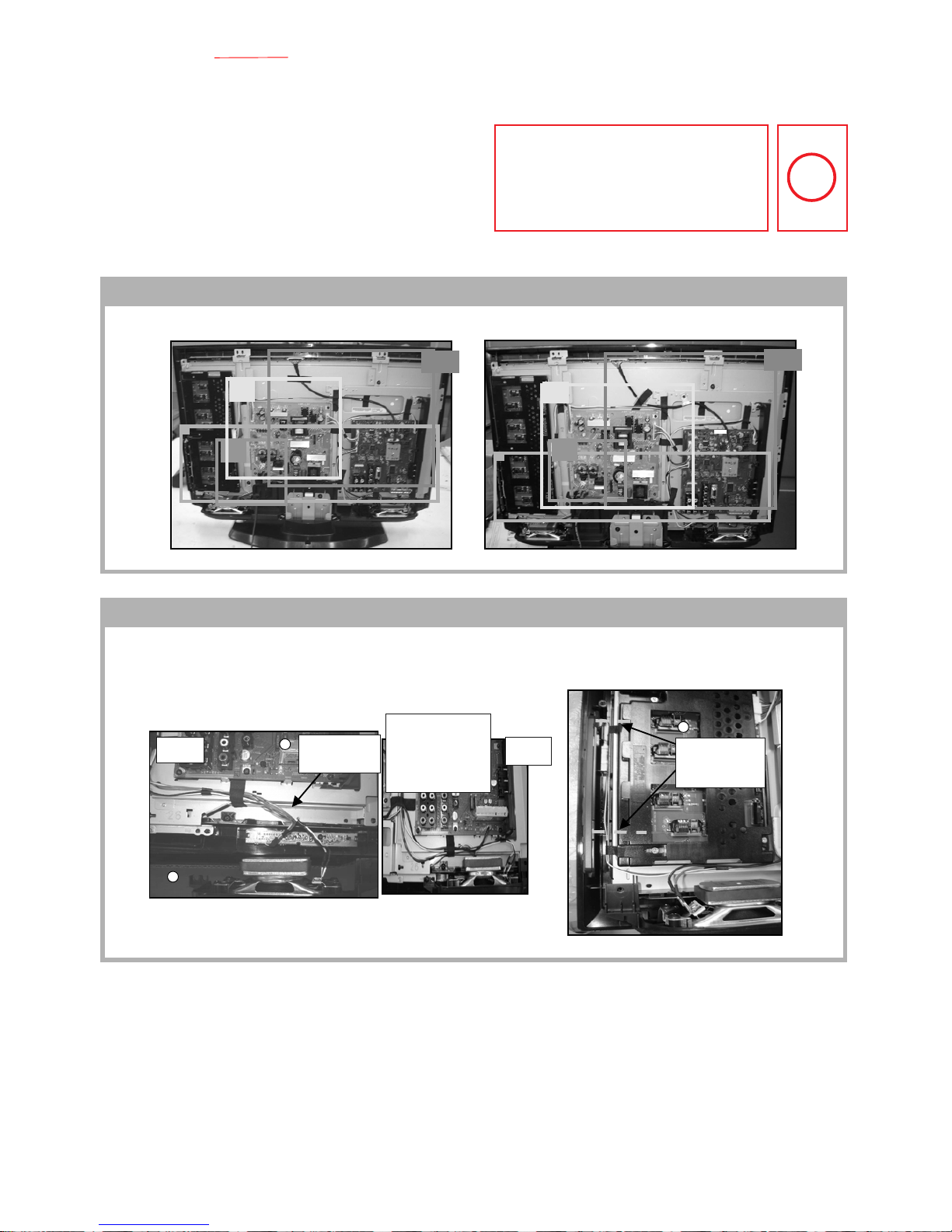
4. DISASSEMBLY
4-1. KLV-26S550A ................................................................. 8
4-2. KLV-32S530A, 32S550A, 32S550A/L, 32S550A/T ...... 9
4-3. KLV-37S550A ............................................................... 10
5. WIRE DRESSING
5-1. KLV-26S550A ............................................................... 12
5-2. KLV-32S530A, 32S550A, 32S550A/L, 32S550A/T .... 15
5-3. KLV-37S550A ............................................................... 18
6. SERVICE ADJUSTMENTS
6-1. Accessing Diagnostic Menu.......................................... 21
6-2. Viewing the Service Mode Display ..............................21
6-3. Control Keys Via Remote Commander......................... 21
6-4. Adjustment Method .......................................................21
6-5. Table 1............................................................................ 23
6-6. Board & Panel Replacement ......................................... 23
Section Title P age
Section Title Pa g e
7. DIAGRAMS
7-1. Block Diagram............................................................... 24
7-1-1. BT2 Board ......................................................... 24
7-1-2. GT3 Board (Except 37S550A).......................... 27
7-1-3. HT1 Board ......................................................... 29
7-2. Connector Diagram ....................................................... 30
7-2-1. KLV-26S550A ................................................... 30
7-2-2. KLV-32S530A, 32S550A, 32S550A/L,
32S550A/T......................................................... 31
7-2-3. KLV-37S550A ................................................... 31
7-3. Circuit Board Location..................................................32
7-3-1. KLV-26S550A ................................................... 32
7-3-2. KLV-32S530A, 32S550A, 32S550A/L,
32S550A/T......................................................... 32
7-3-3. KLV-37S550A ................................................... 33
7-4. Schematic Diagram Information ...................................34
7-5. Printed Wiring Boards ...................................................34
7-6. Semiconductor ............................................................... 34
8. EXPLODED VIEWS
8-1. KLV-26S550A ............................................................... 35
8-2. KLV-32S530A, 32S550A, 32S550A/L, 32S550A/T .... 37
8-3. KLV-37S550A ............................................................... 39
9. ELECTRICAL PARTS LIST
9-1. KLV-26S550A ............................................................... 41
9-2. KLV-32S530A, 32S550A, 32S550A/L, 32S550A/T .... 41
9-3. KLV-37S550A ............................................................... 42
OPERATING INSTRUCTIONS
– 3 –
KLV-32S530A, 26, 32, 37 S550A
RM-GA016
RM-GA016W
1-1. Caution Handling of LCD Panel
When installing the LCD Panel, make sure you are grounded
with a wrist band.
When installing the LCD Panel on the wall, the panel must be
secured using the 4 mounting holes on the rear cover.
1) Do not press the panel or frame edge to avoid the risk of
electric shock.
2) Do not scratch or press on the panel with any sharp
objects.
3) Do not leave the module in high temperature or in areas of
high humidity for an extended period of time.
4) Do not expose the LCD panel to direct sunlight.
5) Avoid contact with water. It may cause short circuit within
the module.
6) Disconnect the AC adapter when replacing the backlight
(CCFL) or inverter circuit. (High voltage occurs at the inverter
circuit at 650Vrms)
7) Always clean the LCD panel with a soft cloth material.
8) Use care when handling the wires or connectors of the
inverter circuit. Damaging the wires may cause a short circuit.
9) Protect the panel from ESD to avoid damaging the electronic circuit (C-MOS).
1-2. Safety Check-Out
After correcting the original service problem, perform the
following safety checks before releasing the set to the
customer:-
1) Check the area of your repair for unsoldered or poorly
soldered connections. Check the entire board surface for
solder splashes and bridges.
2) Check the interboard wiring to ensure that no wires are
"pinched" or contact high-wattage resistors.
3)Check all control knobs, shields, covers, ground straps and
mounting hardware have been replaced. Be absolutely certain
you have replaced all the insulators.
4) Look for unauthorized replacement parts, particularly
transistors that were installed during a previous repair. Point
them out to the customer and recommend their replacement.
5) Look for parts which, though functioning show obvious
signs of deterioration. Point them out to the customer and
recommend their replacement.
6) Check the line cords for cracks and abrasion.
Recommend the replacement of any such line cord to the
customer.
7) Check the antenna terminals, metal trim, "metallized"
knobs, screws and all other exposed metal parts for AC
leakage. Check leakage test as described next.
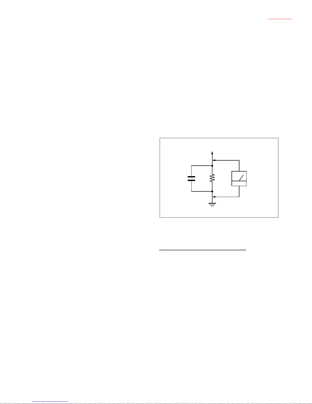
1-3. Leakage Test
The AC leakage from any exposed metal part to earth
ground and from all exposed metal parts to any exposed
metal part having a return to chassis must not exceed 0.5mA
(500 microamperes). Leakage current can be measured by
any one of the three methods:-
1. A commercial leakage tester such as the SIMPSON 229 or
RCA WT-540A. Follow the manufacturers instructions to use
those instructions.
2. A battery-operated AC milliampmeter. The DATA
PRECISION 245 digital multimeter is suitable for this job.
3. Measuring the voltage drop across a resistor by means of
a VOM or battery operated AC voltmeter. The 'limit' indication
is 0.75V so analog meters must have an accurate low voltage
scale. The SIMPSON'S 250 and SANWA SH-63TRD are
examples of passive VOMs that are suitable. Nearly all battery
operated digital multimeters that have a 2 VAC range are
suitable. (see Figure 1.)
1.5 k
1
0.15 μF
AC
Voltmeter
(0.75 V)
To Exposed Metal
Parts on Set
Earth Ground
SECTION 1
SAFETY NOTES
Figure 1. AC voltmeter to check AC leakage
1-4. W ARNING !
SAFETY-RELATED COMPONENT WARNING!
COMPONENTS IDENTIFIED BY SHADING AND MARK
!
ON THE EXPLODED VIEWS ARE CRITICAL FOR SAFE
OPERATION. REPLACE THESE COMPONENTS WITH
SONY PARTS WHOSE PART NUMBERS APPEAR AS
SHOWN IN THIS MANUAL OR IN SUPPLEMENTS
PUBLISHED BY SONY. CIRCUIT ADJUSTMENTS THAT ARE
CRITICAL FOR SAFE OPERATION ARE IDENTIFIED IN
THIS MANUAL. FOLLOW THESE PROCEDURES
WHENEVER CRITICAL COMPONENTS ARE REPLACED
OR IMPROPER OPERATION IS SUSPECTED.
– 4 –
KLV-32S530A, 26, 32, 37 S550A
RM-GA016
RM-GA016W
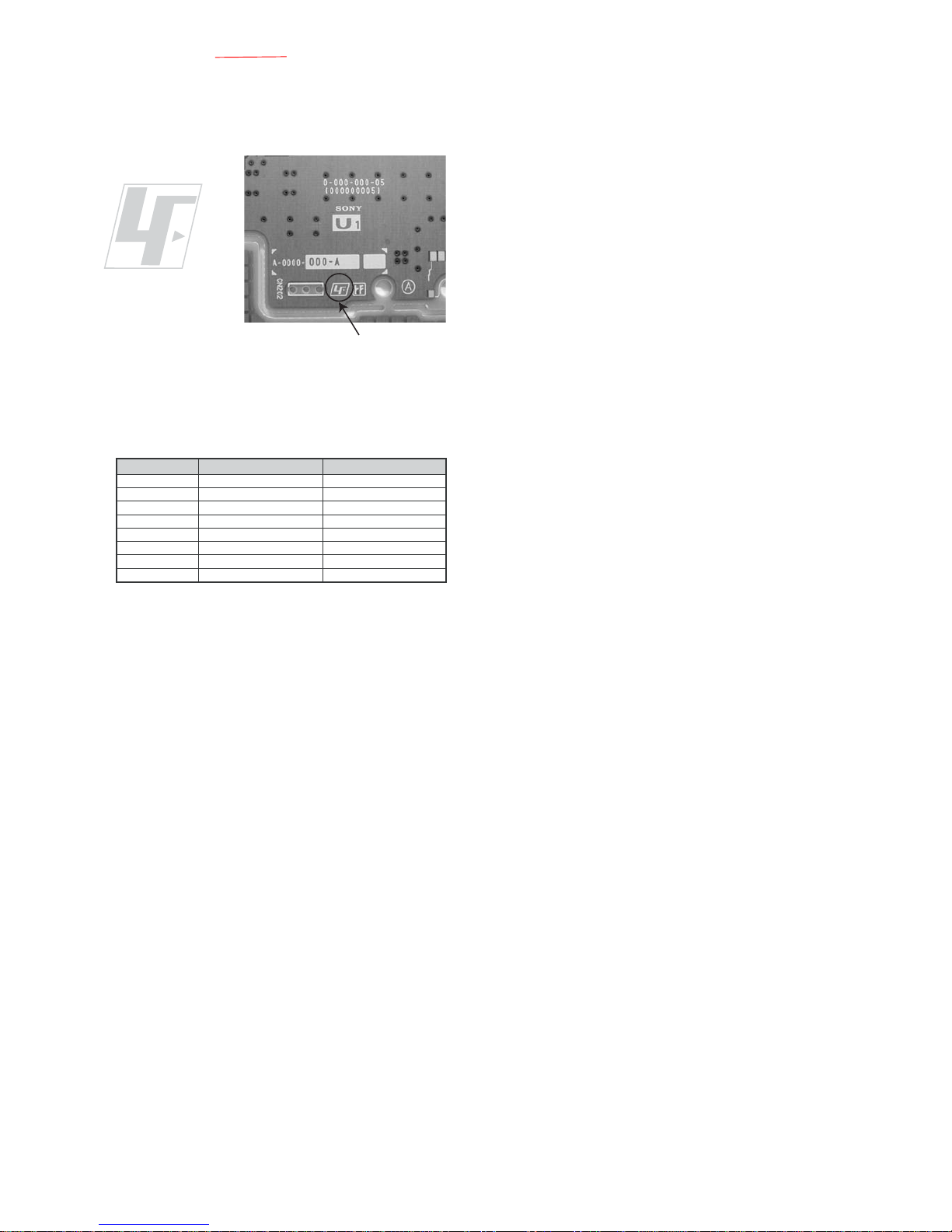
1-5. Lead Free Information
The circuit boards used in these models have been processed
using Lead Free Solder. The boards are identified by the LF
logo located close to the board designation.
The servicing of these boards requires special precautions. It
is strongly recommended to use Lead Free Solder material in
order to guarantee optimal quality of new solder joints. Lead
Free Solder is available under the following part numbers:-
Due to high melting point of Lead Free Solder, the soldering
iron tip temperature needs to be set to 370 degrees
centigrade. This requires soldering equipment capable of
accurate temperature control coupled with a good heat
recovery characteristics.
For more information on the use of Lead Free Solder,
please refer to
http://www.sony-training.com
rebmuntraP retemaiD skrameR
91-500-046-mm
m
m
m
m
m
m
m
3.0Kg52.0
02-500-046-7m4.0Kg05.0
12-500-046-7m5.0Kg05.0
22-500-046-7m6.0Kg52.0
32-500-046-7m8.0Kg00.1
42-500-046-7m0.1Kg00.1
52-500-046-7m2.1Kg00.1
62-500-046-7m6.1Kg00.1
7
Figure 2: LF logo
Figure 3: LF logo on circuit board

– 5 –
KLV-32S530A, 26, 32, 37 S550A
RM-GA016
RM-GA016W
SECTION 2
SELF DIAGNOSTIC FUNCTION
2.0 sec 2.0 sec
0.3 sec
0.3 sec
2-1. Overview of Control Buttons
LED Type Description
Remark
Status
Display
Power LED
Remark
POWER Green: One LED
Green lights at power ON.
STANDBY Red: One LED Red lights during standby.
Timer
Amber
: One LEDs
Amber lights
during Timer activation.
POWER ON Green lights OFF
in a normal state.
STANDBY
OFF Red lights
Microcomputer is
in a sleep state.
Failure
Classify the
trouble causes by
the no. of red
blinking.
Standby LED
Microcomputer is
2-2. LED Display Specification
2-3. LED Display Control
2-4. LED Pattern
When safety shutdown occurs, Standb y LED display reports the
cause by using the blinking patterns as indicated below.
Example:
The figure above shows LED display when
SHUTDOWN is caused by audio failure. It repeats
flashing for a specified number of times in 0.3sec/
cycle and has a 2 seconds interval of lighting off.
Please note that a 2 seconds interval of lighting off
is fixed regardless of abnormal state types.
2-5. Viewing the Service Diagnosis Display
1. While TV on standby mode, press the f ollowing sequence on
the Remote commander.
(if wrong key is pressed or passed 3 seconds during each
process, cancel entering the self-diagnosis display.)
2. To Exit, press the <I/1> key.
On screen
display
Channel 5
Volume (-)
POWER
Remote
sensor
Timer
indicator
Standby
indicator
Power
indicator
S E L F C H E C K
0 0 2 M A I N _ P O W E R _ E R R O R 0 0
0 0 4 5 V _ P O W E R _ E R R O R 0 0
0 0 6 B A C K _ L I G H T _ E R R O R 0 0
0 0 7 T E M P _ E R R O R 0 0
0 0 8 A U D I O _ E R R O R 0 0
1 2 3 4 5 - 0 9 8 7 6 - 0 1 2 3 4
12345: Total operation time by hour (0-65535)
09876: Boot count (0-65535)
01234: Panel operation time by hour (0-65535)
002: LED blinking times
MAIN_POWER_ERROR:
Detection name
00: Error Count (00-99)
PROG
Power
indicator
Channel
Volume
Input Select
Menu
– 6 –
KLV-32S530A, 26, 32, 37 S550A
RM-GA016
RM-GA016W
Blinking times Detection items Countermeasure
2 Main power failure Replace either/both z BT2 board
z G4T board (37”)
z GT3 board (26”/32”)
4 5V power failure Replace BT2 board.
8 Audio failure Replace either/board.
z BT2 board
z G4T board (37”)
z GT3 board (26”/32”)
z Speaker
z Woofer
6 Back light failure Replace either/board.
z BT2 board
z G4T board (37”)
z GT3 board (26”/32”)
7 Internal temperature Replace either/both z G4T board (37”)
failure z GT3 board (26”/32”)
2-6. STANDBY LED ERROR DISPLAY
Note: Each of the above blinking repeats every 2 seconds.
2-7. T riage Chart
Please refer page 46 for Triage Chart.

– 7 –
KLV-32S530A, 26, 32, 37 S550A
RM-GA016
RM-GA016W
SECTION 3
TROUBLE SHOOTING
Please refer page 47~50 for Trouble Shooting.
– 8 –
KLV-32S530A, 26, 32, 37 S550A
RM-GA016
RM-GA016W
4-1. KLV-26S550A
SECTION 4
DISASSEMBLY
4-1-4. GT3 Board Removal
4-1-2. Stand Assy Removal
4-1-5. BT2 Board Removal
4-1-3. Switch Unit Removal
4-1-1. Rear Cover Removal
4-1-6. Speaker and Bracket Removal
5 Lift to remove Rear Cover
1 Twelve screws
(BVTP2 4 X 16)
2 Two screws
(+PSW M3 X 5)
3 Two screws
(+BVTP 3 X 12)
4 Two screw
(+PSW M4 X 8)
2 Stand assy
1 Four screws
(+PSW M5 X 16)
3 Switch unit
1
2
Lift tabs to
remove board
3 GT3 board
2 Three connectors
1 Six screws
(+BVST 3 X 8)
6 BT2 board
8 Main Frame
3 Side Jack Bracket
5 Five connectors
7 Two screws
(+BVTP 3 X 12)
1 One screws
(+PSW M4 X 8)
2 Frame Spine
4 Nine screws
(+BVST 3 X 8)
5 Four screws
(+BVTP2 4 X 16)
9 Four screws
(+BVTP2 4 X 16)
3 One screw
(+BVTP2 4 X 16)
7 One screw
(+BVTP2 4 X 16)
qa Bezel assy
6 Loudspeaker (4 X 10cm)
4 Speaker Baffle
q; Loudspeaker (4 X 10cm)
8 Speaker Baffle
1 One screw
(+PSW M4 X 8)
2 Under Cover
Note:
1) The illustrations provided in this section might have slight difference from actual sets.
2) Refer to Removal & Installation of Rear Cover and Switch Unit Procedure in Section 1 Safety Notes.

– 9 –
KLV-32S530A, 26, 32, 37 S550A
RM-GA016
RM-GA016W
4-2. KLV-32S530A, 32S550A, 32S550A/L, 32S550A/T
4-2-2. Stand Assy Removal
4-1-8. LCD Panel Bezel Assy Removal
4-2-3. Switch Unit Removal
4-2-1. Rear Cover Removal
4-1-7. Vesa Frame Removal
4-2-4. GT3 Board Removal
5 One screw
(+BVTP 3 X 12)
6 HT1 Board
4 Frame Bottom
3 Frame Spine (R)
2 Two screws
(+PSW M4 X 8)
1 One screw
(+PSW M4 X 8)
2 Harness
with connector
3 LCD panel
4 Bezel assy
1 Two screws
(+BVTP2 4 X 16)
5 Lift to remove Rear Cover
1 Twelve screws
(BVTP2 4 X 16)
2 Two screw
(+PSW M3 X 5)
3 Three screws
(+BVTP 3 X 12)
4 Two screw
(+PSW M4 X 8)
2 Stand assy
1 Four screws
(+PSW M5 X 16)
3 Switch unit
1
2
Lift tabs to
remove board
3 GT3 board
2 Three connectors
1 Six screws
(+BVST 3 X 8)
– 10 –
KLV-32S530A, 26, 32, 37 S550A
RM-GA016
RM-GA016W
4-3. KLV-37S550A
4-2-8. LCD Panel Bezel Assy Removal
4-2-6. Speaker and Bracket Removal
4-3-1. Rear Cover Removal
4-2-7. Vesa Frame Removal
4-2-5. BT2 Board Removal
4-3-2. Stand Assy Removal
4 BT2 board
6 Main Bracket
1 Side Jack Bracket Assy
3 Five connectors
5 One screw
(+BVTP2 3 X 12)
2 Nine screws
(+BVST 3 X 8)
6 Four screws
(+BVTP2 4 X 16)
9 Four screws
(+BVTP2 4 X 16)
3 One screw
(+BVTP2 4 X 16)
7 One screw
(+BVTP2 4 X 16)
qa Bezel assy
5 Loudspeaker
(3.4 X 17.5cm)
4 Speaker Baffle
q; Loudspeaker (3.4 X 17.5cm)
8 Speaker Baffle
1 One screw
(+PSW M4 X 8)
2 Under Cover
qa One screw
(+BVTP 3 X 12)
qs HT1 Board
0 Frame Bottom
7 Frame Spine (R)
4 Frame Spine (L)
6 One screw
(+PSW M4 X 8)
9 One screw
(+PSW M4 X 8)
2 One screw
(+PSW M4 X 8)
1 One screw
(+PSW M4 X 8)
3 Two screws
(+BVTP 4 X 16)
5 One screw
(+PSW M4 X 8)
8 One screw
(+PSW M4 X 8)
2 Harness
with connector
3 LCD panel
4 Bezel assy
1 Two screws
(+BVTP2 4 X 16)
5 Lift to remove Rear Cover
1 Twelve screws
(BVTP2 4 X 16)
3 Two screws
(+PSW M3 X 5)
2 Two screws
(+BVTP 3 X 12)
4 Four screws
(+PSW 4 X 16)
2 Stand assy
1 Four screws
(+PSW M5 X 16)
– 11 –
KLV-32S530A, 26, 32, 37 S550A
RM-GA016
RM-GA016W
4-3-6. Speaker and Bracket Removal
4-3-4. G4T Board Removal
4-3-7. Vesa Frame Removal
4-3-5. BT2 Board Removal
4-3-3. Switch Unit Removal
4-3-8. LCD Panel Bezel Assy Removal
3 Switch unit
1
2
Lift tabs to
remove board
3 G4T board
2 Three connectors
1 Four screws
(+BVST 3 X 8)
4 BT2 board
6 Main Bracket
1 Side Jack Bracket Assy
3 Five connectors
5 One screw
(+BVTP2 3 X 12)
2 Nine screws
(+BVST 3 X 8)
5 Four screws
(+BVTP2 4 X 16)
9 Four screws
(+BVTP2 4 X 16)
3 One screw
(+BVTP2 4 X 16)
7 One screw
(+BVTP2 4 X 16)
qa Bezel assy
6 Loudspeaker
(3.4 X 17.5cm)
4 Speaker Baffle
q; Loudspeaker
(3.4 X 17.5cm)
8 Speaker Baffle
1 One screw
(+PSW M4 X 8)
2 Under Cover
0 One screw
(+BVTP 3 X 12)
qa HT1 Board
qs Guide Light
9 Frame Bottom
7 Frame Spine (R)
4 Frame Spine (L)
6 One screw
(+PSW M4 X 8)
3 Two screw
(+BVTP 4 X 16)
8 Two screws
(+BVTP2 4 X 16)
2 One screw
(+PSW M4 X 8)
1 One screw
(+PSW M4 X 8)
5 One screw
(+PSW M4 X 8)
2 Harness
with connector
3 LCD panel
4 Bezel assy
1 Four screws
(+BVTP2 4 X 16)
– 12 –
KLV-32S530A, 26, 32, 37 S550A
RM-GA016
RM-GA016W
SECTION 5
WIRE DRESSING
CAUTION :
1. Do not o verpull the wires during dressing
--> avoid disconnection of wires.
2. Make sure wires are kept away from
sharp edges, heatsinks & other
high-temperature parts.
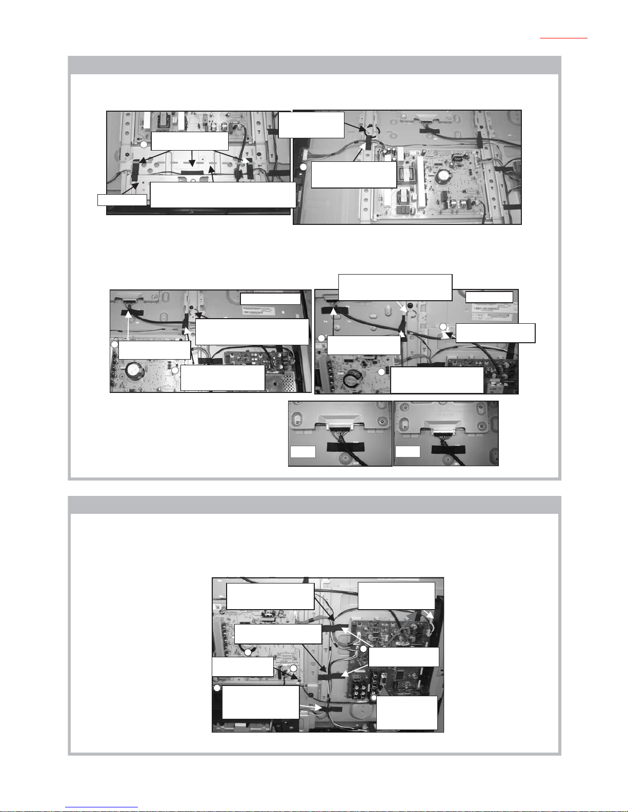
Legend:
Hook
5-1. KLV-26S550A
5-1-1. Wire Dressing overview.
5-1-2. Insert Connector Assy 10p and Speaker Connector Assy 4P.
P5-6
P4
P7
P4
P5-6
P8
Non CISPR model
1) Insert Connector Assy 10P to HT1 PWB. Attach HT1
PWB to Light Guide on Bezel.
2) Insert SP Conn Assy 4P to speaker as shown.
Attach Sheet Core, C (X1) as shown.
Left
speaker
3) Insert Connector Assy 10P to SW unit. Attach SW
unit to Bezel and dress with Tape (LCD) (X2).
CISPR model
Attach Sheet Core,
C to SP Conn Assy
4P; Lead Assy,
Earth and conn Assy
10P (X1). Use daturm
line to position
Sheet core, C.
Left
speaker
Conn Assy 10P
(HT1 PWB)
behind speaker
2
1
1
Dress Conn Assy
10P
(SW unit) using
Tape (LCD) (X2).

– 13 –
KLV-32S530A, 26, 32, 37 S550A
RM-GA016
RM-GA016W
5-1-3. Insert Connector Assy 14P
5-1-4. Attach Sheet Core, C (X3) to main bracket as shown.
A
1) Attach Sheet Core, C (X2) to frame bottom as shown.
2) Insert Conn Assy 14P to inverter and GT3 PWB as shown. Attach Sheet Core, C as shown.
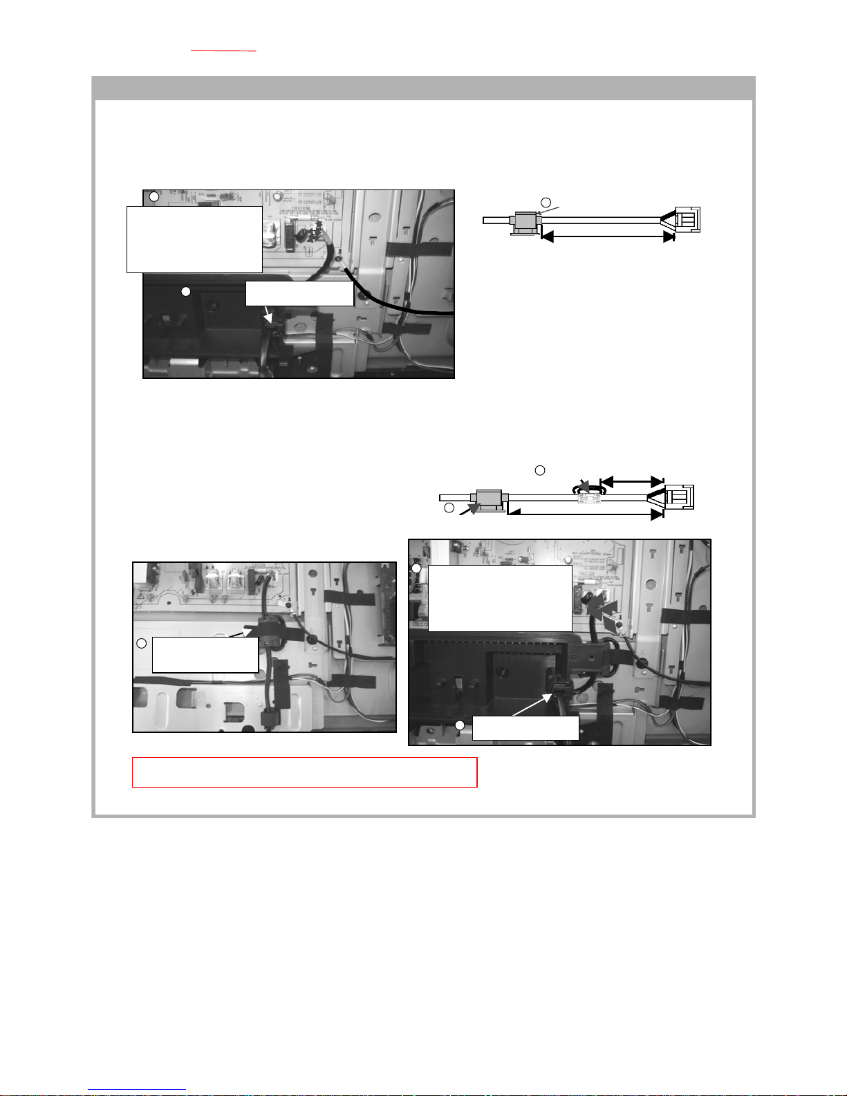
Note: When inserting LVDS harness to panel, make sure it is
fully inserted and in the correct direction as shown.
3) Attach Sheet Core, C (X2) to LVDS harness.
4) Attach Sheet Core, C to Connector Assy 14P
and LVDS harness.
3) Attach Tape, Shield followed by Sheet Core, C on to LVDS harness.
4) Insert screw on to earth clamp on LVDS harness.
5) Attach Sheet Core, C to Connector Assy 14P and LVDS harness.
6) Attach Sheet Core, C on to LVDS harness
For Non-CISPR models
For CISPR models
Attach Sheet Core, C to
LVDS harness.
Non-
CISPR
model
CISPR
model
NG
OK
Dress SP Conn Assy
4P to the left of this
line (edge of BT2 PWB)
Dress SP Conn Assy 4P; Lead
Assy, Earth and Conn Assy 10P
Wires along this path (behind Under cover)
and below raised area of frame bottom
Attach Sheet Core, C
towards the left side of
frame bottom.
Frame
bottom
Dress SP Conn Assy 4P and Conn
Assy 10P using Sheet Core, C. Use
datum line to position Sheet Core, C.
Attach Tape, Shield followed
by Sheet Core, C to LVDS
harness.
Attach Sheet Core, C to
Conn Assy 14P and LVDS
Insert screw on to
earth clamp on
LVDS harness.
Attach Sheet Core, C (X2) to
LVDS harness.
Attach Sheet Core, C to
conn Assy 14P and LVDS
harness
Attach Sheet Core, C to
Conn Assy 14P and SP
Conn Assy 4P.
Attach Sheet
Core, C to
main bracket
(X3).
Dress Conn Assy
10P;
Lead Assy, Earth
and
SP Conn Assy 4P
together.
Insert Conn Assy 14P to
GT3 PWB.
Attach Sheet Core, C (X1).
1
1
2
2
4
3
3
6
5
4
1

– 14 –
KLV-32S530A, 26, 32, 37 S550A
RM-GA016
RM-GA016W
5-1-5. Power Cord Wire Dressing
110 ± 5mm
AC Cord Holder
4m
4mm
m
70±
150 ± 5mm
AC Cord
Ferrite Core
4mm
4mm
1) Install AC cord holder to AC power cord at specified position
as shown.
2) Then install the AC power cord with holder on to under cover.
3) Lastly, dress AC power cord using pin, wire A6101 as shown.
4) Keep the AC power cord away from surrounding parts.
Non CISPR model
1) Install Ferrite core to AC power cord at specified position as shown.
2) Install AC cord holder to AC power cord at specified position as shown.
3) Attach Sheet Core, E to Ferrite Core and frame bottom.
4) Then install the AC power cord with holder on to under cover.
5) Lastly, dress AC power cord using pin, wire A6101 as shown.
6) Keep the AC power cord away from surrounding parts.
CISPR model
Make sure distance of
>4mm is kept from
F6102, C6102 and C6111
leads to single insulated
portion of AC power cord
(Blue and Brown wire).
This can be controlled by
using pin, wire A6101 to
dress AC power cord
away from conductive parts.
Make sure distance of >4mm is kept
from F6102, C6102 and C6111
leads to single insulated portion of
AC power cord (Blue and Brown
wire). This can be controlled by
using pin, wire A6101 to dress AC
power cord away from conductive parts.
Caution:
1. Ensure that AC power cord is not stressed whilst
inserting it into AC cord bracket.
Insert the AC cord holder on to
under cover
Dress AC
power cord
using pin,
wire A6101.
AC power
cord's wire is
facing to the
right
Attach Sheet
Core, E to Ferrite
Core.
Dress AC
power cord
using pin, wire
A6101.
Insert the AC cord
holder on to under
cover
4
2
3
3
5
6
4
1
2

– 15 –
KLV-32S530A, 26, 32, 37 S550A
RM-GA016
RM-GA016W
5-2-1. Wire Dressing overview .
5-2-2. Insert Connector Assy 10P and SP Connector Assy 4P
P3
P6
P4-5
P7
P3
P4-5
P8
P6
Non-CISPR model
Left Speaker
1) Insert Connector Assy 10P to HT1 PWB. Attach HT1 PWB
to Light Guide on Bezel.
2) Insert SP Conn Assy 4P to speaker as shown.
Attach Sheet Core, C (X1) as shown.
1) Insert Connector Assy 10P to SW unit. Attach SW unit to Bezel
and dress with Tape (LCD) (X2).
2) Insert SP Conn Assy to speaker and attach Sheet Core, C as shown.
3) Attach Sheet Core, C to Frame Bottom as shown.
Right Speaker
CISPR model
p
Left speaker
Right speaker
Attach Sheet Core, C to SP Conn Assy 4P
and Conn Assy 10P (X1). Use datum line
to position Sheet Core, C. Do not cover
speaker hole with Sheet Core, C.
1
2
1
2
3
Conn Assy 10P (HT1
PWB) behind speaker
Conn Assy 10P (HT1
PWB) behind speaker
Do not cover speaker
hole
Dress Conn Assy 10P
(SW unit) using Tape
(LCD) (X2).
Do not cover speaker hole
Attach Sheet Core, C to SP Conn Assy
4P
and Conn Assy 10P to Frame Bottom
Dress SP Conn Assy 4P and Conn Assy
10P using Sheet Core, C. Use datum line
to position Sheet Core , C.
5-2. KLV-32S530A, 32S550A, 32S550A/L, 32S550A/T
– 16 –
KLV-32S530A, 26, 32, 37 S550A
RM-GA016
RM-GA016W
5-2-3. Attach C Sheet Core and Insert Connector Assy 14P
5-2-4. Attach C Sheet Core to Main Bracket and Frame Bottom
OK
NG
2
w
1) Attach Sheet Core, C to frame bottom as shown.
2) Attach Sheet Core, C to main bracket as shown.
3) Insert Conn Assy 14P to inverter and GT3 PWB as shown. Attach Sheet Core, C as shown.
Note: When inserting LVDS harness to panel, make sure it is
fully inserted and in the correct direction as shown.
For all models
3) Attach Sheet Core, C to LVDS harness.
4) Attach Sheet Core, C to Connector Assy 14P and LVDS harness.
For CISPR models only
5) Insert screw on to earth clamp on LVDS harness.
1) Attach Sheet Core, C (X3) to main bracket as shown.
2) Attach Sheet Core, C (X1) to frame bottom as shown.
3) Attach Sheet Core, C (X1) to main bracket as shown.
Attach Sheet Core, C
to Main Bracket (X1).
CISPR model
Non-CISPR model
Attach Sheet Core, C (X1) to LVDS
harness.
Dress SP Conn
Assy 4P using
Sheet Core, C.
Attach Sheet Core, C to
Frame Bottom (X1).
Dress SP Conn Assy 4P; Lead
Assy, Earth and Conn Assy 10P
wires along this path (behind under
cover) and below raised area of
Frame Bottom.
Frame
Bottom
Dress Lead Assy, Earth
along this path
Attach Sheet Core, C (X1) to Conn Assy
14P and LVDS harness on frame spine.
Insert screw on to
earth clamp on LVDS
harness.
Attach Sheet Core, C (X1) to Conn
Assy 14P and LVDS harness on
frame spine.
Attach Sheet Core, C (X1) to
LVDS harness.
Dress SP Conn Assy 4P to
the left of this line (edge of
BT2 PWB)
Dress Conn
Assy 14P and
SP Conn Assy
4P together.
Dress Conn
Assy 10P and
SP Conn Assy
4P together.
Attach Sheet Core, C to
main bracket (X3).
Dress Lead Assy,
Earth to main bracket
using Sheet Core, C.
1
2
3
3
4
4
3
5
1
2
3
Dress SP Conn Assy 4P and
Conn Assy 10P together using
Sheet Core, C to frame bottom.
Insert Conn Assy 14P
to GT3 PWB.
Attach Sheet Core, C (X1)
– 17 –
KLV-32S530A, 26, 32, 37 S550A
RM-GA016
RM-GA016W
5-2-5. AC Power Cord Wire Dressing
150 ± 5mm
AC Cord Holder
4mm
4mm
110± 5mm
200 ± 5mm
AC Cord
Holder
Ferrite
Core
4mm
Non-CISPR model
1) Install AC cord holder to AC power cord at specified position as shown.
2) Then install the AC power cord with holder into under cover.
3) Lastly, dress AC power cord using pin, wire A6101 as shown.
4) Keep the AC power cord away from surrounding parts.
CISPR model
1) Install Ferrite core to AC power cord at specified position as shown.
2) Install AC cord holder to AC power cord at specified position as shown.
3) Then install the AC power cord with holder into under cover.
4) Attach Sheet Core, E to Ferrite Core. Place AC cord underneath frame spine.
5) Dress AC power cord using pin, wire A6101 as shown.
6) Lastly, keep the AC power cord away from surrounding parts.
Caution:
1. Ensure that AC power cord is not stressed whilst inserting it into
AC cord bracket.
Caution:
1. Ensure that AC power cord is not stressed whilst inserting it into
AC cord bracket.
Make sure distance of >4mm is kept
from F6102 and C6111 lead to single
insulated portion of AC power cord
(Blue and Brown wire). This can be
controlled by using pin, wire A6101 to
dress AC power cord away from
conductive parts.
Dress AC power cord using pin,
wire A6101. Keep AC cord away
from fuse F6102 (4mm or more).
Inset the AC Cord
Holder on to Under Cover.
Make sure distance of
>4mm is kept from F6102
and C6111 lead to single
insulated portion of AC
power cord (Blue and
Brown wire). This can be
controlled by using pin,
wire A6101 to dress AC
power cord away from
conductive parts.
Non-CISPR model
CISPR model
Dress AC power cord using
pin, wire A6101.
Attach Sheet Core,
E to Ferrite Core.
Insert the AC cord holder
on to under cover
AC cord is
underneath frame
spine.
3
2
1
4
5
3
6
2
1
– 18 –
KLV-32S530A, 26, 32, 37 S550A
RM-GA016
RM-GA016W
5-3. KLV-37S550A
5-3-1. Wire Dressing overview.
5-3-2. Insert Connector Assy 10P and SP Connector Assy 4P
5-3-3. Insert Connector Assy 10, SP Connector Assy and attach C Sheet Core
P3-4
P5-6P4
P3-4
P5-6
P4
Non-CISPR model
1) Insert Connector Assy 10P to HT1 PWB. Attach HT1 PWB to Light Guide on Bezel.
2) Insert SP Conn Assy 4P to speaker as shown.
Attach Sheet Core, C (X1) as shown.
1) Insert Connector Assy 10P to SW unit. Attach SW unit to Bezel and dress with Tape (LCD) (X2).
2) Insert SP Conn Assy to speaker and attach Sheet Core, C as shown.
3) Attach Sheet Core, C to panel as shown.
CISPR model
Left speaker
Right speaker
Attach Sheet Core, C to SP Conn Assy 4P
and Conn Assy 10P to panel. Dress wires towards
bottom of panel as shown.
Dress SP Conn Assy 4P and Conn Assy 10P using Sheet Core, C.
Use datum line to position Sheet Core, C. Do not cover speaker hole
with Sheet Core, C.
Conn Assy 10P (HT1 PWB)
behind speaker
Attach Sheet Core, C to SP Conn Assy 4P and Conn
Assy 10P. Use datum line to position Sheet Core, C.
Do not cover speaker hole with Sheet Core, C.
Keep wire away from screw
hole --> Prevent wire from
being sandwiched by screw
when docking rear cover.
Dress Conn Assy 10P
(SW unit) using
Tape (LCD) (X2).
Conn Assy 10P (HT1 PWB)
behind speaker
1
2
3
1
Do not cover speaker hole
Do not cover
speaker hole
– 19 –
KLV-32S530A, 26, 32, 37 S550A
RM-GA016
RM-GA016W
5-3-4. Attach C Sheet Core and Insert Connector Assy 14P
5-3-5. Attach C Sheet Core and Insert Connector Assy 14P
OK NG
1) Attach Sheet Core, C (X3) to frame bottom as shown.
2) Insert Conn Assy 14P to inverter and G4T PWB as shown. Attach Sheet Core, C as shown.
For all models
3) Attach Sheet Core, C to LVDS harness.
4) Attach Sheet Core, C to Connector Assy 14P and LVDS harness on frame spine.
For CISPR models only
5) Insert screw on to earth clamp on LVDS harness.
Note: When inserting LVDS harness to panel,
make sure it is fully inserted and in the
correct direction as shown.
1) Attach Sheet Core, C (X3) to main bracket as shown.
2) Attach Sheet Core, C (X1) to panel as shown.
3) Attach and screw Lead Assy, Earth on to G4T PWB as shown.
4) Attach Sheet Core, C (X1) to main bracket as shown.
Attach Sheet Core, C (X1)
to Conn Assy 14P and
LVDS harness.
Attach Sheet Core,
C to Lead Assy,
Earth on main
bracket.
Non-CISPR model
CISPR model
Attach Sheet Core, C to
frame bottom (X3).
Dress SP Conn Assy 4P and Conn Assy 10P
wires along this path (behind under cover) and
below raised area of bottom bracket.
Frame bottom
Do not cover screw
hole with Sheet
Core, C
Insert Conn Assy 14P to
G4T PWB.
Attach Sheet Core, C (X1).
Attach Sheet Core, C
(X1) to LVDS harness.
Do not cover screw hole with
Sheet Core, C. Keep LVDS harness
away from screw hole.
Attach Sheet Core, C
(X1) to LVDS harness.
Attach Sheet Core, C (X1) to
Conn Assy 14P and LVDS
harness.
Insert screw on to earth
clamp on LVDS harness.
Do not cover screw hole with
Sheet Core, C. Keep LVDS harness
away from screw hole.
Dress Conn Assy 10P and
SP Conn Assy 4P together.
Attach and screw
Lead Assy, Earth.
Dress SP Conn Assy 4P
and Conn Assy 10P
together using Sheet
Core, C to panel.
Attach Sheet Core, C
to main bracket (X3).
Attach Sheet Core, C to
Conn Assy 13P, Conn Assy
14P and SP Conn Assy 4P.
4
3
2
1
3
4
5
4
3
2
1
Dress SP Conn Assy
4P to the left of this line
(edge of BT2 PWB)
– 20 –
KLV-32S530A, 26, 32, 37 S550A
RM-GA016
RM-GA016W
5-3-6. Install AC Cord Holder and Power Cord
130 ±5mm
AC Cord Holder
4mm
4mm
70± 5mm
170 ± 5mm
AC Cord Holder
Ferrite Core
4mm
4mm
4mm
Non-CISPR model
1) Install AC cord holder to AC power cord at specified position as shown.
2) Then install the AC power cord with holder into under cover.
3) Keep the AC power cord away from surrounding parts.
CISPR model
1) Install Ferrite core to AC power cord at specified position as shown.
2) Install AC cord holder to AC power cord at specified position as shown.
3) Attach Sheet Core, E to Ferrite Core and frame bottom.
4) Then install the AC power cord with holder into under cover.
5) Keep the AC power cord away from surrounding parts.
Caution:
1. Ensure that AC power cord is not stressed whilst inserting it into AC cord bracket.
Make sure distance of >4mm is
kept from F101 and NR101 lead
to single insulated portion of AC
power cord (Blue and Brown
wire). Dress AC power cord
away from conductive parts.
Make sure distance of >4mm is
kept from F101 and NR101 lead
to single insulated portion of AC
power cord (Blue and Brown wire).
Dress AC power cord away from
conductive parts.
Insert the AC cord holder
on to under cover
Insert the AC cord holder
on to under cover
Attach Sheet Core, E to
Ferrite Core and Frame
Bottom.
3
1
2
5
4
3
2
1
– 21 –
KLV-32S530A, 26, 32, 37 S550A
RM-GA016
RM-GA016W
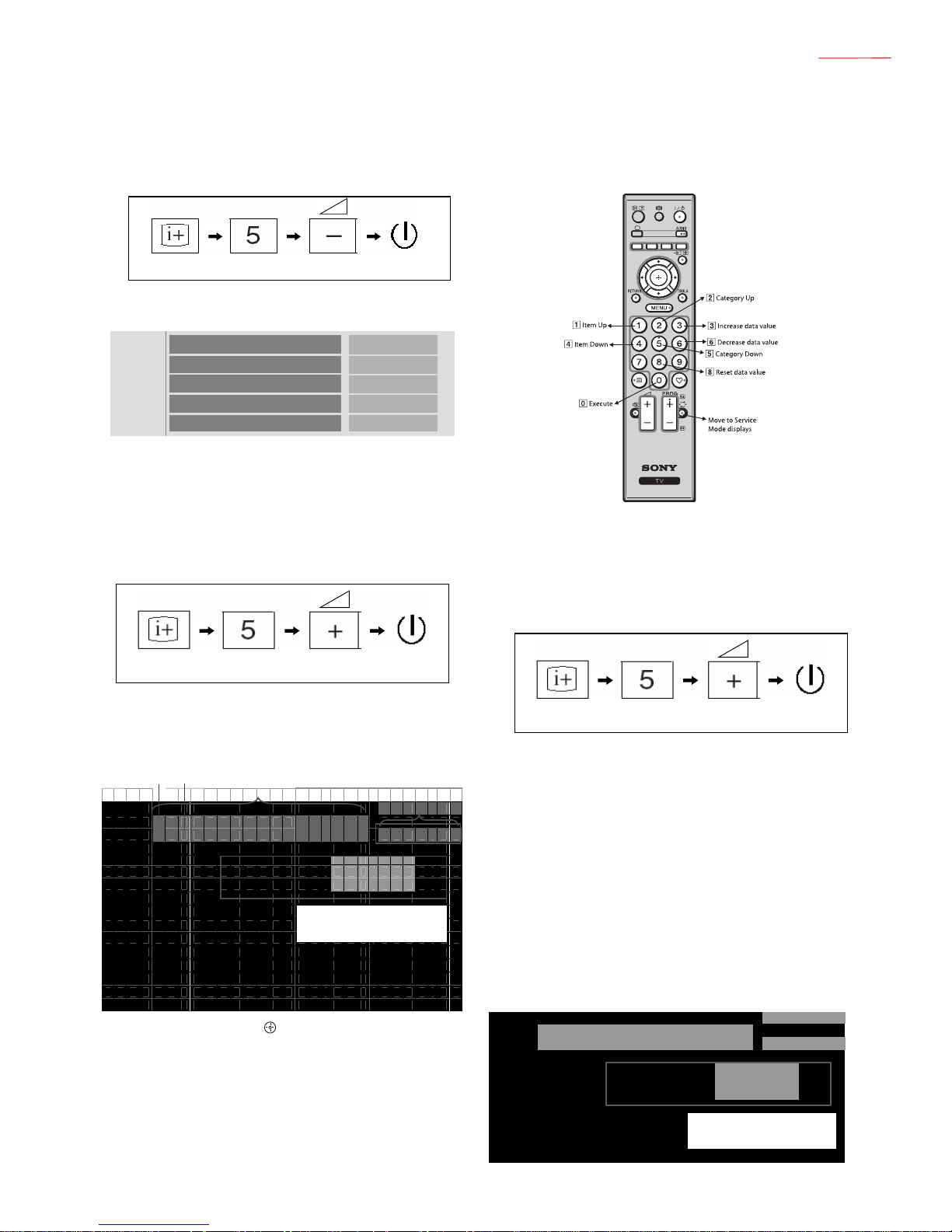
6-1. Accessing Diagnostic Menu
1. While TV set on standb y, press the following sequence on
the Remote commander (RMGA016).
The following menu will appear on the screen
2. To quit the diagnostic menu, turn off and on the set.
6-2. Viewing the Service Mode Display
1. While TV on standby mode, press the following sequence
on the Remote commander.
(if wrong key is pressed or passed 3 seconds during each
process, cancel entering the self-diagnosis display.)
Example on screen display:
2. To reset, press 8 – 0 – .
3. To Exit, press the <I/1> key .
SECTION 6
SERVICE ADJUSTMENTS
Figure 1
On screen
display
Channel 5
Volume (-)
POWER
MAIN_POWER_ERROR
5V_POWER_ERROR
AUDIO_ERROR
BALK_LIGHT_ERROR
TEMP_ERROR
0
0
0
0
0
6-3. Control keys via Remote Commander.
Buttons on the Remote Commander to access the service
menu items and adjust the data values.
6-4. Adjustment Method
6-4-1. Aging
1. While TV on standby mode , press the f ollowing sequence
on the Remote commander.
2. Select AGING with 2 or 5 On the Remote Commander.
3. Select AGING MODE with 1 or 4 On the Remote
Commander.
4. Select data value with 3 or 6 On the Remote
Commander to 1 to enable. Refer to Service Items
(Table 1) page 23.
5. Press <I/1> to exit.
6. When exit it will hav e the new data value and start aging.
7. Aging condition:
a) Supply voltage : Rating
b) Time: More than 20 minutes
c) Ambient Temp: 22-28 degrees
d) Input : Set no signal e xcept digital and analog
RF(Video/Component/PC)
Example on screen display:
On screen
display
Channel 5 Volume (+)
POWER
T V S E R V I C E
0 0 0 B M E
0 0 0 W P R _ 2 5 5
L O C T O P P R O G R A M :
G T V : M R 1 . 0 . 2
N V M : T D 0 . 1 0 0
PROGRAM: Show the Application version
GTV: Show the GTV Library version
NVM: Show the NVM version in the NVM data
(4bytes ASCII data)
[Data] Within 7 characters
[Category/Item name] Within 17
characters
T M 0 . 0 7 0
W
Categry Item
C
W
On screen
display
Channel 5 Volume (+)
POWER
PROGRAM: Show the Application versio
n
GTV: Show the GTV Library version
NVM: Show the NVM version in the NVM data
(4bytes ASCII data)
T V
0 0 0
0 0 0
L O C T O P
A G I N G
A G I N G
P R O G R A M :
G T V :
N V M :
M O D E
S E R V I C E
T M 0 . 0 7 0
M R 1 . 0 . 2
T D 0 . 1 0 0
1
 Loading...