

Sony KLV-32S400S, KLV-32S400A, KLV-37S400A, KLV-32S400H User Manual

REVISION HISTORY
NO. SUFFIX DATE SUPP / CORR DESCRIPTION
1 -01 2008/3 _ _ 1st Issue
2 -02 2008/4 _ _ New model addition. (Page 37)
EG1L (GA)
CHASSIS
MODEL
KLV-26S400A
KLV-32,32/H/S S400A
KLV-37S400A
PA RT NO. : 9-872-993-02
CHASSIS
LCD COLOR TV
SERVICE MANUAL
MODEL COMMANDER DEST.
KLV-26S400A
RM-GA011 E, EA, India, ME,
New Zealand,
Philippines,
Saudi Arabia,
South Africa, Thailand,
Vietnam
KLV-32S400A
RM-GA011 E, EA, India, Iran, ME,
New Zealand,
Philippines,
Saudi Arabia,
South Africa, Thailand,
Vietnam
MODEL COMMANDER DEST.
KLV-32S400A/H
RM-GA011 India, ME,
(Gun-Metallic Silver) Philippines,
South Africa,
Thailand
KLV-32S400A/S
RM-GA011 E, Saudi Arabia
(Silver)
KLV-37S400A
RM-GA011 E, EA, India,
Iran, ME,
New Zealand,
Philippines,
Saudi Arabia,
South Africa,
Thailand,
Vietnam
RM-GA011
KLV-26S400A KLV-32,32/H/S S400A KLV-37S400A
EG1L (GA)

– 2 –
KLV-26,32,32/H/S,37 S400A
RM-GA011
TABLE OF CONTENTS
1. SAFETY NOTES
1-1. Caution Handling of LCD Panel ..................................... 3
1-2. Safety Check Out ............................................................. 3
1-3. Leakage Test .................................................................... 3
1-4. WARNING ! .................................................................... 3
1-5. Lead Free Information ..................................................... 4
2. SELF DIAGNOSTIC FUNCTION
2-1. Overview of Control Buttons .......................................... 5
2-2. LED Display Specification.............................................. 5
2-3. LED Display Control ....................................................... 5
2-4. LED Pattern ..................................................................... 5
2-5. Standby LED Error Display ............................................ 6
3. DISASSEMBLY
3-1. Rear Cover Removal........................................................ 7
3-2. Stand Assy Removal ........................................................ 7
3-3. HG4 (KLV-26,32,32/H/S S400A) and
HG4A (KLV-37S400A) Boards Removal ....................... 8
3-4. BG1 Board Removal ....................................................... 8
3-5. GP Board Removal (KLV-26,32,32/H/S S400A) ........... 9
3-6. Power Unit (G2D) Board Removal (KLV-37S400A) ..... 9
3-7. Frame Removal ................................................................ 9
3-8. Speaker Removal ............................................................. 9
3-9. LCD Panel Removal ...................................................... 10
4. WIRE DRESSING
4-1. (KLV-26S400A) ............................................................. 11
4-2. (KLV-32,32/H/S S400A) ............................................... 14
4-3. (KLV-37S400A) ............................................................. 17
Section Title Page
5. SERVICE ADJUSTMENTS
5-1. Accessing Diagnostic Menu .......................................... 21
5-2. Aging ............................................................................ 21
5-3. Accessing Service Menu ............................................... 21
5-4. Resetting the User Menu- Factory Reset ...................... 22
5-5. White Balance Adjustment............................................ 22
5-6. Board & Panel Replacement ......................................... 23
6. DIAGRAMS
6-1. Block Diagram ............................................................... 24
6-2. Circuit Board Location .................................................. 24
6-3. Schematic Diagram ....................................................... 25
6-4. Printed Wiring Boards ................................................... 25
6-5. Semiconductor ............................................................... 25
7. EXPLODED VIEWS
7-1. (KLV-26S400A) ............................................................. 26
7-1-1. Rear Cabinet and Stand Assy ............................ 26
7-1-2. Chassis-1 ............................................................ 27
7-1-3. BG1, GP, HG4 Boards, Speakers,
Bezel Assy and LCD Panel ............................... 28
7-2. (KLV-32,32/H/S S400A) ............................................... 29
7-2-1. Rear Cabinet and Stand Assy ............................ 29
7-2-2. Chassis-1 ............................................................ 30
7-2-3. BG1, GP, HG4 Boards, Speakers,
Bezel Assy and LCD Panel ............................... 31
7-3. (KLV-37S400A) ............................................................. 32
7-3-1. Rear Cabinet and Stand Assy ............................ 32
7-3-2. Chassis-1 ............................................................ 33
7-1-3. BG1, Power Unit (G2D), HG4A Boards,
Speakers, Bezel Assy and LCD Panel ............... 34
8. ELECTRICAL PARTS LIST .............................................. 35
OPERATING INSTRUCTIONS
Section Title Page
– 3 –
KLV-26,32,32/H/S,37 S400A
RM-GA011
1-1. Caution Handling of LCD Panel
When installing the LCD Panel, make sure you are grounded
with a wrist band.
When installing the LCD Panel on the wall, the panel must be
secured using the 4 mounting holes on the rear cover.
1) Do not press the panel or frame edge to avoid the risk of
electric shock.
2) Do not scratch or press on the panel with any sharp
objects.
3) Do not leave the module in high temperature or in areas of
high humidity for an extended period of time.
4) Do not expose the LCD panel to direct sunlight.
5) Avoid contact with water. It may cause short circuit within
the module.
6) Disconnect the AC adapter when replacing the backlight
(CCFL) or inverter circuit. (High voltage occurs at the inverter
circuit at 650Vrms)
7) Always clean the LCD panel with a soft cloth material.
8) Use care when handling the wires or connectors of the
inverter circuit. Damaging the wires may cause a short circuit.
9) Protect the panel from ESD to avoid damaging the electronic circuit (C-MOS).
1-2. Safety Check-Out
After correcting the original service problem, perform the
following safety checks before releasing the set to the
customer:-
1) Check the area of your repair for unsoldered or poorly
soldered connections. Check the entire board surface for
solder splashes and bridges.
2) Check the interboard wiring to ensure that no wires are
"pinched" or contact high-wattage resistors.
3)Check all control knobs, shields, covers, ground straps and
mounting hardware have been replaced. Be absolutely certain
you have replaced all the insulators.
4) Look for unauthorized replacement parts, particularly
transistors that were installed during a previous repair. Point
them out to the customer and recommend their replacement.
5) Look for parts which, though functioning show obvious
signs of deterioration. Point them out to the customer and
recommend their replacement.
6) Check the line cords for cracks and abrasion.
Recommend the replacement of any such line cord to the
customer.
7) Check the antenna terminals, metal trim, "metallized"
knobs, screws and all other exposed metal parts for AC
leakage. Check leakage test as described next.
1-3. Leakage Test
The AC leakage from any exposed metal part to earth
ground and from all exposed metal parts to any exposed
metal part having a return to chassis must not exceed 0.5mA
(500 microamperes). Leakage current can be measured by
any one of the three methods:-
1. A commercial leakage tester such as the SIMPSON 229 or
RCA WT-540A. Follow the manufacturers instructions to use
those instructions.
2. A battery-operated AC milliampmeter. The DATA
PRECISION 245 digital multimeter is suitable for this job.
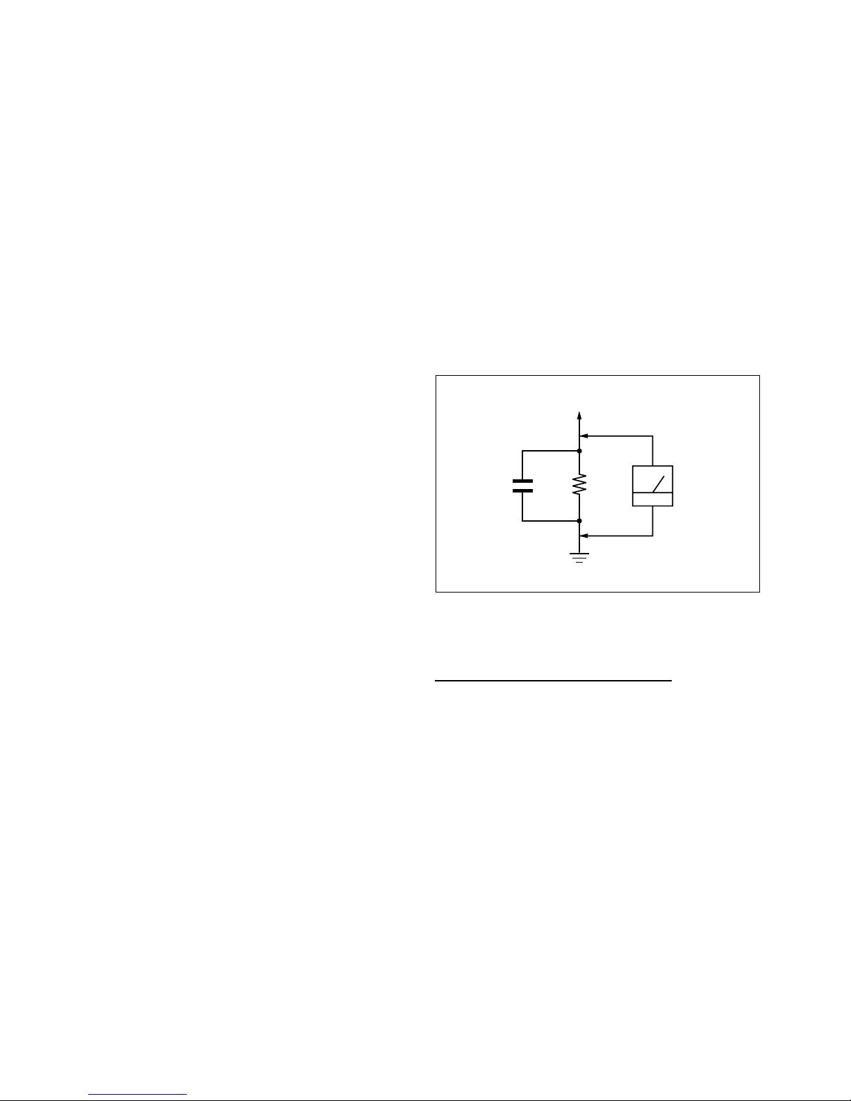
3. Measuring the voltage drop across a resistor by means of
a VOM or battery operated AC voltmeter. The 'limit' indication
is 0.75V so analog meters must have an accurate low voltage
scale. The SIMPSON'S 250 and SANWA SH-63TRD are
examples of passive VOMs that are suitable. Nearly all battery
operated digital multimeters that have a 2 VAC range are
suitable. (see Figure 1.)
1.5 k
Ω
0.15 µF
AC
Voltmeter
(0.75 V)
To Exposed Metal
Parts on Set
Earth Ground
SECTION 1
SAFETY NOTES
Figure 1. AC voltmeter to check AC leakage
1-4. WARNING !
SAFETY-RELATED COMPONENT WARNING!
COMPONENTS IDENTIFIED BY SHADING AND MARK !
ON THE EXPLODED VIEWS ARE CRITICAL FOR SAFE
OPERATION. REPLACE THESE COMPONENTS WITH
SONY PARTS WHOSE PART NUMBERS APPEAR AS
SHOWN IN THIS MANUAL OR IN SUPPLEMENTS
PUBLISHED BY SONY. CIRCUIT ADJUSTMENTS THAT ARE
CRITICAL FOR SAFE OPERATION ARE IDENTIFIED IN
THIS MANUAL. FOLLOW THESE PROCEDURES
WHENEVER CRITICAL COMPONENTS ARE REPLACED
OR IMPROPER OPERATION IS SUSPECTED.
– 4 –
KLV-26,32,32/H/S,37 S400A
RM-GA011
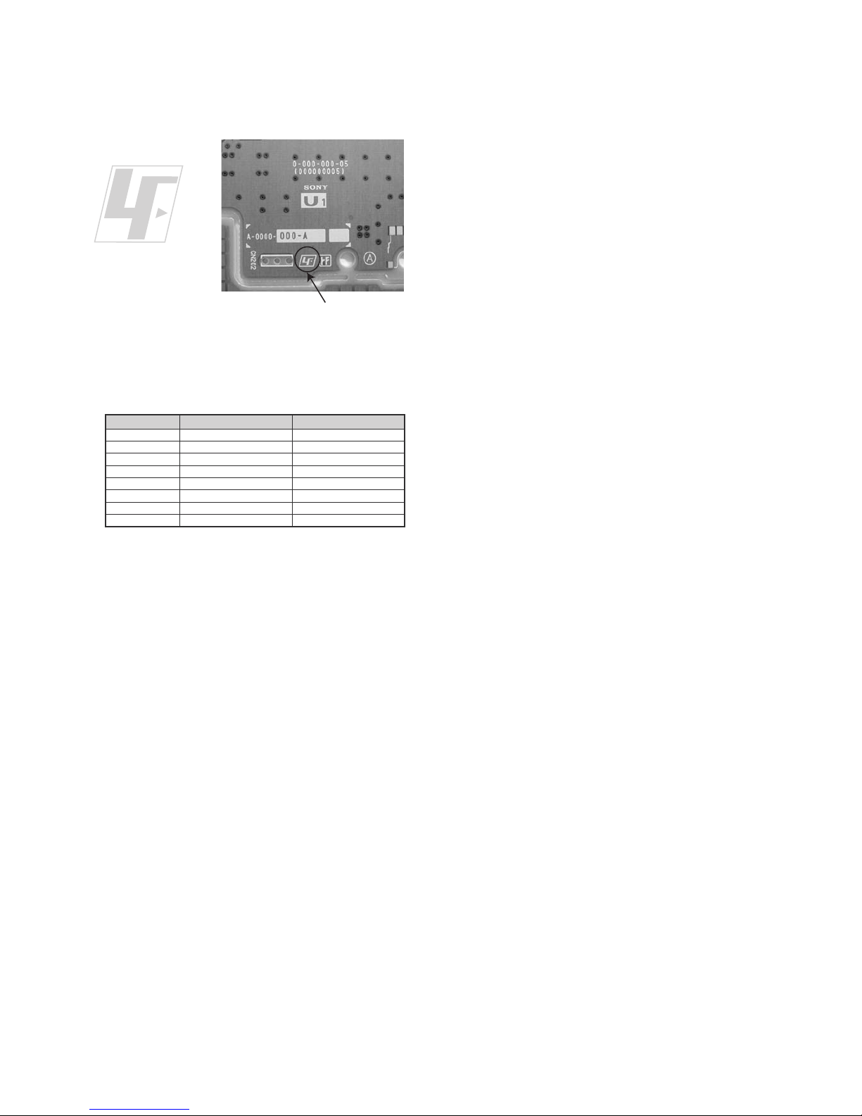
1-5. Lead Free Information
The circuit boards used in these models have been processed
using Lead Free Solder. The boards are identified by the LF
logo located close to the board designation.
The servicing of these boards requires special precautions. It
is strongly recommended to use Lead Free Solder material in
order to guarantee optimal quality of new solder joints. Lead
Free Solder is available under the following part numbers:-
Due to high melting point of Lead Free Solder, the soldering
iron tip temperature needs to be set to 370 degrees
centigrade. This requires soldering equipment capable of
accurate temperature control coupled with a good heat
recovery characteristics.
For more information on the use of Lead Free Solder,
please refer to
http://www.sony-training.com
rebmuntraP retemaiD skrameR
91-500-046-mm
m
m
m
m
m
m
m
3.0Kg52.0
02-500-046-7m4.0Kg05.0
12-500-046-7m5.0Kg05.0
22-500-046-7m6.0Kg52.0
32-500-046-7m8.0Kg00.1
42-500-046-7m0.1Kg00.1
52-500-046-7m2.1Kg00.1
62-500-046-7m6.1Kg00.1
7
Figure 2: LF logo
Figure 3: LF logo on circuit board

– 5 –
KLV-26,32,32/H/S,37 S400A
RM-GA011
PICTURE OFF/
TIMER
REMOTE/LIGHT SENSORSTANDBY POWER
MENU TV/VIDEO VOLUME CHANNEL
POWER
SECTION 2
SELF DIAGNOSTIC FUNCTION
2-4. LED Pattern
When safety shutdown occurs, Standby LED display reports the
cause by using the lightning patterns as indicated below.
Example:
The figure above shows LED display when
SHUTDOWN is caused by DC_ALERT 2. It repeats
flashing for a specified number of times in 0.3sec/
cycle and has a 2 seconds interval of lighting off.
Please note that a 2 seconds interval of lighting off
is fixed regardless of abnormal state types.
2.0 sec 2.0 sec
0.3 sec
0.3 sec
2-1. Overview of Control Buttons
LED Typ e Description
Remark
Status
Display
Power LED
Remark
POWER Green: LED
Green lights at power ON.
STANDBY Red: One LED Red lights during standby.
Timer
Green/Amber
: Two LEDs
Green lights during Picture
OFF and amber lights
during Timer activation.
POWER ON Green lights OFF
in a normal state.
STANDBY
OFF Red lights
Microcomputer is
in a sleep state.
Failure
Classify the
trouble causes by
the no. of red.
Standby LED
Microcomputer is
2-2. LED Display Specification
2-3. LED Display Control
– 6 –
KLV-26,32,32/H/S,37 S400A
RM-GA011
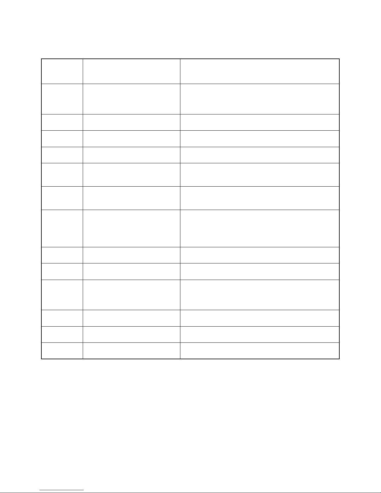
Blinking times Error Countermeasure
2 DC_DET (12V Main Voltage) Replace either/both z BG1 board
z GP(26",32")/
Power Unit(G2D)(37") board
3 DC_ALERT 1 Replace BG1 board.
4 DC_ALERT 2 Replace BG1 board.
5 DC_ALERT 3 Replace BG1 board.
6BACKLIGHT/ Replace BG1 board.
INVERTER ERROR
7 INTERNAL TEMP Replace GP(26",32")/Power Unit(G2D)(37") board
ERROR
8AUDIO ERROR Replace either/both z BG1 board
z GP(26",32")/
Power Unit(G2D)(37") board
z Speaker
9 Not used for GA —
10 Not used for GA —
11 NVM ERROR Replace either/both z BG1 board
z GP(26",32")/
Power Unit(G2D)(37") board
12 IIC ERROR Replace BG1 board.
13 BALANCER ERROR Replace BG1 board.
14 HDMI ERROR —
2-5. Standby LED Error Display
Perform below countermeasures according to Standby LED blinking times.
Note: Each of the above blinking repeats every 2 seconds.
– 7 –
KLV-26,32,32/H/S,37 S400A
RM-GA011
SECTION 3
DISASSEMBLY
(KLV-26S400A)
(KLV-32,32/H/S S400A) (KLV-32,32/H/S S400A)
(KLV-37S400A)
(KLV-26S400A)
(KLV-37S400A)
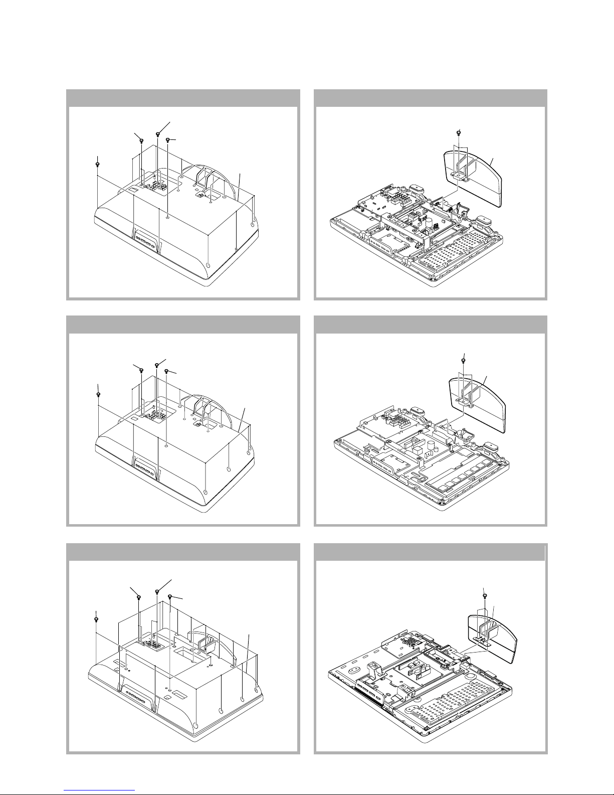
3-1. Rear Cover Removal
3-2. Stand Assy Removal
4 Two screws
(+PSW M3 X 5)
5 Lift to remove
Rear Cover
3 One screw
(+PSW M5 X 8)
1 Fifteen screws
(+BVTP2 4 X 16)
2 Two screws
(+BVTP 3 X 12)
4 Two screws
(+PSW M3 X 5)
5 Lift to remove
Rear Cover
3 One screw
(+PSW M5 X 8)
1 Sixteen screws
(BVTP2 4 X 16)
2 Two screws
(+BVTP 3 X 12)
5 Lift to remove
Rear Cover
1 Seventeen screws
(+BVTP2 4 X 16)
2 Four screws
(+PSW M5 X 12)
3 Two screws
(+BVTP 3 X 12)
4 Two screws
(+PSW M3 X 5)
2 Stand assy
1 Three screws
(+PSW M5 X 16)
2 Stand assy
1 Three screws
(+PSW M5 X 16)
2 Stand assy
1 Three screws
(+PSW M5 X 20)
– 8 –
KLV-26,32,32/H/S,37 S400A
RM-GA011
(KLV-32,32/H/S S400A)
(KLV-37S400A)
(KLV-26S400A)
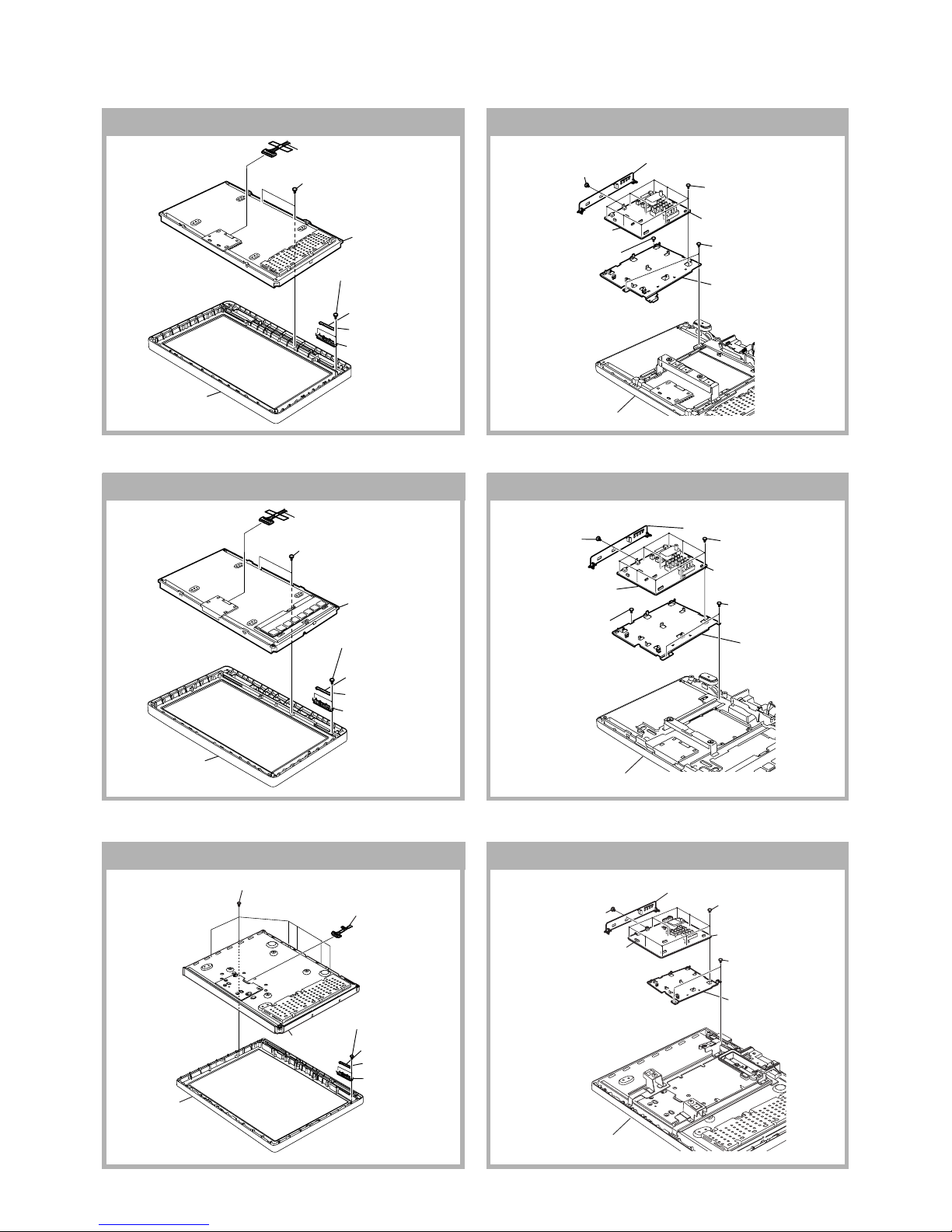
3-3. HG4 and HG4A Boards Removal 3-4. BG1 Board Removal
(KLV-32,32/H/S S400A)
(KLV-37S400A)
(KLV-26S400A)
2 Harness
with connector
6 HG4 board
4 One connector
Guide Light
3 LCD panel
Bezel assy
1 Two screws
(+BVTP2 4 X 16)
5 Two screws
(+BVTP2 3 X 12)
1 Six screws
(+BVTP2 4 X 16)
3 LCD panel
2 Harness
with connector
Bezel assy
6 HG4A board
4 One connector
Guide Light
5 Two screws
(+BVTP2 3 X 12)
2 Harness
with connector
6 HG4 board
4 One connector
Guide Light
3 LCD panel
Bezel assy
1 Two screws
(+BVTP2 4 X 16)
5 Two screws
(+BVTP2 3 X 12)
Main Bracket
4 BG1 board
3 Six connectors
5 One screw
(+BVST 3 X 8)
Two screws
(+BVST 3 X 8)
2 Nine screws
(+BVST 3 X 8)
1 One screw
(+PSW M3 X 5)
Bracket Side Jack Assy
Bezel assy
Main Bracket
4 BG1 board
3 Six connectors
5 One screw
(+BVST 3 X 8)
Two screws
(+BVST 3 X 8)
2 Nine screws
(+BVST 3 X 8)
1 One screw
(+PSW M3 X 5)
Bracket Side Jack Assy
Bezel assy
Main Bracket
Bezel assy
4 BG1 board
3 Six connectors
Two screws
(+BVST 3 X 8)
2 Nine screws
(+BVST 3 X 8)
1 One screw
(+PSW M3 X 5)
Bracket Side Jack Assy
– 9 –
KLV-26,32,32/H/S,37 S400A
RM-GA011
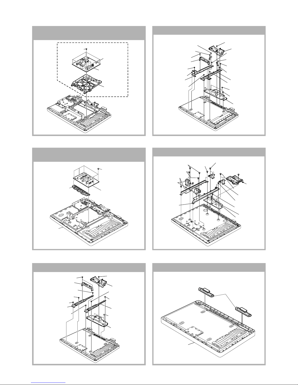
3-6. Power Unit (G2D) Board Removal
(KLV-37S400A)
(KLV-26S400A)
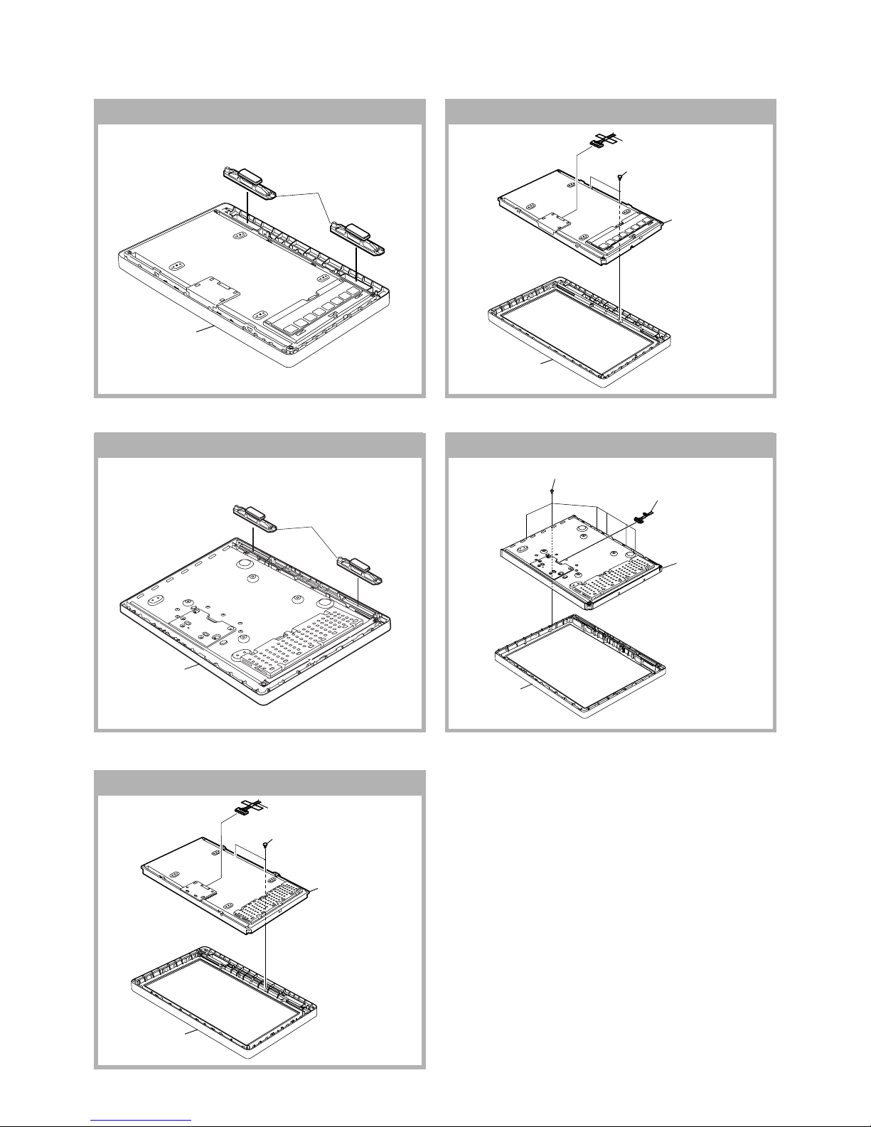
3-7. Frame Removal
(KLV-37S400A)
(KLV-26S400A)
(KLV-32,32/H/S S400A)
3-8. Speaker Removal
3 GP board
G1 Bracket
2 One connector
1 Four screws
(+PSW 3SG)
1 Power Unit (G2D Board)
3 G2 Bracket, Upper
Bezel Assy
2 Six screws
(+BVST 3 X 8)
5 One screw
(+BVTP2 4 X 16)
6 Two screws
(+BVTP2 4 X 16)
Frame Bottom
Frame Spine (R)
Cover Under
Frame Spine (L)
Vesa Frame (Top) Assy
3 One screw
(+PSW M4 X 8)
3 One screw
(+PSW M4 X 8)
1 One screw
(+BVTP2 4 X 16)
2 Two screws
(+PSW M4 X 8)
4 One screw
(+PSW M4 X 8)
5 One screw
(+BVTP2 4 X 16)
4 One screw
(+PSW M4 X 8)
4 One screw
(+PSW M4 X 8)
5 One screw
(+PSW M4 X 8)
9 Four screws
(+PSW M4 X 8)
8 Two screws
(+BVTP2 4 X 16)
3 One screw
(+PSW M4 X 8)
4 One screw
(+PSW M4 X 8)
3 One screw
(+PSW M4 X 8)
1 Two screws
(+BVTP2 4 X 16)
2 Two screws
(+PSW M4 X 8)
6 One screw
(+PSW M4 X 8)
7 One screw
(+BVTP2 4 X 16)
7 One screw
(+BVTP2 4 X 16)
5 One screw
(+PSW M4 X 8)
6 One screw
(+PSW M4 X 8)
Frame Bottom
Frame Spine (32R)
Cover Under
Frame Spine (32L)
Vesa Frame (Top) Assy
1 One screw
(+BVTP2 4 X 16)
7 Two screws
(+BVTP2 4 X 16)
8 One screw
(+PSW M4 X 8)
5 Four screws
(+PSW M4 X 8)
4 Two screws
(+PSW M4 X 8)
6 Two screws
(+BVTP2 4 X 16)
2 Three screws
(+PSW M4 X 8)
2 Three screws
(+PSW M4 X 8)
3 Two screws
(+PSW M5 X 8)
3 Two screws
(+PSW M5 X 8)
Frame Bottom
Vesa Frame
(Bottom) Assy
Cover Under
Frame Spine
(37L)
Frame Spine
(37R)
Vesa Frame
(Top) Assy
Speaker
Bezel assy
3-5. GP Board Removal
(KLV-26,32,32/H/S S400A)
– 10 –
KLV-26,32,32/H/S,37 S400A
RM-GA011
(KLV-37S400A)
(KLV-26S400A)
(KLV-32,32/H/S S400A)
3-9. LCD Panel Removal
(KLV-37S400A)
(KLV-32,32/H/S S400A)
Speaker
Bezel assy
Speaker
Bezel assy
2 Harness
with connector
3 Lift to remove
LCD panel
Bezel assy
1 Two screws
(+BVTP2 4 X 16)
2 Harness
with connector
3 Lift to remove
LCD panel
Bezel assy
1 Two screws
(+BVTP2 4 X 16)
2 Six screws
(+BVTP2 4 X 16)
3 Lift to remove
LCD panel
1 Harness
with connector
Be
zel assy
– 11 –
KLV-26,32,32/H/S,37 S400A
RM-GA011
SECTION 4
WIRE DRESSING
CAUTION :
1. Do not overpull the wires during dressing
--> avoid disconnection of wires.
2. Make sure wires are kept away from
sharp edges, heatsinks & other
high-temperature parts.
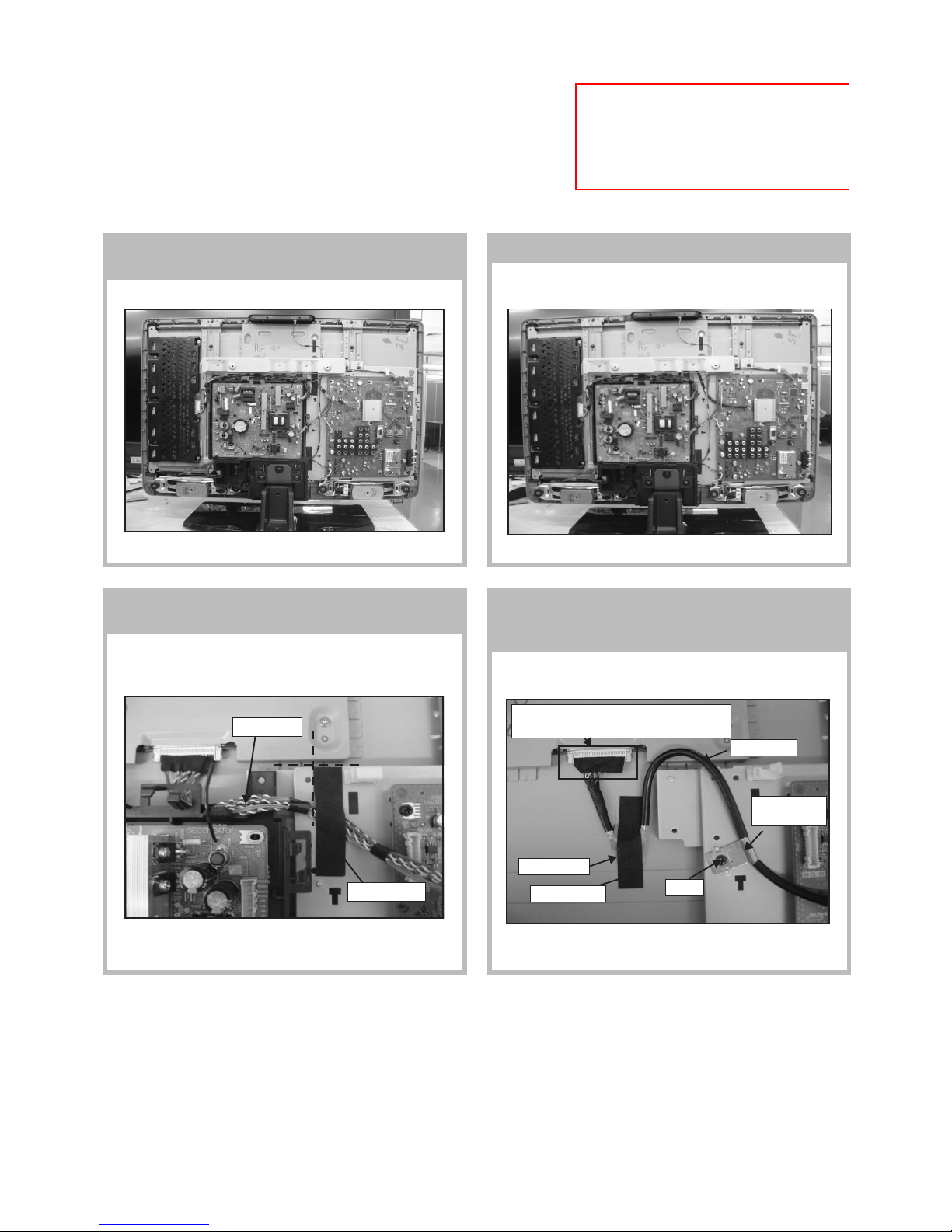
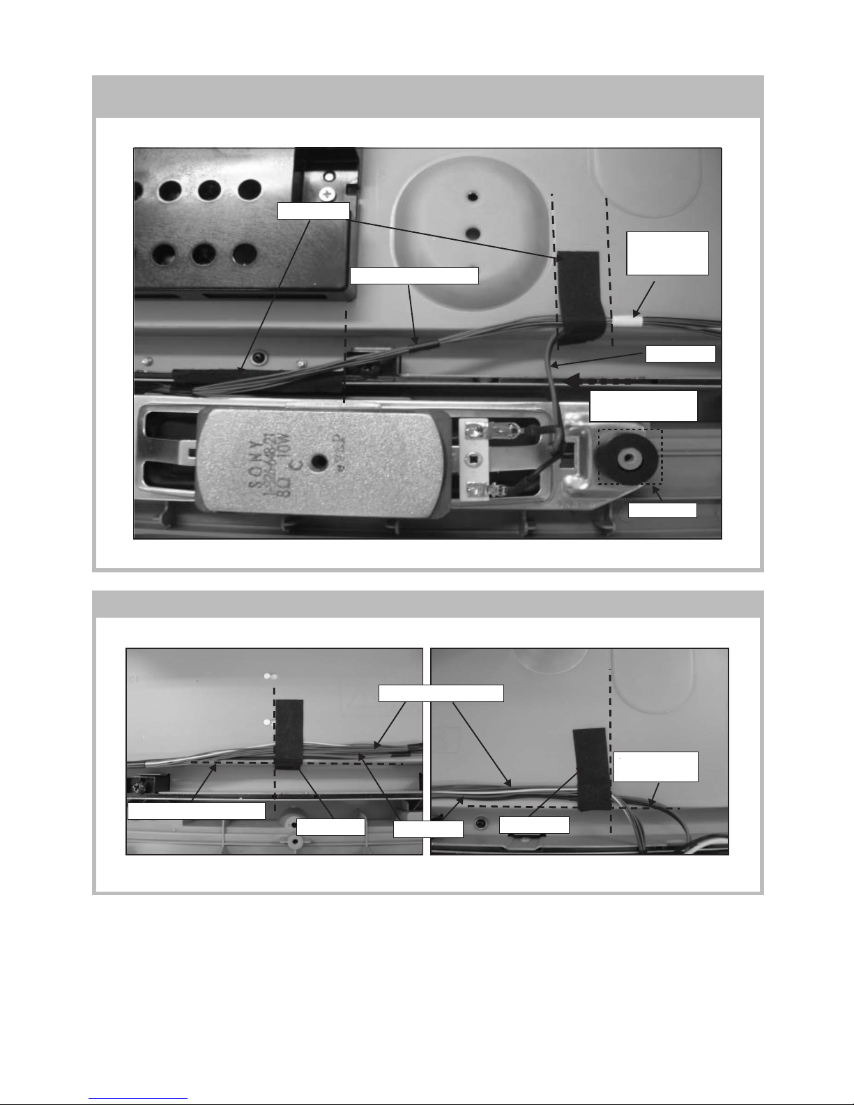
4-1-1. Wire Dressing Overview for
Non-CISPR model.
4-1-2. Wire Dressing Overview for CISPR model.
4-1-3. Dress LVDS cable with Sheet Core C.
(For Non-CISPR model)
4-1-4. Dress LVDS cable with Sheet Core C &
Shield Tape and screw LVDS cable's clamp
on main bracket. (For CISPR model)
4-1.(KLV-26S400A)
Sheet Core C
LVDS cable
Datum
Datum
Sheet Core C
LVDS cable
Shield Tape
LVDS cable's
clamp
Screw
Make sure LVDS connector fully inserted
with correct direction as shown.
– 12 –
KLV-26,32,32/H/S,37 S400A
RM-GA011
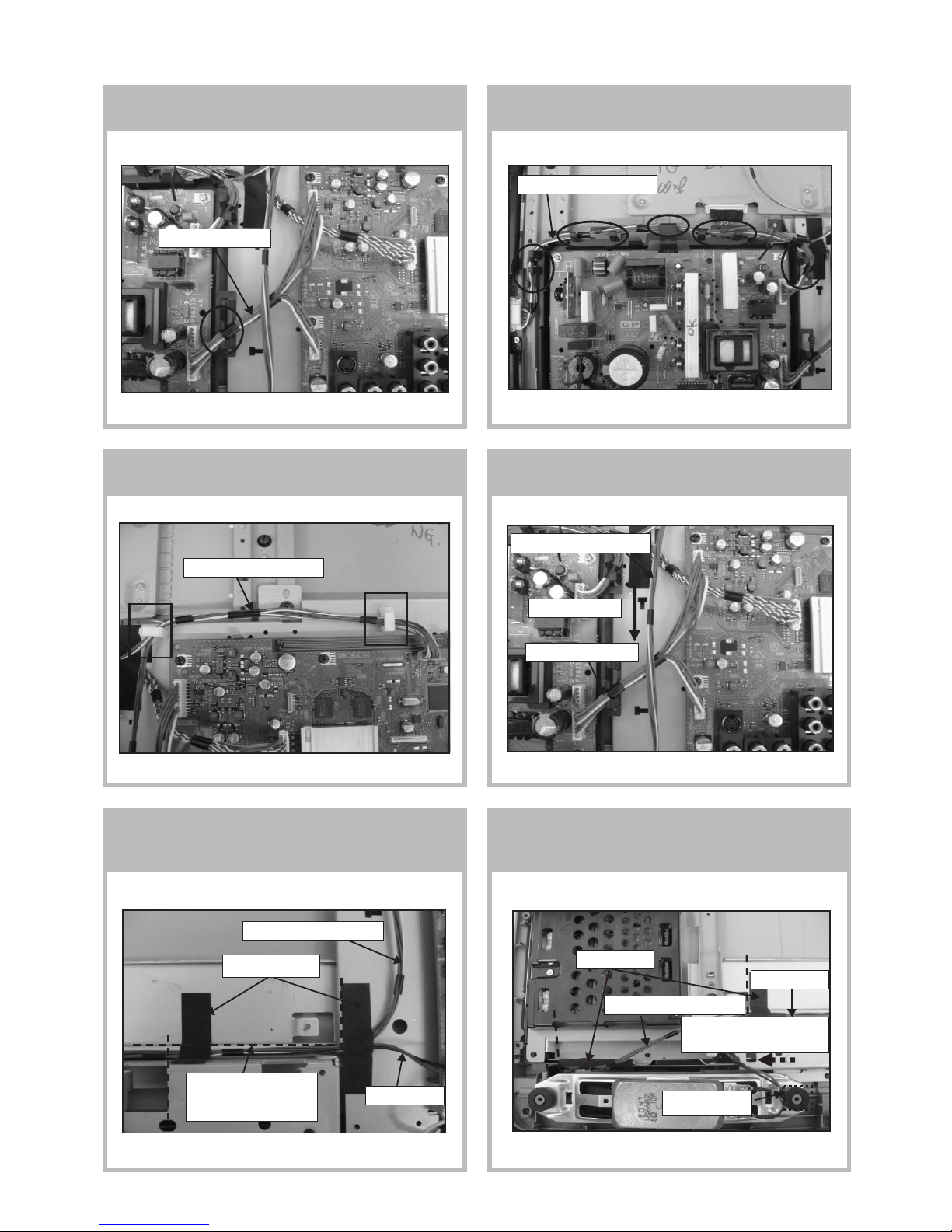
4-1-5. Dress Connector Assy 13P at
G1 bracket's hook,
4-1-6. Dress Connector Assy 14P+20P at
G1 bracket's hook.
4-1-7. Dress Connector Assy 14P+20P with
Slide Clamp (quantity: 2)
4-1-8. Dress Connector Assy 14P+20P on top of
Connector Assy.
4-1-9. Dress Connector Assy 14P+20P &
Speaker Wire with Sheet Core C
(quantity: 2).
4-1-10. Apply Sheet Core C on LCD panel and
dress Connector Assy 14P+20P &
Speaker Wire with Sheet Core C.
Connector assy 14P+20P
Sheet Core C
Connector assy 14P+20P
Speaker Wire
Datum
Caution:
Make sure wire not over
this line.
Datum
Connector assy 13P
Connector assy 14P+20P
Connector assy 14P+20P
Pull wire straight
Connector assy 13P
Datum
Datum
Sheet Core C
Speaker Wire
Connector assy 14P+20P
Caution : Pull away from
screw boss
Screw boss
Datum

– 13 –
KLV-26,32,32/H/S,37 S400A
RM-GA011
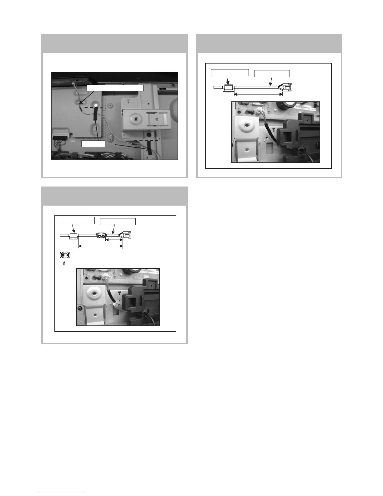
4-1-11. Dress Speaker Wire(L) with LCD tape. 4-1-12. Dress Connector Assy 14P+20P with
LCD tape.
4-1-13. Install AC Cord Holder on AC Power Cord.
(For Non-CISPR model)
4-1-14. Install AC Cord Holder on AC Power Cord.
(For CISPR model)
Speaker Wire
Caution : Pull away from screw boss
Screw boss
Datum
LCD tape
130mm
AC Power Cord
AC Cord holder
AC Power Cord
130mm
70mm
Ferrite Core
Cable tie
Note: Make sure
tighten cable tie and
cut excess part.
Connector assy 14P+20P
Datum
LCD tape
AC Cord holder
– 14 –
KLV-26,32,32/H/S,37 S400A
RM-GA011
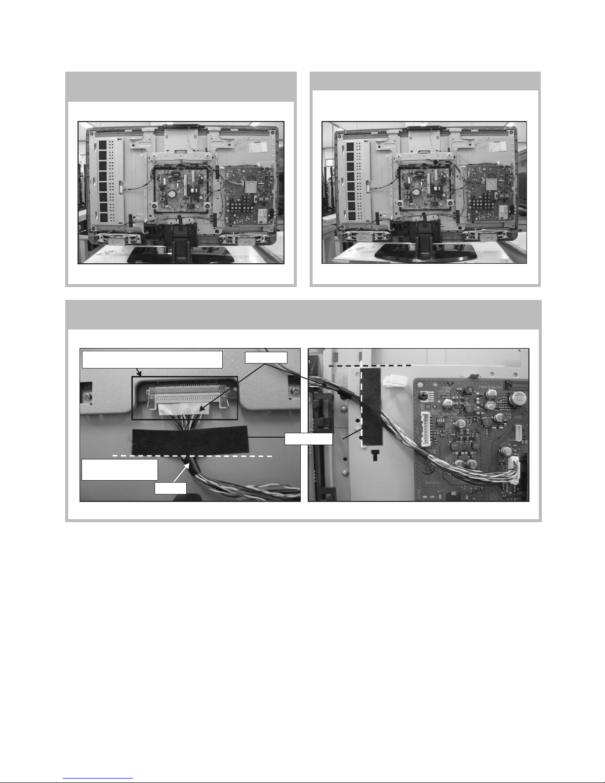
4-2-1. Wire Dressing Overview for
Non-CISPR model
4-2-2. Wire Dressing Overview for CISPR model
4-2-3. Dress LVDS Cable with Sheet Core C (quantity: 2).
(For Non-CISPR model)
4-2. (KLV-32,32/H/S S400A)
Use UL tape
Use UL tape
location as guide line
Make sure LVDS connector fully inserted
with correct direction as shown.
LVDS cable
Sheet Core C
Datum
Datum
Datum
UL Tape

– 15 –
KLV-26,32,32/H/S,37 S400A
RM-GA011
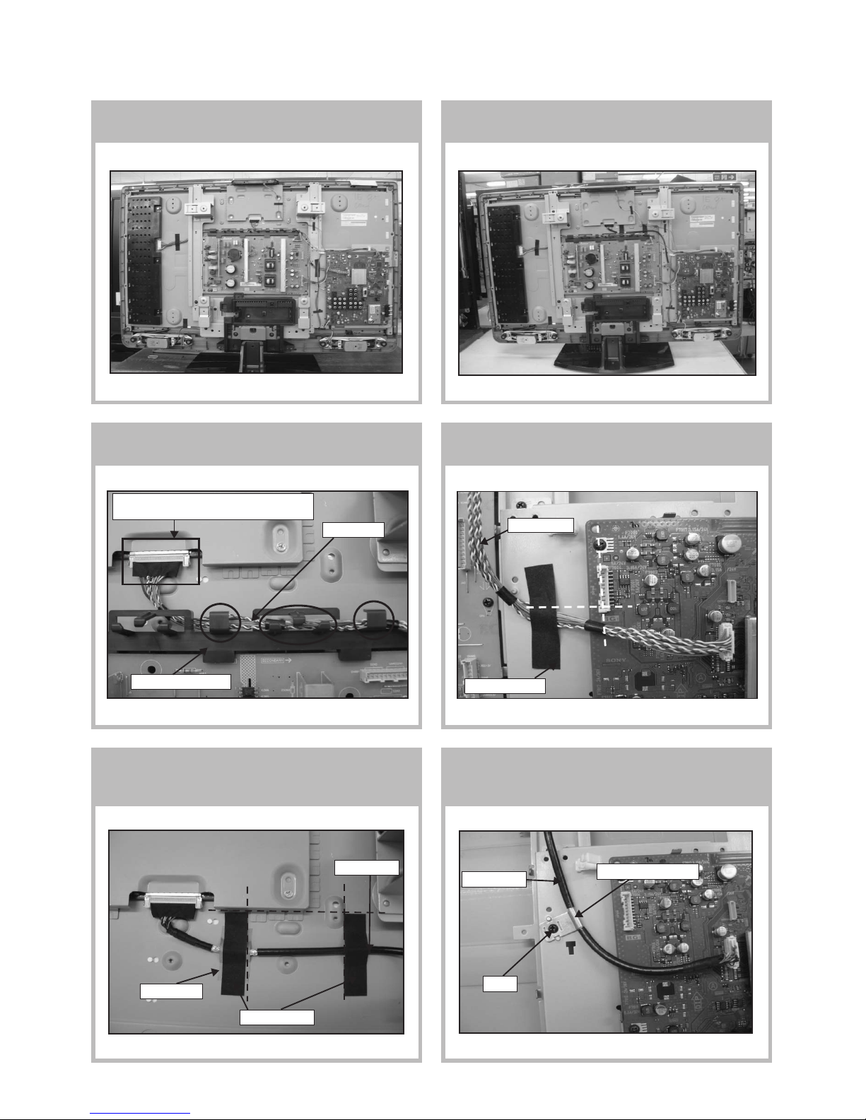
4-2-4. Dress LVDS cable with Sheet Core C &
Shield Tape. (For CISPR model)
4-2-5. Screw LVDS cable's clamp on main bracket.
(For CISPR model)
4-2-6. Dress Connector Assy 13P at
G1 Bracket's hook.
4-2-7. Dress Connector Assy 14P + 20P at
Bracket's hook (quantity: 5).
4-2-8. Dress Connector Assy 14P + 20P with
Slide Clamp (quantity: 2)
4-2-9. Dress Connector Assy 14P+20P on top of
Connector Assy 13P
Apply tape at the
middle of this
area.
Sheet Core C
Shield Tape
Datum
Datum
Connector assy 13P
Connector assy 14P+20P
Connector assy 13P
LVDS cable's clamp
Screw
LVDS cable
LVDS cable
Connector assy 14P+20P
Connector assy 14P+20P
Pull wire straight
Pull wire straight

– 16 –
KLV-26,32,32/H/S,37 S400A
RM-GA011
4-2-10. Dress Connector Assy 14P+20P &
Speaker wire with Sheet Core C
(quantity: 2)
4-2-11. Apply Sheet Core C on LCD Panel and
dress Connector Assy 14P+20P &
Speaker Wire with Sheet Core C and
Slide Clamp.
4-2-12. Dress Speaker Wire (L) with LCD tape. 4-2-13. Dress Connector Assy 14P+20P with
LCD tape.
4-2-14. Install AC Cord Holder on AC Power Cord.
(For Non-CISPR model)
4-2-15. Install AC Cord Holder on AC Power Cord.
(For CISPR model)
Sheet Core C
Connector assy 14P+20P
Speaker Wire
Datum
Datum
Sheet Core C
Datum
Connector assy 14P+20P
Speaker Wire
Caution : Pull away from
screw boss
Screw boss
Speaker Wire
Caution : Pull away from
screw boss
Screw boss
LCD tape
LCD tape
Caution : Pull wire until cannot
reach sharp edge area when
apply LCD tape.
170mm
170mm
70mm
AC Power Cord
AC Cord holder
AC Power Cord
AC Cord holder
Datum
Connector assy 14P+20P
Datum
Ferrite Core
Cable Tie
Note: Make sure
tighten cable tie and
cut excess part.
– 17 –
KLV-26,32,32/H/S,37 S400A
RM-GA011
4-3-1. Wire Dressing Overview for
Non-CISPR model.
4-3-2. Wire Dressing Overview for CISPR model.
4-3-3. Dress LVDS cable with G2 bracket
(upper)'s hook. (For Non-CISPR model)
4-3-4. Dress LVDS cable with Sheet Core C.
(For Non-CISPR model)
4-3-5. Dress LVDS cable with Sheet Core C
(quantity 2) & Shield Tape
(For CISPR model)
4-3-6. Screw LVDS Cable's Clamp on
main bracket. (For CISPR model)
4-3. (37S400A)
LVDS cable
Make sure LVDS connector fully inserted
with correct direction as shown.
G2 Bracket (upper)
Sheet Core C
LVDS cable
Datum
Datum
Sheet Core C
LVDS cable
Shield Tape
Datum
Datum
Datum
LVDS cable
LVDS cable's clamp
Screw
– 18 –
KLV-26,32,32/H/S,37 S400A
RM-GA011
4-3-7. Apply Sheet Core C on LCD panel and dress Connector Assy 14P+20P & Speaker Wire with
sheet core C.
4-3-8. Dress Connector Assy 14P+20P & Speaker wire with Sheet Core C (quantity:2).
Datum
Speaker Wire
Caution : Pull away
from screw boss
Screw boss
Datum
Datum
Follow White UL
tape as guide to
apply tape
Dress wire along
panel edge
Sheet Core C
Connector assy 14P+20P
Dress wire along panel edge
Sheet Core C
Datum
Datum
Speaker Wire
Connector assy 14P+20P
Sheet Core C

– 19 –
KLV-26,32,32/H/S,37 S400A
RM-GA011
4-3-9. Dress Connector Assy 14P+20P with
Slide Clamp (quantity: 2)
4-3-10. Dress Connector Assy 14P+20P on top of
Connector Assy 13P.
4-3-11. Dress Connector Assy 14P+20P with
LCD tape.
4-3-12. Dress Connector Assy 14P+20P at
G2 bracket (upper)'s hook (quantity: 7)
4-3-13. Dress Connector Assy 14P+20P with
Sheet Core C.
4-3-14. Dress Speaker wire (L) with LCD tape.
Connector assy 14P+20P
Pull wire straight
Connector assy 13P
Datum
Connector assy 14P+20P
Connector assy 14P+20P
Datum
Sheet Core C
Make sure wire dress
underneath spine frame
Connector assy 14P+20P
Connector assy 14P+20P
LCD tape
LCD tape
Datum
Speaker Wire
Screw boss
Caution : Pull away from
screw boss
– 20 –
KLV-26,32,32/H/S,37 S400A
RM-GA011
4-3-15. Dress Connector Assy 14P+20P with
LCD tape (quantity: 2)
4-3-16. Install AC Cord Holder on AC Power Cord
(For Non-CISPR model)
4-3-17. Install AC Cord Holder on AC Power Cord.
(For CISPR model)
AC Power Cord
AC Cord holder
AC Power Cord
AC Cord holder
Datum
Connector assy 14P+20P
LCD tape
Datum
130mm
130mm
70mm
Ferrite Core
Cable tie
Note: Make sure tighten
cable tie and cut excess
part.
– 21 –
KLV-26,32,32/H/S,37 S400A
RM-GA011
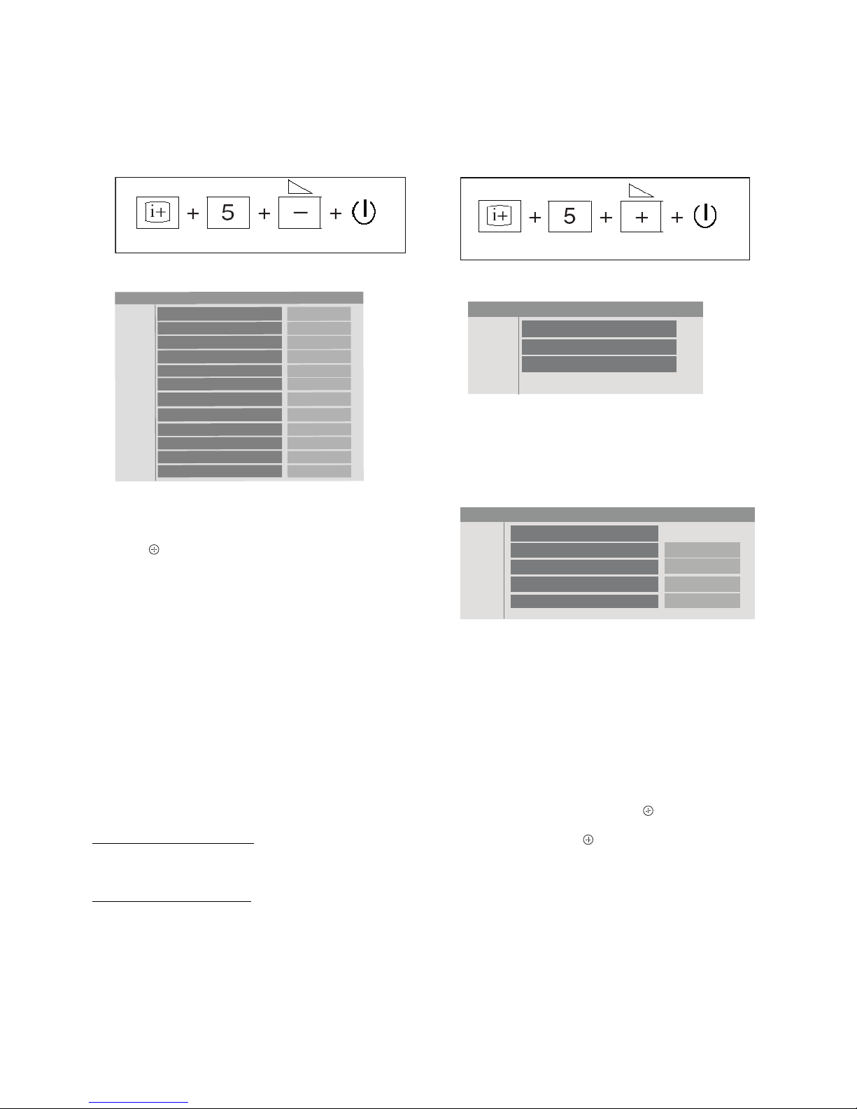
5-1. Accessing Diagnostic Menu
1. While TV set on standby, press the following sequence on
the remote commander (RM-GA011).
2. The following menu will appear on the screen:
3. To reset, select ‘RESET’ using remote commander and
press
.
4. To quit the diagnostic menu, turn off and on the TV set.
5-2. Aging
1. Aging setting: Set no signal and monitor as aging mode.
2. Aging condition:
Aging condition before white balance adjustment is as
follows:
Supply voltage : Rating
Time : 20 minutes or over
(AGING TIMER registor setting)
Ambient Temp : 22 ~ 28 degree
Brightness : Brightness is set by aging mode.
Input : Set no signal except digital and
analog RF (video/component/PC).
3. LED lightning pattern during aging:
In case the AGING TIMER > 0
Green (0.5s) --> Off (0.5s) --> Green (0.5s) --> Off (0.5s)
Note: Green (Power LED is ON / OFF)
In case the AGING TIMER = 0
Green (3s) -->Off (3s) --> Green (3s) --> Off (3s)
Note: Green (Power LED is ON / OFF)
Note: If set has been put on surface down, static electricity
causes brightness surface irregularity. If such happens, turn
the set over or place it in upright position for more than 30
seconds. Once surface irregularity is cleared, check the set.
On screen
display
Channel 5
Volume (-)
POWER
ERROR
DC_DET
DC_ALERT1
DC_ALERT2
DC_ALERT3
BACKLIGHT
INTERNAL TEMP ERROR
AUDIO ERROR
NVM ERROR
IIC ERROR
BALANCER ERROR
HDMI ERROR
0
0
0
0
0
0
0
0
0
0
0
RESET
0
Service Menu
Status
W/B
Service
On screen
display
Channel 5 Volume (+)
POWER
Service Menu
W/B
R_DRIVE
G_DRIVE
B_DRIVE
COLOR _ SAVE
0
0
0
OK
5-3. Accessing Service Menu
1. While TV set on standby, press the following sequence on
the remote commander (RM-GA011).
2. The following menu will appear on the screen:
3. View Menu Listing
Press the 'down' arrow button to choose white balance
(W/B) and then press 'right' arrow button to view W/B
adjustment items.
4. Select Menu Item
Press the 'up' or 'down' arrow button to select the item you
want to adjust.
5. Increase/Decrease Data Value
To increase the data value, press the 'right' arrow button
whereas to decrease, press the 'left' arrow button.
6. Save/Cancel Data Value
To save the data value changes, firstly press the 'down'
arrow button to select 'COLOR SAVE' then use 'right' arrow
button to select 'OK' and press the
button. To cancel the
data value changes, use 'down' arrow button to select
'Cancel' and press the
button.
SECTION 5
SERVICE ADJUSTMENTS
Figure 1
Figure 2
Figure 3
– 22 –
KLV-26,32,32/H/S,37 S400A
RM-GA011
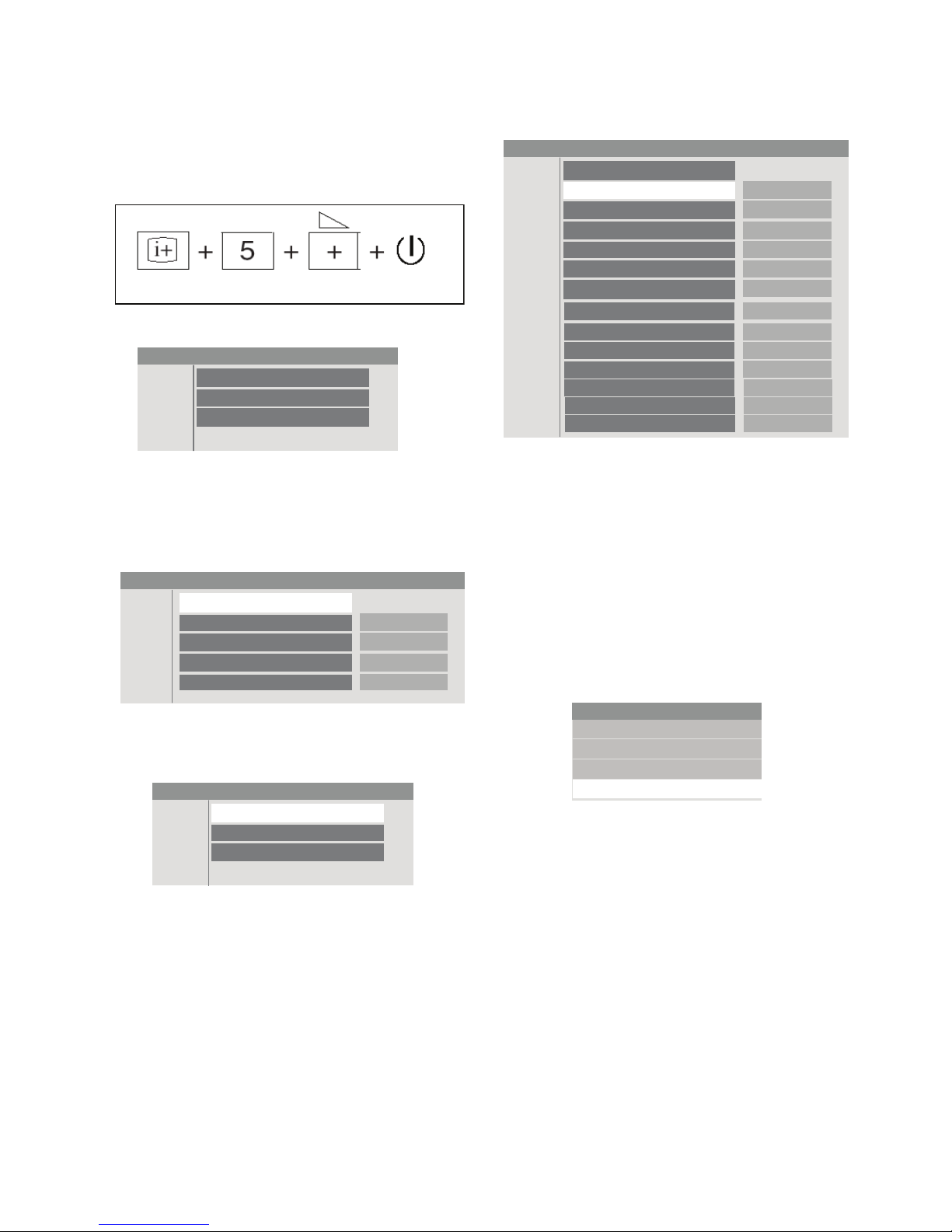
5-4. Resetting the User Menu - Factory Reset
Note: The TEST RESET option resets all the customer
adjustable data back to factory defaults.
1. While TV set on standby, press the following sequence on
the remote commander (RM-GA011).
2. The following menu will appear on the screen:
3. View Menu Listing
Press the 'down' arrow button to choose white balance
(W/B) and then press 'right' arrow button to view W/B
adjustment items.
4. Now return to Service Menu.
5. Press 'down' arrow button and select 'Service'. Then press
'right' arrow button to display 'Service' category items. The
below menu is displayed:
6. Press the 'Enter' button to select 'TEST RESET' option.
7. Press 'up' arrow button to select OK and 'Enter' button to
confirm.
5-5. White Balance Adjustment
Note: The white balance need to be adjusted when
BG1 board and Panel is replaced.
1. Put TV to Video 1 and step gray scale using signal
generator.
2. Press 'MENU' on the remote commander to display user
menu.
3. Select 'Setting' by pressing the 'down' arrow button.
4. While in 'Setting', press 'right' arrow button to display setting
options.
Service Menu
Service
TEST RESET
WHITE PATTERN
RED PATTERN
GREEN PATTERN
BLUE PATTERN
AUTOSET FACTORY
PRODUCTION
APC
OVER MODULATION
OPTIONS
OK
No
No
No
No
SHIBAURA
0
NORMAL
O
0
SERIAL NUMBER EDIT
ETI1 CLEAR
ETI2 CLEAR
0
Cancel
Cancel
MENU
Favourites
Programme List
External Inputs
Settings
Figure 4
Service Menu
W/B
R_DRIVE
G_DRIVE
B_DRIVE
COLOR_SAVE
0
0
0
OK
Figure 5
Service Menu
Status
W/B
Service
Figure 6
Figure 7
Figure 8
On screen
display
Channel 5 Volume (+) POWER
Service Menu
Status
W/B
Service

– 23 –
KLV-26,32,32/H/S,37 S400A
RM-GA011
SET-UP
56mv
20%
188mv
60%
451mv
10 STEP
GRAY SCALE
60 IRE LEVEL20 IRE LEVEL
8. Put the set in standby mode. (Power OFF).
9. Access the service menu.
10. The service menu displays.
11. Press the 'down' arrow button to choose white balance
(W/B) and then press 'right' arrow button to view W/B
adjustment items.
12. Using 10 step NTSC Gray scale with setup, adjust the white
balance of the 60% shade with R_Drive and B_Drive.
13. Using the same pattern, adjust the white balance 20% with
R_BKG and B_BKG.
14. 20 IRE and 60 IRE shades should have the same color.
5-6. Board & Panel Replacement
When replacing the BG1 board and Panel, make sure to readjust
the W/B.
While in Picture Menu:
5. Select 'Picture Mode' and press 'right' arrow button to display
picture mode options then select 'STANDARD' and press
button.
6. Next select 'Color Temperature' and press 'right' arrow
button to select the option 'COOL' and press
.
7. Now select 'Advanced Setting' and using the arrow keys,
set all the registers in the Advanced Setting menu OFF'.
Picture
Picture Mode
Reset
Backlight
Picture
Brightness
Colour
Hue
Colour Temperature
Sharpness
Noise Reduction
MPEG Noise Reduction
OK
5
Max
50
50
Cool
13
Medium
Advanced Settings
Standard
Picture
Picture Mode
Reset
Backlight
Picture
Brightness
Colour
Hue
Colour Temperature
Sharpness
Noise Reduction
MPEG Noise Reduction
OK
5
Max
50
50
Cool
13
Medium
Advanced Settings
Standard
Picture
Picture Mode
Reset
Backlight
Picture
Brightness
Colour
Hue
Colour Temperature
Sharpness
Noise Reduction
MPEG Noise Reduction
OK
5
Max
50
50
Cool
13
Medium
Advanced Settings
Standard
Service Menu
Status
W/B
Service
Service Menu
W/B
R_DRIVE
G_DRIVE
B_DRIVE
COLOR _SAVE
0
0
0
OK
Figure 9
Figure 10
Figure 11
Figure 12
Figure 13
– 24 –
KLV-26,32,32/H/S,37 S400A
RM-GA011
6-2. CIRCUIT BOARD LOCATION
KLV-26,32,32/H/S,37 S400A
Block Switch Panel
BG1 Board
GP Board
(KLV-26,32,32/H/S S400A)
Power Unit (G2D Board)
(KLV-37S400A)
HG4 Board
(KLV-26,32,32/H/S S400A)
HG4A Board
(KLV-37S400A)
SECTION 6
DIAGRAMS
6-1. BLOCK DIAGRAM
Due to complexity of the board, performing
component level field repairs are not recommended.
Complete board replacement is required if service is
necessary.
 Loading...