

Page 1
HISTORY INFORMATION FOR THE FOLLOWING MANUAL:
SERVICE MANUAL
Chassis Name : RB2TP
ORIGINAL MANUAL ISSUE D ATE: 3/2014
Segment Name : MC
Version Date Subject
1.0 3/2014 Original manual issue.
1.1 4/2014 Update P/N [page 13]
Update RMD Model Information
Serial Number Reset (India & RMD Country)
1.2 9/2014 Correct P/N [page 12]
LCD Digital Color TV
9-888-153-03
1
Page 2
MODEL LIST
MODEL COLOR COMMANDER DEST.
KLV-22P402B IN5 Black RM-GA025 INDIA
KLV-24P412B IN5 Black RM-GA025 INDIA
KLV-22P422B IN5 Black RM-GA025 INDIA
KLV-24P412B SP1 Black RM-GA025 RMD[Myanmar]
KLV-24P412B SP1 Black RM-GA025 RMD[Cambodia]
KLV-24P412B SP1 Black RM-GA025 RMD[Maldives]
KLV-24P412B SP1 Black RM-GA025 RMD[Nepal]
KLV-24P412B SP1 Black RM-GA025 RMD[Sri Lanka]
KLV-24P412B SP1 Black RM-GA025 RMD[Brunei]
KLV-24P412B SP1 Black RM-GA025 RMD[Mongolia]
KLV-24P412B SP1 Black RM-GA025 RMD[Papua N ew Guinea]
KLV-24P412B SP1 Black RM-GA025 RMD[Fiji]
KLV-24P412B SP1 Black RM-GA025 RMD[Vanuatu]
KLV-24P412B SP1 Black RM-GA025 RMD[Bangladesh]
KLV-24P412B SP1 Black RM-GA025 RMD[New Caledonia]
KLV-24P412B SP1 Black RM-GA025 RMD[French Polynesia]
MODEL COLOR COMMANDER DEST.
KLV-22P402B/24P412B/24P42 2B (IND/RMD)
2
Page 3

Table of content
Description Page
WARNINGS AND CAUTIONS………………………………..................….4
USE CAUTION WHEN HANDLING THE LCD PANEL……………….…5
SAFETY CHECK-OUT………………………………………………….…….6
SELF DIAGNOSIS FUNCTION…………………………….………………. 8
SERVICE POSITION…………………………………………………….…...9
SEC 1. DISASSEMBLY AND PARTS LIST……………………………….10
1-1. KLV-22P402B IN5………………………………………………..…11
1-1-1. BASE STAND………………………………………….............11
1-1-2. REAR COVER ……………………………………… ………..12
1-1-3. POWER BOARD, A BOARD AND SPEAKER..................13
1-1-4. LCD PANEL AND BEZEL……………………………..….…14
1-1-5. MISCELLANEOUS…………………………………………...15
1-2. KLV-24P412B IN5/ KLV-24P412B SP1………………………….16
1-2-1. BASE STAND…………………………………………………..16
1-2-2. REAR COVER..………………………………………………..17
1-2-3. POWER BOARD, A BOARD AND SPEAKER……………18
1-2-4. LCD PANEL AND BEZEL………………………………..….19
1-2-5. MISCELLANEOUS……………………………………………20
1-3. KLV-24P422B IN5………………………………………………….21
1-3-1. BASE STAND…………………………………………………..21
Description Page
1-5. How to disassemble front bezel
[KLV-22P402B IN5 /24P412B IN5 /24P422B IN5/24P412B SP1]…..27
1-6. How to disassemble Deco
[KLV-22P402B IN5/24P412B IN5 /24P422B IN5/24P412B SP1]… .28
1-7. How to disassemble LVDS cable
[KLV-22P402B IN5/KLV -24P412B IN5 /24P422B IN5 /24P412B SP1]...29
1-8. How to disassemble IR Board
[KLV-22P402B IN5/24P412B IN5 /24P422B IN5 /24P412B SP1]……..30
1-9. How to ass’y the LED lens [KLV-22P402B IN5 /24P412B IN5
/24P422B IN5 /24P412B SP1]…………………………..31
1-10. How to assemble the Himeron Countermeasure of panel
[KLV-22P402B IN5 /24P412B IN5 /24P422B IN5 /24P412B SP1]… 32
1-10-1. KLV-22P402B IN5…………………………………………..32
1-10-2. KLV-24P412B IN5 /24P422B IN5 /24P412B SP1……….34
SEC 2. ADJUSTMENT……………………………………………………. ..35
SEC 3. DIAGRAMS AND CHASSIS STRUCTURE……………………..37
3-1. BLOCK DIAGRAM…………………………………………………37
3-2. CONNECTOR DIAGRAM…………………………………………38
3-3. CIRCUIT BOARDS LOCATION…………………………………..39
3-4. Tape location…………………………………………………………40
APPENDIX-1 Trouble analysis flow………………………………………42
APPENDIX-2 Software data update………………………………………43
APPENDIX-3 Operation Time, Boot Count, Panel Operation Time…..45
APPENDIX-4 Reset and Edit Serial Number…………………………….46
1-3-2. REAR COVER …………………………………………………22
1-3-3. POWER BOARD, A BOARD AND SPEAKER……………23
1-3-4. LCD PANEL AND BEZEL………………………………..….24
1-3-5. MISCELLANEOUS……………………………………………25
1-4. How to disassemble rear cover
[KLV-22P402B IN5/24P412B IN5 /24P422B IN5 /24P412B SP1]…..26
KLV-22P402B/24P412B/24P42 2B (IND/RMD)
3
Page 4

WARNINGS AND CAUTIONS - ENGLISH
CAUTION
These servicing instructions are for use by qualified service personnel only.
To reduce the ri sk o f el ec tr ic s hoc k, d o not per for m any s er vic ing other than tha t c ont ai ned in t he o p er at ing ins tr ucti o ns unless you are qualified to do so.
WARNING!!
An isolation transformer should be used during any service to avoid possible shock hazard, because of live chassis.
The chassis of this receiver is directly connected to the ac power line.
CARRYING THE TV
Be sure to follow these guidelines to protect your property and avoid causing serious injury.
• Carry the TV with an adequate number of people; larger size TVs require two or more people.
• Correct hand placement while carrying the TV is very important for safety and to avoid damages.
SAFETY-RELATED COMPONENT WARNING!!
Components identified by shading and ! mark on the schematic diagrams, exploded views, and in the parts list are critical for safe operation. Replace these components with Sony
parts whose part numbers appear as shown in this manual or in supplements published by Sony. Circuit adjustments that are critical for safe operation are identified in this manual.
Follow these procedures whenever critical co mponents are replaced or improper operation is suspected.
KLV-22P402B/24P412B/24P42 2B (IND/RMD)
4
Page 5
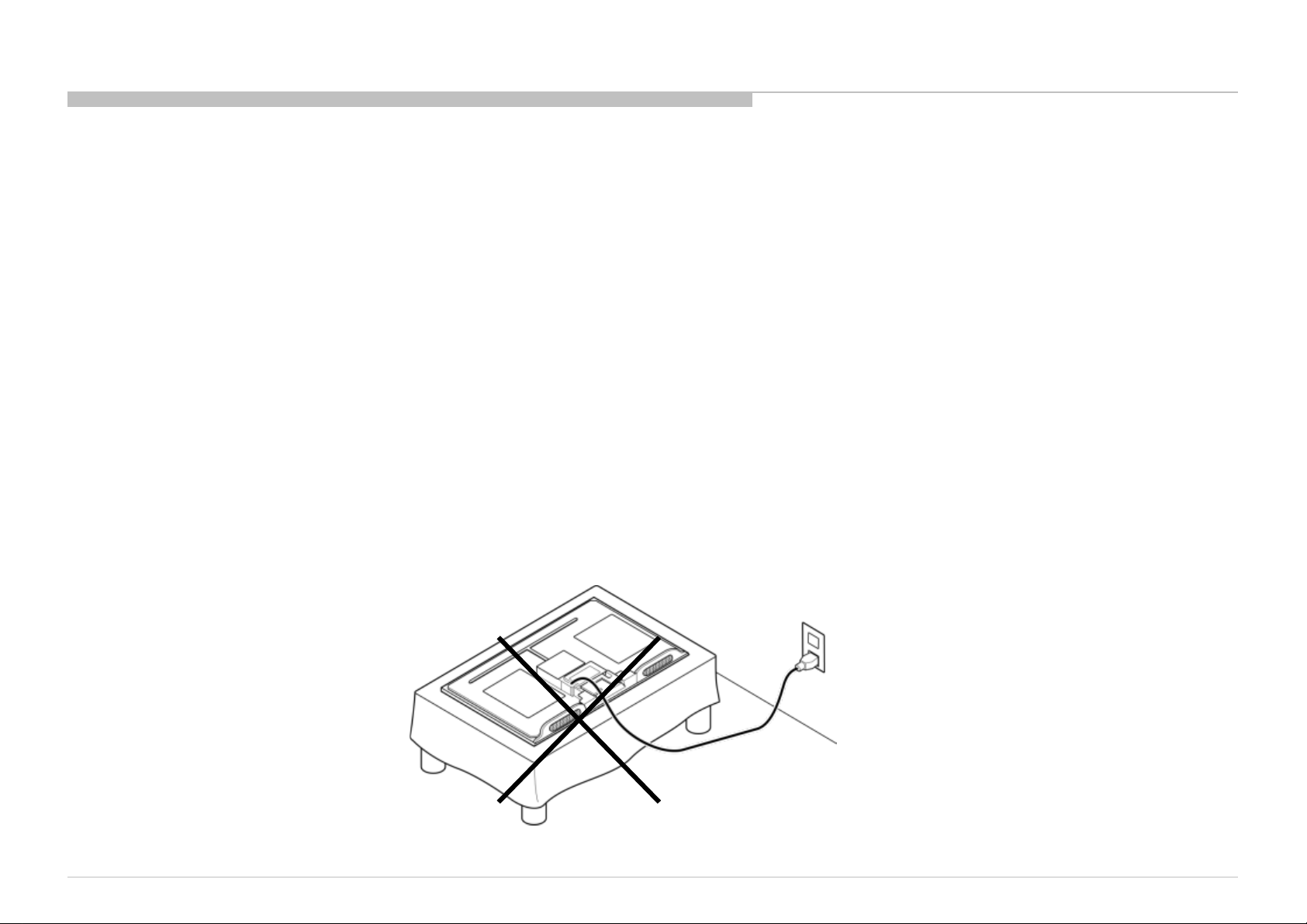
USE CAUTION WHEN HANDLING THE L CD PANEL
When repair ing t he LCD p a nel , b e sure you ar e gro und ed b y using a wrist b and .
When repair ing t he LCD p a nel on the wall , the LCD panel must be secured us ing the 4 mounting holes on the r ea r c o ver .
1) Do not press on the panel or frame edge to avoid the risk of electric shock.
2) Do not scratch or press on the panel with any sharp objects.
3) Do not leave the module in high temperatur es or in areas of high humidity fo r an extend ed p eri od of time.
4) Do not expose the LCD panel to direct sunlight.
5) Avoid contact with water. It may cause a short circuit within the module.
6) Always clean the LCD panel with a soft cloth material.
7) Use care when handling the wires or connectors of the inverter circuit. Damaging the wires may cause a short.
8) Protect the panel from ESD to avoid damaging the electronic circuit (C-MOS).
9)It is recommended not to exceed 1 hour of Power-On nor Burn-in per iod with LCD panel face d own conditio n, in repair activity.
10)Disconnect the AC power when replacing the parts.(FFC cable etc.).
WARNINGS AND CAUTIONS
KLV-22P402B/24P412B/24P42 2B (IND/RMD)
5
Page 6

SAFETY CHECK-OUT
After correcting the original service problem, perform the following safety checks before releasing the set to the customer:
1. Check the area of your repair for unsoldered or poorly soldered connections. Check the entire board surface for solder splashes and bridges.
2. Check the interboard wiring to ensure that no wires are “pinched” o r touching high-wattage resistors.
3. Check that all control knobs, shields, covers, ground straps, and mounting hardware have been replaced. Be absolutely certain that you have replaced all the insulators.
4. Look for unauthorize d replacement parts, particularly transistors, th a t were installed during a p revious repair. Point them out to the customer and recommend their replac ement.
5. Look for parts which, though functi oni n g, show obvio us s igns o f d ete r io ra ti on. P o int them out to the cust omer a nd re co mmend their replacement.
6. Check the line cords for cracks and abrasion. Recommend the replacement of any such line cord to the customer.
7. Check the antenna terminals, metal trim, “metallized” knobs, screws, and all other exposed metal parts for AC leakage. Check leakage as described below.
8. For safety reasons, repairing the Power board and/or Inverter board is prohibited.
KLV-22P402B/24P412B/24P42 2B (IND/RMD)
6
Page 7
Leakage Test
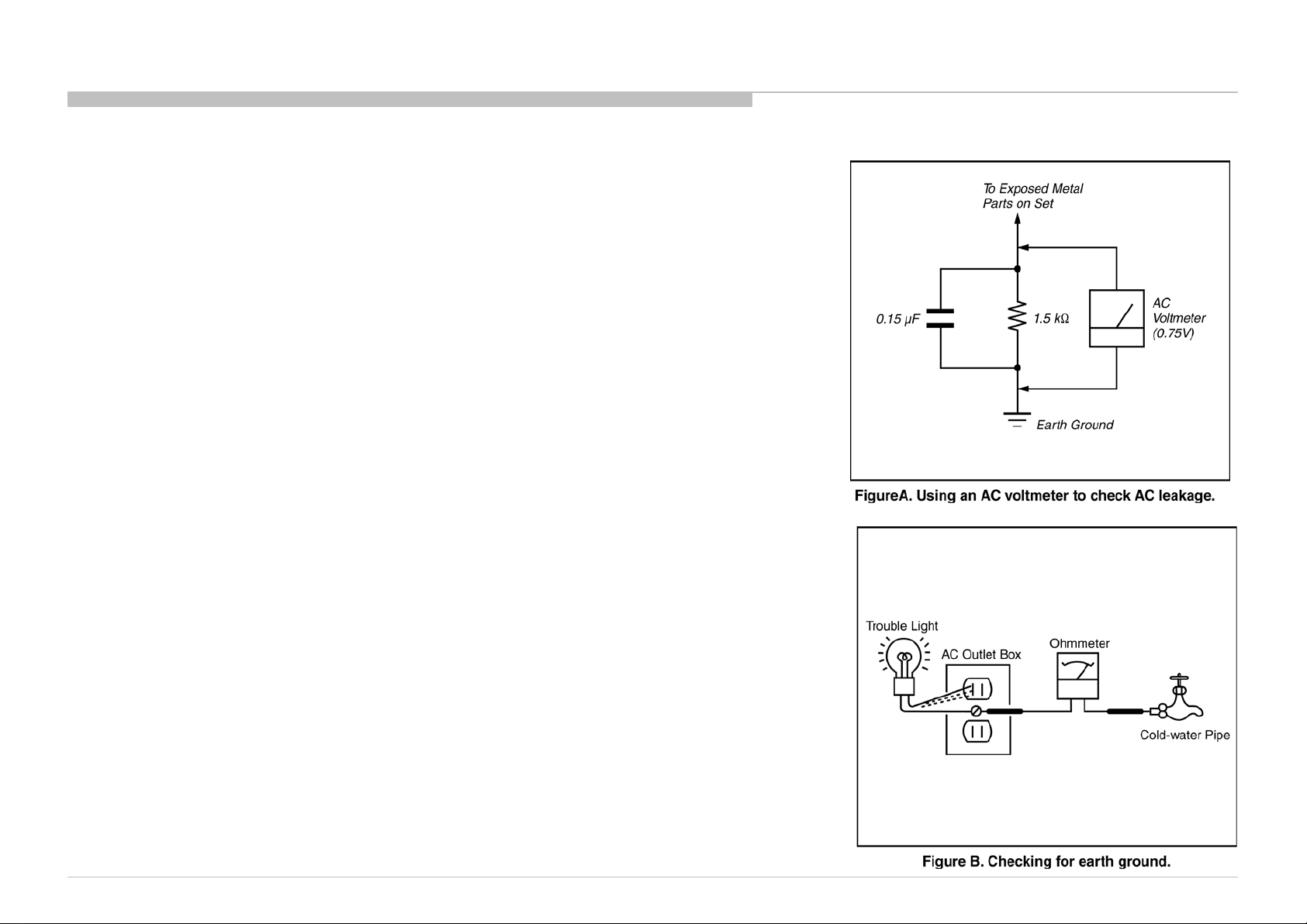
The AC leakage from any exposed metal part to earth ground and from all exposed m etal parts to any exposed
metal part having a return to chassis, must not exceed 0.5 mA (500 microamperes).
Leakage current can be measured by any one of three methods.
1. A commercial leak ag e tester, such as the Simpson 229 or RCA WT-540A. Follow the manufacturers’
instructions to use these instructions.
2. A battery-operated AC milliampmeter. The Data Precision 245 digital multim eter is suitable for this job.
3. Measuring the v oltage d rop across a resistor by means of a VOM or battery-operated AC voltmeter. The
“limit” indication is 0.75 V, so analog meters must have an accurate low voltage scale.
The Simpson’s 250 and Sanwa SH-63TRD are examples o f passiv e VO Ms that are suitabl e. Nearly all
battery-operated dig ital multimeters that have a 2 VAC range are suitable (see Figure A).
How to Find a Good Earth Ground
A cold-water pipe is a guaranteed earth ground; the cover-plate retaining screw on most AC outlet boxes is also
at earth ground.
If the retaining screw is to be used as y our earth g round , v erify that it is at ground by measuring the resistance
between it and a cold-water pipe with an ohmmeter. The reading should be zero ohms.
If a cold-water pipe is not accessible, connect a 60- to 100-watt trouble- light (not a neon lamp) between the hot
side of the receptacle and the retaining screw. Try both slots, if necessary, to locate the hot side on the line; the
lamp should light at normal brilliance if the screw is at ground potential (see Figure B).
SAFETY CHECK-OUT
KLV-22P402B/24P412B/24P42 2B (IND/RMD)
7
Page 8

SELF DIAGNOSIS FUNCTI ON
This model doesn’t support Self Diagnosis Function.
KLV-22P402B/24P412B/24P42 2B (IND/RMD)
8
Page 9
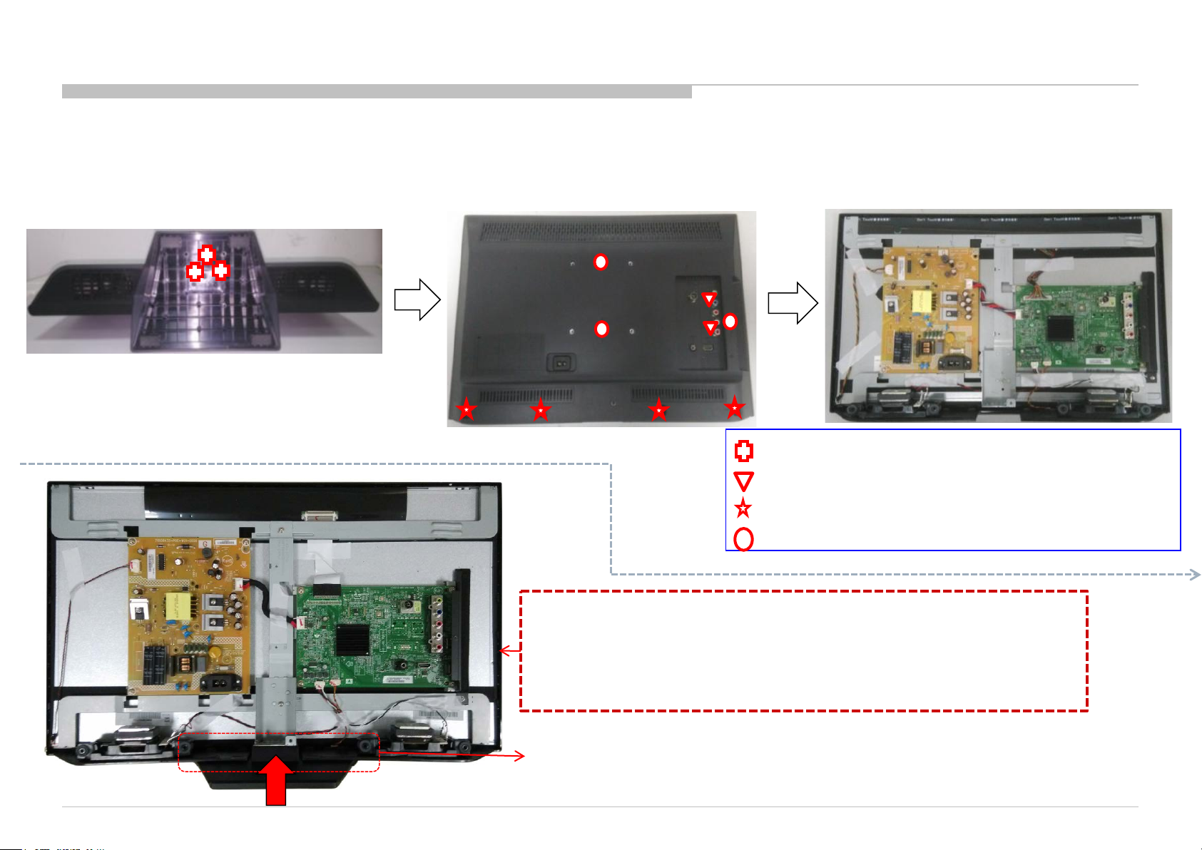
SERVICE POSITION
As for this model, the bottom of rear cover is installed between the stand assy and the panel.
Therefore according to the following procedure when performing adjustment and operation check after the part replacement.
<22/24inch>
1. Remove all screws on the Stand
to main unit (three screws)
2. Remove all screws on the Rear Cover to
Bezel & Main Board & Bracket (nine screws)
3. Afte r removing rear cover , lie down the main unit
to a surface for foll o wing test/repair.
4-537-025-01 SCREW, +PSW M4X16
7-685-660-79 SCREW +BVTP T3X8 TYPE2 IT-3
7-685-662-79 SCREW +BVTP 4X14 TYPE2 IT-3
2-580-592-01 SCREW, +PSW M3X8
KLV-22P402B/24P412B/24P42 2B (IND/RMD)
Attention: This photo is based on Sony criteria for appearing standing the
main unit after removing back cover and assembling the stand. But
considerin g m ech a n ical desig n of T2 models and norm al service p rocess, it
is not recommended to keep main unit standing by this status for
repairing / t est ing at repair c en ter. Please pay attention for avoiding
possible scra t ch / d ef orm ation occurred.
Note: Remove rear cover, then assemble the stand to main unit. This
will cause the stand with main unit fit closely, scratch or deformation
may occurred easily on the stand or bezel deco.
9
Page 10
SEC 1. DISASSEMBLY AND PARTS LIST
• Items with no part number and no description are not stocked because they are seldom required for roution service.
• The construction parts of an assembled part are indicated with a collation number in the remark colum.
• Items marked " * " are not stocked since they are seldom required for routine service. Some delay should be anticipated when ordering these items.
KLV-22P402B/24P412B/24P42 2B (IND/RMD)
10
Page 11
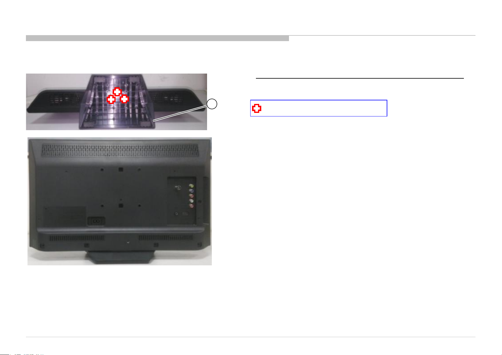
1-1. KLV-22P402B IN5
REF. No . PART No. DESCRIPTION MARK
1 4-534-466-01 BA SE ST AND
1-1-1. BASE STAND
DISASSEMBLY AND PARTS LIST
1
4-537-025-01 SCREW, +PSW M4X16
KLV-22P402B/24P412B/24P42 2B (IND/RMD)
11
Page 12
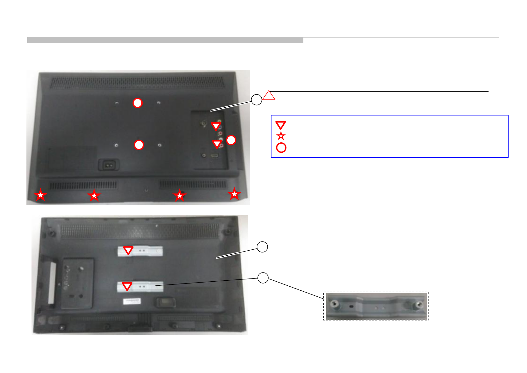
REF. No . PART No . DESCRIPTION MARK
2 4-534-469-01 REAR CO VER 22 (T2)
3
4-534-478-01 BRACKET, VESA (T2)
1-1. KLV-22P402B IN5
1-1-2. REAR COVER
DISASSEMBLY AND PARTS LIST
2
2
7-685-660-79 SCREW +BVTP T3X8 TYPE2 IT-3
7-685-662-79 SCREW +BVTP 4X14 TYPE2 IT-3
2-580-592-01 SCREW, +PSW M3X8
2
3
KLV-22P402B/24P412B/24P42 2B (IND/RMD)
12
Page 13
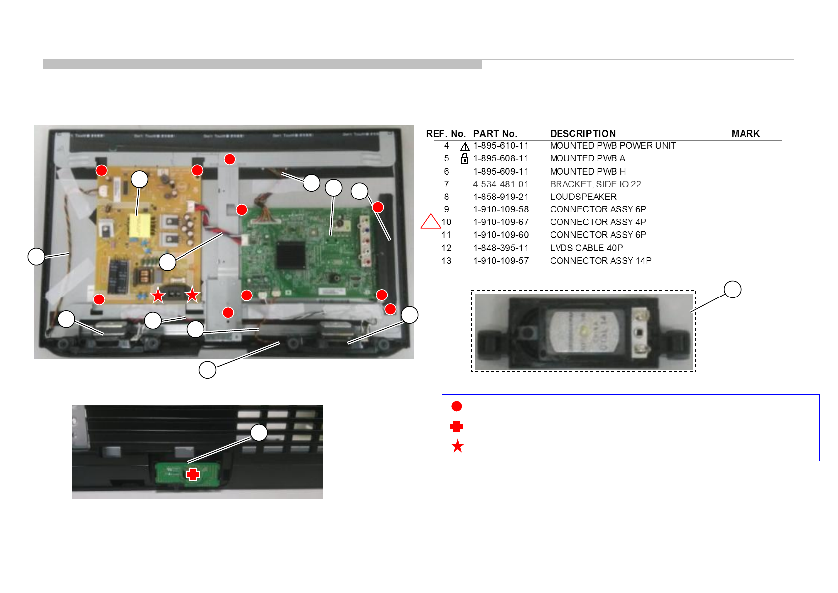
1-1. KLV-22P402B IN5
1-1-3. POWER BOARD, A BOARD AND SPEAKER
DISASSEMBLY AND PARTS LIST
11
4
12
5
7
1
13
8
8
10
9
6
8
4-679-053-01 SCREW +PS3X6
6
2-580-628-01 SCREW +BVTP S3X6 TYPE2
2-580-592-01 SCREW +PSW M3X8
KLV-22P402B/24P412B/24P42 2B (IND/RMD)
13
Page 14
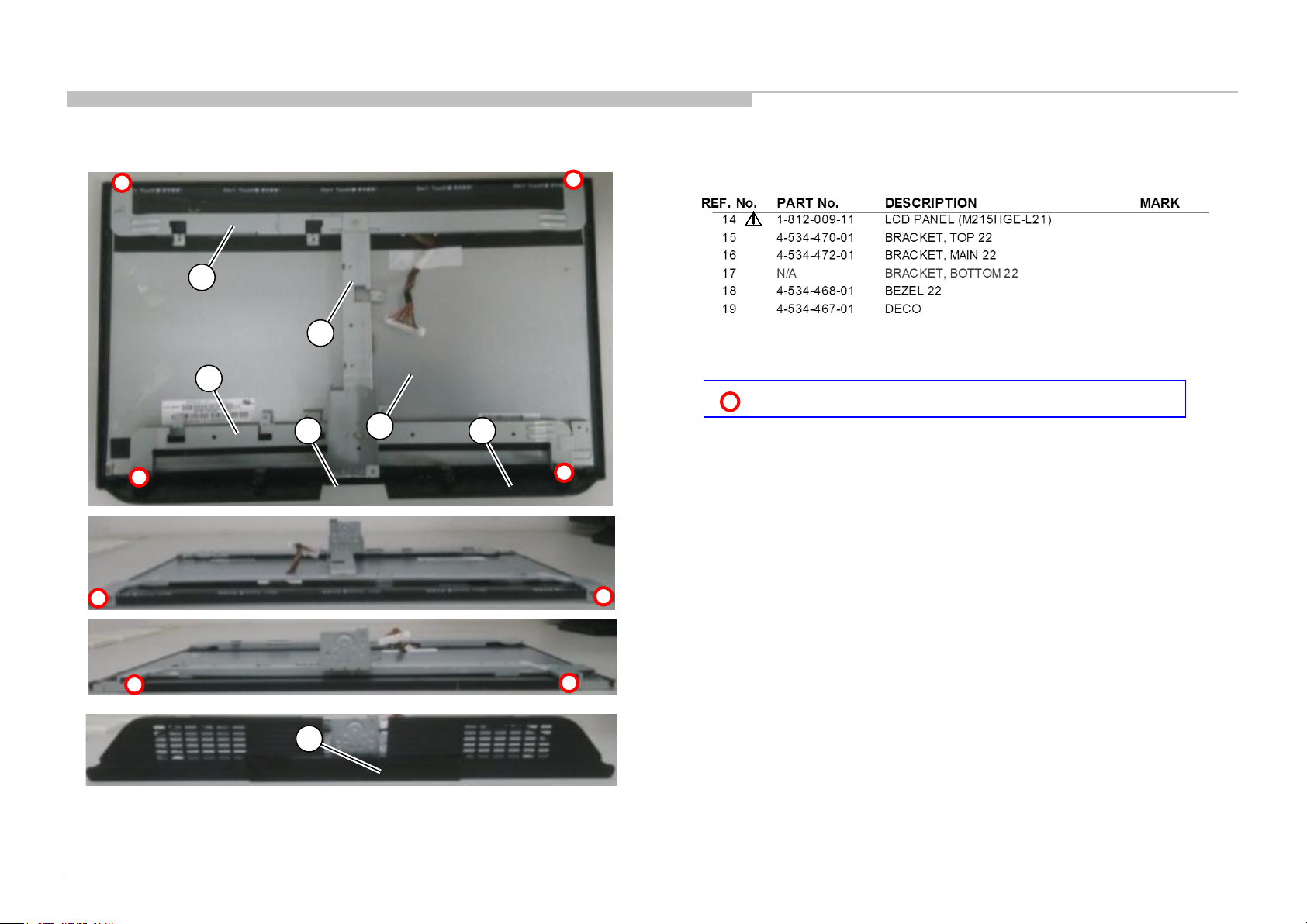
1-1. KLV-22P402B IN5
1-1-4. LCD PANEL AND BEZEL
15
16
17
14
DISASSEMBLY AND PARTS LIST
7-682-247-09 +K 3X6 SCREW +K 3X6
18 19
19
KLV-22P402B/24P412B/24P42 2B (IND/RMD)
14
Page 15
1-1. KLV-22P402B IN5
1-1-5. MISCELLANEOUS
DISASSEMBLY AND PARTS LIST
KLV-22P402B/24P412B/24P42 2B (IND/RMD)
15
Page 16
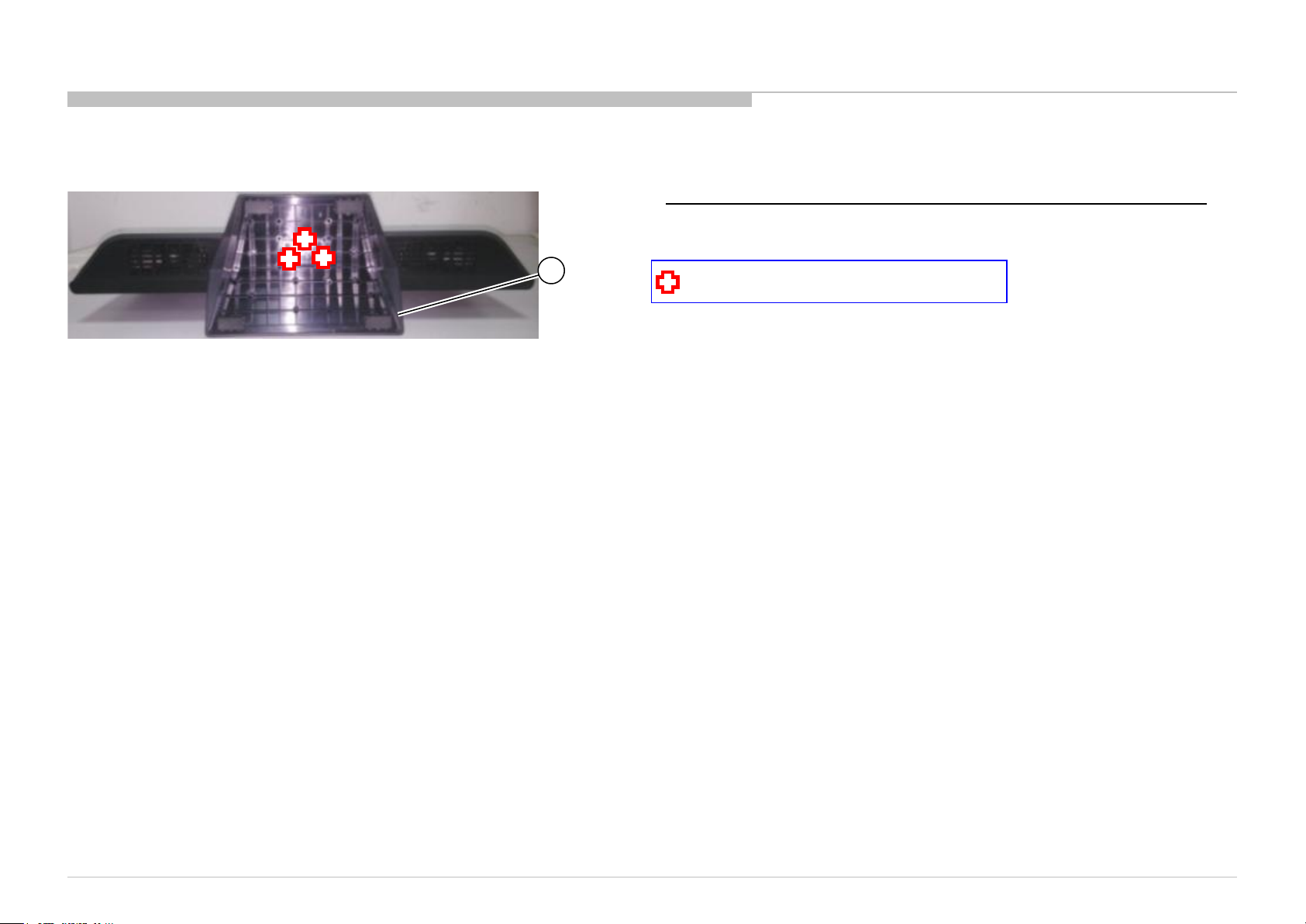
1-2. KLV-24P412B IN5 /24P412B SP1
REF. No . PART No. DESCRIPTION MARK
1 4-534-466-01 BA SE ST AND
1-2-1. BASE STAND
DISASSEMBLY AND PARTS LIST
1
4-537-025-01 SCREW, +PSW M4X16
KLV-22P402B/24P412B/24P42 2B (IND/RMD)
16
Page 17
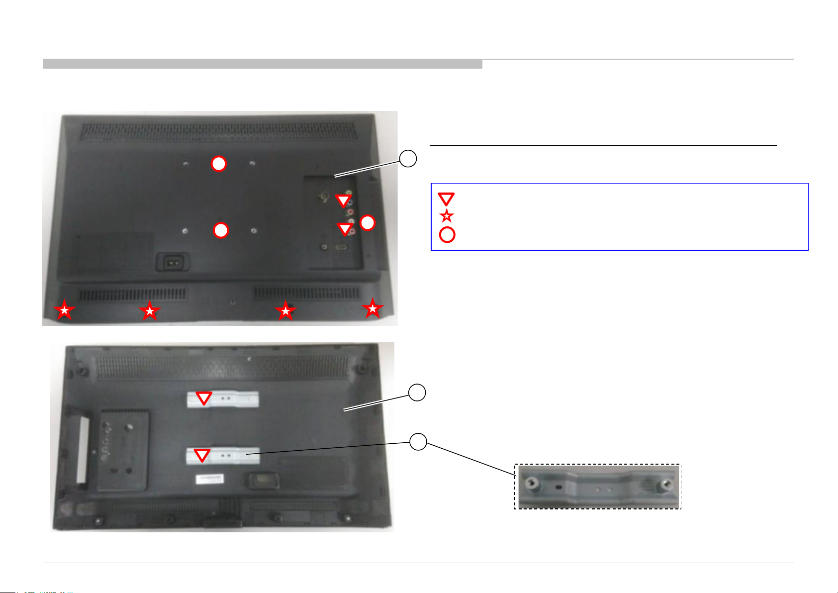
REF. No . PART No . DESCRIPTION MARK
2 4-534-482-01 REAR CO VER 24
3
4-534-478-01 BRACKET, VESA (T2)
1-2. KLV-24P412B IN5 /24P412B SP1
1-2-2. REAR COVER
DISASSEMBLY AND PARTS LIST
2
7-685-660-79 SCREW +BVTP T3X8 TYPE2 IT-3
7-685-662-79 SCREW +BVTP 4X14 TYPE2 IT-3
2-580-592-01 SCREW, +PSW M3X8
2
3
KLV-22P402B/24P412B/24P42 2B (IND/RMD)
17
Page 18
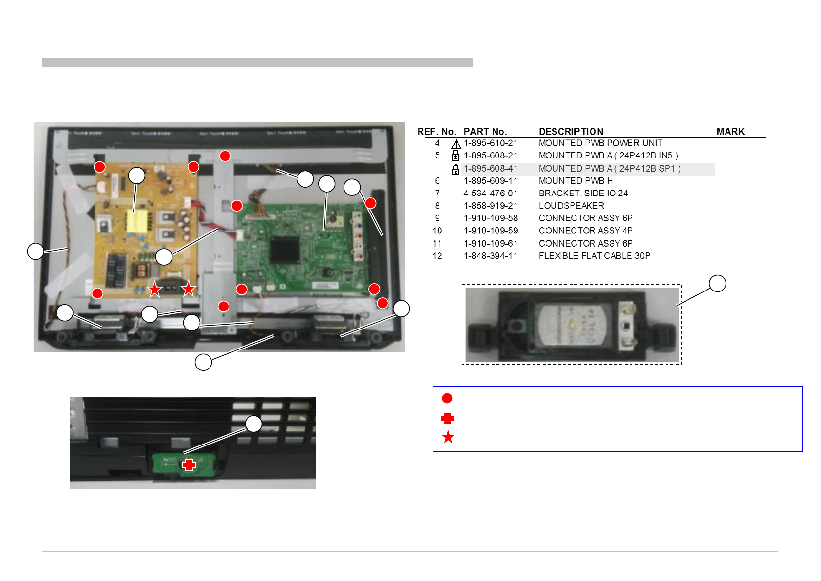
1-2. KLV-24P412B IN5 /24P412B SP1
1-2-3. POWER BOARD, A BOARD AND SPE AK E R
DISASSEMBLY AND PARTS LIST
11
4
13
8
10
9
6
12
5
7
8
8
4-679-053-01 SCREW,+PS3X6
6
2-580-628-01 SCREW, +BVTP S3X6 TYPE2
2-580-592-01 SCREW +PSW M3X8
KLV-22P402B/24P412B/24P42 2B (IND/RMD)
18
Page 19
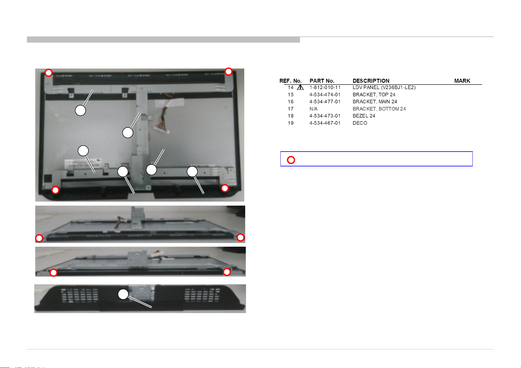
1-2. KLV-24P412B IN5 /24P412B SP1
1-2-4. LCD PANEL AND BEZEL
15
16
17
14
18 19
DISASSEMBLY AND PARTS LIST
7-682-247-09 +K 3X6 SCREW +K 3X6
19
KLV-22P402B/24P412B/24P42 2B (IND/RMD)
19
Page 20
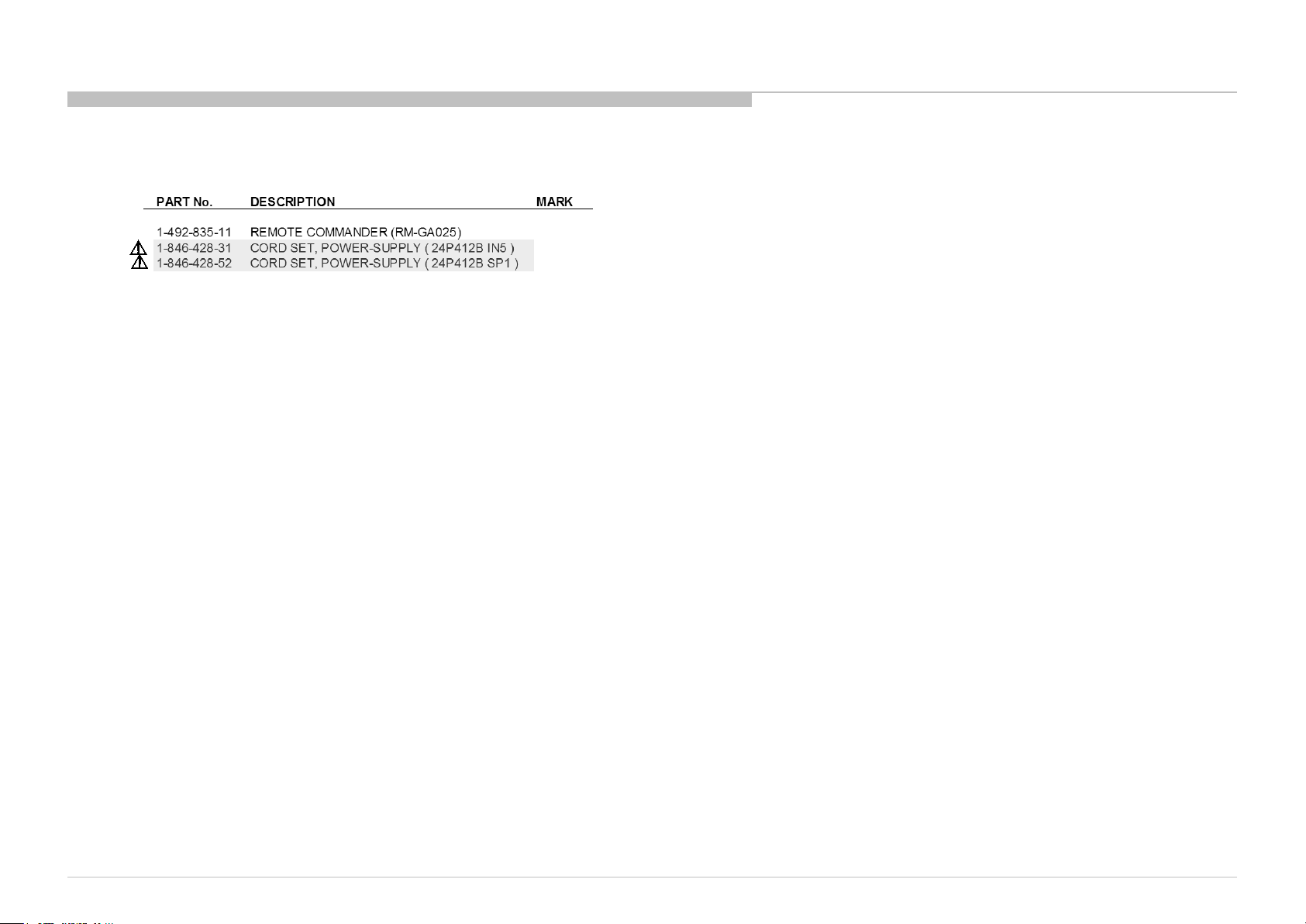
1-2. KLV-24P412B IN5 /24P412B SP1
1-2-5. MISCELLANEOUS
DISASSEMBLY AND PARTS LIST
KLV-22P402B/24P412B/24P42 2B (IND/RMD)
20
Page 21
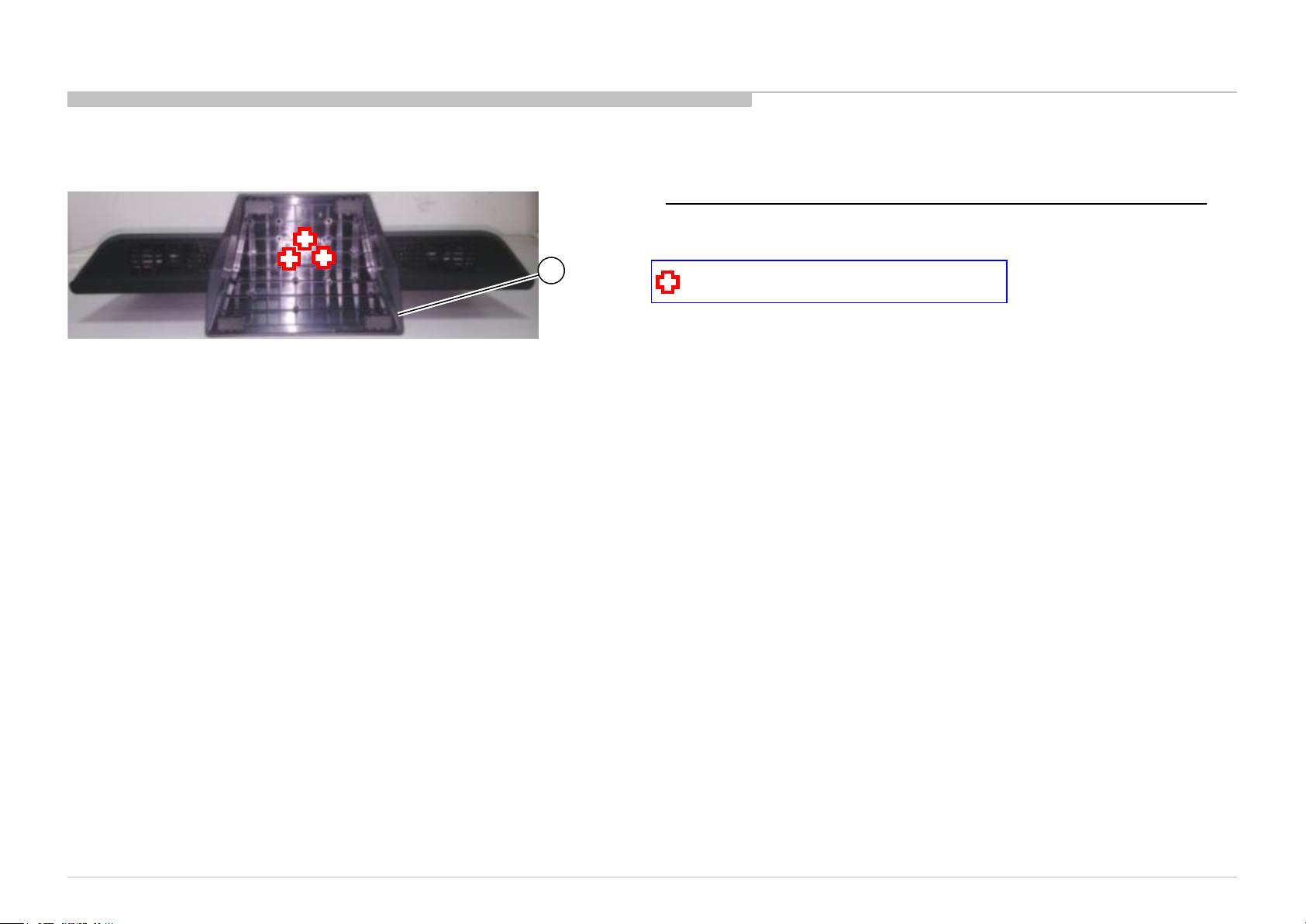
1-3. KLV-24P422B IN5
REF. No . PART No. DESCRIPTION MARK
1 4-534-466-01 BA SE ST AND
1-3-1. BASE STAND
DISASSEMBLY AND PARTS LIST
1
4-537-025-01 SCREW, +PSW M4X16
KLV-22P402B/24P412B/24P42 2B (IND/RMD)
21
Page 22
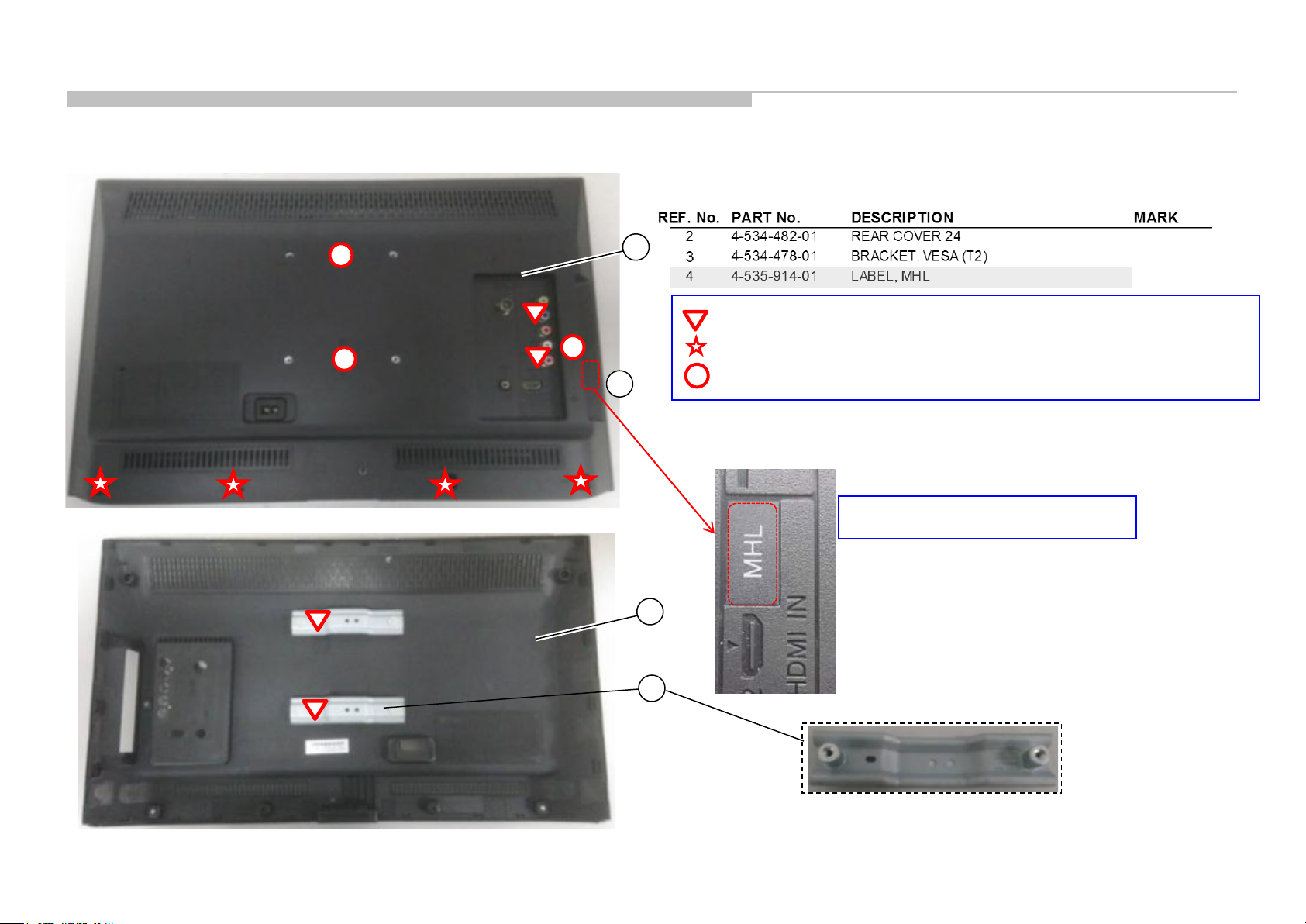
1-3. KLV-24P422B IN5
1-3-2. REAR COVER
DISASSEMBLY AND PARTS LIST
2
7-685-660-79 SCREW +BVTP T3X8 TYPE2 IT-3
7-685-662-79 SCREW +BVTP 4X14 TYPE2 IT-3
4
2-580-592-01 SCREW, +PSW M3X8
MHL label for KLV-24P422B
2
3
KLV-22P402B/24P412B/24P42 2B (IND/RMD)
22
Page 23
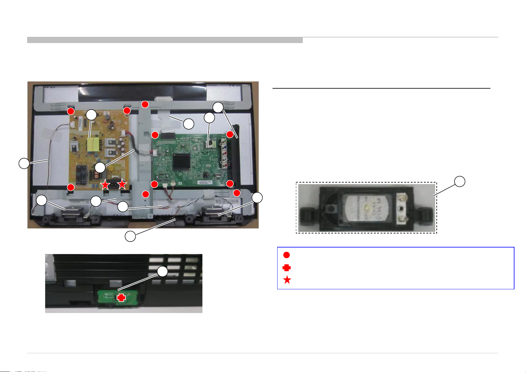
REF. No . PART No . DESCRIPTION MARK
4 1-895-610-21 MOUNTE D P WB P OWE R UNIT
5 1-895-608-31 MOUNTED PWB A
6 1-895-609-11 MOUNTED PWB H
7 4-534-476-01 BRA CKET, SI DE IO 24
8 1-858-919-21 LOUDSPEAKER
9 1-910-109-58 CO NNE CTO R ASSY 6P
10 1-910-109-59 CONNECTOR ASSY 4P
11 1-910-109-61 CONNECTOR ASSY 6P
12 1-848-394-11 FLEXIBLE FLAT CABLE 30P
13 1-910-109-57 CONNECTOR ASSY 14P
1-3. KLV-24P422B IN5
1-3-3. POWER BOARD, A BOARD AND SPE AK E R
4
DISASSEMBLY AND PARTS LIST
7
5
12
11
8
13
10
9
6
6
KLV-22P402B/24P412B/24P42 2B (IND/RMD)
8
8
4-679-053-01 SCREW,+PS3X6
2-580-628-01 SCREW, +BVTP S3X6 TYPE2
2-580-592-01 SCREW +PSW M3X8
23
Page 24
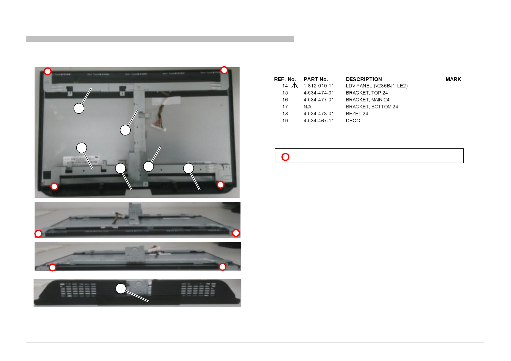
1-3. KLV-24P422B IN5
1-3-4. LCD PANEL AND BEZEL
15
16
17
14
DISASSEMBLY AND PARTS LIST
7-682-247-09 +K 3X6 SCREW +K 3X6
18 19
19
KLV-22P402B/24P412B/24P42 2B (IND/RMD)
24
Page 25
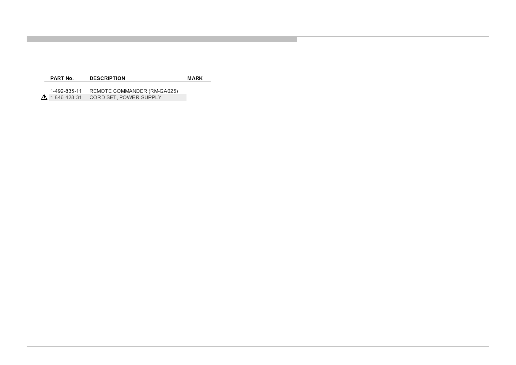
1-3. KLV-24P422B IN5
1-3-5. MISCELLANEOUS
DISASSEMBLY AND PARTS LIST
KLV-22P402B/24P412B/24P42 2B (IND/RMD)
25
Page 26
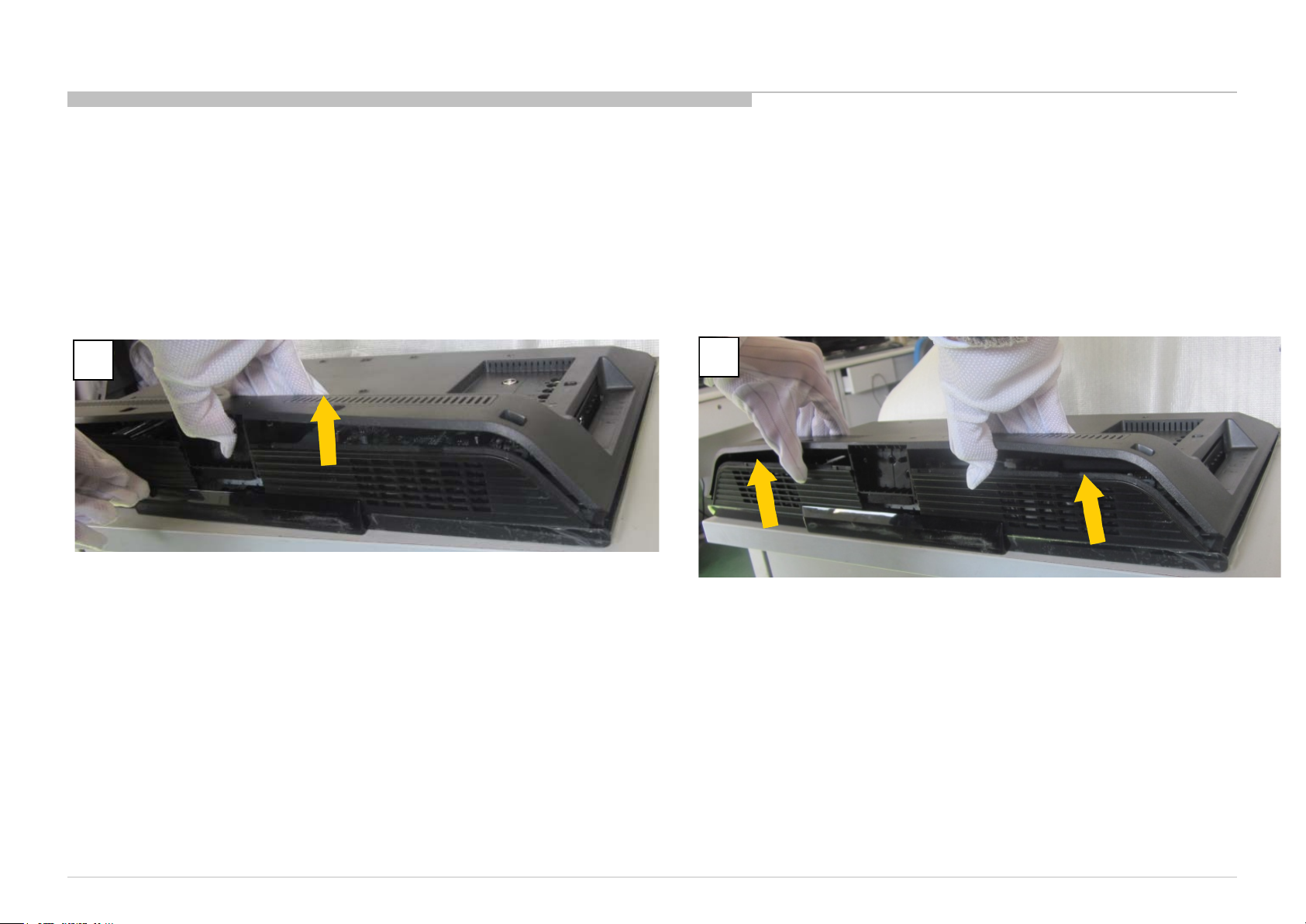
1-4. How to disassemble rear cover [KLV-22P402B IN5/24P412B IN5/24P422B IN5/24P412B SP1]
PROCEDURE TO REMOVAL OF REAR COVER
1. Remove all screws on Rear Cover and AC Cover.
2. Open Rear Cover in order as below.
1
Hold the panel from the middle of bezel, and lift rear cov er
in the direction of the arrow.
2
Hold the panel from the middle of bezel, and lift rear cov er
in the direction of the arrow.
KLV-22P402B/24P412B/24P42 2B (IND/RMD)
26
Page 27
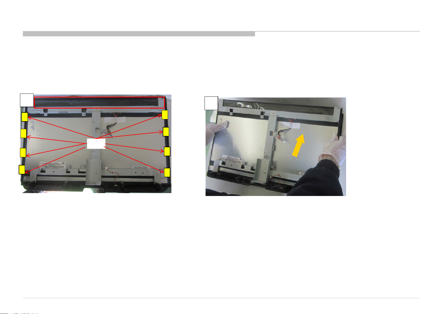
1-5. How to disassemble front bezel [KLV-22P402B IN5 /24P412B IN5 /24P422B IN5 /24P412B SP1]
PROCEDURE TO REMOVAL OF FRONT BEZEL
1. Remove all screws on Rear Cover and AC Cover.
2. Open Rear Cover in order as below.
1
hook
Lift up top of panel , then release the of panel from hook
of panel
2
Then remove panel in the direction of the arrow
KLV-22P402B/24P412B/24P42 2B (IND/RMD)
27
Page 28
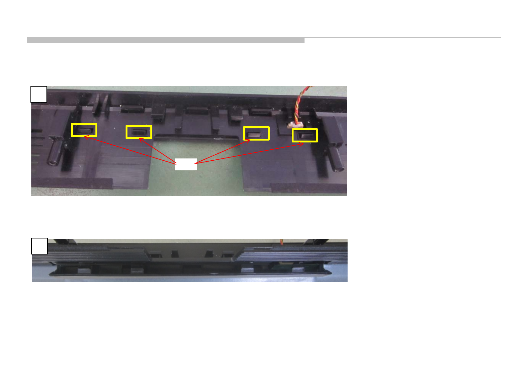
1-6. How to disassemble Deco [KLV-22P402B IN5/24P412B IN5/24P422B IN5/24P412B SP1]
PROCEDURE TO REMOVAL OF DECO
1
hook
Release deco from hook of bezel
2
Remove deco from bezel
KLV-22P402B/24P412B/24P42 2B (IND/RMD)
28
Page 29
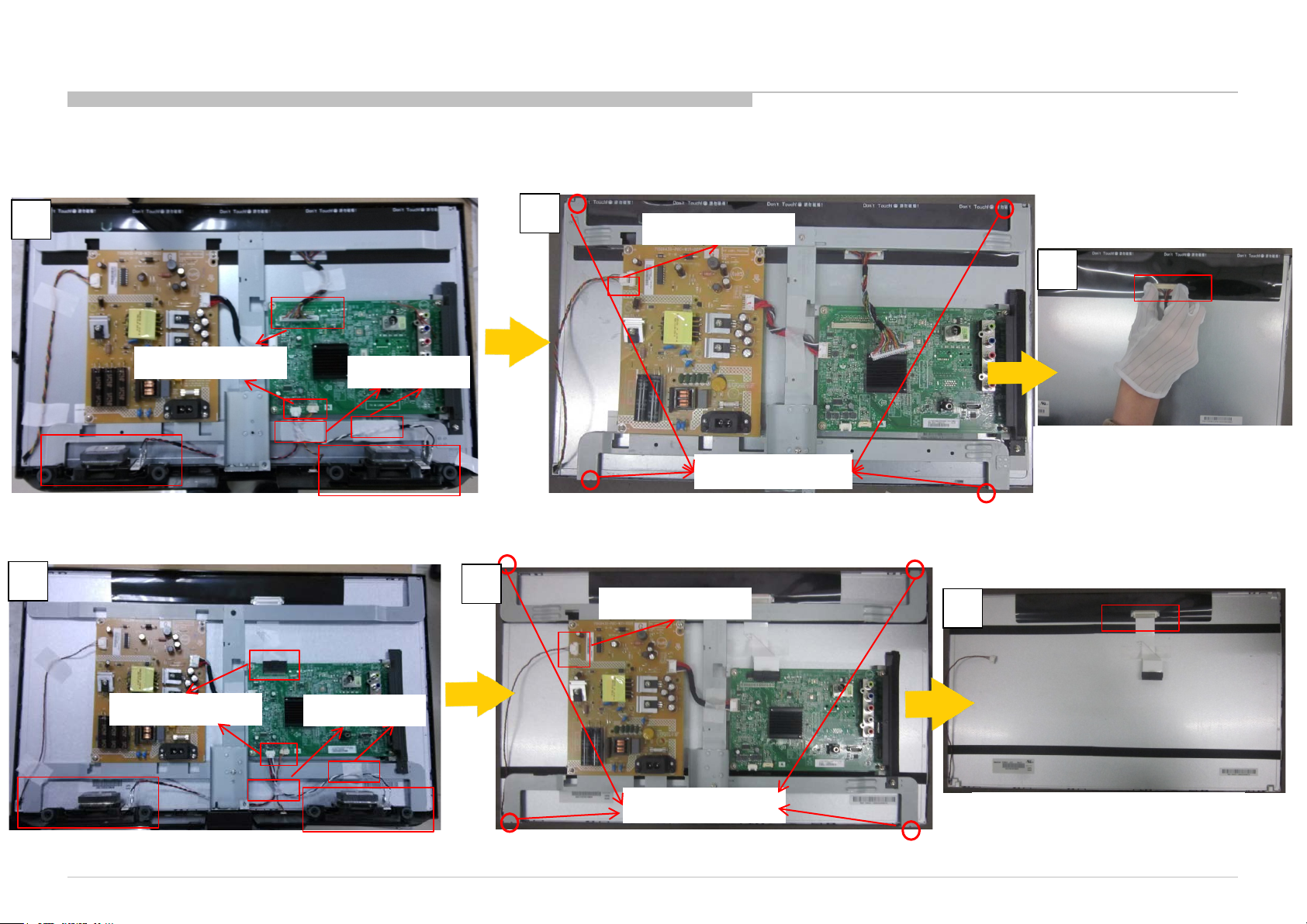
1-7. How to disassemble LVDS cable [KLV-22P402B IN5/KLV-24P412B IN5/24P422B IN5/24P412B SP1]
1-7-1. PROCEDURE OF REMOVING LVDS CABLE ON KLV-22P402B IN5
1
Remove the PIN
Remove tape
2
Remove the PIN
Remove the screws
Remove speaker , remove front bezel
Remove screws, remove metal bracket and boards ass’y. The metal bracket
and boards ass'y is a whole, no need to disassembly .
1-7-2. PROCEDURE OF REMOVING LVDS CABLE ON KLV-24P412B IN5/24P422B IN5
1
2
Remove the PIN
3
Press the 2 sides of LVDS, then pull
in the direction of the arrow
3
Remove the PIN
Remove speaker , remove front bezel
KLV-22P402B/24P412B/24P42 2B (IND/RMD)
Remove tape
Remove the screws
Remove screws, remove metal bracket and boards ass’y. The metal bracket
and boards ass'y is a whole, no need to disassembly .
Press the 2 sides of LVDS, then pull
in the direction of the arrow
29
Page 30
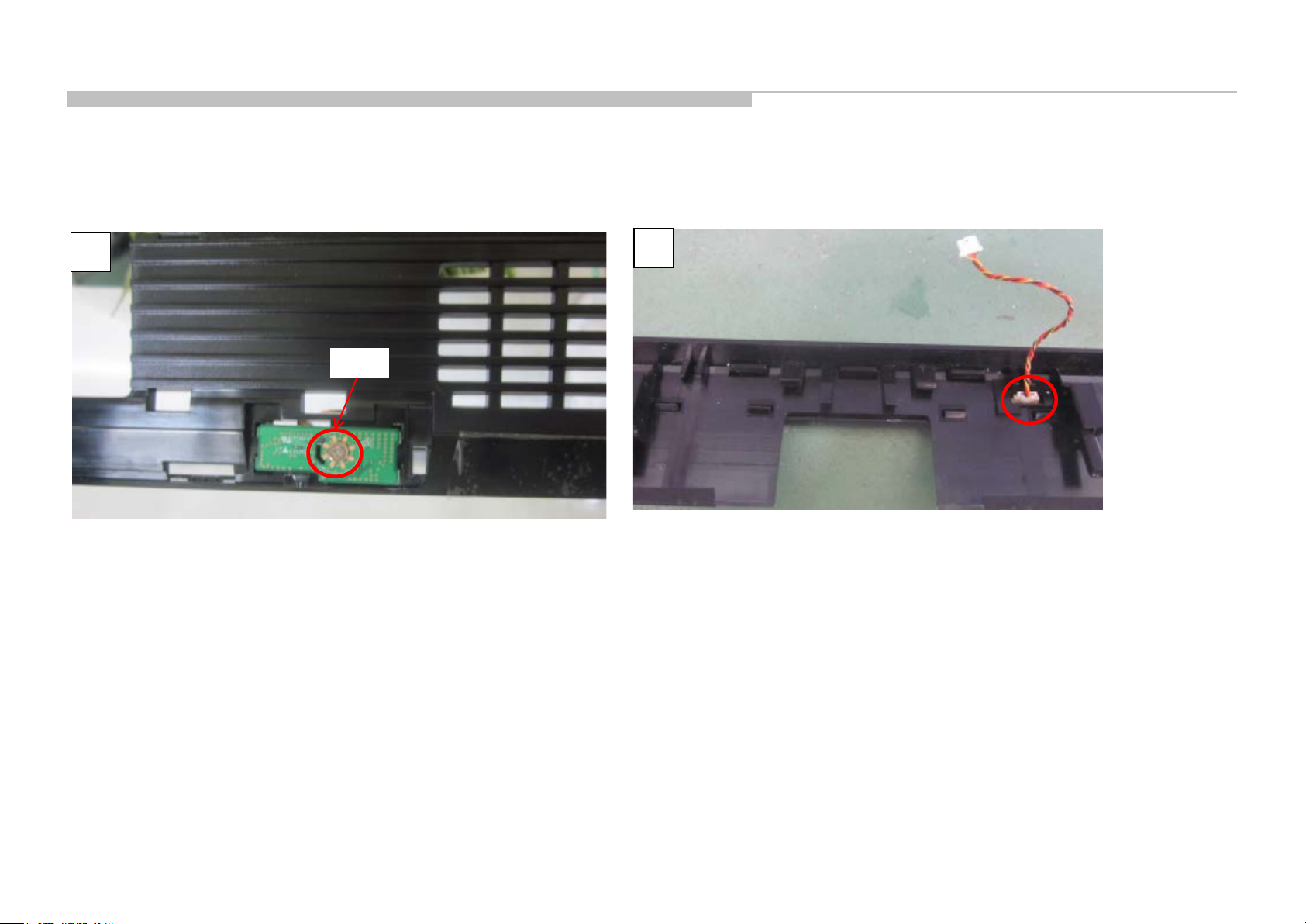
1-8. How to disassemble IR Board [KLV-22P402B IN5 /24P412B IN5/24P422B IN5 /24P412B SP1]
PROCEDURE TO REMOVAL OF IR Board
1
Disassemble deco
Then disassemble the screw
2
screw
Remove the IR cable
KLV-22P402B/24P412B/24P42 2B (IND/RMD)
30
Page 31
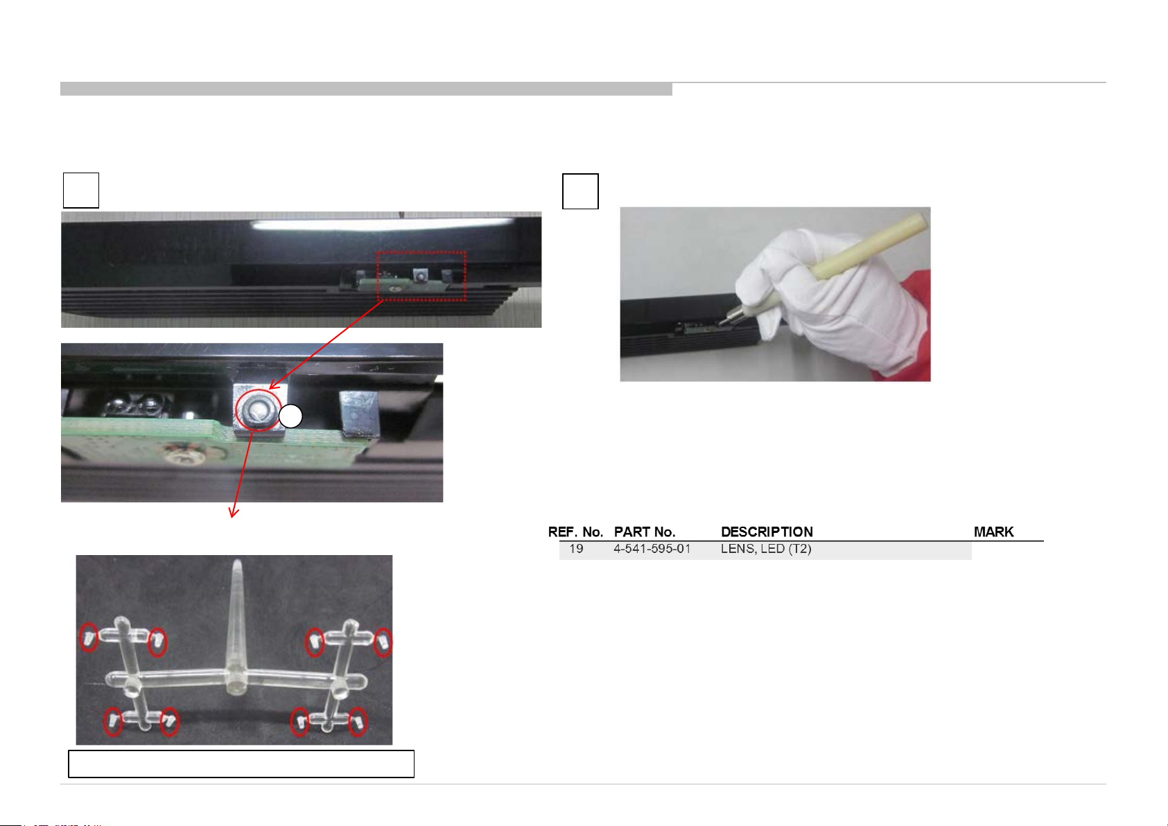
1-9. How to ass’y the LED lens [KLV-22P402B IN5 /24P412B IN5 /24P422B IN5 /24P412B SP1]
1
The LED lens is installed in the hole
19
2
Press the LED lens in the hole
The LED lens is remarked with red circle
KLV-22P402B/24P412B/24P42 2B (IND/RMD)
31
Page 32
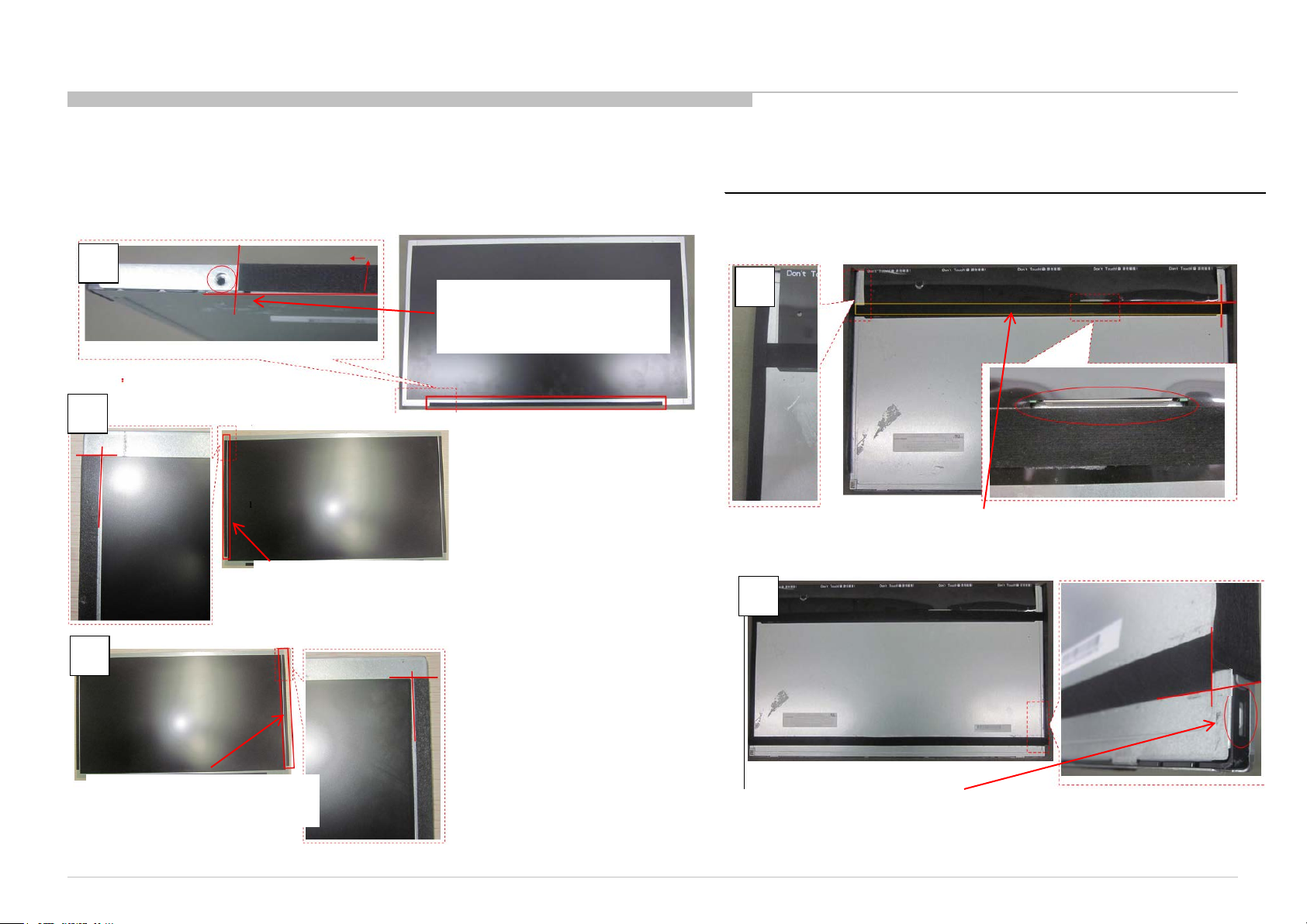
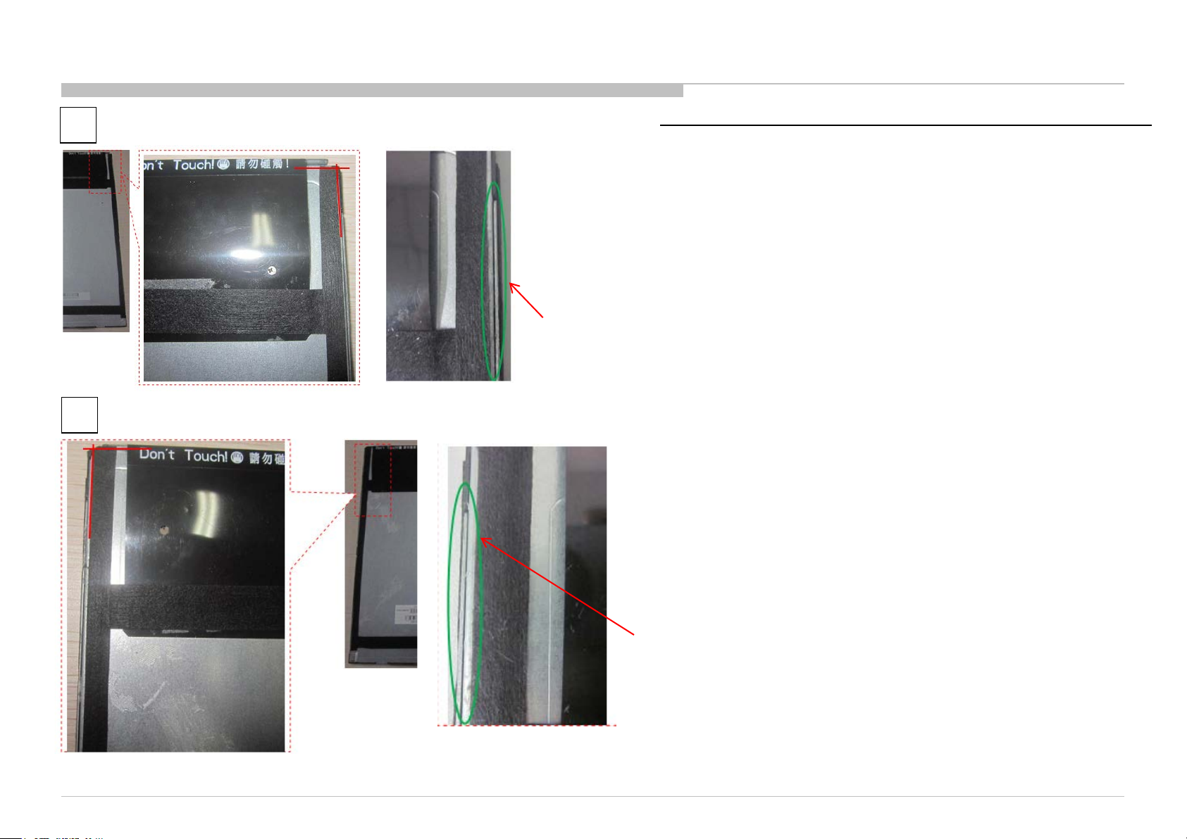
1-10. How to assemble the Himeron Countermeasure of panel
REF. No . PART No . DESCRIPTION MARK
4-541-809-01 CUSHI ON, 400 x15
4-541-811-01 CUSHI ON, 260 x12
4-541-808-01 CUSHI ON, 480 x17
[KLV-22P402B IN5/24P412B IN5 /24P422B IN5/24P412B SP1]
1-10-1. KLV-22P402B IN5
1. Stick HIMERON (Part Number :4-541-809-01) to the b otto m side of the panel.
1
According to the graphical
position, extra width should
fold to the front of the panel
2
2. Stick HIMERON
(Part Number :4-541-811-01) along
the inside edge of th e panel iron
edge .
Flatten HIMERON for the
front/side of panel.
4
4. The above of HIMERON (Part Number :4-541-808-01) close
to the connector of LVDS, and the right of HIMERON is
pasted along the pa nel edge steps. Flatten the side of
HIMERON.
5
3
3. Stick HIMERON
(Part Number :4-541-811-01) along
the inside edge of the panel iron
edge .
Flatten HIMERON for the
front/side of panel.
KLV-22P402B/24P412B/24P42 2B (IND/RMD)
5. The bottom of HIMERON (Part Number :4-541-808-01) close to the
top of the red circle marked black rectangle. and the right of
HIMERON is pasted alo ng the panel edge steps. Flatten the side
of HIMERON.
32
Page 33
6
REF. No . PART No. DESCRIPTION MARK
4-541-810-01 CUS HION, 270 x8
7
6. Stick HIMERON (Part Number :4-541-810-01) along the top and the
inside edge of the panel .
HIMERON can’t blot out the iron edge of the panel .
7. Stick HIMERON (Part Number :4-541-810-01) along the top and the
inside edge of the panel .
KLV-22P402B/24P412B/24P42 2B (IND/RMD)
HIMERON can’t blot out the iron edge of the panel .
33
Page 34
1-10. How to assemble the Himeron Countermeasure of panel
REF. No . PART No . DESCRIPTION MARK
4-541-813-01 CUSHI ON, 480 x17
4-541-814-01 CUSHI ON, 275 x25
4-541-812-01 CUSHI ON, 525 x20
[KLV-22P402B IN5/24P412B IN5/24P422B IN5/24P412B SP1]
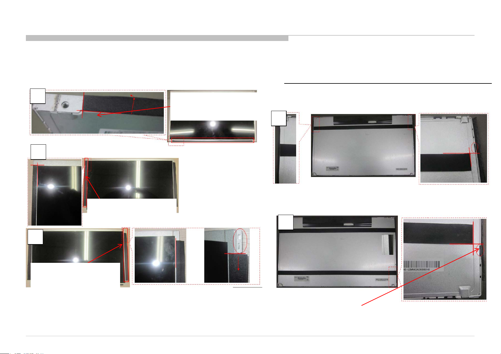
1-10-2. KLV-24P412B IN5/24P422B IN5/24P412B SP1
1. Stick HIMERON (Part Number :4-541-813-01) to the bottom side o f the panel.
3
1
2
Flatten HIMERON for the
front of panel, and the
back/side no need.
According to the graphical
position, extra width should
fold to the front of the panel
2. Stick HIMERON
(Part number :4-541-814-01)
along the inside edge of the
panel iron edge .
4
4. The above of HIMERON (PN:4-541-812-01) close to the
connector of LVDS, and the right of HIMERON is pasted
along the panel edge steps. Flatten the side of HI MERON.
5
Flatten HIMERON for the
front of panel, and the
back/side no need.
3. Stick HIMERON (Part Number :4-541-814-01) along the insi d e edge of
the panel iron edge .
KLV-22P402B/24P412B/24P42 2B (IND/RMD)
5. The bottom of HIMERON (PN:4-541-812-01) close to the top of the
red circle marked black rectangle. and the right of HIMERON is
pasted along the pa nel edge steps. Flatten the side of
HIMERON.
34
Page 35
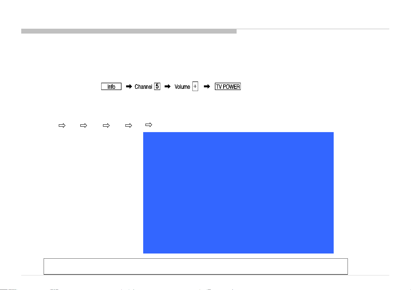
SEC 2. ADJUSTMENT
HOW TO ENTERING SERVICE MODE
1) Turn on the main po wer switch to place this set in standby mode.
2) Press the buttons on the remote commander as follows, and entering service mode.
3) Service mode display.
Or 1) Turn on the TV and switch to TV source.
2) Press the buttons on the remote commander as follows, and entering service mode.
Left Right Mute Enter Mute Volume +
3) Service mode display.
When replace Main Board or panel, please confirm " SERIAL NUMBER EDIT " and "MODEL NAME EDIT" in service mode.
If they are different, please select a suitable thing.
KLV-22P402B/24P412B/24P42 2B (IND/RMD)
Service Mode
Status Information >>
Self diagnosis history >>
NO_SIGNAL_MUTE <[ Off ]>
TUNING SYSTEM <[ AUTO ]>
Low of HPD <[ 5 ]>
SERIAL NUMBER EDIT 0000001
MODEL NAME EDIT KLV-24P422B
Test Reset <[ Off ]>
[</>]Set[Home]Exit
35
Page 36
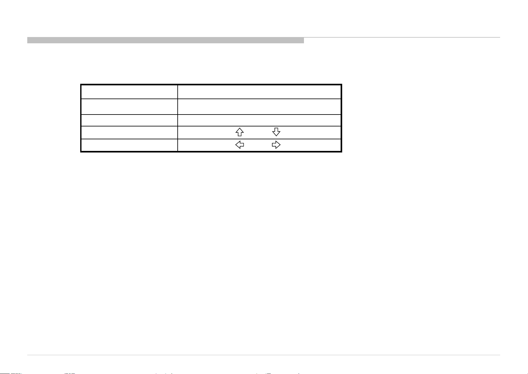
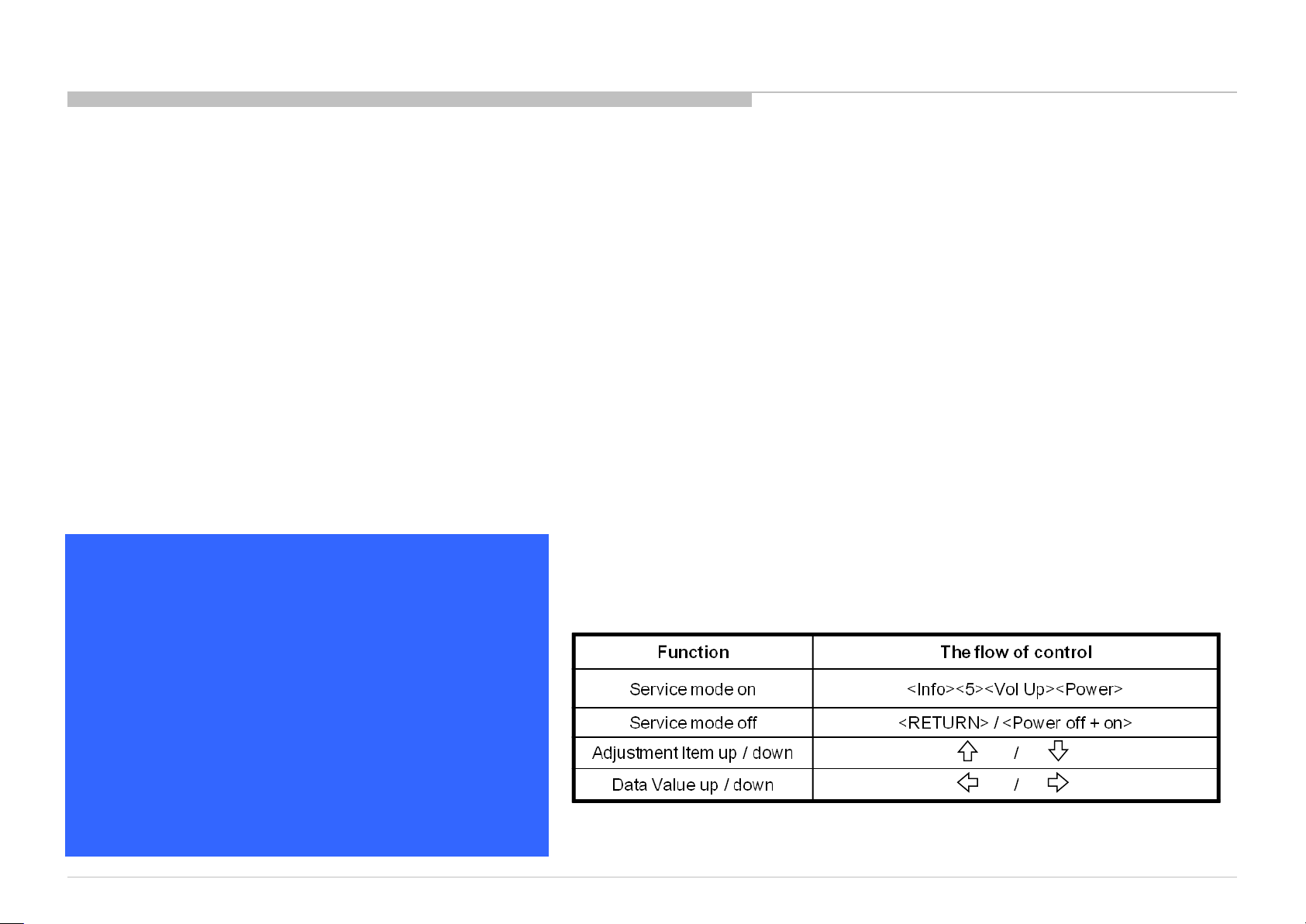
4) How to use the remote commander.
Function The flow of control
Service mode on <Info><5><Vol Up><Power>
Service mode off <Home> / <Power off + on>
Adjustment Item up / down /
Data Value up / down /
5) After entering service mode, then turn off the power switch.
ADJUSTMENT
KLV-22P402B/24P412B/24P42 2B (IND/RMD)
36
Page 37
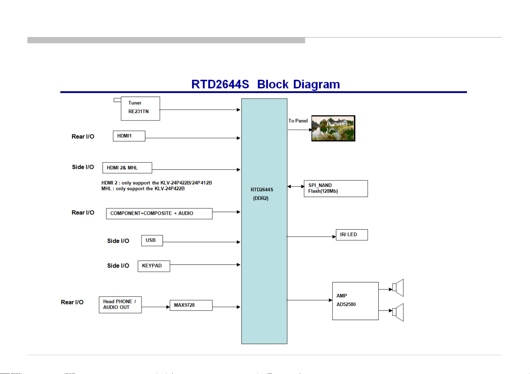
SEC 3. DIAGRAMS AND CHASSIS STRUCTURE
3-1. BLOCK DIAGRAM
3-1-1. KLV-22P402B IN5/24P412B IN5/24P422B IN5/24P412B SP1
KLV-22P402B/24P412B/24P42 2B (IND/RMD)
37
Page 38
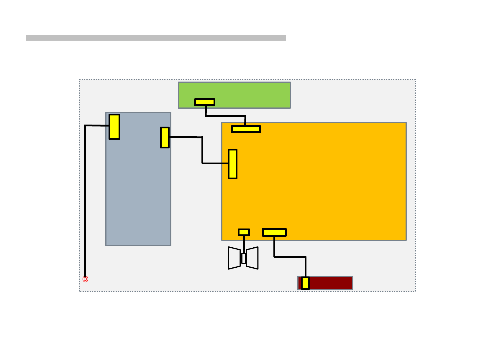
3-2. CONNECTOR DIAGRAM
3-2-1. KLV-22P402B IN5/24P412B IN5/24P422B IN5/24P412B SP1
T-Con Board
CN8601
CN408(22 inch)/CN409(24 inch)
CN9101
CN701
DIAGRAMS
Panel
Power Board
KLV-22P402B/24P412B/24P42 2B (IND/RMD)
CN601
CN401
Main Board
CN202
IR Board
38
Page 39
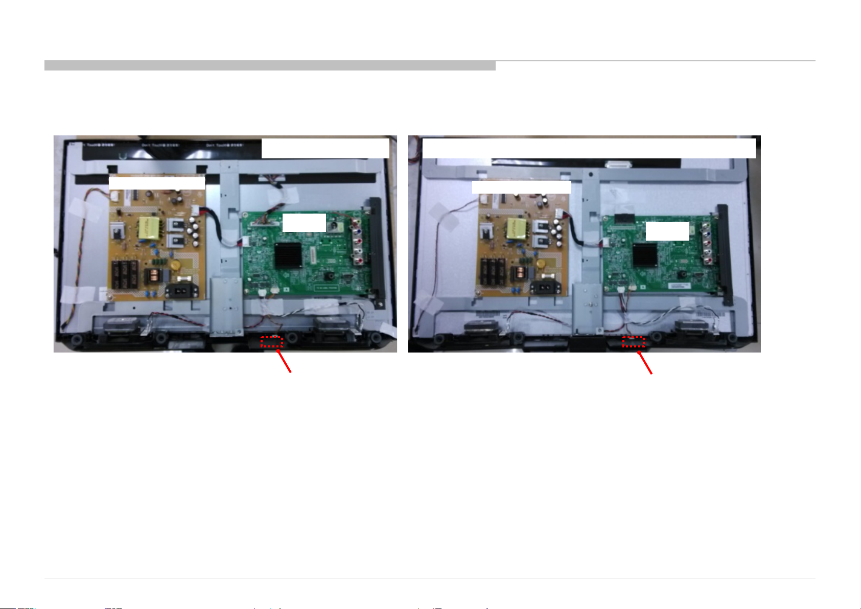
3-3. CIRCUIT BOARDS LOCATION
3-3-1. KLV-22P402B IN5/24P412B IN5/24P422B IN5/24P412B SP1
KLV-22P402B IN5 KLV-24P412B IN5 /24P422B IN5 /24P422B SP1
DIAGRAMS
POWER UNIT Board
A Board
H Board
POWER UNIT Board
A Board
H Board
KLV-22P402B/24P412B/24P42 2B (IND/RMD)
39
Page 40
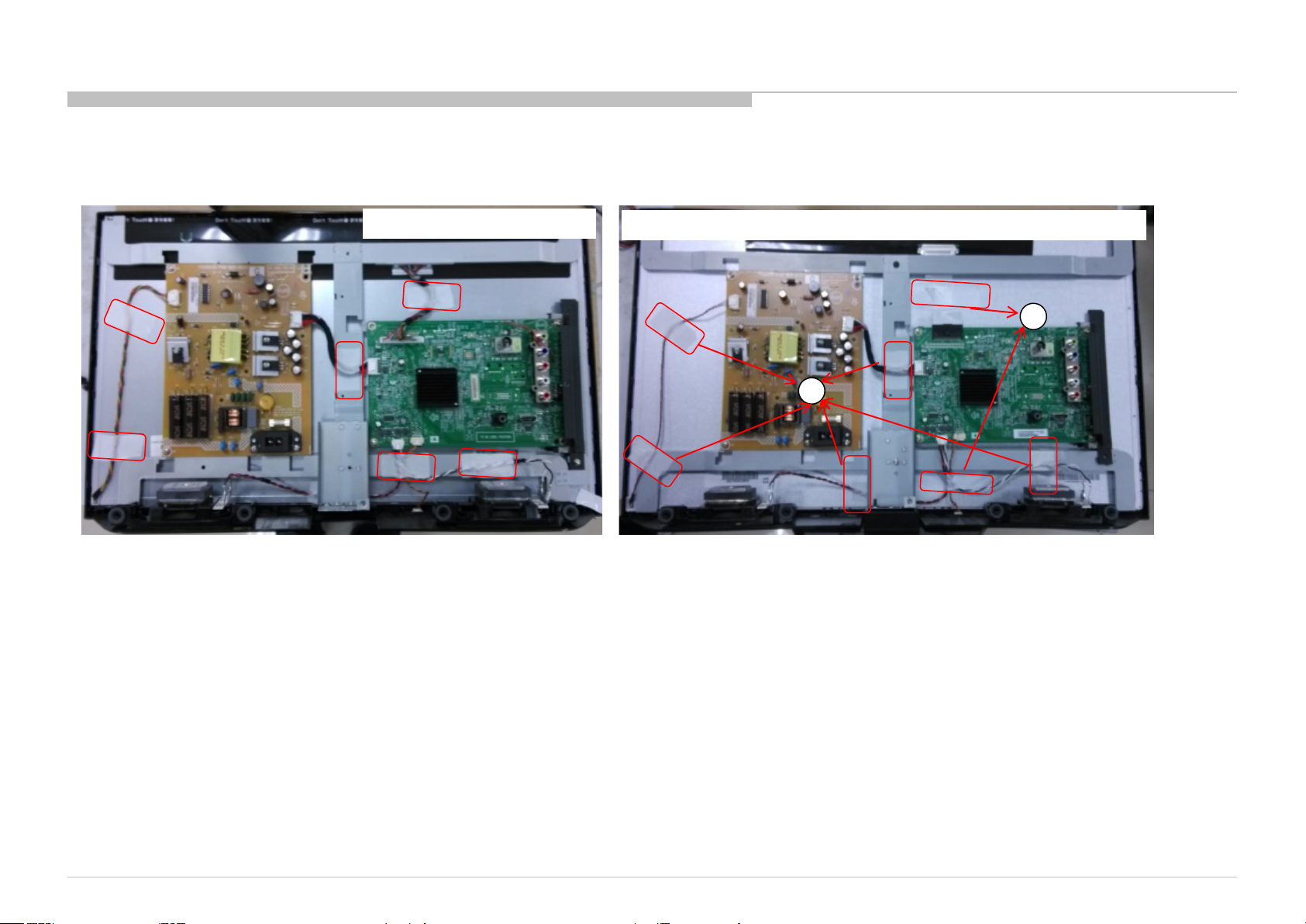
3-4. Tape location
3-4-1. KLV-22P402B IN5/24P412B IN5/24P422B IN5/24P412B SP1
DIAGRAMS
KLV-22P402B IN5
TAPE SIZE:
KLV-22P402B: 25MM*50MM
KLV-24P412B/24P422B/24P412B SP1: 1. 20MM*80MM
2. 25MM*50MM
The purpose for the tape stick is to make the cables fixed.
KLV-24P412B IN5 /24P422B IN5 /24P412B SP1
1
2
KLV-22P402B/24P412B/24P42 2B (IND/RMD)
40
Page 41

END
9-888-153-03
KLV-22P402B/24P412B/24P42 2B (IND/RMD)
Sony Corporation
41
Page 42
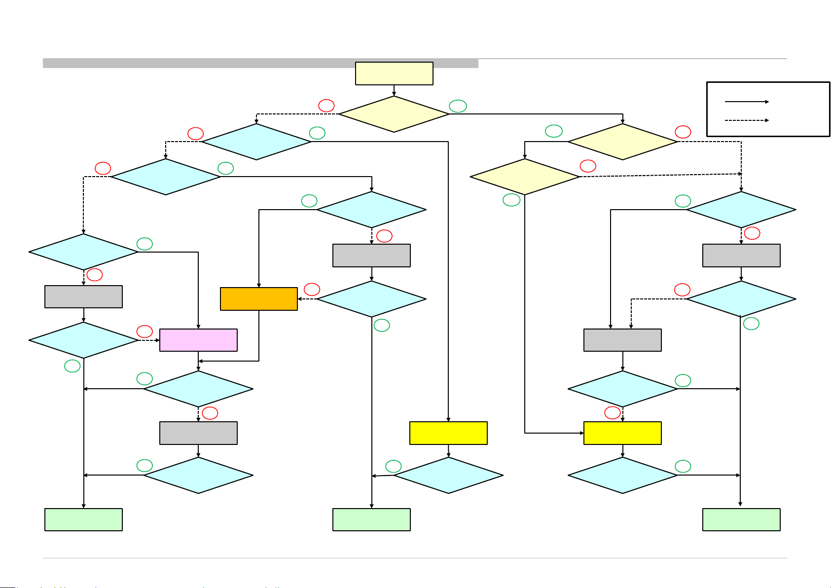
APPENDIX-1 Trouble analysis flow
Return Set
NG
Check IR Cable
Connection
NG
Reinstall
IR Cable
Check TV Function
OK
NG
Power On Key
Function check
OK
NG
Exchange
IR board
OK
Check TV Function
LED Indicator
Function check
OK
Exchange
PSU board
No
OK
OK
Does Backlight
Power Cable
connection Check
Reinstall
Power Cable
NG
Check TV Function
turn On?
NG
OK
Yes
Yes
V-Line/H-Line
Abnormal?
Yes
Does Picture
appear?
No
Exchange
Main board
Check TV Function
No
OK
Panel Cable(FFC)
Connection Check
NG
Reinstall
Panel Cable
NG
Check TV Function
OK
OK
Yes or OK
No or NG
Exchange
Main board
OK
Check TV Function
Finish R ep a ir
KLV-22P402B/24P412B/24P42 2B (IND/RMD)
NG
OK
Check TV Function
Finish R ep a ir
Exchange
Panel
NG
Exchange
Panel
OK
Check TV Function
Finish R ep a ir
42
Page 43
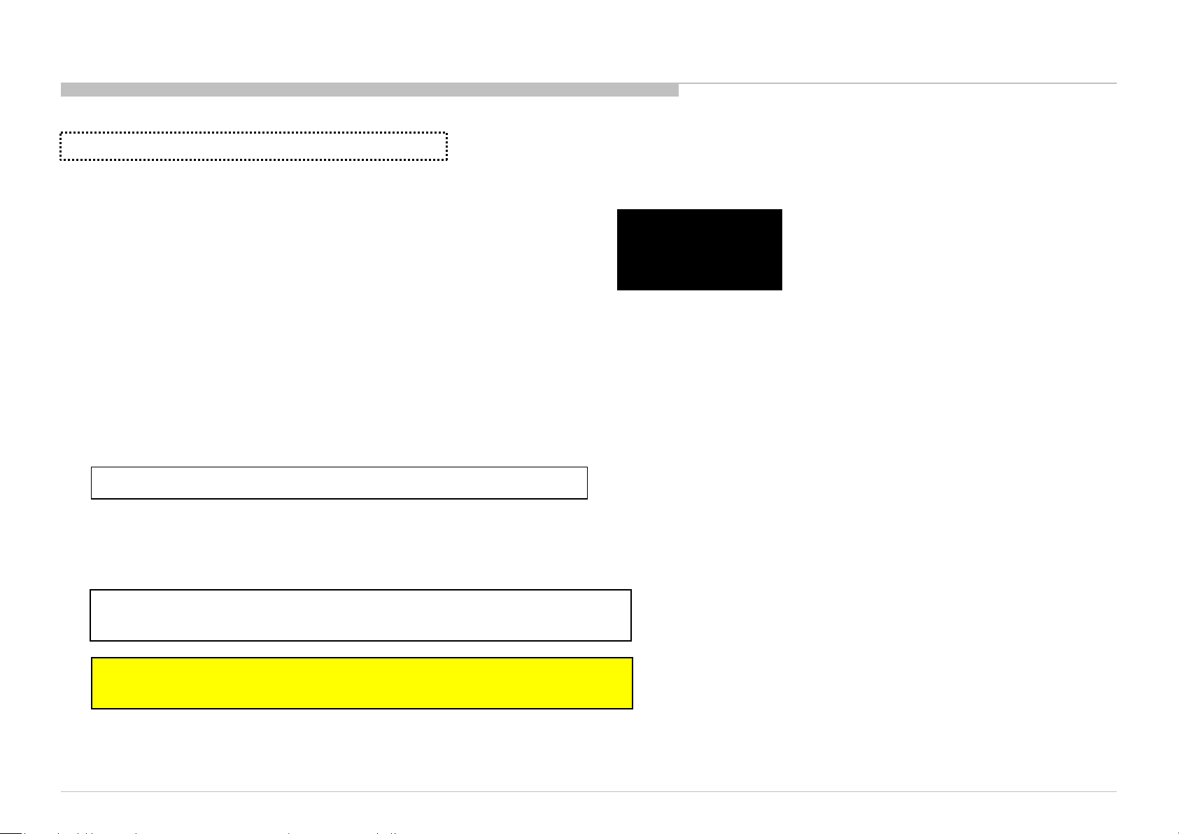
APPENDIX-2 Software data update
Chassis Name: RB2T Segment Name: MC
The confirmat ion of the software ve rsion of t he T V set.
1. Model Name
2. Serial Number
3. Software V ersion
When change Main board,
1 and 2 are not displayed.
product information of setting menu.
[HOME] , [Settings]
Please use th e latest s oft ware.
, [Set-up] , [Product Information]
1: KLV-22P402B
2: 0123450
3: 1.00
Software Down load
store the software P ac kage to U SB m emory. (Applicable USB mem ory : Format by FAT32, USB 2.0 type )
If the software file is compressed(.zip), please unzip it.
For USB, please store on ly one file f or software updat e.
KLV-22P402B IN5/24P412B IN 5 / 24P422B IN5
sony_fw_2014_XXXX_apas2.pkg (IND)
KLV- 24P412B SP1
sony_fw_2014_XXXX_apas3.pkg (RMD)
KLV-22P402B/24P412B/24P42 2B (IND/RMD)
43
Page 44
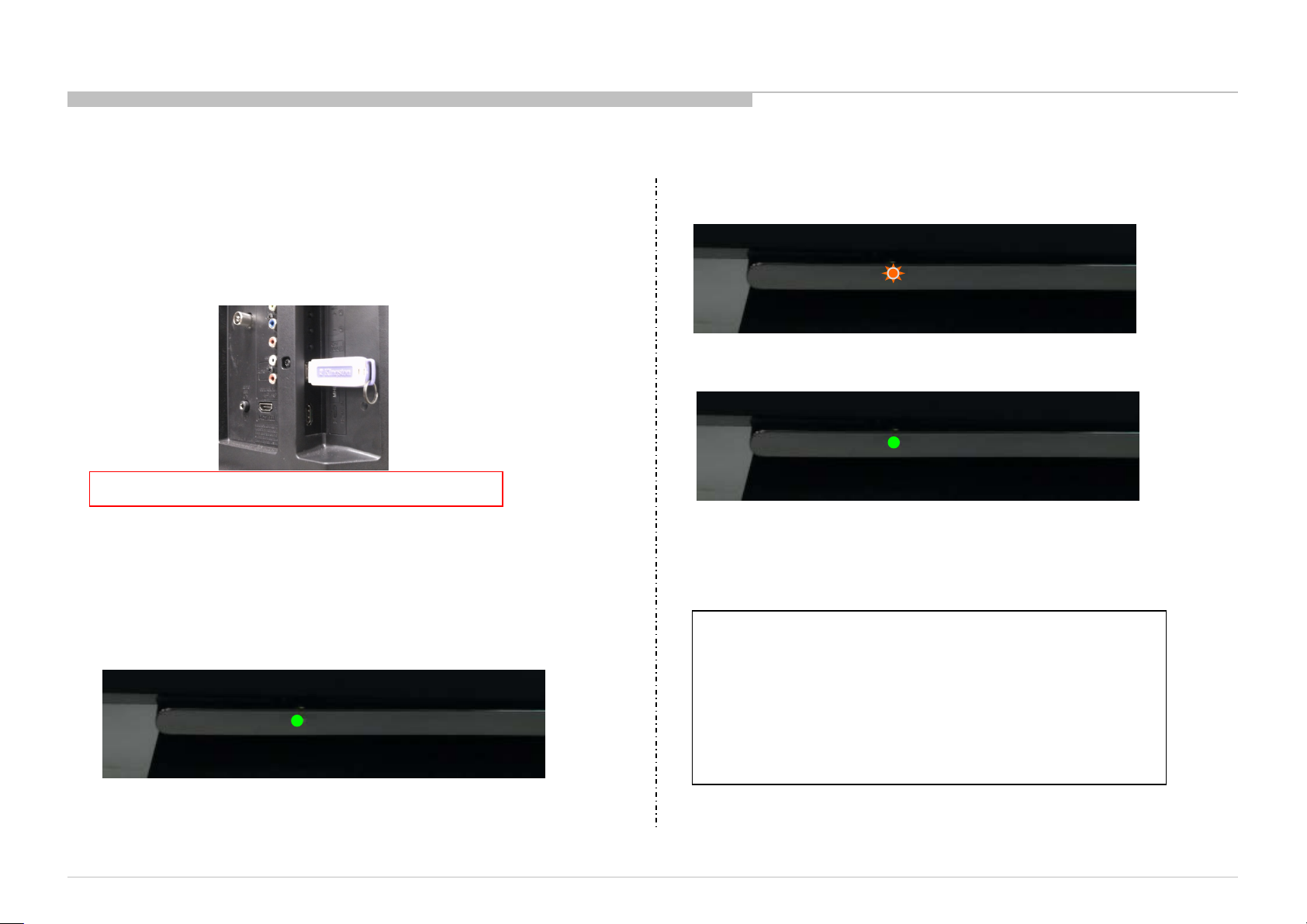
Software update by USB memory
1. T urn on the TV.
2. Unplug the AC power cord.
3. Connect USB memory .
Do not connect USB memory i n s tandby mode.
2) Starting update
Orange LED is flushing. (2-3min)
3) Finish update
Lights up Green LED again and TV is turned on.
5. Unplug AC power cord and disconnect USB memory .
4. Plug the AC power cord then start update automatically .
1) Lights up Green LED. (no picture)
KLV-22P402B/24P412B/24P42 2B (IND/RMD)
6. Plug the AC power cord then turn on the TV.
Confirm Software vers ion
Please confirm whether i t is the latest so f t ware.
product information of setting menu.
[HOME] , [Settings] , [Set-up] , [Product Information]
44
Page 45
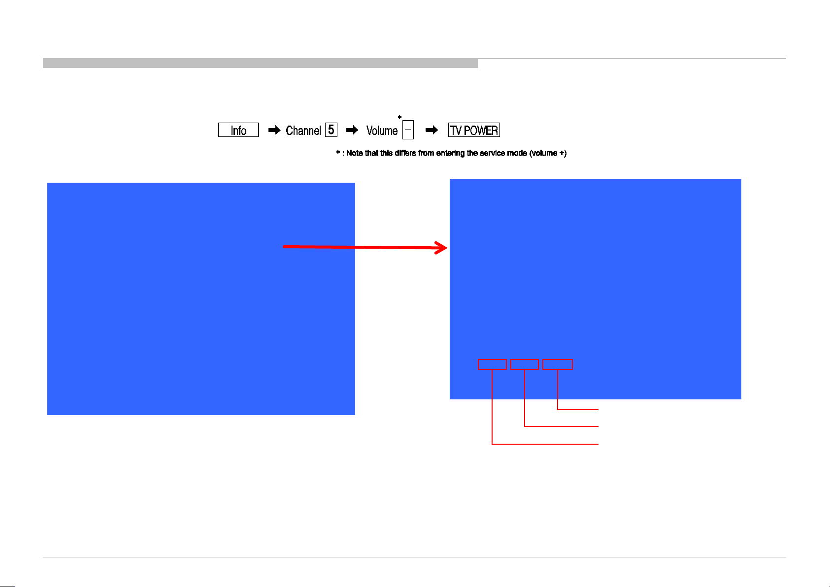
APPENDIX-3 Operation Time, Boot Count, Panel Operation Time
[To Bring Up Self Dia gnostic(SELF CHECK)]
In standby mode, press buttons on the remote commander sequentially in rapid succession as shown below:
[Operation Time, Boot Count, Panel Operation Time Sc reen]
Service Mode
Status Information >>
Self diagnosis history >>
NO_SIGNAL_MUTE <[ Off ]>
TUNING SYSTEM <[ AUTO ]>
Low of HPD <[ 5 ]>
SERIAL NUMBER EDIT 0000001
MODEL NAME EDIT KLV-24P422B
Test Reset <[ Off ]>
[</>]Set[Home]Exit
You can check the TV set operation time, boot count and panel operation time in service menu although this model doesn’t support self-diagnostics.
After you have completed the repairs, clear the result display to “0”.
Exiting the Self-diagnostic screen
To exit the Self Diagnostic screen, turn off the power to the TV by pressing the POWER button on the remote or the POWER button on the TV.
SELF CHECK
BACK <<
12345-67891-23456
[Home] Exit
Panel operation time by hour
Boot count
Total operation time by hour
KLV-22P402B/24P412B/24P42 2B (IND/RMD)
45
Page 46
APPENDIX-4 Reset and Edit Serial Number
Reset: Operation Time, Boot Count, Panel Operation Time
Edit: Serial Number
Y ou can use the Test Reset which is the Last item in the Service mode to reset the Operation Time,
Boot Count, Panel Operation Time.
Y ou can use the use the remote commander Left, Right, Up and Down to edit the Serial Number.
Edit Serial Number method:
When you select the SERIAL NUMBER EDIT item in the service mode, use right key to enter edit mode.
SERIAL NUMBER EDIT 0000001
Use the up and down key to edit the first bit of the SERIAL NUMBER (0~9)。
Use the left and right key to switch bit.
SERIAL NUMBER EDIT 0000001
( When Serial Number is “orange color in service mode after edited”, pls reset the “SN Reset” item in
F actory model for next “Serial Number Edit” pls refer to next page )
Service Mode
Status Information >>
Self diagnosis history >>
NO_SIGNAL_MUTE <[ Off ]>
TUNING SYSTEM <[ AUTO ]>
Low of HPD <[ 5 ]>
SERIAL NUMBER EDIT 0000001
MODEL NAME EDIT KLV-24P422B
Test Reset <[ Off ]>
[</>]Set[Home]Exit
KLV-22P402B/24P412B/24P42 2B (IND/RMD)
46
Page 47
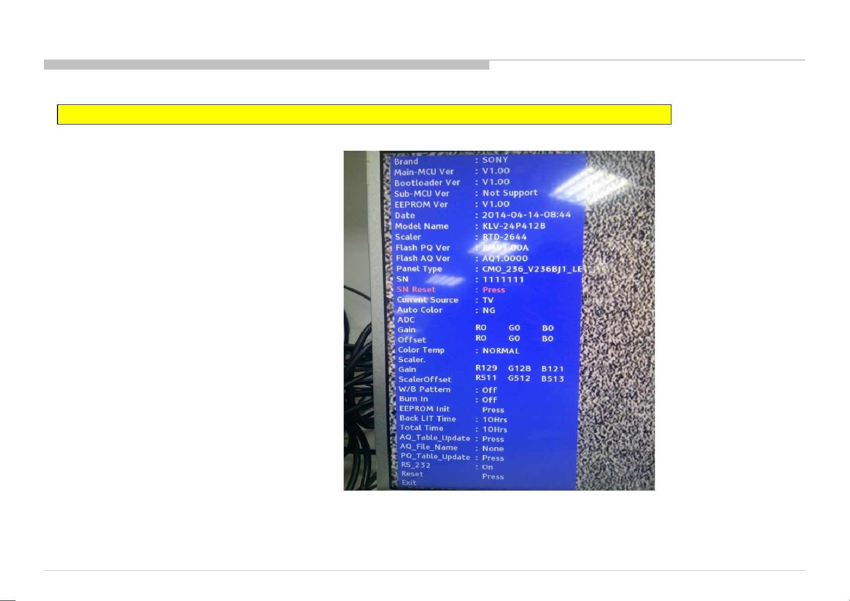
Reset Serial Number in Factory mode:
For IND Model, SN can be reset on the condition that the software is upgraded to or higher than 1.07 version ( RMD : 1.01version) if any.
1. Turn on TV. Press remote key ‘Home’ > ‘1’ > ‘9’ > ‘9’ > ‘9’ > ‘RETURN’.
W e ca n see Factory menu as below.
2. Press “Enter” key to reset SN on “SN R eset” item. Def ault v a lue is “111 111 1”.
3. Press “return” key to exit factory mode.
KLV-22P402B/24P412B/24P42 2B (IND/RMD)
47
Page 48
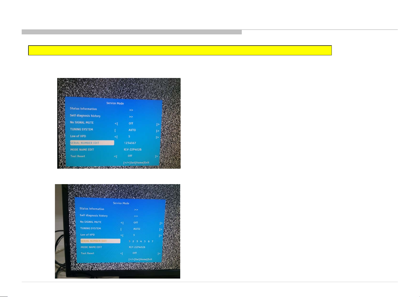
Edit Serial Number in Service Mode:
For IND Model, SN can be reset on the condition that the software is upgraded to or higher than 1.07 version ( RMD : 1.01version) if any.
1. Enter service mode
Power on then, <Left> + <Right> + <Mut e> + <Enter> + <Mute> + <Vol+>
2. Select “SERIAL NUMBER EDIT” and press <Enter> to edit. Press <Up> or <Down> to change number.
KLV-22P402B/24P412B/24P42 2B (IND/RMD)
48
Page 49
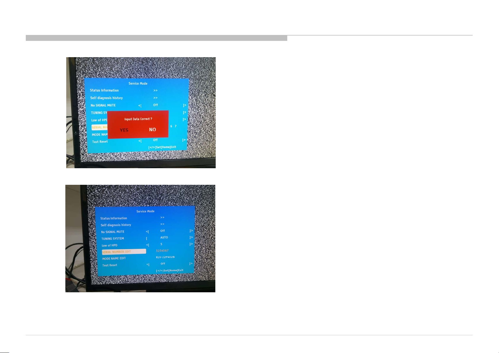
3. Press <Enter> to finish and Select “YES” to save.
4. The “SERIAL NEMBER” will not edit again when “SERIAL NUMBER” became or ange color.
5. Press <HOME> to exit “Service mode” .
KLV-22P402B/24P412B/24P42 2B (IND/RMD)
49
 Loading...