

Sony klv 15sr1a schematic
SERVICE MANUAL
SPECIFICATIONS
KLV-15SR1
US Model
Canadian Model
Television system:
American TV standard
Channel coverage:
VHF: 2-13/UHF: 14-69/CATV: 1-125
Antenna:
75 ohm external terminal for VHF/UHF
Screen size (measured diagonally):
15 inches
Panel System:
a-Si TFT Active Matrix LCD panel
(Effective dots: more than 99.99%)
Display resolution:
1024 dots (horizontal) x 768 lines (vertical)
VIDEO 1 IN:
S VIDEO IN (4-pin mini DIN):
Y: 1 Vp-p, 75-ohms unbalanced,
sync negative
C: 0.286 Vp-p (Burst signal),
75 ohms
VIDEO: 1 Vp-p, 75-ohms unbalanced,
sync negative
AUDIO: 500 mVrms (100% modulation)
Impedance: 47 kilohms
VIDEO 2 IN:
COMPONENT VIDEO (Y, PB, PR) IN:
Y: 1.0 Vp-p, 75 ohms
unbalanced, sync negative
B
: 0.7 Vp-p, 75 ohms
P
P
R
: 0.7 Vp-p, 75 ohms
Signal format: 480i
AUDIO: 500 mVrms (100% modulation)
Impedance: 47 kilohms
AUDIO OUT:
500 mVrms (100% modulation)
More than 500 mVrms at the maximum volume setting
(Variable)
More than 500 mVrms (Fixed)
Headphones:
Stereo minijack
Impedance: 16 ohms
Speaker:
50 x 90 mm (2 x 3 5/8 inches) oval speaker (2)
Speaker output:
3 W x 2, 16 ohms
LCD Colour TV

Power requirement:
120 V AC, 60 Hz
DC input:
16.5 V DC
Power consumption:
In use (Max.): 39 W
In standby: 1.9 W
Dimensions (W/H/D):
Including TV stand: 406 x 405 x 184 mm
(16 x 16 x 7
1
/4 inches)
Without TV stand: 406 x 348 x 69 mm
3
(16 x 13
/4 x 2 3/4 inches)
Mass:
Including TV stand:
5.3 kg (11 lb 11 oz)
Without TV stand: 4.5 kg (9 lb 15 oz)
Supplied accessories:
Remote control RM-917Y (1)
Batteries size AA (2)
75-ohm coaxial cable (1)
AC power cord (1)
AC power adaptor AC-FD001B (1)
Operating Instructions
Warranty Card
Optional accessories:
Note that some optional accessories may be out of
stock.
Headphones plug adaptor
Connecting cables
VMC-810S/820S, YC-15V/30V,
RK-74A, VMC-10HG, SMF-403
Wall-Mount Bracket
SU-W100
Design and specifications are subject to change
without notice.
KLV-15SR1 (UC) 2
SAFETY CHECK-OUT
After correcting the original service problem, perform the following safety checks before releasing the set to the customer:
1. Check the area of your repair for unsoldered or poorly-soldered connections. Check the entire board surface for solder
splashes and bridges.
2. Check the interboard wiring to ensure that no wires are
“pinched” or contact high-wattage resistors.
3. Check that all control knobs, shields, covers, ground straps,
and mounting hardware have been replaced. Be absolutely
certain that you have replaced all the insulators.
4. Look for unauthorized replacement parts, particularly transistors, that were installed during a previous repair. Point
them out to the customer and recommend their replacement.
5. Look for parts which, though functioning, show obvious
signs of deterioration. Point them out to the customer and
recommend their replacement.
6. Check the line cords for cracks and abrasion. Recommend
the replacement of any such line cord to the customer.
7. Check the B+ and HV to see if they are specified values.
Make sure your instruments are accurate; be suspicious of
your HV meter if sets always have low HV.
8. Check the antenna terminals, metal trim, “metallized”
knobs, screws, and all other exposed metal parts for AC
Leakage. Check leakage as described right.
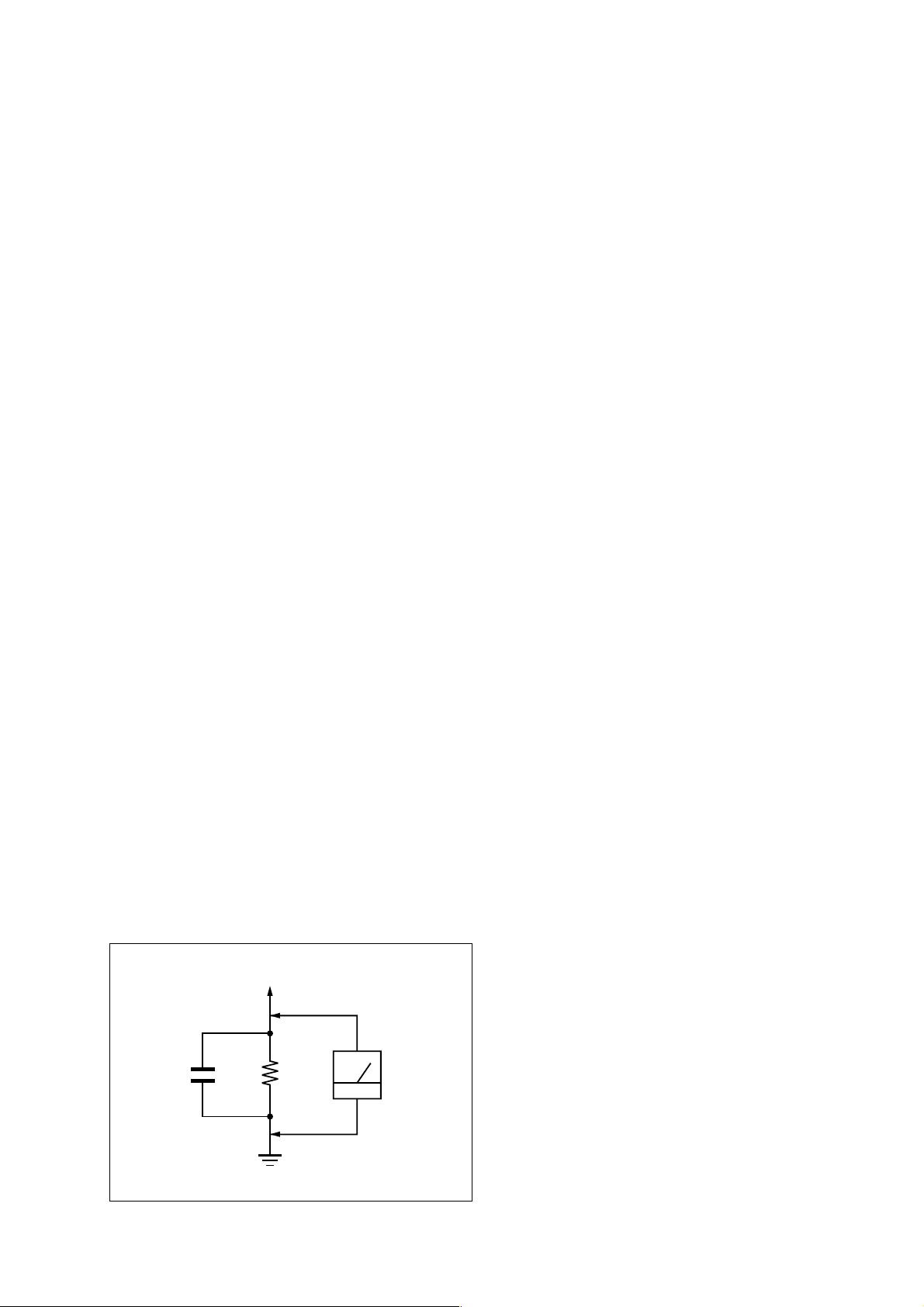
LEAKAGE TEST
The AC leakage from any exposed metal part to earth ground
and from all exposed metal parts to any exposed metal part
having a return to chassis, must not exceed 0.5 mA (500
microamperes).
Leakage current can be measured by any one of three methods.
1. A commercial leakage tester, such as the Simpson 229 or
RCA WT-540A. Follow the manufacturers’ instructions to
use these instruments.
2. A battery-operated AC milliammeter. The Data Precision
245 digital multimeter is suitable for this job.
3. Measuring the voltage drop across a resistor by means of a
VOM or battery-operated AC voltmeter. The “limit” indication is 0.75 V, so analog meters must have an accurate lowvoltage scale. The Simpson 250 and Sanwa SH-63Trd are
examples of a passive VOMs that are suitable. Nearly all
battery operated digital multimeters that have a 2 V AC
range are suitable. (See Fig. A)
WARNING!!
SAFETY-RELATED COMPONENT WARNING!!
COMPONENTS IDENTIFIED BY SHADING AND MARK
! ON THE SCHEMATIC DIAGRAMS, EXPLODED
VIEWS AND IN THE PARTS LIST ARE CRITICAL FOR
SAFE OPERATION. REPLACE THESE COMPONENTS
WITH SONY PARTS WHOSE PART NUMBERS APPEAR AS SHOWN IN THIS MANUAL OR IN SUPPLEMENTS PUBLISHED BY SONY. CIRCUIT ADJUSTMENTS THAT ARE CRITICAL FOR SAFE OPERATION
ARE IDENTIFIED IN THIS MANUAL. FOLLOW THESE
PROCEDURES WHENEVER CRITICAL COMPONENTS
ARE REPLACED OR IMPROPER OPERATION IS SUSPECTED.
AVERTISSEMENT!!
ATTENTION AUX COMPOSANTS RELATIFS À LA
SÉCURITÉ!!
LES COMPOSANTS IDENTIFIÉS PAR UNE TRAME ET
UNE MARQUE ! SONT CRITIQUES POUR LA
SÉCURITÉ. NE LES REMPLACER QUE PAR UNE
PIÈCE PORTANT LE NUMÉRO SPECIFIÉ. LES
RÉGLAGES DE CIRCUIT DONT L’IMPORTANCE EST
CRITIQUE POUR LA SÉCURITÉ DU
FONCTIONNEMENT SONT IDENTIFIÉS DANS LE
PRÉSENT MANUEL. SUIVRE CES PROCÉDURES
LORS DE CHAQUE REMPLACEMENT DE
COMPOSANTS CRITIQUES, OU LORSQU’UN
MAUVAIS FONCTIONNEMENT EST SUSPECTÉ.
To Exposed Metal
Parts on Set
0.15 µF
1.5 k
Ω
Earth Ground
AC
Voltmeter
(0.75 V)
Fig. A. Using an AC voltmeter to check AC leakage.
KLV-15SR1(UC) 3

TABLE OF CONTENTS
1. DISASSEMBLY
1-1. Rear Panel Removal ............................................ 1-1
1-2. Rear Cover Removal ........................................... 1-1
1-3. H2 Board Removal ...............................................1-2
1-4. D1 Board Removal ...............................................1-2
1-5. TU Board Removal............................................... 1-3
1-6. A and B1 Boards Removal ...................................1-3
1-7. LCD Panel Removal .............................................1-4
1-8. H5 Board Removal ...............................................1-4
1-9. H4 Board Removal ...............................................1-5
2. DIAGRAMS
5-1. Circuit Boards Location ........................................2-1
3. EXPLODED VIEWS
3-1. Chassis ...................................................................3-2
3-2. Packing Materials ..................................................3-3
4. ELECTRICAL PARTS LIST....................................4-1
KLV-15SR1 (UC) 4
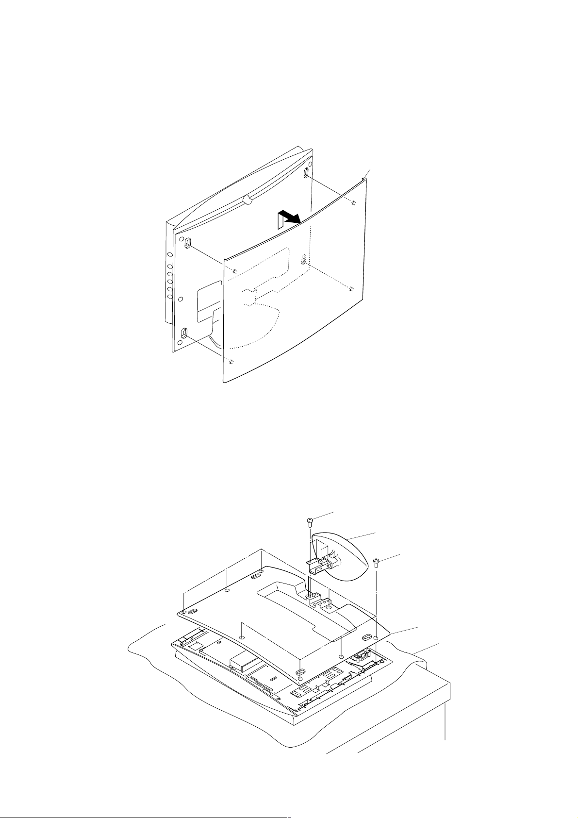
1-1.REAR PANEL REMOVAL
SECTION 1
DISASSEMBLY
1 Rear panel (15)
1-2.REAR COVER REMOVAL
1 Four screws
(+PS 4x12)
2 Stand block assy
3 Nine screws
(+BVTP 3x10)
4 Rear cover(15)
Prortection sheet
KLV-15SR1 (UC) 1-1
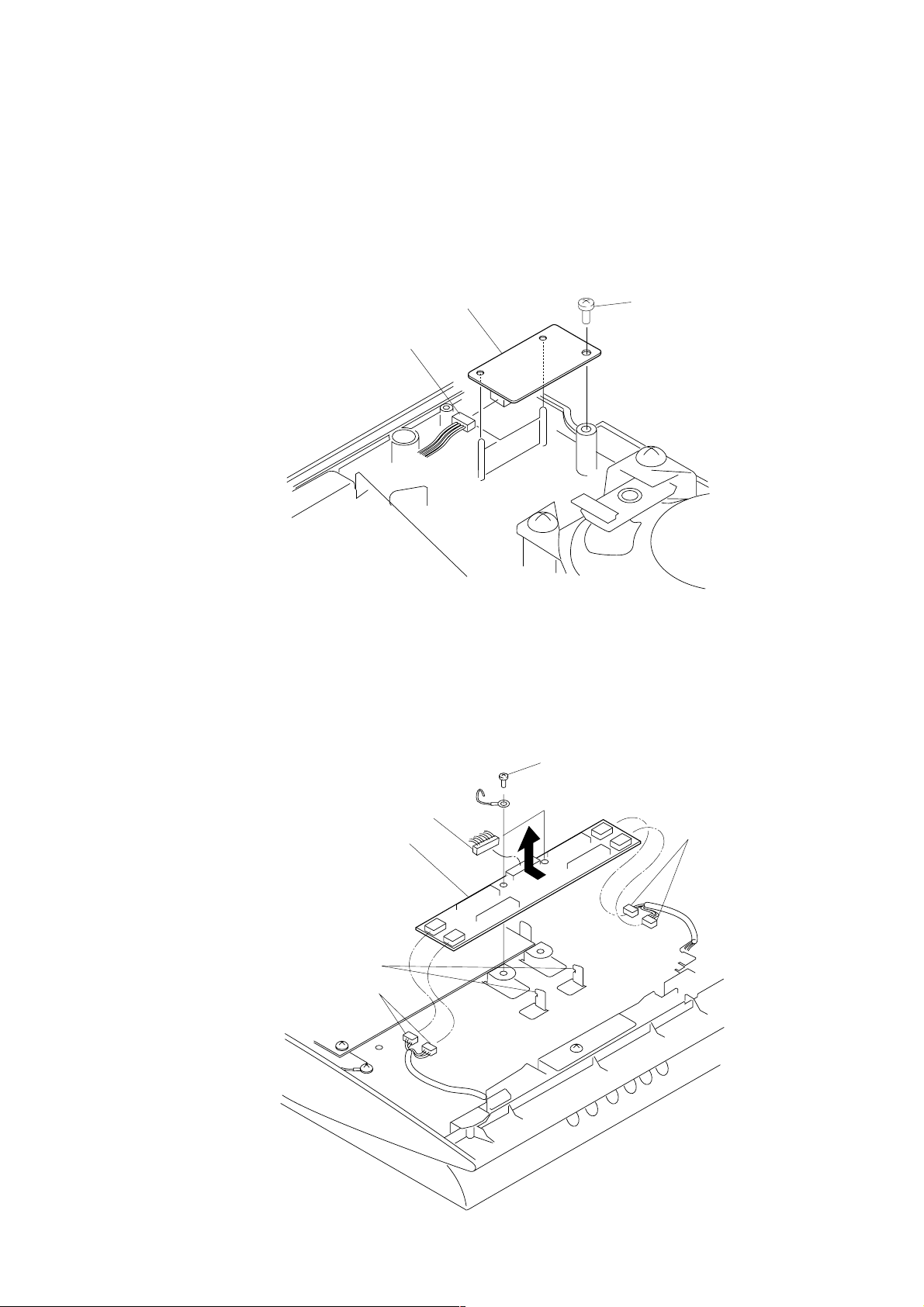
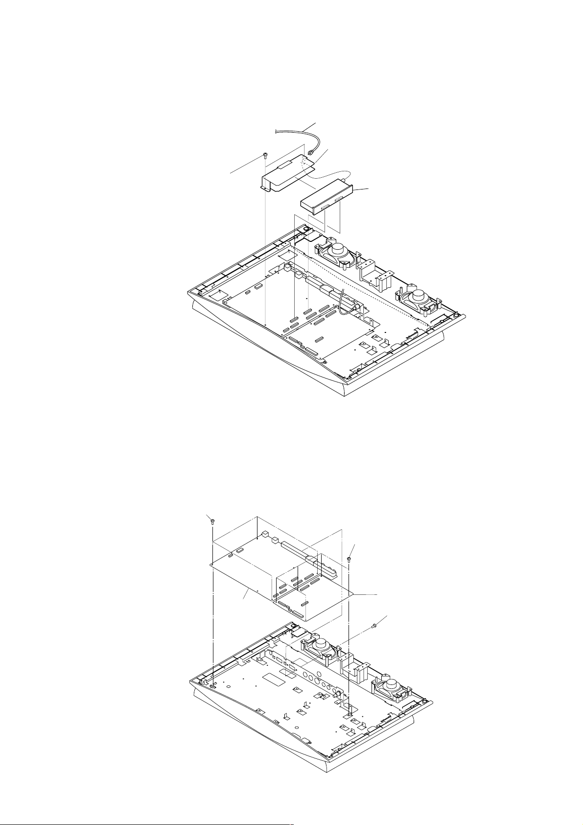
1-3.H2 BOARD REMOVAL
2 Screw
(+BVTP 3 x 10)
3 H2 board
1 Connector
CN7601
1-4.D1 BOARD REMOVAL
1 Connector
CN8002, CN8004
1 Connector
CN8001
3 D1 board
Two claws
2 Two screws
(+BVTT 3x6)
1 Connector
CN8003, CN8005
KLV-15SR1 (UC) 1-2
1-5.TU BOARD REMOVAL
2 Two screws
(+BVTT 3 x 6)
1 Connection cord
3 Tuner bracket
4 Tuner board
1-6.A AND B1 BOARDS REMOVAL
1 Four screws
(+BVTT 3x6)
3 A board
4 Five screws
(+BVTT 3x6)
5 B1 board
2 Two screws
(+BVTP 3x10)
KLV-15SR1 (UC) 1-3
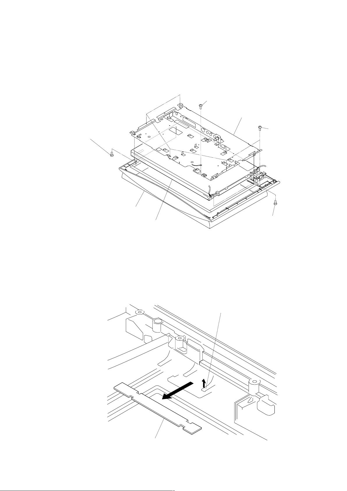
1-7.LCD PANEL REMOVAL
2 Screw
(+BVTT 3x6)
3 LCD bracket
4 Two screws
(+BVTT 3x10)
Front panel
1-8.H5 BOARD REMOVAL
5 LCD panel
1 Five screws
(+BVTP 3x8)
4 Two screws
(+BVTT x10)
1 H5 board
Claw
KLV-15SR1 (UC) 1-4
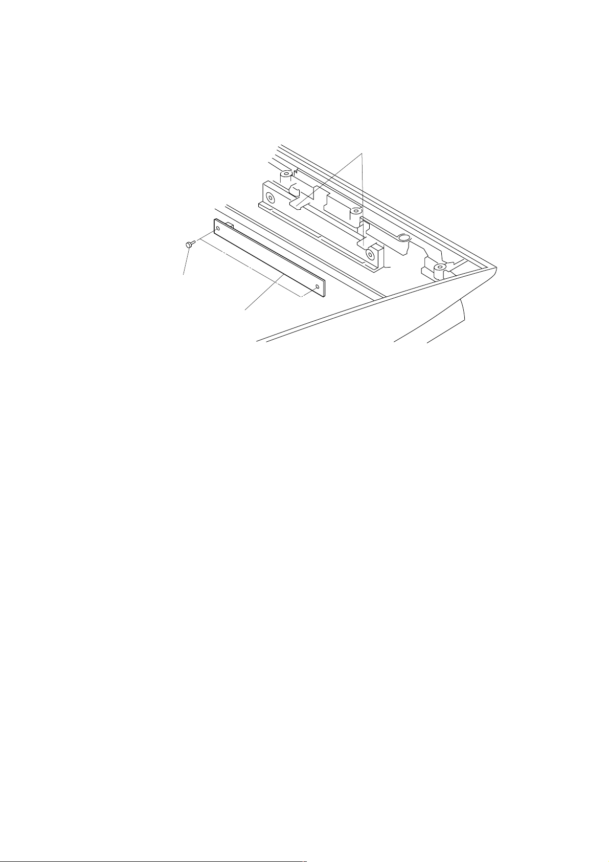
1-9.H4 BOARD REMOAVL
1 Two screws
(+BVTP 3x8)
Two claws
2 H4 board
KLV-15SR1 (UC) 1-5
E
2-1. CIRCUIT BOARD LOCATION
H4 board
H5 board
SECTION 2
DIAGRAMS
D1 board
B1 board
TU board
A board
H2 board
KLV-15SR1 (UC) 2-1

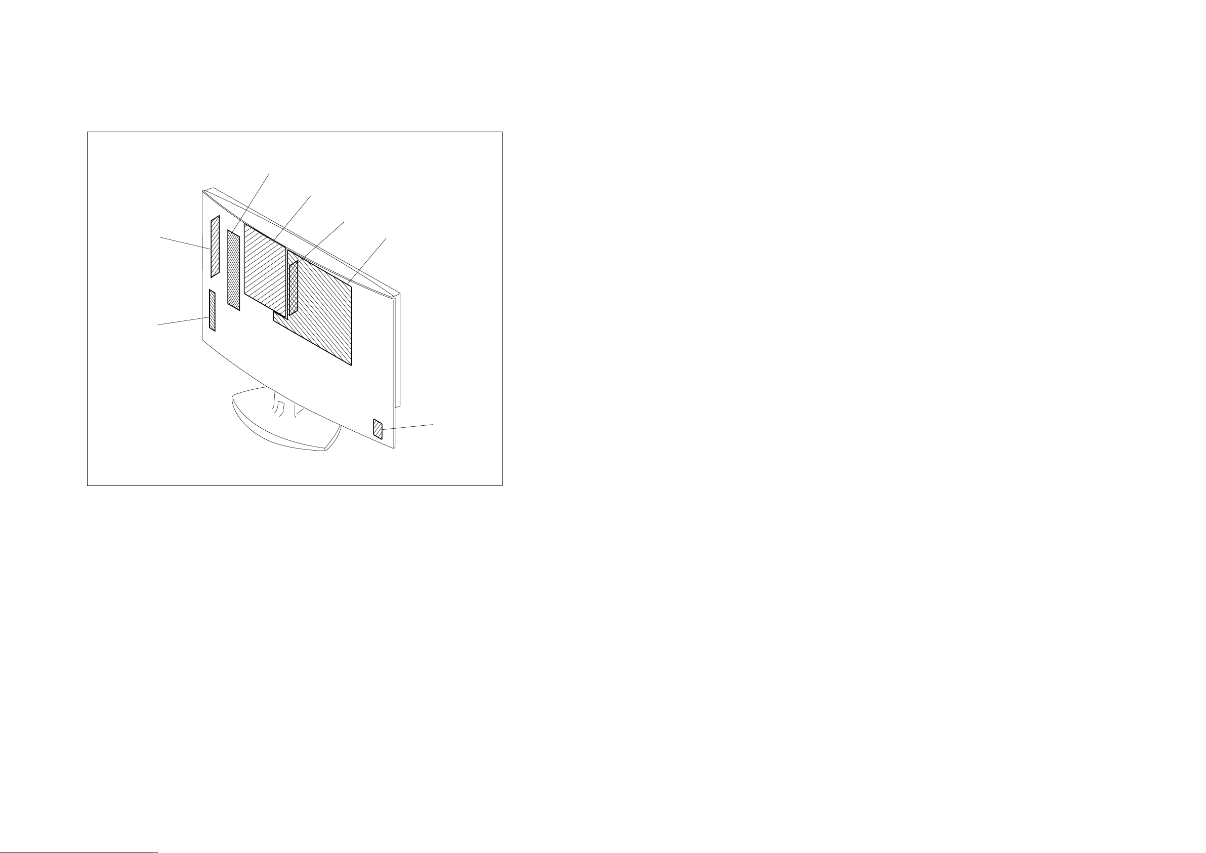
SECTION 3
EXPLODED VIEWS
NOTE:
The components identified ! marked are
critical for safety.
Replace only with the part number specified.
Les composants identifiés par la marque !
sont critiques pour la sécurité.
Ne les remplacer que par une pièce portant
le numéro spécifié.
• Items with no part number and no description are
not stocked because they are seldom required for
roution service.
• The construction parts of an assembled part are
indicated with a collation number in the remark
colum.
• Items marked " * " are not stocked since they are
seldom required for routine service. Some delay
should be anticipated when ordering these items.
KLV-15SR1(UC) 3-1
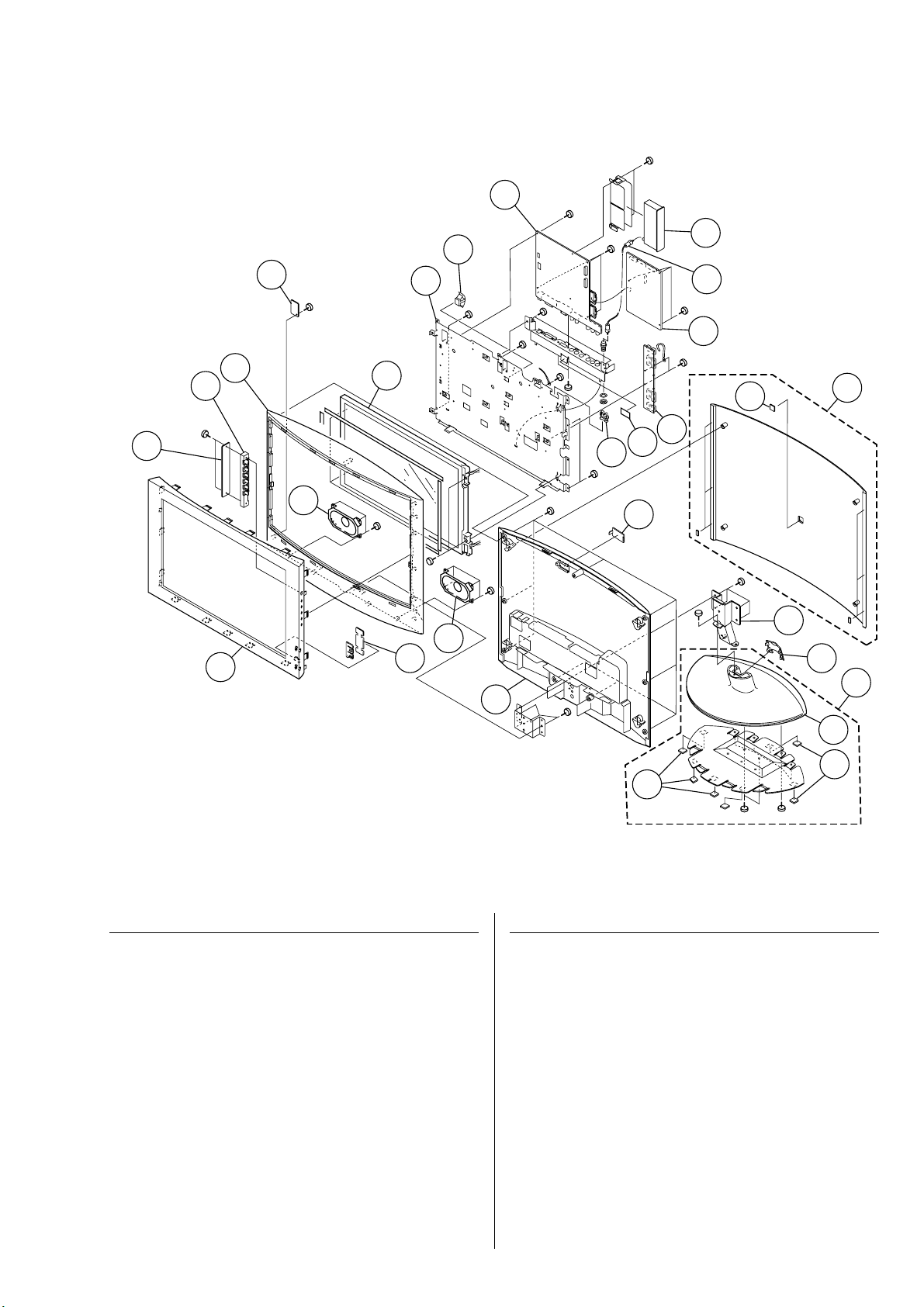
3-1.CHASSIS
#4
2
#3
3
1
4
5
#7
21
#1
6
22
23
#5
12
21
#3
#1
7
20
#4
#4
#3
#7
#4
#3
#7
#4
14
#3
25
15
11
#4
#4
10
#2
9
8
#6
19
13
16
17
18
24
REF. No. PART No. DESCRIPTIONRE MARK
1 X-4041-639-1 BEZEL ASSY (15 INCH)
2 * A-1405-263-A H4 MOUNT
3 4-089-162-11 BUTTON, MULTI
4 4-089-167-02 CABINET (15 INCH)
5 * A-1405-270-A H2 MOUNT
6 * 1-804-819-12 LCD PANEL
7 * A-1405-261-A A MOUNT
8 1-827-467-11 CORD, CONNECTION
9 * A-1405-267-A TU MOUNT
10 * A-1405-262-A B1 MOUNT
11 * 8-933-600-35 D1 MOUNT
12 * 4-069-570-01 SPACER, PWB
13 X-4040-523-2 ASSY, REAR PANEL (15 INCH) 19
14 3-383-699-01 CLAMP (EDGE)
15 4-089-160-02 COVER, ECS
16 * 4-089-178-01 HINGE
17 4-089-159-01 COVER, CABLE
19
19
#6
#3
REF. No. PART No. DESCRIPTIONRE MARK
18 X-4040-664-1 ASSY, STAND (S) 19, 24
19 3-966-650-01 FOOT, FEL T
20 4-089-171-41 COVER, REAR (15 INCH)
21 1-825-174-21 SPEAKER (5X9CM)
22 * A-1405-264-A H5 MOUNT
23 X-4040-666-1 ASSY (15 INCH), LCD BRACKET
24 4-089-170-01 BASE, ST AND
25 * 4-075-165-01 CUSHION (SP)
26 1-500-511-11 CORE, FERRITE
#1 7-685-660-79 +BVTP 4X10 TYPE2 IT-3
#2 7-685-648-79 +BVTP 3X12 TYPE2 IT-3
#3 7-685-646-79 +BVTP 3X8 TYPE2 IT-3
#4 7-685-871-01 +BVTT 3X6 (S)
#5 7-685-873-09 +BVTT 3X10 (S)
#6 7-682-663-09 +PS 4X12
#7 7-685-647-79 +BVTP 3X10 TYPE2 IT-3
KLV-15SR1(UC) 3-2
 Loading...