

Page 1
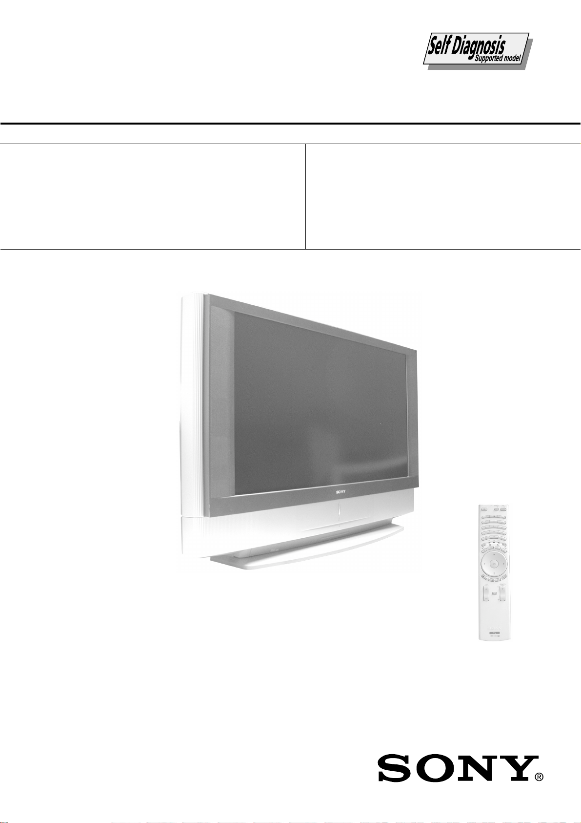
KF-50/60SX300
RM-906
SERVICE MANUAL
MODEL
KF-50SX300
KF-50SX300K
KF-50SX300U
COMMANDER DEST CHASSIS NO.
RM-906 AEP SCC-R01A-A
RM-906 OIRT SCC-R03A-A
RM-906 UK SCC-R02B-A
MODEL
KF-60SX300
COMMANDER DEST CHASSIS NO.
RM-906 AEP SCC-R01B-A
KF-60SX300K
KF-60SX300U
LE-4A
RM-906 OIRT SCC-R03B-A
RM-906 UK SCC-R02A-A
CHASSIS
KF-50/60SX300
- 1 -
RM-906
LCD PROJECTION TV
Page 2

KF-50/60SX300
RM-906
TABLE OF CONTENTS
Section Title Page Section Title Page
Caution................................................................ 3
Specifications ...................................................... 4
Connectors .......................................................... 5
1. SELF DIAGNOSIS FUNCTION
LE-4A Self Diagnostic Software........................ 6
2. GENERAL ................................................................... 7
3. DISASSEMBLY
3-1. Rear Cover Removal .......................................... 21
3-2. Centre Pillar Removal ........................................ 21
3-3. Service Position ................................................. 21
3-4. Chassis, Optical Unit, DC Fan Removal ........... 21
3-5. Power Block Removal ....................................... 22
3-6. H1 Board Removal ............................................ 22
3-7. H2 Board Removal ............................................. 22
3-8. H3 Board Removal ............................................. 22
3-9. A Board Removal ............................................... 23
3-10. G Board Removal ............................................... 23
3-11. T Board Removal ................................................ 23
3-12. Front Panel Removal .......................................... 23
3-13. Front Cover Removal ......................................... 24
3-14. Control Panel Removal ....................................... 24
3-15. Screen, Mirror Block Assembly Removal.......... 24
3-16. Mirror Cover Block Assembly Removal............ 25
3-17. Contrast Screen, Diffusion Plate Removal ......... 25
3-18. Woofer Block Assembly Removal ..................... 26
3-19. Speaker Removal ................................................ 26
3-20. Mirror Removal .................................................. 26
4. ELECTRICAL ADJUSTMENTS
4-1. Adjustments with Commander ........................... 27
4-1-1. How to Select Each Mode .............................. 27
4-1-2. Programming the Remote Commander
for Operation in Service Mode....................... 27
4-1-3. Setting the TV into Service Mode .................. 27
4-1-4. Screen Display for Service Menu .................. 27
4-1-5. Operation Method for Adjustments ............... 29
4-2. Screen Centre Adjustment .................................. 29
4-3. Test Test Mode ................................................... 29
WARNING !!
AN ISOLATION TRANSFORMER SHOULD BE USED DURING
ANY SERVICE WORK TO AVOID POSSIBLE SHOCK HAZARD
DUE TO LIVE CHASSIS, THE CHASSIS OF THIS RECEIVER IS
DIRECTLY CONNECTED TO THE POWER LINE.
5. DIAGRAMS
5-1. Block Diagram (1) .............................................. 31
Block Diagram (2) .............................................. 32
Block Diagram (3) .............................................. 33
Block Diagram (4) .............................................. 34
5-2. Circuit Boards Location ...................................... 34
5-3. Schematic Diagrams and Printed Wiring
Boards ................................................................. 34
A Board Schematic Diagram .............................. 35
A Printed Wiring Board .................................... 38
B Board Schematic Diagram............................... 39
B Printed Wiring Board .................................... 42
C Board Schematic Diagram............................... 43
C Printed Wiring Board .................................... 47
J Board Schematic Diagram................................ 49
J Printed Wiring Board ..................................... 50
G Board Schematic Diagram .............................. 51
G Printed Wiring Board .................................... 52
H1 Schematic Diagram ....................................... 53
H1 Printed Wiring Board .................................. 52
H2 Board Schematic Diagram ............................ 53
H2 Printed Wiring Board .................................. 52
H3 Board Schematic Diagram ............................ 53
H3 Printed Wiring Board .................................. 52
T Board Schematic Diagram ............................. 53
T Printed Wiring Board .................................... 52
5-4. Semiconductors .................................................. 54
5-5. IC Block Diagrams ............................................. 56
6. EXPLODED VIEWS
6-1. Screen and Cover Block ................................... 58
6-2. Cabinet Block ...................................................... 59
6-3. Main Bracket Block ............................................ 60
6-4. Picture Tube Block ............................................. 61
7. ELECTRICAL PARTS LIST .................................. 62
SAFETY-RELATED COMPONENT WARNING !!
COMPONENTS IDENTIFIED BY SHADING AND MARKED
THE SCHEMATIC DIAGRAMS, EXPLODED VIEWS AND IN THE
PARTS LIST ARE CRITICAL FOR SAFE OPERATION. REPLACE
THESE COMPONENTS WITH SONY PARTS WHOSE PART
NUMBERS APPEAR AS SHOWN IN THIS MANUAL OR IN
SUPPLEMENTS PUBLISHED BY SONY.
ON
- 2 -
Page 3
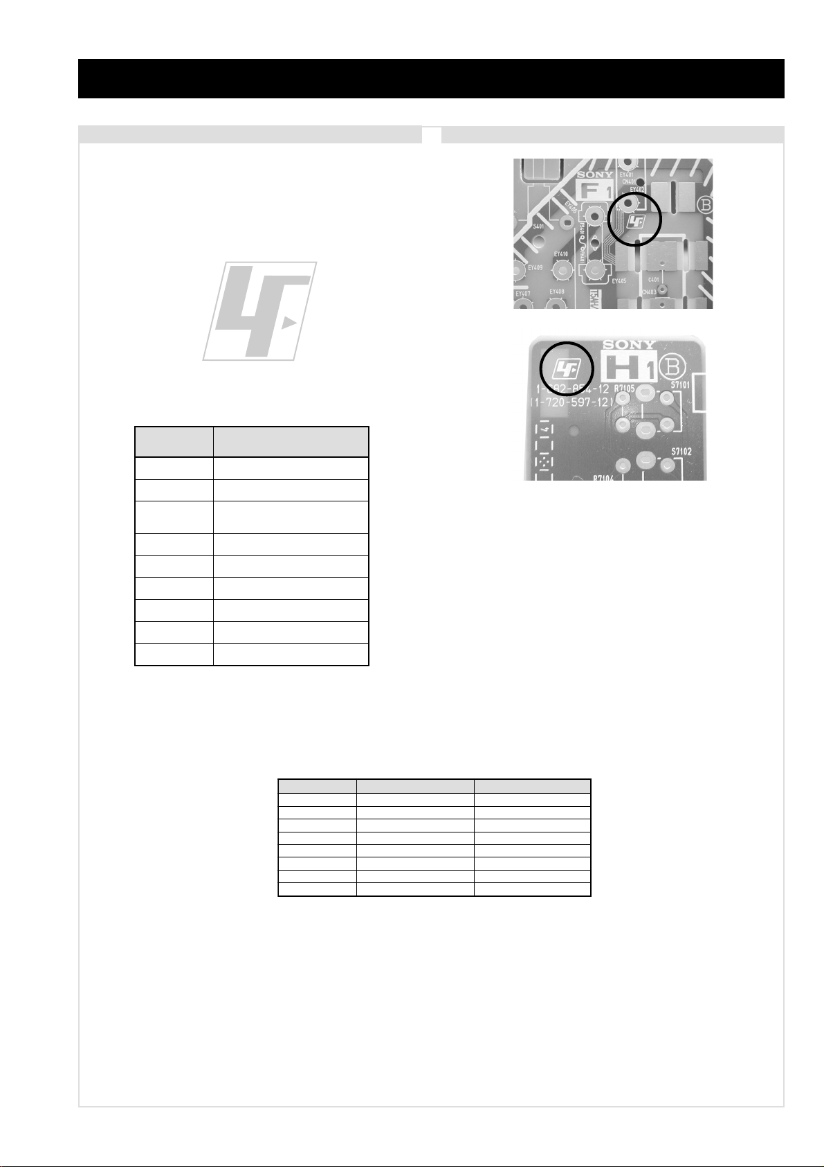
CAUTION
Lead Free Soldered Boards
The circuit boards listed below [T able 1] used in these models
may have been processed using Lead Free Solder . The boards are
identified by the LF logo located close to the board designation
e.g. F1, H1 etc [ see examples ]. The servicing of these boards
requires special precautions to be taken as outlined below .
Table 1
KF-50/60SX300
RM-906
example 1
example 2
draoB noitcnuF
AsrotalugeR,oiduA,renuT
BbmoCD3,orciM
C
GylppuSrewoP
1HscriS,yeKresU
2HsrotacidnIDEL
3HtuOPH,tupnIVA
JhctiwSV/A
ThctiwSrevoCpmaL
srevirDDCL
,ammaGlatigiD,dnekcaB,etarnacS
It is strongly recommended to use Lead Free Solder material in order to guarantee optimal quality of new solder joints. Lead Free Solder is
available under the following part numbers :
rebmuntraP retemaiD skrameR
91-500-046-7mm3.0gK52.0
02-500-046-7mm4.0gK05.0
12-500-046-7mm5.0gK05.0
22-500-046-7mm6.0gK52.0
32-500-046-7mm8.0gK00.1
42-500-046-7mm0.1gK00.1
52-500-046-7mm2.1gK00.1
62-500-046-7mm6.1gK00.1
Due to the higher melting point of Lead Free Solder the soldering iron tip temperature needs to be set to 370 degrees centigrade. This
requires soldering equipment capable of accurate temperature control coupled with a good heat recovery characteristics.
For more information on the use of Lead Free Solder, please refer to http://www.sony-training.com
- 3 -
Page 4
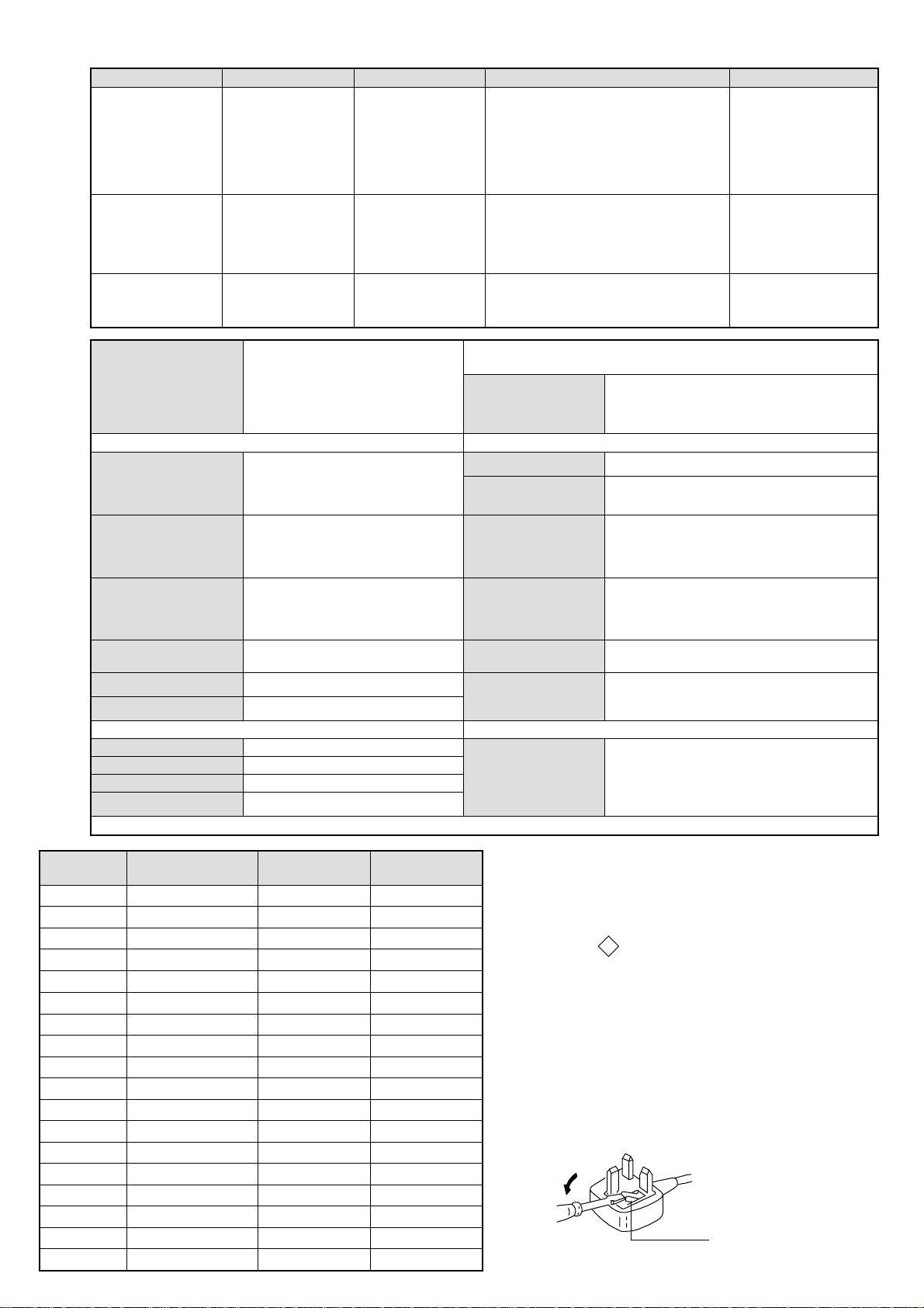
LEDOMMETI metsySnoisiveleT metsySoeretS egarevoClennahC metsySroloC
How to replace the fuse.
Open the fuse compartment with
a screwdriver blade and replace
the fuse.
FUSE
21-20E:FHV
96-12E:FHU
PEAL,I,K/D,H/G/B
TRIOK/D,H/G/B
KUI oeretSMACIN96B-12B:FHU
MACIN/NAMREG
oeretS
MACIN/NAMREG
oeretS
96-12B:I
02S-1S:VTELBAC
14S-12S:REPYH
96-12R,21-1R:K/D
96-12B:I96F-12F,Q-B,01-20F:L
21-20E:FHV
96-12E:FHU
02S-1S:VTELBAC
14S-12S:REPYH
96-12R,21-1R:K/D
KF-50/60SX300
RM-906
MACES,LAP
34.4CSTN,85.3CSTN
)NIOEDIV(
MACES,LAP
34.4CSTN,85.3CSTN
)NIOEDIV(
MACES,LAP
34.4CSTN,85.3CSTN
)NIOEDIV(
eziSerutciPdetcejorP
rotcennocoruEnip-12:1
)dradnatsCELENEC(
rotcennocoruEnip-12:2
)dradnatsCELENEC(
rotcennocoruEnip-12:3
)dradnatsCELENEC(
skcaJonohP
kcajiniM.oiduACProftupnI
rotcennocepytD.tupniCP
kcajenohpdaeHkcajinimoerets
stupnioiduAskcajonohp
stupnioediVskcajonohp
tupnioediVSNIDnip4
)sehcni05(mc721xorppA
derusaemerutcipmc721xorppA(
003XS05-FK)yllanogaid
)sehcni06(mc351xorppA
derusaemerutcipmc351xorppA(
003XS06-FK)yllanogaid
]RAER[slanimreTtuptuO/tupnI snoitacificepSlareneG
.slangisoediVdnaoiduArofstupnI
.BGRrofstupnI
oiduAdnaoediVVTfostuptuO
.slangis
.slangisoediVdnaoiduArofstupnI
.BGRrofstupnI
oiduAdnaoediVrotinoMfostuptuO
.slangis
.slangisoediVdnaoiduArofstupnI
.oediVSrofstupnI
slangisoiduAdnaoediVrofstuptuO
.ecafretnikniltramS.)elbatceles(
oiduArofelbairavsrotcennoCtuptuO
.slangiS
]TNORF[slanimreTtuptuO/tupnI lortnocderarfnI:metsyslortnocetomeR
tuptuOdnuoS
rekaepstfeLdnathgiR
refoowbuS
stnemeriuqeRrewoPV042-022
ybdnatS
snoisnemiD
thgieW
/noitpmusnoCrewoP
)003XS05-FK(gk5.73xorppA
)003XS06-FK(gk5.84xorppA
seirosseccAdeilppuS
serutaeFrehtO
stnemeriuqerrewoP
cdV3
noitangisedCEIseirettab2
)AAAezis(30RL
.ecitontuohtiwegnahcottcejbuserasnoitacificepsdnangiseD
)SMR(W01x2)rewoPcisuM(W02x2
)SMR(W51x1)rewoPcisuM(W03x1
)003XS05-FK(W1</W012xorppA
)003XS06-FK(W1</W012xorppA
)003XS05-FK(MM244x329x6731xorppA
)003XS06-FK(mm245x2601x8161xorppA
)1(rednammoCetomeR609-MR
)2(yrettab6RdetangisedCEI
,PAP,weiVtxeN,txeteleT,retliFbmoClatigiD
,MACIN,EBBlatigiD,ybloDlautriV,kniltramS
.noitcetedotuametsysVT,ICA
metI
PAPNONONO
emaNledoM
bmoClaPNONONO
ytiroirPBGRNONONO
xoBrefooWNONONO
1tracSNONONO
2tracSNONONO
3tracSNONONO
)4(nitnorFNONONO
rotcejorPNONONO
G/BmroNNONOFFO
ImroNNOFFONO
K/DmroNNONOFFO
SUAmroNFFOFFOFFO
LmroNNOFFOFFO
TASmroNFFOFFOFFO
MmroNFFOFFOFFO
txeteleTNONONO
maciNNONONO
PEA003XS06/05-FK K003XS06/05-FK U003XS06/05-FK
WARNING (UK Models only)
The flexible mains lead is supplied connected to a B.S. 1363 fused
plug having a fuse of 5 AMP rating. Should the fuse need to be
replaced, use a 5AMP FUSE approved by ASTA to BS 1362, ie one
that carries the
IF THE PLUG SUPPLIED WITH THIS APPLIANCE IS NOT SUITABLE FOR THE OUTLET SOCKETS IN YOUR HOME, IT SHOULD
BE CUT OFF AND AN APPROPRIATE PLUG FITTED. THE PLUG
SEVERED FROM THE MAINS LEAD MUST BE DESTROYED AS A
PLUG WITH BARED WIRES IS DANGEROUS IF ENGAGED IN A
LIVE SOCKET.
When an alternative type of plug is used, it should be fitted with a
5 AMP FUSE, otherwise the circuit should be protected by a 5AMP
FUSE at the distribution board.
- 4 -
ASA
T
mark.
Page 5
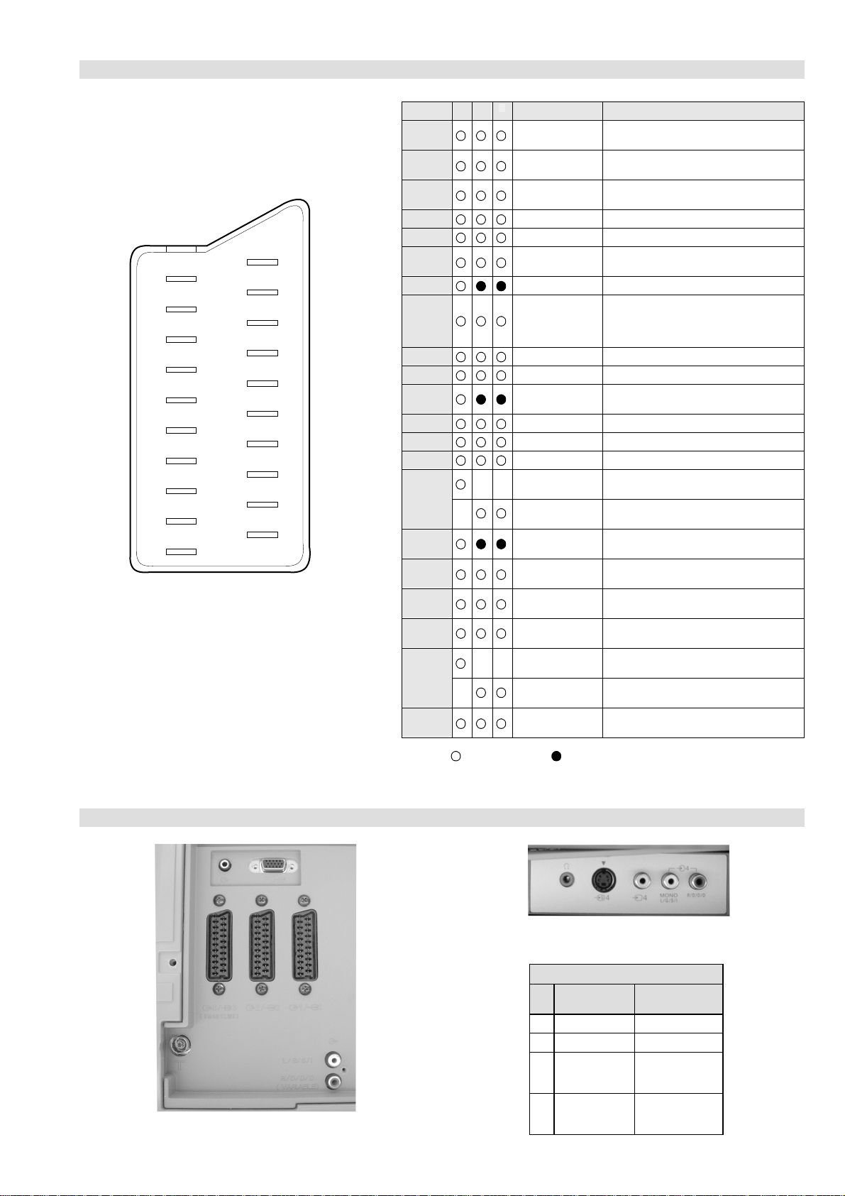
21 pin connector
KF-50/60SX300
RM-906
21
19
17
15
13
11
9
7
5
3
1
20
18
16
14
12
10
8
6
4
2
Pin No 1 2 4 Signal Signal level
1 Audio output B
2
3
4 Ground (audio)
5 Ground (blue)
6 Audio input A
7 Blue input 0.7 +/- 3dB, 75 ohms positive
8 Function select
9 Ground (green)
10 Open
11 Green Green signal : 0.7 +/- 3dB, 75 ohms,
12 Open
13 Ground (red)
14 Ground (blanking)
15
16 Blanking input
17 Ground (video
18 Ground (video
19 Video output 1V +/- 3dB, 75ohms, positive sync 0.3V
20
21 Common ground
3
(right)
Audio input B
(right)
Audio output A
(left)
(left)
(AV control)
_ _ Red input 0.7 +/- 3dB, 75 ohms, positive
_ (S signal Chroma
input)
(Ys signal)
output)
input)
_ _ Video input 1V +/- 3dB, 75ohms, positive sync 0.3V
_ Video input
Y (S signal)
(plug, shield)
Standard level : 0.5V rms
Output impedence : Less than 1kohm*
Standard level : 0.5V rms
Output impedence : More than 10kohm*
Standard level : 0.5V rms
Output impedence : Less than 1kohm*
Standard level : 0.5V rms
Output impedence : More than 10kohm*
High state (9.5-12V) : Part mode
Low state (0-2V) : TV mode
Input impedence : More than 10K ohms
Input capacitance : Less than 2nF
positive
0.3 +/- 3dB, 75 ohms, positive
High state (1-3V) Low state (0-0.4V)
Input impedence : 75 ohms
(-3+10dB)
(-3+10dB)
1V +/- 3dB, 75ohms, positive sync 0.3V
(-3+10dB)
Connected Not Connected (open) * at 20Hz - 20kHz
Rear Connection Panel Front Connection Panel
S-Video
socket
niP
oN
1dnuorG2dnuorG3tupni)langisS(Y,mho57Bd3-/+V1
4tupni)langisS(CBd3-/+V3.0
langiS leveLlangiS
noitarugifnocniptekcosoediVS
V3.0.cnySevitisop
Bd01+3-
evitisop,mho57
.cnyS
- 5 -
Page 6
KF-50/60SX300
RM-906
SECTION 1 SELF DIAGNOSIS FUNCTION
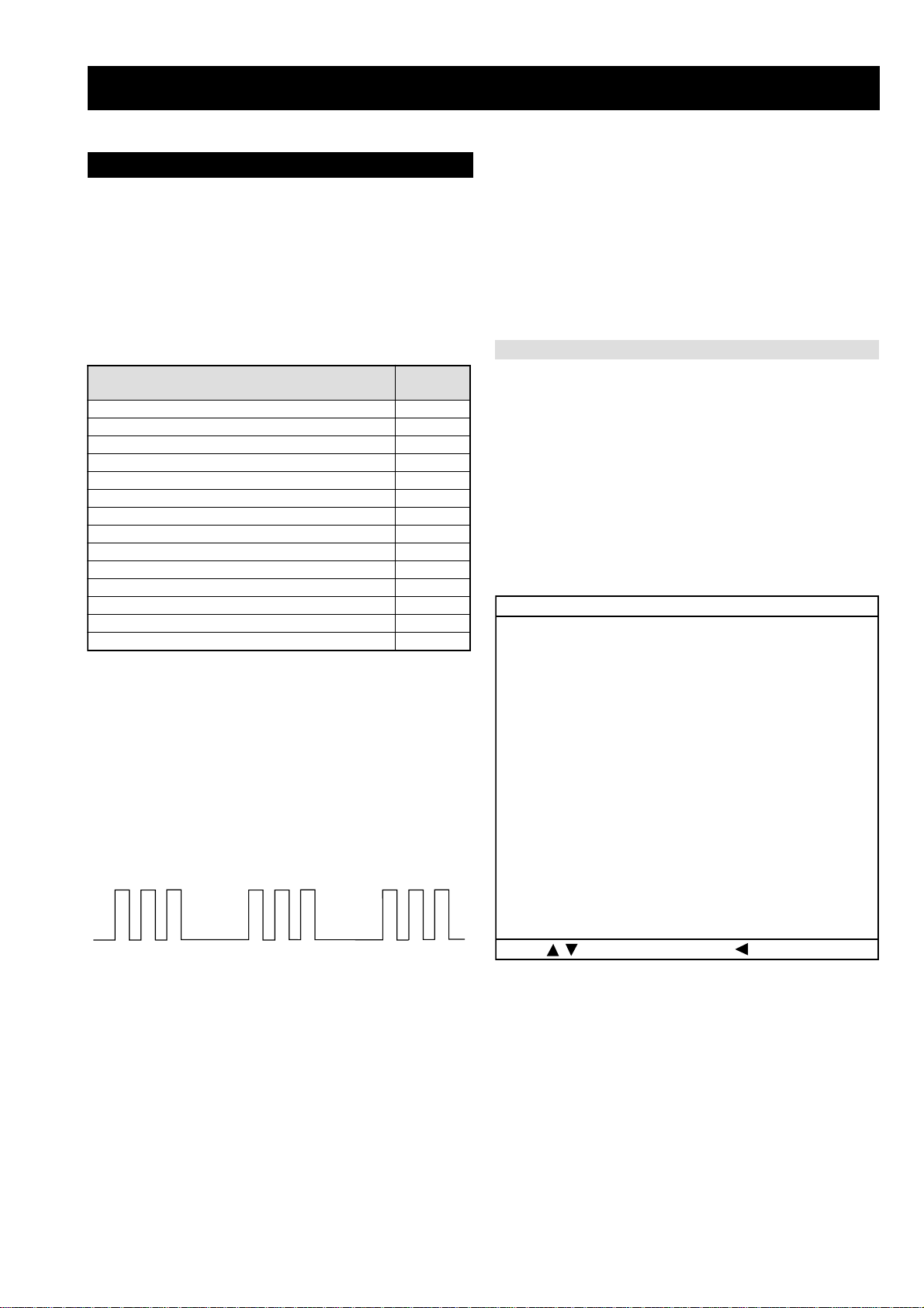
LE-4A Self Diagnostic Software
The identification of errors within the LE-4A chassis is triggered in one of two ways :- 1: Busy or 2: Device failure to respond to IIC. In the
event of one of these situations arising the software will first try to release the bus if busy (Failure to do so will report with a continuous
flashing LED) and then communicate with each device in turn to establish if a device is f aulty . If a device is found to be faulty the rele v ant
device number will be displayed through the LED (Series of flashes which must be counted) See table 1, non fatal errors are reported using this
method. Each time the software detects an error it is stored within the NVM. See T able 2.
Table 1
egasseMrorrE
voCpmaL20
torPpmaL30
torPnaF40
torPpmeT50
CII60
MVN70
renuT90
dnuoS01
etarnacS21
dnekcaB41
hctiwSVA71
ammaGlatigiD22
srevirDDCL32
torPrekaepS42
Flash Timing Example : e.g. error number 3
StBy LED
ON ON ON
OFF
OFF
How to enter into T able 2
DEL
edoC
1. Turn on the main power switch of the TV set.
2. Program Remote Commander for Operation in Service
Mode. [See Page 27].
3. Press ‘VIDEO’ ‘VIDEO’ > ‘MENU’ on the Remote
Commander.
4. Using the Remote Commander, Scroll to the ‘Error Menu’
item using the down arrow ke y, then press the right arrow
key.
5. The following table will be displayed indicating the error
count.
Table 2
rotinomrorrE
)setuniM:sruoH(:EMITGNIKROW
:sretnuocrorrE
VOCPMAL:20E54
TORPPMAL:30E8
TORPNAF:40E55
TORPPMET:50E0
CII:60E0
MVN:70E0
RENUT:90E2
DNUOS:01E0
ETARNACS:21E4
DNEKCAB:41E2
HCTIWSVA:71E01
AMMAGLATIGID:22E3
srevirDDCL:32E6
TORPREKAEPS:42E0
33:28
:tceleS:uneMsuoiverP
Note: T o clear the error count data press ‘80’ on the Remote
commander.
- 6 -
Page 7
SECTION 2 GENERAL
KF-50/60SX300
RM-906
press this button to switch your VCR or DVD on or off.
use.
the TV switches automatically into standby mode.
• After 15 minutes without TV signal and without any button being pressed,
• To save energy we recommend switching off completely when TV is not in
lights up). Press again to switch on TV from standby mode.
Press this button to temporarily switch off TV (the standby indicator on the TV
1 TV I/ : To Temporarily Switch Off TV (standby mode):
2
1
ws
wd
wf
Overview of Remote Control Buttons
VCR or DVD on/off:
2
5
4
3
w;
wa
of the source appears on the TV screen. Refer to page 25.
3 Selecting input source: press this button repeatedly until the desired input symbol
6
7
qk
ql
these buttons to select channels. For double-digit programme numbers, enter the
4 Selecting broadcast channels: if Media Selector (w; is switched to TV, press
9
8
qj
second digit within 2.5 seconds.
button to select double-digit channels for Sony's VCR e.g. 23, press -/-- first and next
5 Selecting VCR double-digit: if Media Selector (w;) is switched to VCR, press this
q;
qg
qh
the buttons 2 and 3.
qf
If Media Selector (w;) is switched to VCR, press this button to record programmes.
b) Resetting to factory set levels:
6 a) Recording button:
qa
qd
factory default levels. This will also return the set to the install condition and the
Press, for a minimum of 3 seconds, to return the picture and sound settings to the
qs
“Auto Tuning” menu will appear on the screen. If this is the case refer to the
section “Switching on the TV set and automatically Tuning” (page 11, step 5) of
this manual.
this button to return to the previous channel you were watching (provided you
7 Watching last channel selected: if Media Selector (w;) is switched to TV, press
again to cancel.
ws Selecting TV mode: press this button to switch off
menu system. Refer to page 12.
qs Menu system: press this button to enter the TV
PAP (Picture And Picture): press this button to
PAP, Teletext or Video input mode.
wd
or decrease the audio volume.
qd Adjusting volume: press these buttons to increase
For details. Refer to page 23.
details see page 22.
switched to VCR or DVD, these buttons will operate
the main functions of your VCR or DVD, once the
remote control has been programmed. Refer to page
26.
buttons to navigate through the menu system of the
TV. Refer to page 12.
q; Selecting the screen format: press this button
device you want to operate, TV, VCR or DVD. A
w; Media Selector: press this button to select which
repeatedly to change the format of the screen. Refer
Teletext: press this button to switch on Teletext. For
qj NexTView: press this button to display NexTView.
qk
ql Operating VCR or DVD: if Media Selector (w;) is
next press
V
) is switched to
or
v
watched it for at least 5 seconds).
page. Press it again to cancel the freeze.
8 Freezing a teletext page: in teletext mode, press this button to freeze a teletext
qs) is switched on, use these
(w;) is switched to TV and MENU is switched off,
press OK to display a channel overview. If you
9 a) Displaying a channel index: if Media Selector
want to select a channel, press
again the OK button to watch the selected channel.
TV and MENU (
b) Navigator: if Media Selector (w;
screen indication such as channel number, etc. Press
green light will be momentarily lit to show which one
you have selected. For details refer to page 26.
wa Displaying Info: press this button to display all on-
press these
buttons to select the next or previous broadcast
channel.
to page 16.
qa Selecting broadcast channels:
TV sound. Press again to restore the sound.
divide the screen into two for watching two channels
simultaneously. Refer to page 21.
wf Muting the sound: press this button to mute the
Press this button
repeatedly to change the picture mode. For details on
the different picture modes. Refer to page 13.
repeatedly to change the sound effect. For details on
different sound effects. Refer to page 14.
qf Selecting picture mode: press this button
qg Selecting the sound effect:
used as Fastext buttons. For details see page 22.
qh Fastext: In Teletext mode, these buttons can be
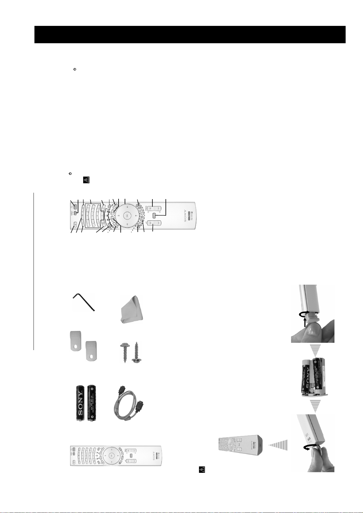
1 Hexagon key
The operating instructions mentioned here are partial abstracts
from the Operating Instruction Manual. The page numbers of
the Operating Instruction Manual remain as in the manual.
2 Brackets
2 Batteries (AAA size)
1 Cleaning cloth
2 Screws
1 PC input cable
Checking the Accessories supplied
Make sure you insert the supplied batteries using the correct polarities.
Always remember to dispose of used batteries in an environmental friendly way.
1 Remote control (RM-906)
Inserting Batteries into the Remote Control
– 7 –
Page 8
KF-50/60SX300
RM-906
ventilation, leave a space of at least 10 cm from the
wall.
Do not block or cover this ventilation opening. For
or
VCR
OUT IN
• Connecting cables are not supplied.
• For more details of VCR connections as well as other connections, please refer to page 24.
Connecting the Aerial and VCR
press this button to switch your VCR or DVD on or off.
using a VCR.
The Scart lead is optional. If you use this optional connection it can improve picture and sound quality when
If you do not use a Scart lead, you will need to manually tune the VCR to a spare channel once the autotune
procedure has been completed. Refer to “Manual Programme Preset” on page 20. Also refer to your VCR
instruction manual to find out how to find the output channel of your VCR.
After setting up, secure the TV set to a wall, etc., using the supplied brackets and screws, for safety purposes.
Stabilizing the TV set
For details. Refer to page 23.
qj NexTView: press this button to display NexTView.
Mount the two supplied brackets with the screws provided to the upper rear side of the TV set.
1
details see page 22.
switched to VCR or DVD, these buttons will operate
Teletext: press this button to switch on Teletext. For
qk
the main functions of your VCR or DVD, once the
ql Operating VCR or DVD: if Media Selector (w;) is
remote control has been programmed. Refer to page
26.
device you want to operate, TV, VCR or DVD. A
w; Media Selector: press this button to select which
screen indication such as channel number, etc. Press
green light will be momentarily lit to show which one
you have selected. For details refer to page 26.
wa Displaying Info: press this button to display all on-
again to cancel.
ws Selecting TV mode: press this button to switch off
PAP (Picture And Picture): press this button to
PAP, Teletext or Video input mode.
divide the screen into two for watching two channels
simultaneously. Refer to page 21.
wd
Pass a strong cord or a chain through each bracket, and then secure to a wall or a pillar, etc.
2
TV sound. Press again to restore the sound.
wf Muting the sound: press this button to mute the
use.
the TV switches automatically into standby mode.
• After 15 minutes without TV signal and without any button being pressed,
• To save energy we recommend switching off completely when TV is not in
lights up). Press again to switch on TV from standby mode.
Press this button to temporarily switch off TV (the standby indicator on the TV
1 TV I/ : To Temporarily Switch Off TV (standby mode):
3
2
1
ws
wd
wf
Overview of Remote Control Buttons
VCR or DVD on/off:
2
5
4
w;
wa
of the source appears on the TV screen. Refer to page 25.
3 Selecting input source: press this button repeatedly until the desired input symbol
6
7
qk
ql
these buttons to select channels. For double-digit programme numbers, enter the
4 Selecting broadcast channels: if Media Selector (w; is switched to TV, press
8
qj
second digit within 2.5 seconds.
9
qh
button to select double-digit channels for Sony's VCR e.g. 23, press -/-- first and next
the buttons 2 and 3.
5 Selecting VCR double-digit: if Media Selector (w;) is switched to VCR, press this
q;
qf
qg
If Media Selector (w;) is switched to VCR, press this button to record programmes.
b) Resetting to factory set levels:
6 a) Recording button:
qa
qd
factory default levels. This will also return the set to the install condition and the
Press, for a minimum of 3 seconds, to return the picture and sound settings to the
qs
“Auto Tuning” menu will appear on the screen. If this is the case refer to the
section “Switching on the TV set and automatically Tuning” (page 11, step 5) of
this manual.
this button to return to the previous channel you were watching (provided you
7 Watching last channel selected: if Media Selector (w;) is switched to TV, press
– 8 –
next press
V
) is switched to
or
v
watched it for at least 5 seconds).
page. Press it again to cancel the freeze.
8 Freezing a teletext page: in teletext mode, press this button to freeze a teletext
qs) is switched on, use these
(w;) is switched to TV and MENU is switched off,
press OK to display a channel overview. If you
9 a) Displaying a channel index: if Media Selector
want to select a channel, press
again the OK button to watch the selected channel.
TV and MENU (
buttons to navigate through the menu system of the
TV. Refer to page 12.
b) Navigator: if Media Selector (w;
press these
buttons to select the next or previous broadcast
repeatedly to change the format of the screen. Refer
to page 16.
qa Selecting broadcast channels:
q; Selecting the screen format: press this button
channel.
qs Menu system: press this button to enter the TV
menu system. Refer to page 12.
qd Adjusting volume: press these buttons to increase
or decrease the audio volume.
repeatedly to change the picture mode. For details on
the different picture modes. Refer to page 13.
qf Selecting picture mode: press this button
Press this button
repeatedly to change the sound effect. For details on
different sound effects. Refer to page 14.
used as Fastext buttons. For details see page 22.
qg Selecting the sound effect:
qh Fastext: In Teletext mode, these buttons can be
Page 9
KF-50/60SX300
RM-906
DVD
OK
Please connect your equipment
according to this chart
After the automatic tuning process has finished and the
optional equipment has been connected at this stage, we
recommend you follow the instructions explained on the
section "Connection Guide" on page 17 to get the optimum
settings related with the optional equipment.
A diagram will appear showing you how to connect a wide range
of equipment to your TV set. Follow the instructions and finally
press the OK button to remove the picture and continue the
automatic process.
4
automatic tuning?
Do you want to start
The Auto Tuning menu appears on the screen. Press the OK
button to select Yes.
5
Yes No
Auto Tuning
Programmes found: 4
button and OK to store the
V
Confirm
No channel found.
Please connect aerial
TVE
TVE2
TV3
01020304050607
Programme Sorting
C33
C27
C58
S02
S06
08
or
v
and do not press any buttons, otherwise automatic tuning
will not be completed.
automatically (ACI system). In this case, the TV
Broadcaster sends a menu in which you can select your city
by pressing the
channels.
message appears automatically on the screen asking you to
connect the aerial. Check the aerial connection (refer to
page 9). Press the OK button to restart the auto tuning
In some countries the TV Broadcaster installs the channels
The TV starts to automatically search and store all
This procedure could take some minutes. Please be patient
6
available broadcast channels for you.
process.
If no channels were found during the auto tune process, a
After all available channels are captured and stored,
the Programme Sorting menu automatically appears
on the screen enabling you to change the order in
7
If you wish to keep the broadcast channels in the tuned order,
If you wish to store the channels in a different order:
go to step 8.
a)
which the channels are stored.
b)
01 TVE
TVE
TVE2
TV3
C33
C27
C58
S02
Programme Sorting
button to select the programme
V
or
v
Press the
number with the channel (TV Broadcast) you wish
1
S06
01020304050607
08
button.
b
button to select the new
V
or
v
Press the
Repeat steps b)1 and b)2 if you wish to change
programme number position for your selected
2
3
channel (TV Broadcast). Press the OK button to store.
to move. Press the
the order of the other channels.
Press the MENU button to remove the menu from the screen
8
Your LCD TV is now ready for use
English
Nederlands
Français
Italiano
Deutsch
Türkçe
Español
Português
Polski
English
Nederlands
Français
Italiano
Deutsch
Türkçe
Español
Português
Polski
Select language
(Set Up menu).
The first time you switch on your TV, a sequence of menu screens appear on the TV enabling you to: 1) choose
However, if you need to change any of these settings at a later date, you can do that by selecting the appropriate
the language of the menu screen 2) Choose the country in which you are going to operate the TV, 3) check how
option in the
to connect optional equipment to your TV, 4) search and store all available channels (TV Broadcast) and 5)
change the order in which the channels (TV Broadcast) appear on the screen.
Language
English
Nederlands
Français
Italiano
Deutsch
Türkçe
Español
Português
Polski
English
Nederlands
Français
Italiano
Deutsch
Türkçe
Español
Português
Polski
Select language
Language
Connect the TV plug to the mains socket (220-240V AC, 50Hz)
The first time that the TV set is connected, it is usually turned on.
The first time you switch on the TV, a Language menu displays
If the TV is off, press the on/off button on the TV set to turn
on the TV.
automatically on the TV screen.
1
English
Nederlands
Français
Italiano
Deutsch
Türkçe
Español
Português
Polski
English
Nederlands
Français
Italiano
Deutsch
Türkçe
Español
Português
selection. From now on all the menus will appear in your chosen
language.
Polski
Select language
Language
buttons on the remote control to select
b
or
B
,
v
,
V
Press the
your language, then press the OK button to confirm your
2
Off
Ireland
Nederland
België/Belgique
Select country
Country
V
or
v
The Country menu appears automatically. Press the
button to select the country in which you are using the TV. Press
the OK button to confirm your selection.
3
Switching On the TV and Automatically Tuning
Luxembourg
France
Italia
Schweiz/Suisse/Svizzera
recommend selecting Russia country if your own country
• If the country in which you want to use the TV set
does not appear in the list.
• To avoid wrong teletext characters for cyrillic languages we
does not appear in the list, select “off” instead of a country.
continued...
– 9 –
Page 10
KF-50/60SX300
RM-906
v
to select the
V
or
v
The “Picture Adjustment” menu allows you to
To do this:
Press the MENU button and then press OK to
alter the picture settings.
Picture Mode: Live
Picture Adjustment
enter this menu. Next press
Contrast:
Reset
desired option and press OK. Finally read below
Noise Reduction: On
how to operate into each option.
OK
Enter:
Select:Back:
Colour Tone: Cool
to select:
V
Personal (for individual settings).
or
you are watching. After selecting this option press OK. Next press repeatedly
Live (for live broadcast programmes, DVD and Digital Set Top Box receivers).
Movie (for films).
Once you have selected your desired option, press OK to store.
,
MENU
Exit:
Picture Mode This option allows you to customise the Picture Mode based on the programme
OK
The Picture Adjustment Menu
Picture Mode: Live
Picture Adjustment
Contrast:
Reset
Noise Reduction: On
Colour Tone: Cool
Select: Enter:
to reduce or enhance picture contrast. Next press OK to store.
b
or
B
"Brightness", "Colour" and "Sharpness" level of "Live" and "Movie" mode are fixed on the
factory to get the best picture quality.
Contrast Press
to darken or brighten the picture. Next press OK to store.
b
or
B
Brightness Press
to decrease or to increase color intensity. Next press OK to store.
b
or
B
Colour Press
to decrease or to increase the green tones. Next press OK to store.
b
or
B
Hue Press
to soften or to sharpen the picture. Next press OK to store.
b
or
B
Sharpness Press
to select Off.
V
or
v
to select: Warm (gives the white colours
V
or
v
. Next press repeatedly
b
press
a red tint), Normal (gives the white colours a neutral tint), Cold (gives the white
Reset Press OK to reset the picture to the factory preset levels.
Colour Tone This option allows you to alter the tint of the picture. After selecting this option
Noise This option is set to On to automatically reduce the snowy picture
Reduction visible in the broadcast signal. To cancel this function, press
colours a blue tint). Next press OK to store.
Lines While viewing an RGB input signal from the PC connector, some picture
to correct it berween -20 and +20.
V
or
v
. Next press repeatedly
b
and press
Finally press OK to store.
mode" is set to "Personal".
• "Brightness" "Colour" and "Sharpness" only appears and only can be altered if "Picture
Correction lines may be not correctly displayed. To correct this problem, select this option
altered: "Contrast", "Brightness" and "Lines Correction".
• "Hue" only appears and only can be altered for NTSC signal (e.g. USA video tapes).
• For an RGB input signal connected to the PC connector, only appear and only can be
PictureAdjustment
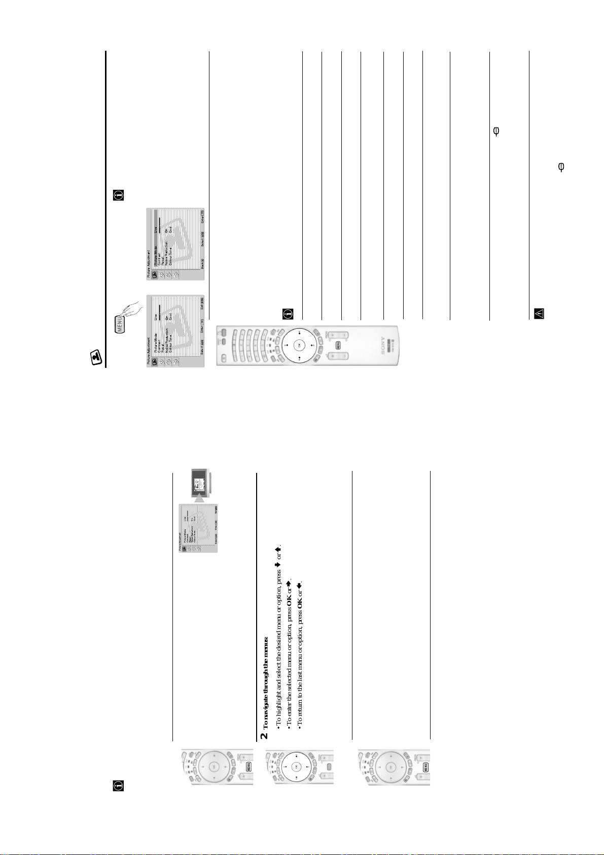
To switch on the menu screens:
1
PictureMode: Live
Contrast:
Reset
NoiseReduction: On
MENU
Exit:
OK
PictureMode: Live
Contrast:
Reset
NoiseReduction: On
ColourTone: Cool
Select: Enter:
PictureAdjustment
MENU
Exit:
OK
ColourTone: Cool
Select: Enter:
Press the MENU button to switch the first level menu on.
.
V
or
v
.
b
To navigate through the menus:
• To highlight and select the desired menu or option, press
• To enter the selected menu or option, press OK or
2
.
b
or
B
/
V
/
.
v
B
• To alter the settings of your selected option, press
• To return to the last menu or option, press OK or
• To confirm and store your selection, press OK.
To switch off the menu screens:
Press the MENU button to remove the menu from the screen.
3
Your LCD TV uses an On-Screen menu system to guide you through the operations. Use the following buttons
on the Remote Control to operate the menu system:
Introducing and Using the Menu System
– 10 –
Page 11
to select:
V
or
v
to select On (the volume level of the channels will stay the same,
V
or
v
independent of the broadcast signal, e.g. in the case of advertisements) or Off (the
volume level changes according to the broadcast signal). Next press OK to store.
If you select “Dolby Virtual” on the “Sound Effect” option, the “Auto Volume” option will
Auto Volume Press
or from an external amplifier connected to the audio outputs on the rear of the TV.
After selecting this option, press OK. Next press repeatedly
automatically be switched to “Off” and vice versa.
On (to listen the TV from the TV set speakers).
TV Speakers This option allows you to select if you want to listen the TV from the TV speakers
time. By using this option, any time the TV is turned
off/on, it returns to the default setting "On").
One time off (to listen to the TV from the external amplifier only one
KF-50/60SX300
RM-906
to select Stereo or Mono
to select Mono (for mono channel if
V
or
v
Dual Sound • For a Stereo broadcast:
Press
V
or
v
Press
available), A (for channel 1) or B (for channel 2).
• For a bilingual broadcast:
21), select Left picture if you want to listen to the left
screen or select Right picture if you want to listen to
the right screen.
PAP Sound Select Frame if you want to listen to
* The “BBE High Definition Sound system” is manufactured by Sony Corporation under
the active screen (framed) of the PAP screen (see page
license from BBE Sound, Inc. It is covered by U.S. Patent No. 4,638,258 and No.
4,482,866. The word “BBE” and BBE Symbol are trademarks of BBE Sound, Inc.
**This TV has been designed to create surround sound effect by simulating the sound of four
are trademarks of Dolby Laboratories.
speakers with two speakers, when the broadcast audio signal is Dolby Surround encoded.
The sound effect can also be improved by connecting a suitable external amplifier (for
details refer to page 25).
**Manufactured under license from Dolby Laboratories. “Dolby” and the double-D symbol
to decrease or increase the volume level
b
or
B
from the headphones.
will appear indicating that the volume you are altering is
%
to select:
V
or
volume Press
v
PAP settings (refer to page 21 for details on PAP).
After selecting this option press OK. Next press repeatedly
Permanent off (to always listen to the TV from external amplifier).
Once you have selected your desired option, press OK to store.
If you have selected "One time off" or "Permanent off", the volume of the external equipment
not the volume of the TV set speakers, it is from the external equipment.
can also be altered by pressing the 2 +/- buttons of the remote control. When the volume
buttons are pressed, the symbol
Headphones Set Up This option allows you to customise the headphones volume and the
to select
v
alter the sound settings.
, then press OK to enter this menu. Next
The “Sound Adjustment” menu allows you to
To do this:
Press the MENU button and press
to select the desired option and
V
or
v
press OK. Finally read below how to operate
into each option.
press
Sound Effect: Dolby Virtual
Treble:
Bass:
Balance:
Reset
Dual Sound: Stereo
Auto Volume: Off
TV Speakers: On
Headphones Set Up
Sound Adjustment
to select:
V
or
v
OK
Enter:
Select:Back:
,
MENU
Exit:
OK
MENU
Exit:
Sound This option allows you to customise the Sound Effect. After selecting this
Effect option press OK. Next press repeatedly
OK
m
The Sound Adjustment Menu
Picture Mode: Live
Contrast:
Reset
Noise Reduction: On
Colour Tone: Cool
Picture Adjustment
Select: Enter:
Sound Effect: Dolby Virtual
Treble:
Bass:
Balance:
Sound Adjustment
Reset
Dual Sound: Stereo
Auto Volume: Off
TV Speakers: On
Headphones Set Up
Select: Enter:
Natural (Enhances clarity, detail and presence of sound by using “BBE High
Off (Flat response).
Definition Sound system”*).
presence of sound for better intelligibility and musical realism).
Dynamic (“BBE High Definition Sound system”* intensifies clarity and
Virtual Logic”).
Once you have selected your desired option, press OK to store.
Dolby** (Dolby Virtual, simulates the sound effect of “Dolby Surround Pro
to select Stereo or Mono. Next press OK to store.
to decrease higher-frequency sounds. Next press OK to store.
to decrease or to increase the lower-frequency sounds. Next press
b
or
B
to emphasise the left or the right speaker. Next press OK to store.
b
or
B
b
or
B
OK to store.
Balance Press
Bass Press
Treble Press
Reset Press OK to reset the sound to the factory preset levels. Next press OK to store.
to select Mono (for mono channel if available), A (for channel 1)
V
V
or
or
v
v
or B (for channel 2). Next press OK to store.
Press
Press
• For a bilingual broadcast:
Dual Sound • For a Stereo broadcast:
continued...
– 11 –
Page 12
KF-50/60SX300
RM-906
to
V
or
B
v
to select "OK" and finally press
S
b
or
B
to select the desired output signal:
V
or
v
S
to chose the equipment you want to connect
V
or
v
to select the equipment chosen (equipment selected also can be deleted
b
). Once you have selected all the equipment to be connected, press
B
to
V
or
v
S
3/ 3 so that you can record from this Scart any signal coming from the TV or from an
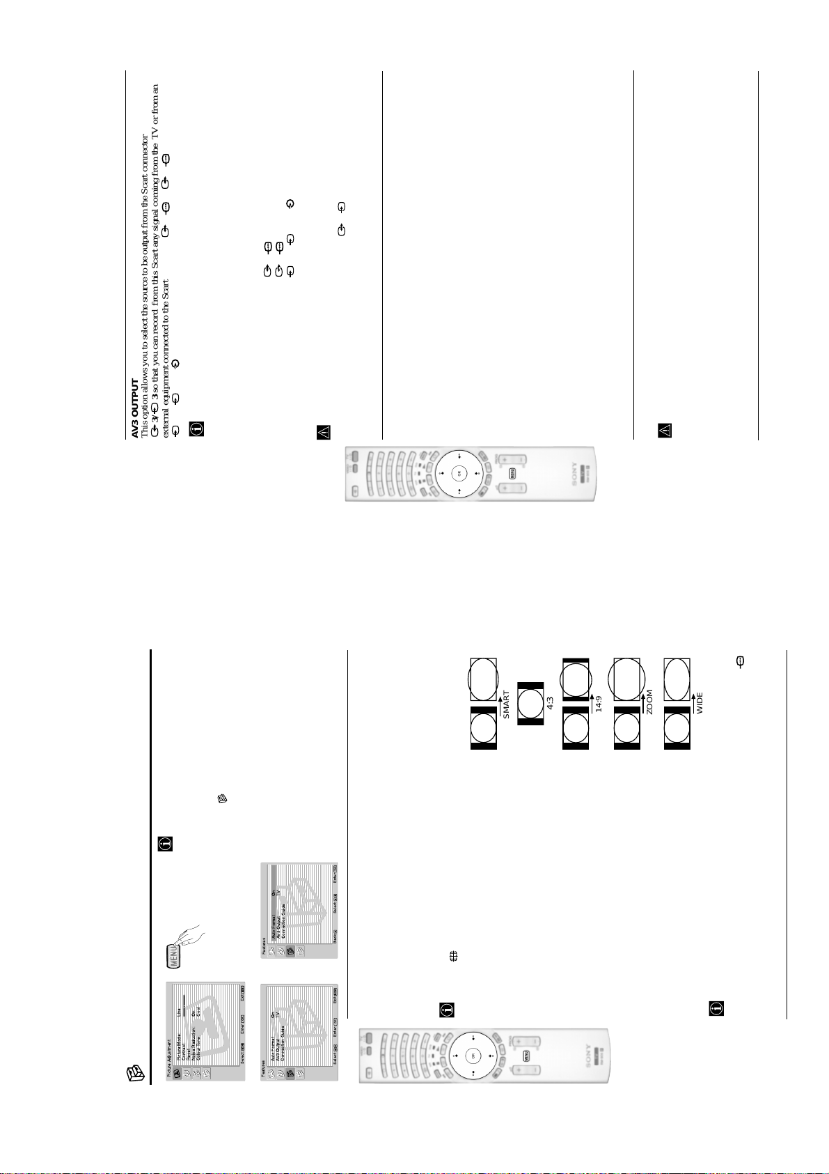
AV3 OUTPUT
This option allows you to select the source to be output from the Scart connector
external equipment connected to the Scart connector 1/ 1, 2/ 2 or front connectors
The “Features” menu allows you to alter vari-
If your VCR supports SmartLink, this procedure is not necessary.
4 or 4 and 4.
S
twice to
v
Press the MENU button and press
To do this:
ous settings of the TV.
TV to output the aerial source.
AV1 to output sources connected to 1/ 1.
To do this:
Once you have entered into the "Features" menu as it is explained in the previous page and after
to select the desired option
V
or
v
select , then press OK to enter this menu.
Next press
AV2 to output sources connected to 2/ 2.
selecting the option, press OK. Then press
and press OK. Finally read below how to
operate into each option.
AV4 to output sources connected to 4 or 4 and 4.
AUTO to output the signal that is being viewed on the TV.
the screen.
Scart, please remember to change back the “AV3 Output” to “TV” for correct
• If you select “AUTO”, the output signal will always be the same one that is displayed on
unscrambling.
• If you have connected a decoder to the Scart 3/ 3 or to a VCR connected to this
CONNECTION GUIDE
to select On (if you wish the TV set to
V
or
v
settings related with the optional equipment.
selecting the option, press OK. Next press
To do this:
1
Even you have already connected the external equipment to the TV set, it is important for you to
follow the instructions of this menu. If you proceed in this way, you will get the optimum picture
among the available: SAT (satellit), Decoder, DVD, GAME, VIDEO or DVD rec. (DVD
Once you have entered the "Features" menu as it is explained in the previous page and after
recorder). Next press
by pressing
select "Confirm" and press OK.
SMART
A new menu will appear showing you on which Scart connector of the rear of the TV should be
connected each equipment. Please connect each equipment according to this information to get
the optimum picture setting of the optional equipment.
2
Once you have connected the optional equipment, press
the OK button of the remote control.
3
4:3
to select «No» and next press the OK button. A new menu appears on the screen in which you
b
can assign the connections according to your preferences.
We strongly recommend you to follow our connection proposals, but in case you do not agree press
or
14:9
This option is only available if an RGB source has been connected to the TV.
RGB CENTRING
This option allows you to readjust the horizontal position of the picture in case you need to do it
when connecting an RGB source.
To do this:
Once you have entered the "Features" menu as it is explained in the previous page and while
watching an RGB source select the “RGB Centring” option and press OK. Then press
adjust the centre of the picture between –5 and +5. Finally press OK to confirm and store.
ZOOM
WIDE
Auto Format On
AV3Output TV
Connection Guide
Features
MENU
Exit:
OK
m
The Features Menu
Picture Mode: Live
Contrast:
Reset
Noise Reduction: On
Colour Tone: Cool
Picture Adjustment
Auto Format On
AV3Output TV
Select: Enter:
Connection Guide
Features
,
OK
Enter: :
Select:Back:
MENU
Exit:
AUTO FORMAT
OK
Select: Enter:
This option allows you to automatically change the aspect ratio of the screen.
To do this:
After selecting the option, press OK. Then press
automatically switch the screen format according to the broadcast signal) or Off (if you wish to
keep your preference). Finally press OK to store.
– 12 –
4/3: Conventional 4:3 picture size, full picture
information.
Even if you have selected “On” or “Off”, you can always modify the format of the screen by
SMART: Imitation of wide screen effect for 4:3 broadcast.
pressing repeatedly on the remote control to select one of the following formats:
14/9: Compromise between 4:3 and 16:9 picture size.
ZOOM: Widescreen format for letterbox movies.
WIDE: For 16:9 broadcast. Full picture information.
to adjust the position of the image on the screen (e.g. to read subtitles).
V
or
v
cut off. Press
connector.
• Only "WIDE" and "4/3" modes can be selected for an RGB signal connected to the PC
• In “SMART”, “ZOOM” and “14/9” modes, parts of the top and bottom of the screen are
mode.
• According to the format of diffussion, black bands can always appear whatever the selected
Page 13
to select the letter, next
b
or
B
,
V
,
v
KF-50/60SX300
RM-906
to
to select
b
or
B
,
V
,
v
to select the desired label and finally press OK.
V
or
v
b
continued...
to alter the input sound level between -9 and
V
or
v
to select the programme number with the channel you wish to name. Next press OK.
V
or
v
Once you have entered the "Set Up" menu as it is explained in the previous page and after selecting the option,
With the first element of the Label column highlighted, press OK and
PROGRAMME LABELS
This option allows you to name a channel using up to five characters (letters or numbers).
press OK, then press
To do this:
1
2
three
v
to select the word “End” on the screen and finally press OK to
b
or
" on the screen to go back and press OK.
B
,
%
V
,
v
• For a blank, select " " on the screen and press OK.
• To correct the letter, select "
When you have finished, press
press OK.
turn off the menu from the screen.
AV PRESET
to select the input source you wish to name: AV1, AV2 or AV3 for the rear
V
or
v
Once you have entered the "Set Up" menu as it is explained in the previous page and after selecting the option,
Scarts, AV4 for front connectors and AV5 for the PC input connector. Next press OK twice.
press OK, then press
To do this:
1
This option allows you to:
a) Designate a name to the external equipment you have connected to the input sockets of the TV set.
" on the screen to go back and press OK.
%
to select the input source you want to alter the input sound level: AV1, AV2 or
V
or
to select the letter, next press OK. When you have finished, press
b
or
B
,
or PC (only for the AV5).
The total predefined labels are: VIDEO, DVD, CABLE, GAME, CAM (camcorder), SAT (satellite)
V
,
a) If you want to use one of the predefined labels, press
A label automatically appears in the label column:
2
v
b) If you want to set a different label, select Edit and press OK. Then, with the first element highlighted, press
• For a blank, select " " on the screen and press OK.
• To correct the letter, select "
the word “End” on the screen and finally press OK to turn off the menu from the screen.
v
press OK, then press
AV3 for the rear Scarts, AV4 for front connectors and AV5 for the PC input connector. Next press twice
+9.
highlight the Sound Offset column. Finally press OK and
Once you have entered the "Set Up" menu as it is explained in the previous page and after selecting the option
To do this:
Change the input sound level of the optional equipment connected.
b)
continued...
to select the desired
V
or
v
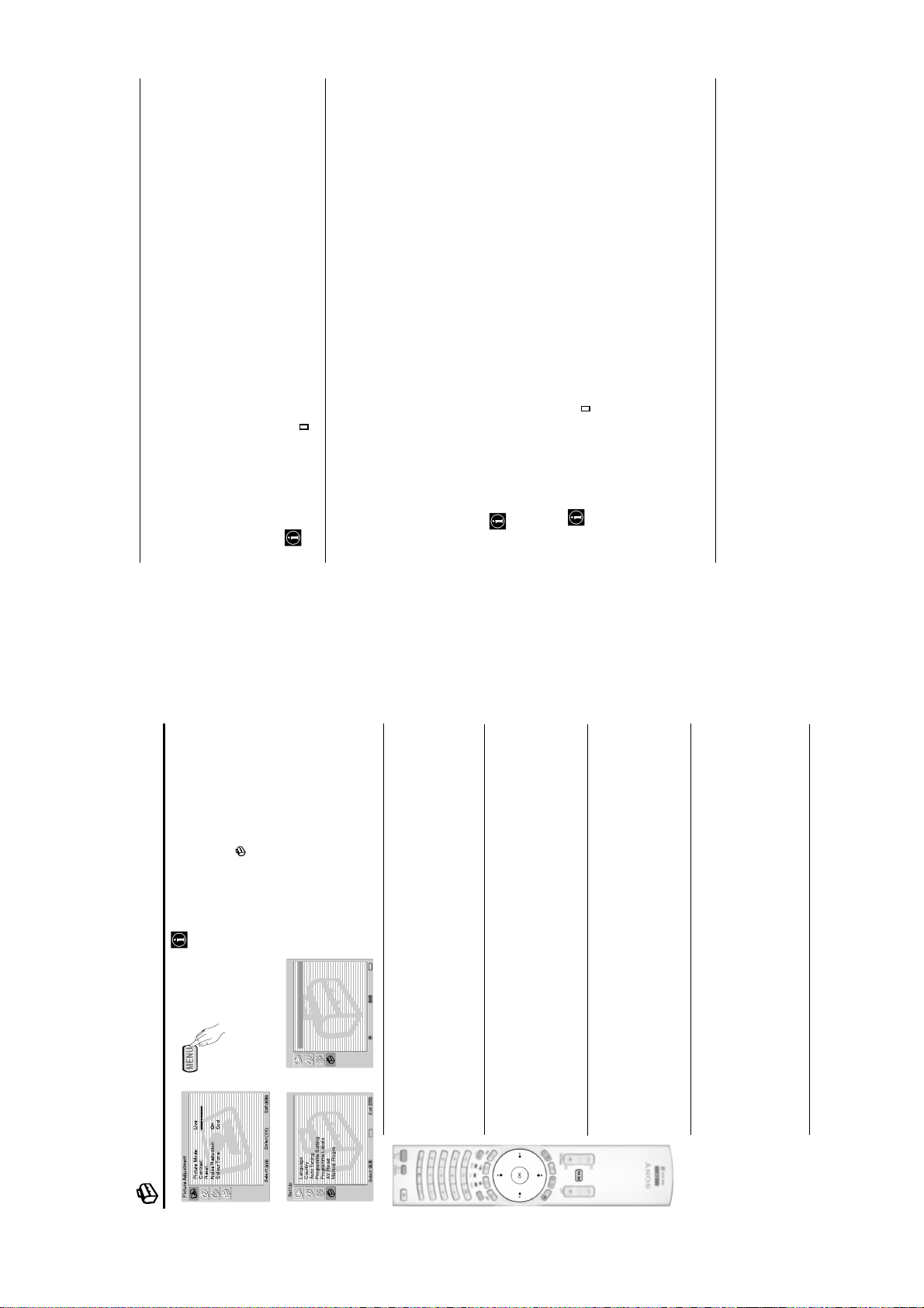
The “Set Up” menu allows you to alter various
options on this TV.
To do this:
option and press OK. Finally read below how
to operate into each option.
times to select , then press OK to enter this
menu. Next press
Press the MENU button and press
Set Up
MENU
Exit:
OK
m
The Set Up Menu
Picture Mode: Live
Contrast:
Reset
Noise Reduction: On
Colour Tone: Cool
Picture Adjustment
Select: Enter:
Set Up
Language
Country
Language
Country
Auto Tuning
Programme Sorting
Programme Labels
AV Preset
,
Auto Tuning
Programme Sorting
Programme Labels
AV Preset
OK
Enter:
Select:Back:
Manual Programme Preset
MENU
LANGUAGE
This option allows you to select the language that menus are displayed in.
To do this:
After selecting the option, press OK and then proceed in the same way as in step 2 of the section
"Switching On the TV and Automatically Tuning" on page 10.
COUNTRY
This option allows you to select the country in which you wish to operate the TV set.
To do this:
After selecting the option, press OK and then proceed in the same way as in step 3 of the section
"Switching On the TV and Automatically Tuning" on page 10.
AUTO TUNING
This option allows you to automatically search for and store all available TV channels.
To do this:
After selecting the option, press OK and then proceed in the same way as in the steps 5 and 6 of
the section “Switching On the TV and Automatically Tuning” on page 11.
PROGRAMME SORTING
This option allows you to change the order in which the channels (TV Broadcast) appear on the
screen.
To do this:
After selecting the option, press OK and then proceed in the same way as in the step 7 of the section
OK
Enter:
Manual Programme Preset
Select: Exit:
“Switching On the TV and Automatically Tuning” on page 11.
– 13 –
Page 14
KF-50/60SX300
RM-906
Navegador
Aceptar Versión
Configuracióndel Sistema
MoveFrame
PROG+ PROG-
03
Select: Select:
buttons.
b
or
B
the active screen. It means that when you want to select
the PAP source, you will be doing it in the active screen.
On the screen appears a banner guiding you how to operate
PAP. This banner will disappear after some seconds but it
always can be displayed again by pressing the button.
Press to display PAP.
One of the screens will be framed to indicate that this is
Switching PAP on and off
1
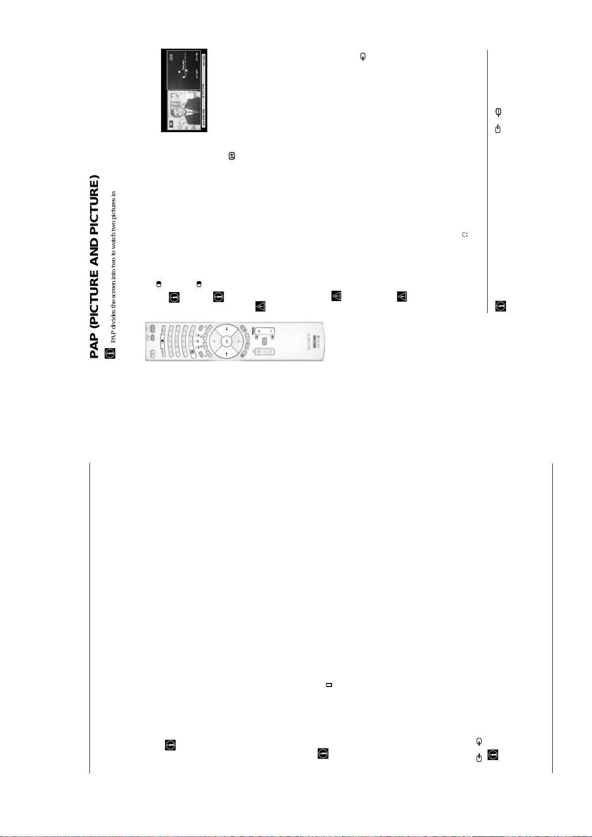
PAP divides the screen into two to watch two pictures in format 4:3 simultaneously.
Press again to remove PAP.
2
This is only possible if Media Selector is set to TV.
Changing the active screen
PAP (PICTURE AND PICTURE)
to select the channel tuning ("C"
V
or
v
to select the TV Broadcast system (B/G
V
or
v
.
B
button to select the left screen as the active screen. Next press the number buttons
B
or PROG +/- to select a TV channel.
Selecting a TV channel:
Selecting PAP source
,
v
Press the
1
to select the word
b
or
B
,
V
,
v
" on the screen to go back and press OK.
To change the active screen (framed), press the
Video input signals can not be displayed on the left screen.
button to select the right screen as the active screen. Next press repeatedly the
b
Press the
Selecting an input source:
2
%
button to watch the input signal of a connected equipment onto the TV right screen. For more
details on which input symbol you want to choose, please see section "Viewing pictures from
equipment connected to the TV" on page 25.
RF signal (TV broadcast channels) can not be displayed on the right screen.
Selecting the sound
The sound of the active screen (framed) always comes from the TV set loudspeakers.
Besides that, you can listen to the active screen as well as the non active screen via headphones.
To do this:
With the PAP switched on, refer to the section "The Sound Adjustment Menu", select "Headphones
Then select the AFT
.
OK
to select On. Finally press OK twice to confirm and store.
V
or
v
to adjust the fine tuning between -15 and +15. Finally press OK twice
V
or
v
. Next press
b
In PAP (picture and picture) mode, the output from the Scart 2/ 2 is fixed to the right
picture.
Set Up" and set the option " PAP Sound" according your preference. For details see page 15.
to select On. Finally
V
or
v
. Next press
b
to select which programme number you want to preset the channel on (for VCR, select
V
or
v
Press
Programme Preset" option, press OK. Next with Programme option highlighted press OK.
To do this:
1 Once you have entered the “Set Up”menu as it is explained on page 18 and after selecting the "Manual
MANUAL PROGRAMME PRESET
This option allows you to:
a) Preset channels or the VCR channel one by one to the programme order of your choice.
The following option is only available depending on the country you have selected in the “Country”
programme number “0”). Then press
2
. Next press
b
as it is explained on page 18 and after selecting the "Manual Programme" option, press
option and press
To do this:
While watching the channel (TV Broadcast) you wish to fine tune, and once you have entered the “Set Up” menu
to store.
To do this:
Once you have entered the "Set Up" menu as it is explained on page 18 and after selecting the "Manual
d) Skip any unwanted programme numbers when they are selected with the PROG +/- buttons.
This option is only available depending on the country you have selected in the “Country” menu.
S
Programme Preset" option, press OK. Next with the Programme option highlighted, press the PROG +/- button
to select the programme number you want to skip. When the programme you want to skip appears on the screen,
select the Skip option and press
To cancel this function afterwards, select “Off” instead of “On” in the step above.
View and record scrambled channels (e.g. from a pay TV decoder) when using a decoder connected to Scart
3/ 3 directly or through a VCR.
e)
Preset" option, press OK. Next select the Decoder option and press
To do this:
Once you have entered the "Set Up" menu as it is explained on page 18 and after selecting the "Manual Programme
press OK twice to confirm and store.
To cancel this function afterwards, select "Off" instead of "On" in the step above.
After selecting the Channel Number option, press OK. Next press
3
to search for it. When you have tuned the desired channel, press OK twice to store.
V
or
v
and
b
for terrestrial channels or "S" for cable channels). Then press the number buttons to enter directly the channel
number of the TV Broadcast or the channel of the VCR signal. If you do not know the channel number, press
Repeat all the above steps to tune and store more channels.
b) Label a channel using up to five characters.
to select the letter, next press OK. When you have finished, press
b
• To correct the letter, select "
• For a blank, select " " on the screen and press OK.
or
B
To do this:
,
Once you have entered the “Set Up”menu as it is explained on page 18 and after selecting the "Manual
V
Programme Preset" option, press OK. Next with the Programme option, highlighted press the PROG +/- button
“End” on the screen and finally press OK to turn off the menu from the screen.
to select the programme number with the channel you wish to name. When the programme you want to name
appears on the screen, select the Label option and press OK. Then, with the first element highlighted, press
however you can manually fine tune the TV to obtain a better picture reception in case the picture is distorted.
c) Fine tune the broadcast reception. Normally the automatic fine tuning (AFT) will give the best possible picture,
.
B
menu.
After selecting the System option, press OK. Then press
Then press
for western European countries, D/K for eastern European countries, L for France or I for United Kingdom).
– 14 –
Page 15
KF-50/60SX300
RM-906
different broadcasters.
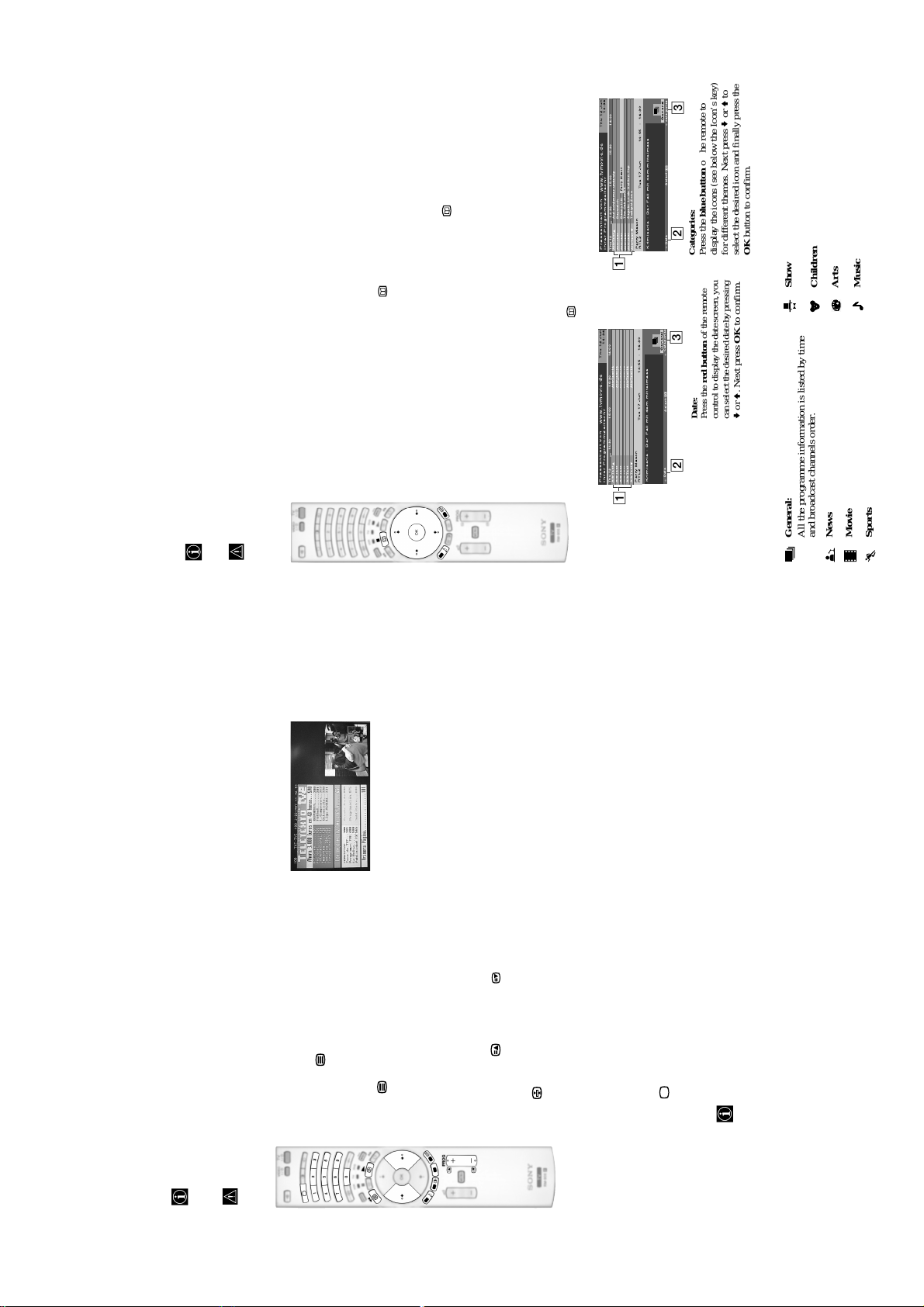
When looking for information you can search by theme (sports, art, etc...) or date.
If wrong characters appear when viewing NexTView, use the menu system to enter the “Language” menu (see
NexTView is an on-screen electronic programme guide, providing you with programme information for
NexTView*
*(depending on availability of service).
page 18) and select the same language as the NexTView is broadcasted.
Displaying NexTView
Select a broadcast channel providing a NexTView service. In this case the indication
“NexTView” is displayed as soon as data is available.
1
a) “Programme List” interface:
To see NexTView service you have two different types of NexTView interface. These depend
on the % of available data:
2
displayed on the screen, press the button on the remote control to watch the
“Programme List” interface (see fig. 1).
Whilst you are watching TV, and after the indication “NexTView” (coloured white) is
b) “Overview” interface:
14:36
Thu12 Jun
15:30 16:00
15:00
Perry Mason
www.tvmovie.de
14:30
Aufschlimmer undewig
Baywatch
BennyHill
IhrerProgrammzeitschr
Praesentiertvon
Thu12
AttrText
AttrText
AttrText
1
TheOsbournes
AttrText
Segeln:Louis Vuitton Cup
TwilightZone
AttrText
AttrText
3
General
categories
Select:
Tue17 Jun 14:55 - 16:30
2
Date
Krimiserie- Der Fall mit dem mittelmass
PerryMason
RTL2
display the icons (see below the Icon’s key)
for different themes. Next press v or V to
Categories:
Press the blue button of the remote to
select the desired icon and finally press the
OK button to confirm.
3
14:36
16:00
Thu12 Jun
15:30
AttrText16
AttrText16
AttrText16
AttrText16
AttrText16
15:00
www.tvmovie.de
14:30
IhrerProgrammzeitschr
Praesentiertvon
Thu12
AttrText
AttrText
AttrText
AttrText16
AttrText
AttrText
AttrText
to move downwards or upwards.
to move left or right.
V
b
or
or
v
to watch the “Overview” interface (see fig. 2).
B
• Press
To navigate through NexTView:
3
selected programme.
•Press
To switch NexTView off, press the button on the remote control.
• Press OK to confirm a selection.
• If you have selected a programme, press OK to get more information on the
4
(100% data may not be available depending on the area) the indication “NexTView”
(coloured black) is displayed on the screen. Press the button on the remote control
Whilst you are watching TV, and after more than 50% of NexTView data is available
3
General
CategoriesDate
Select:
Date:
Press the red button of the remote
control to display the date screen, you
can select the desired date by pressing
Tue17 Jun 14:55 - 16:30
v or V. Next press OK to confirm.
2
2
Krimiserie- Der Fall mit dem mittelmass
PerryMason
RTL2
1
“Programme List” interface (fig. 1): “Overview” interface (fig. 2):
Programmme list
1
Icons’ key:
Show
General:
All the programme information is listed by time
Music
Children
Arts
and broadcast channels order.
News
Movie
Sports
(usually page 100) gives you information on how to use the service. To operate teletext, use the remote control
buttons as indicated below.
Teletext is an information service transmitted by most TV stations. The index page of the teletext service
Teletext errors may occur if you use a channel (TV Broadcast) with a weak signal.
Teletext
Select the broadcast channel which carries the teletext
service you wish to view.
1
To switch on Teletext :
Press the button one time to enter Picture and
Text (P&T) mode. The screen is divided into two with
2
the Text display on the left and the TV channel in the
right corner.3If you wish to view the Text in full screen mode, press
the button a second time.
To select a Teletext page:
is not available. If this is the case, input another page number.
Input 3 digits for the page number, using the numbered buttons.
• If you make a mistake, retype the correct page number.
• If the counter on the screen continues searching, it is because the page
To access the next or preceding page:
Press PROG + ( ) or PROG - ( ) .
To freeze a teletext page:
A teletext page may consist of several sub pages. In this case, one or more arrows appear next
to the page number and an information box is displayed at the bottom of the screen showing the
number of sub pages contained on this page. As soon as sub pages are available, they start to
Press . Press it again to cancel the freeze.
To select a sub page:
automatically run. If you want to stop the show and select your desired sub page, press repeatedly
– 15 –
.
b
or
B
To Switch Off Teletext:
Press .
the bottom of the teletext page. Press the appropriate coloured button (red, green, yellow
Fastext service lets you access Teletext pages with one button push.
When you are in Teletext mode and Fastext is broadcast, a colour coded menu appears at
Fastext
or blue) to access the page corresponding to your menu choice.
Page 16
KF-50/60SX300
RM-906
S
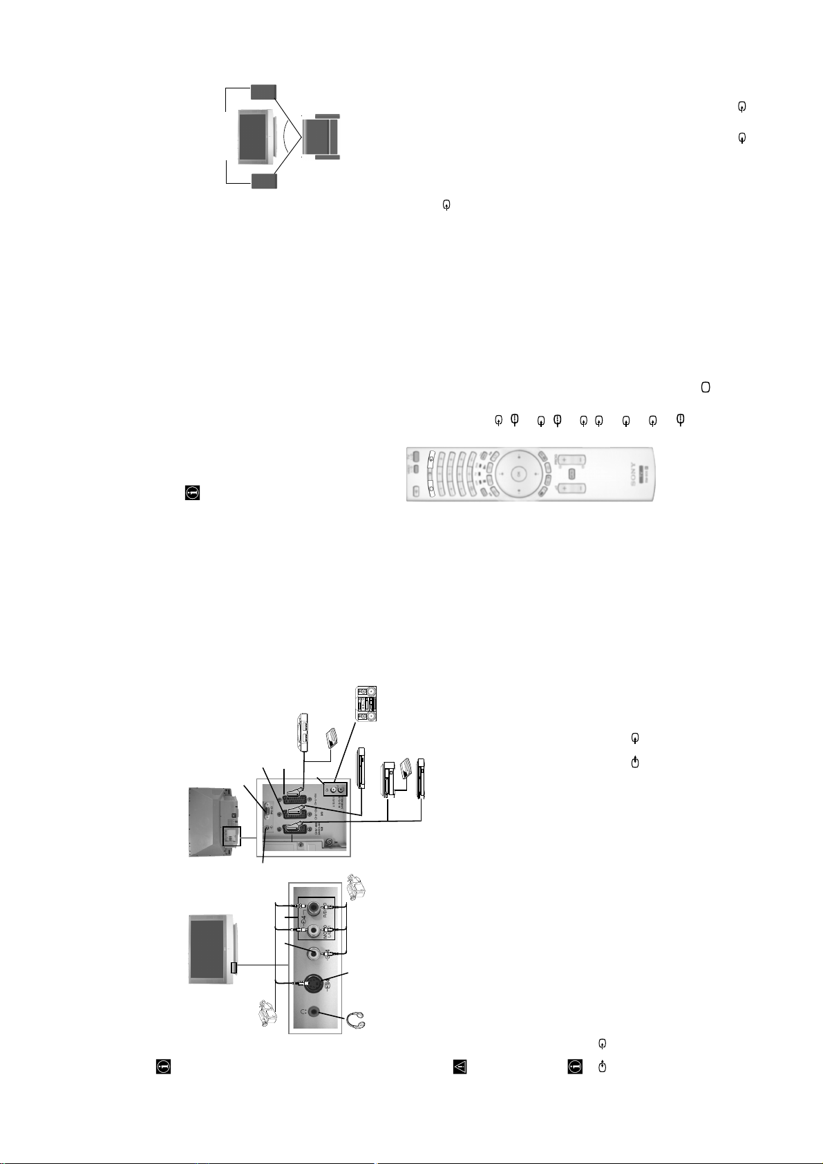
Connecting Audio Equipment to the TV
Conect your audio equipment to the audio output sockets D if you wish to amplify the audio output from TV. Next
, using the menu system, select the “Sound Adjustment” menu and set the “TV Speakers” to “One time off” or
Hi-Fi speakers
The volume of the external speakers can be altered by pressing the volume buttons on the remote control. The
Treble and Bass settings can also be altered through the “Sound Adjustment” menu (see page 14).
"Permanent off" (see page 15).
To enjoy “Dolby Virtual” sound effect through your
audio equipment
Place the speakers of your equipment in front of your listening position and
beside the TV set, keeping a distance of 50 cm between each speaker and the
~50°
TV set.
Then by using the menu system, select the menu “Sound Adjustment”. Next
Your sitting position
select “Dolby Virtual” on the “Sound Effect” option (see page 14).
RGB source has been connected.
Connect your equipment to the designated TV socket, as indicated in the previous page.2Switch on the connected equipment.3To watch the picture of the connected equipment, press the button repeatedly until the correct
1
Viewing pictures from equipment connected to the
TV
input symbol appears on the screen.
Symbol Input Signals
1 • Audio / video input signal through the Scart connector G
1 • RGB input signal through the Scart connector G. This symbol appears only if an
2 • RGB input signal through the Scart connector F. This symbol appears only if an
2 • Audio / video input signal through the Scart connector F.
RGB source has been connected.
an S Video source has been connected.
3 • S Video Input signal through the Scart connector E. This symbol appears only if
3 • Audio/video input signal through the Scart connector E.
S
C.
4 • S Video Input signal through the front S Video input jack A and Audio signal
4 • Video input signal through the phono socket B and Audio input signal through
S
through C. This symbol appears only if an S Video source has been connected.
5 • RGB input signal through the PC connector H and I.
Press the button on the remote control to return to the normal TV picture.
4
For Mono Equipment
Connect the phono plug to the L/G/S/I socket on the front of the TV and select 4 or 4 input
signal using the instructions above. Next, refer to the “Sound Adjustment” section of this manual and
set “Dual Sound” option to “A” on the sound menu screen (see page 14).
Hi-fi
VCR
DVD
8mm/Hi8/
DVC
camcorder
A
• Using the following instructions you can connect a wide range of optional equipment to your TV set.
• Connecting cables are not supplied.
Decoder/
Set Top Box
Computer
product of Sony
Entertainment, Inc.
“PlayStation” is a
*
trademark of Sony
“PlayStation” is a
*
H
S VHS/Hi8/
DVC
camcorder
2
Computer
Entertainment, Inc.
F
I
“PlayStation”*
1
G
D
E
C
B
Connecting Equipment to the TV
Decoder/ Set Top Box
DVD recorder
continued...
S
same time.
• To avoid picture distortion, do not connect external equipment to connectors A and B at the
• Do not connect a Decoder to the Scart F.
Connecting a VCR
To connect a VCR, please refer to the section “Connecting the aerial and VCR” of this instruction manual on page 9.
Connecting a VCR that supports SmartLink
S
SmartLink is a direct link between the TV set and the VCR. For more information on SmartLink, please refer
to the instruction manual of your VCR.
3/ 3 E.
VCR connected to this Scart
If you have connected a decoder or a Set Top Box to the Scart 3/ 3 E or through a
Select the “Manual Programme Preset” option in the “Set Up” menu and after entering in the “Decoder**” option,
select “On” (refer to page 20). Repeat this option for each scrambled signal.
If you use a VCR that supports SmartLink, please connect the VCR to the TV using a Scart lead to the Scart
**This option is only available depending on the country you have selected in the “Country” menu.
– 16 –
Page 17
KF-50/60SX300
RM-906
e
r
e
r
o
o
m
m
d
d
n
n
a
a
m
m
8
.
2
.
1
2
:
:
K
K
0
0
0
0
3
3
X
X
S
S
0
0
5
-
6
-
F
F
K
K
(Optimum viewing position)
e
r
e
r
o
65º
65º
o
m
m
d
d
n
n
a
a
m
m
8
.
2
.
1
2
:
:
K
K
0
0
0
0
3
3
X
X
S
S
0
0
5
-
6
-
F
F
K
K
30º
30º
(Optimum viewing position)
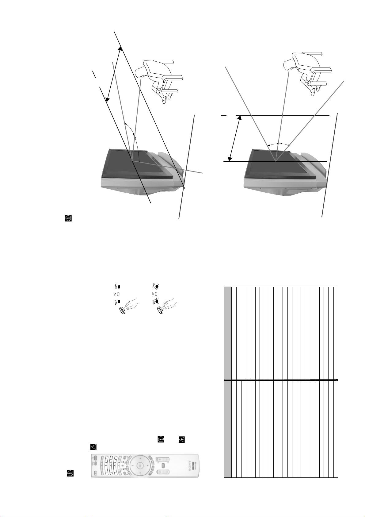
For the best picture quality, try to position the TV set so that you can view the screen from within the areas
shown below.
Optimum Viewing Area
Horizontal viewing area
fig. 1
fig. 2
6 sec.
Vertical viewing area
041, 042, 043, 044, 053, 054, 055
SONY 001, 029, 030, 036, 037, 038, 039, 040,
AIWA 021
AKAI 032
DENON 018, 027, 020, 002
GRUNDIG 009, 028, 023, 024, 016, 003
HITACHI 025, 026, 015, 004, 035
JVC 006, 017
KENWOOD 008
LG 015, 014, 034
LOEWE 009, 028, 023, 024, 016, 003
MATSUI 013, 016
ONKYO 022, 033
PANASONIC 018, 027, 020, 002, 045, 046, 047
PHILIPS 009, 028, 023, 024, 016, 003, 031
PIONEER 004, 050, 051, 052
SAMSUNG 011, 014
SANYO 007
SHARP 019, 027
THOMSON 012
TOSHIBA 003, 048, 049
YAMAHA 018, 027, 020, 002
work please check that you entered the correct code set or try
the next code listed against the brand.
• If your device is not working or some of the functions do not
• Not all brands are covered and not all models of every brand may be covered.
Turn on your VCR or DVD and check that the main functions work.
4
Always remember to press Media Selector button until the green light iluminates according to
the equipment you want to operate with this remote control: VCR, TV or DVD.
5
On those brands that have more than one code, enter the first code number.
• Before you start, look up the 3 digit code for your brand of DVD or VCR from the list below.
To do this:
In it’s default condition this remote control will operate the basic functions of this Sony TV, Sony DVDs and
most Sony VCRs. To control VCRs and DVDs of other manufacturers (and some Sony VCR models), the
remote control needs to be configured.
fig. 3
• A small label is added inside the battery door to allow you to record your brand codes.
Press the Media Selector button until the required green light (VCR or
DVD) is lit (see fig. 1).
1
Before the green light goes out, press and hold the yellow button for
2
While the VCR and DVD lights are flashing, enter all three digits of the
buttons on the remote control (see fig. 3).
approximately 6 seconds until the green light (VCR or DVD) starts
code for your brand of VCR or DVD (see the list below) using the number
flashing (see fig. 2.).
3
If your selected code is entered correctly, the three green lights will
be lit momentarily. Otherwise repeat all the above steps.
Remote Control Configuration for VCR or DVD
– 17 –
VCR Brand List DVD Brand List
Brand Code Brand Code
SONY (VHS) 301, 302, 303, 308, 309,362
SONY (BETA) 303, 307, 310
SONY (DV) 304, 305, 306
AIWA 325, 331, 351
AKAI 326, 329, 330
DAEWOO 342, 343
GRUNDIG 358, 355, 360, 361, 320, 351, 366
HITACHI 327, 333, 334
JVC 314, 315, 322, 344, 352, 353, 354, 348, 349
LG 332, 338
363, 364
LOEWE 358, 355, 360, 361, 320, 351
MATSUI 356, 357
ORION 328
PANASONIC 321, 323
PHILIPS 311, 312, 313, 316, 317, 318, 358, 359,
SAMSUNG 339, 340, 341, 345
SANYO 335, 336
SHARP 324
THOMSON 319, 350, 365
TOSHIBA 337
Page 18
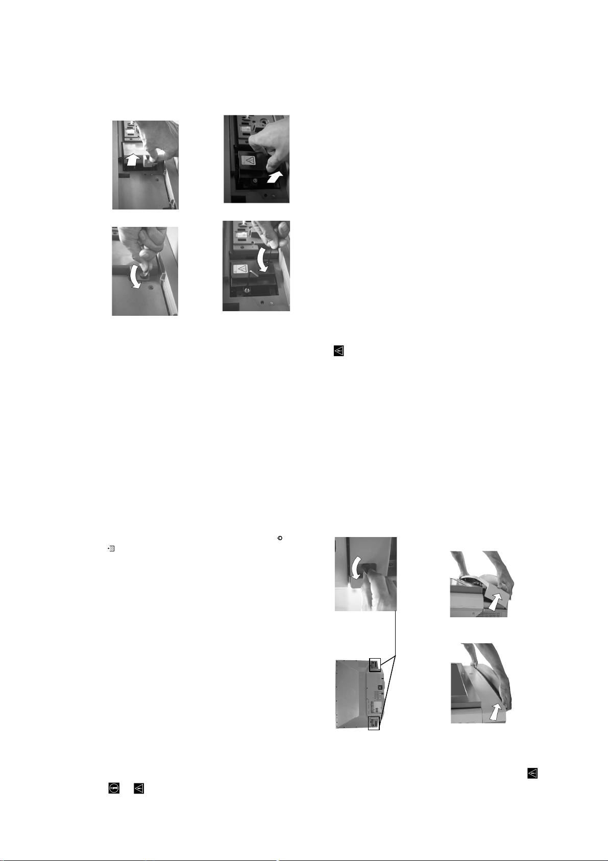
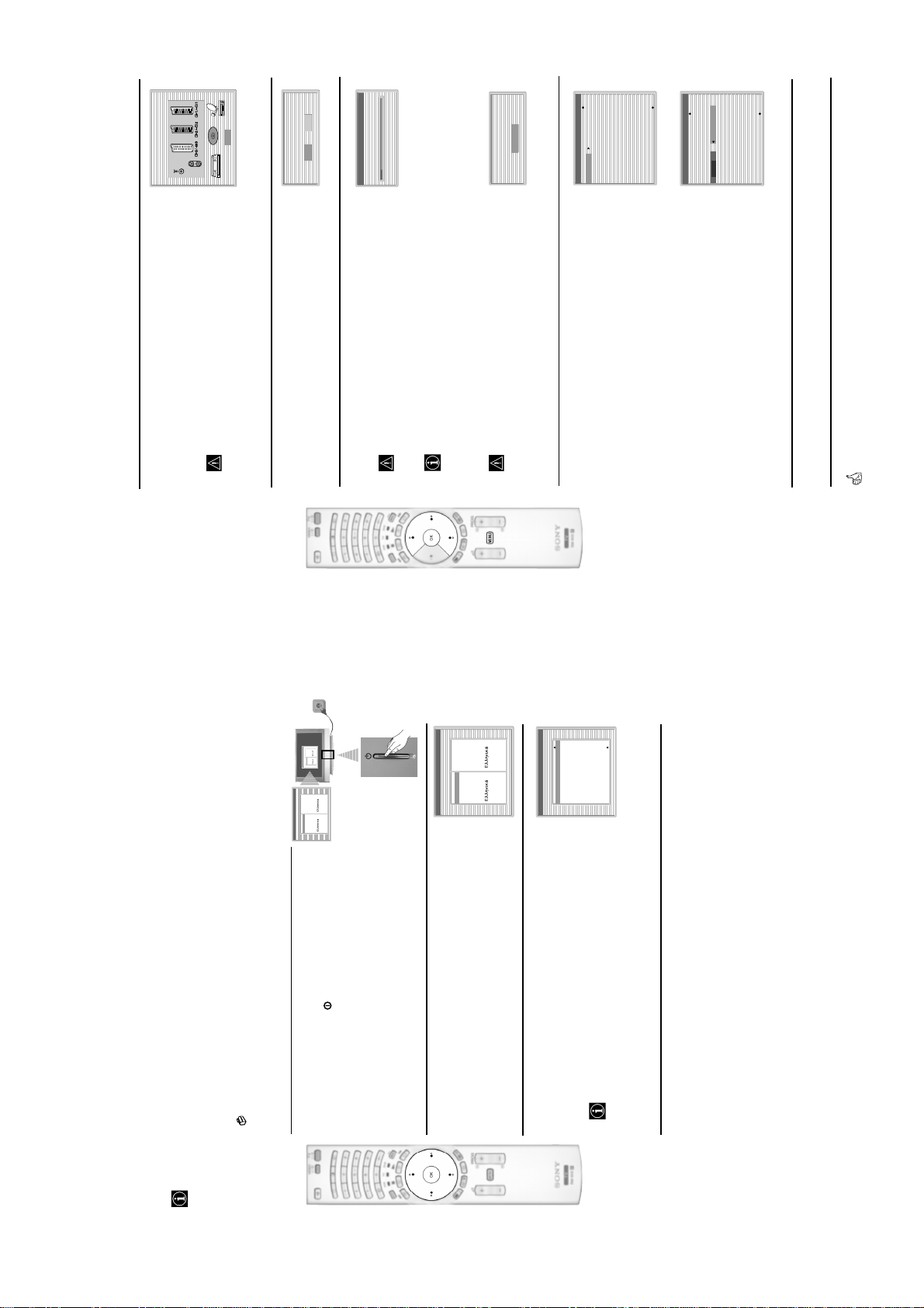
Loosen two screws with the Pull out the lamp by the handle.
hexagon key supplied.
KF-50/60SX300
RM-906
The lamp is still extremely hot immediately after the power is turned off. Be careful that you don’t touch the
front glass or surrounding area of the lamp or the glass of the lamp compartment.
Loosen the screw with an object such as a coin and remove the lamp cover.
4
Loosen the two screws and pull out the lamp.
5
on the TV set flashes.
Attach the new lamp.
6
Replace the new lamp securely in the lamp receptacle and fasten the screws tightly using the hexagon key supplied.7Attach the lamp cover.
Fasten the screw tightly with an object such as a coin.8Attach the front panel.
Attach the front panel by pushing left and right side into place. Next, fast again the two screws plaeed on the left and
right corner of the rear of the TV.
• Only use the lamp XL-2100E for replacement. If you use another lamp, it may cause damage to the TV set.
When the lamp becomes dark or the picture colour is not normal or the lamp indicator on the TV set flashes,
• Do not remove the lamp except when replacing it.
replace with a new lamp.
after the power has been turned off for 30 minutes.
• Before replacing the lamp, turn off the power and disconnect the power cord.
• Replace the lamp only after it becomes cool. The front glass of the lamp remains at least 100 °C (212 °F) even
the lamp compartment, as you may be burned.
• Do not place the old lamp in proximity to children or flammable material.
• Do not get the old lamp wet, or insert objects inside the lamp. It may cause the lamp to explode.
• Do not place the old lamp near easily flammable objects, as this may cause fire. Also, do not put your hand inside
• Attach the new lamp securely. If it is not securely attached, the picture may become dark.
Replacing the lamp
dirty, the picture quality may deteriorate or the lamp life may shorten.
• Attach the lamp cover firmly. If it is not firmly attached, the power will not turn on.
• When the lamp burns out, a noise is audible. This does not indicate damage to the TV set.
• Consult your nearest Sony service center to obtain a new lamp.
• Do not touch or stain the front glass of the new lamp or the glass of the lamp compartment. If the glass become
• Always remember to dispose of used lamps in an evironmentally friendly way.
Disconnect the power cord to continue changing the lamp.
• If you start changing the lamp without disconnecting the power cord, the standby indicator
Turn off the power and disconnect the power cord.
1
• Replace the lamp 30 minutes or more after the power is turned off to allow it to cool.
• Prepare the new lamp.
– 18 –
your fingernails.
Grasp the left and right side of the front panel with your fingers and pull it forward. Be careful not to catch
Remove the front panel.
Loosen the two screws placed on the left and right corner of the rear of the TV with an object such as a coin.
2
Remove the front panel without moving the TV set
3
Page 19
KF-50/60SX300
RM-906
(dots x lines) frequency frequency
PC Input Specifications
PC Input Timing
Input signal frequency:
Horizontal: 31,4 - 48,4 KHz.
Vertical: 59 - 61 Hz.
Power Consumption:
Maximum Resolution: 1024 dots x -768 lines.
1 W
210 W
Standby Power Consumption:
≤
Dimensions (w x h x d) :
Preset mode timing table for PC
Nº Resolution Graphic mode Horizontal Vertical
approx. 1376 x 923 x 442 mm.
approx. 1618 x 1062 x 542 mm.
• KF-50SX300K:
• KF-60SX300K:
Weight:
• KF-50SX300K:
(kHz) (Hz)
approx. 37.5 kg.
approx. 48.5 kg.
• KF-60SX300K:
1 640 x 480 VESA 60 31.469 59.940
2 800 x 600 VESA 60 37.879 60.317
AAA size).
Accessories supplied:
• 1 Remote Control (RM-906)
• 2 Batteries (IEC designated,
3 1024 x 768 VESA 60 48.363 60.004
• 1 PC input cable.
• 1 Hexagon key.
• 2 Brackets.
• 2 Screews.
Other features:
resolution).
• Digital Comb Filter (High
• Teletext, Fastext, TOPtext.
• 1 Cleaning Cloth.
•NexTView.
•SmartLink.
• TV system autodetection.
• Dolby Virtual.
• BBE Digital.
•NICAM.
•PAP.
• ACI (Auto Channel
Installation).
• Auto Format.
Optional accessories:
these sets (SU-5060SX3).
• Stand especially designed for
1/ 1
21-pin scart connector
(CENELEC standard)
B/G/H, D/K, L, I
RGB input, TV audio/video
including audio/video input,
Colour system:
PAL
Rear Terminals
• AV1
TV system:
Depending on your country
Technical Specifications
selection:
output.
SECAM, NTSC 3.58, 4.43 (only
Video In)
• AV2
2/ 2
21-pin Scart connector
(CENELEC standard)
including audio / video input,
Channel Coverage:
VHF: E2-E12
UHF: E21-E69
CATV: S1-S20
RGB input, monitor audio/video
output.
HYPER: S21-S41
D/K: R1-R12, R21-R69
L: F2-F10, B-Q, F21-F69
S
21-pin Scart connector
(CENELEC standard)
• AV3
3/3
I: UHF B21-B69
Panel System:
LCD (Liquid Crystal Display)
including audio / video input, S
video input, selectable audio /
video output and SmartLink
panel.
Projected picture size:
- phono jacks
interface.
• audio outputs (Left/Right)
127 cm measured diagonally).
153 cm measured diagonally).
• KF-50SX300K: 50 inches (approx.
• KF-60SX300K: 60 inches (approx.
– 19 –
• PC audio input - minijack.
• PC PC input.
DIN
jack
S
Front Terminals
• 4 S Video input – 4 pin
• 4 video input – phono
jacks
• 4 audio input – phono
2 x 20 W (music power)
• headphones jack
Sound Output:
2 x 10 W (RMS)
Woofer:
30 W (music power)
15 W (RMS)
Ecological Paper - Totally Chlorine Free
This instruction manual has been printed on:
Design and specifications are subject to change without notice.
Page 20
KF-50/60SX300
RM-906
Selector is set to TV.
Solution
• PAP navigation is only possible in TV mode, please check that Media
buttons do not work
b
and
B
,
V
,
Problem
v
in PAP mode.
• Be sure you are ponting it towards the remote control receiver (see page 8).
Remote control does not function.
you are using (VCR, TV or DVD).
Media Selector has been set correctly. Enter the necessary code set as
• Check that the Media Selector on the remote control is set to the device
explained on page 26.
• If the remote control does not operate the VCR or DVD even when the
• Replace the batteries.
• Contact your nearest Sony service centre.
The standby indicator on the TV
flashes.
replace the internal lamp. For details refer to pages 28 and 29.
• Turn the TV off. Turn the TV on again, if the lamp indicator is still lit then
on front of the
TV set is lit.
The lamp indicator
firmly seated in their sockets.
Solution
Problem
Personal Computer
in.
• Check that the video signal cable is properly connected and all plugs are
• Check that the 15-Dsub video input connector’s pins are not bent or pushed
Personal Computer output format
If no picture is displayed and the NO
SYNC message appears on the
screen.
corresponding format for the television. In case it is not, adjust the
resolution and refresh rate to the corresponding signal (refer to page 31).
• Check that the output signal format of the Personal computer is set to the
computer keyboard.
Problems caused by the connected computer
• The computer is in power saving mode. Try pressing any key on the
• Check that the computer’s power is "on".
• Check that the computer’s keyboard is properly connected.
output, and the signal is correctly output to the television.
• Check that the graphic board is completely seated in the proper bus slot.
• In case of a notebook PC, check that the monitor signal is set to the external
the "Lines Correction" option between -20 and +20 (see page 13).
• Using the menu system, select the "Picture Adjustment" menu and adjust
Some picture lines are not correctly
displayed.
this case, increase the size of the fonts and/or reduce the mesh pattern
brightness.
due to the output format of the image. These screens can be displayed on
• Small letters, check or mesh patterns cannot be accurately displayed. In
Blurred letters or vertical lines or
shade or noise is visible in detailed
patterns.
the monitor of the Personal Computer.
• Depending on the PC, the Startup or Setting screens may not be displayed
The Startup or the Setting screens of
the Personal Computer cannot be
displayed.
• If you continue to experience problems, have your TV serviced by qualified personnel.
• Never open the casing yourself.
Solution
• Check the aerial connection.
• Plug the TV in and press the button on the front of the TV.
• If the standby indicator is on, press TV button on
the remote control.
Here are some simple solutions to problems which may affect the picture and sound.
Problem
No picture (screen is dark) and no
Troubleshooting
TV
sound.
“Reset” to return to the factory settings (see page 13).
• Using the menu system, select the “Picture Adjustment” menu and select
• Check that the optional equipment is on and press the button
repeatedly on the remote control until the correct input symbol is
displayed on the screen (see page 25).
• Press the + button on the remote control.
Poor or no picture (screen is dark), but
good sound.
No picture or no menu information
from equipment connected to the
Scart connector.
Good picture, no sound.
menu (see page 14).
• Check that “TV Speakers” is “On” in the “Sound Adjustment”
• Check that headphones are not connected.
• Using the menu system, select the “Picture Adjustment” menu and select
No colour on colour programmes.
“Reset” to return to factory settings (see page 13).
to select the desired channel.
• This is not a malfunction. Press the number buttons on the remote control
When you switch on the TV the last
channel you were watching before
TV.
• Turn off any equipment connected to the Scart connector on the rear of the
switching the TV off does not appear.
Distorted picture when changing
programmes or selecting teletext.
the country in which you operate the TV set. For cyrillic languages, we
recommend selecting Russia country if your own country does not appear
in the list.
• Use the menu system to enter the “Country” menu (see page 18) and select
Wrong characters appear when
viewing teletext.
– 20 –
select the same language that NexTView is broadcast in.
adjust Fine Tuning (AFT) to obtain better picture reception (see page 20).
Adjustment” menu and select “On” to reduce the noise in the picture (see
• Use the menu system to enter the “Language” menu (see page 18) and
• Using the menu system, select the “Manual Programme Preset” menu and
Wrong characters appear when
viewing NexTView.
Snowy picture when viewing a TV
• Using the menu system, select the “Noise Reduction” option in the “Picture
channel.
page 13).
to “TV” (see page 17).
• Using the menu system, select the “Features” menu and set “AV3 Output”
• Check that the Decoder or the Set Top Box is not connected on the
scart 2/ 2.
S
3/ 3
No unscrambled picture whilst
viewing an unscrambled channel with
a decoder or a Set Top Box connected
through the Scart connector
Page 21
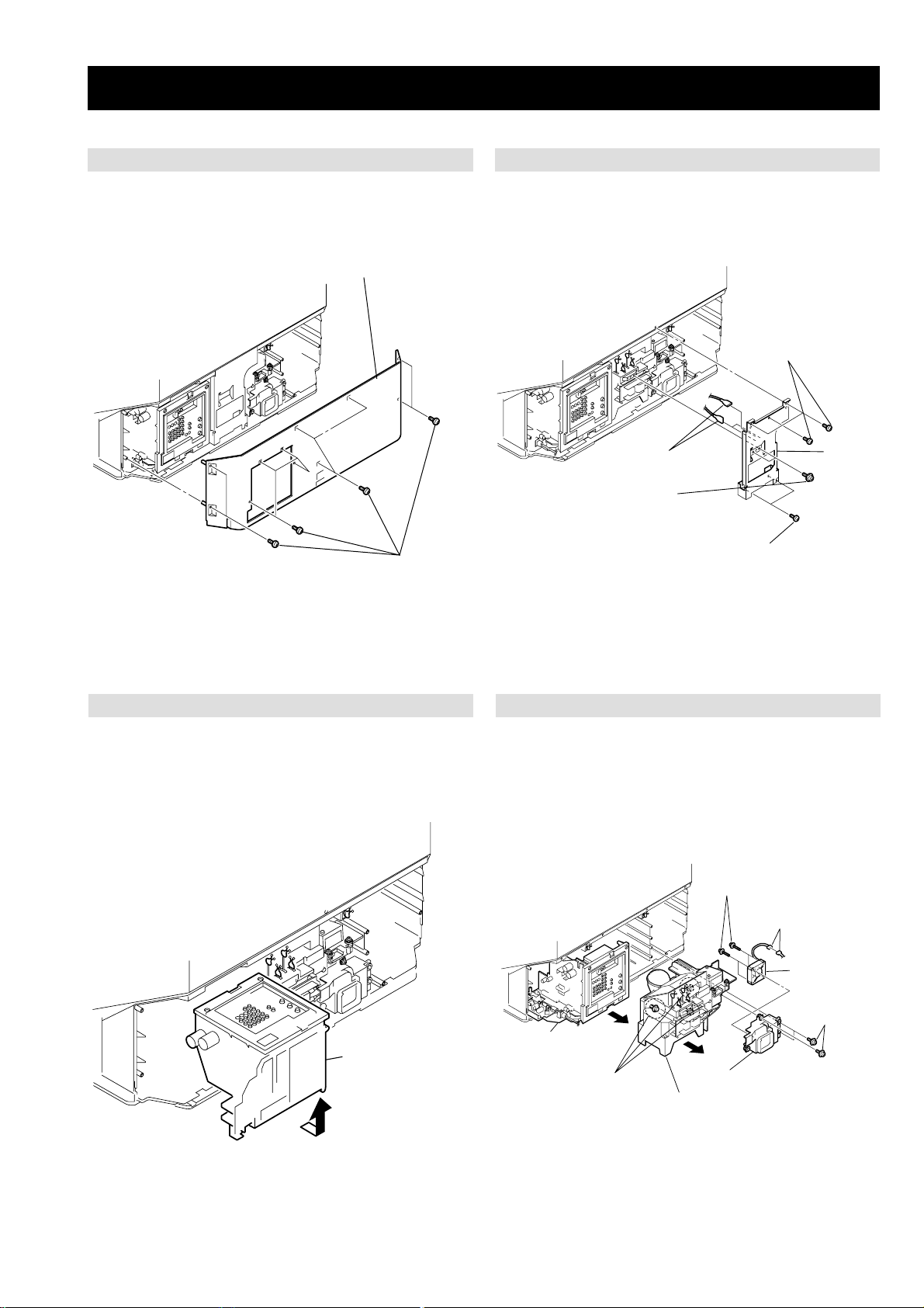
SECTION 3 DISASSEMBLY
2
Rear cover
KF-50/60SX300
RM-906
3-2. CENTER PILLAR REMOVAL3-1. REAR COVER REMOVAL
1
Three screws
(+BVTP 4x16)
Three
4
fasten tags
3
Two screws
(+PSW 3x8)
5
Center
pillar
Eleven screws
1
(+BVTP 4x16)
2
Two screws
(+BVTP 4x16)
3-4. CHASSIS, OPTICAL UNIT, DC FAN REMOVAL3-3. SERVICE POSITION
Four screws
8
(+PWH 4x35)
Connector
7
9
D. C. FAN
Chassis assembly
1
Chassis assembly
– 21 –
1
4
Three
special screws
5
3
Optical unit block
6
Fan bracket
with D. C. fan
Three screws
2
(+PWH 4x16)
Page 22
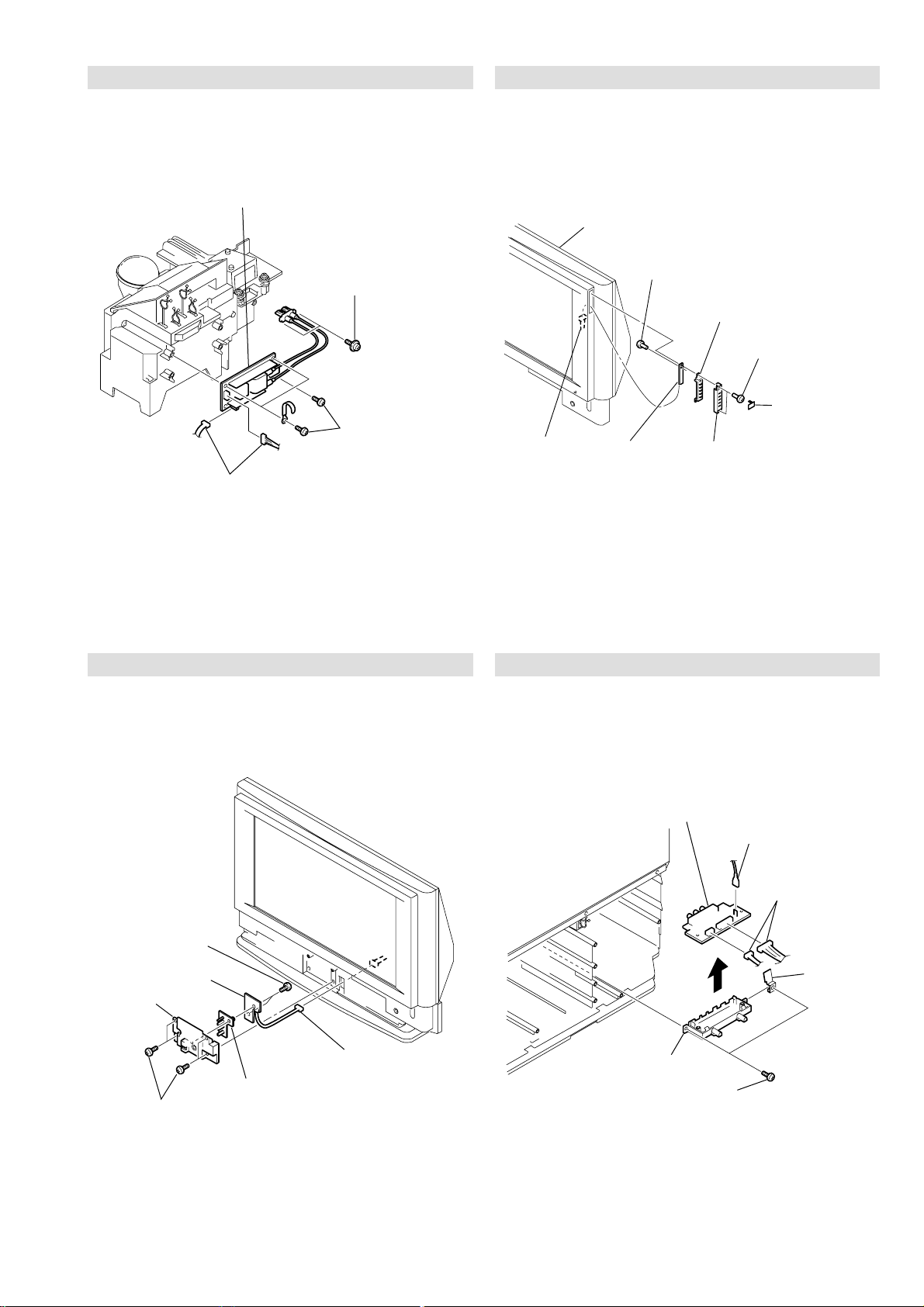
3-5. POWER BLOCK REMOVAL
Screen mirror block assembly
H1 bracket cap
Screw
(+BVTP 3x12)
Two screws
(+BVTP 4x16)
H1 bracket
H1 board
Connector
H1 button
1
2
3
4
5
6
Fasten tag
Spring
plate
Two
connectors
H3 bracket
Two screws
(+BVTP 3x12)
H3 board
1
2
6
5
3
4
4
Power supply block
2
Two screws
(+PWH 4x16)
3
Screw
(+BVTP 3x12)
1
Two connectors
KF-50/60SX300
RM-906
3-6. H1 BOARD REMOVAL
3-7. H2 BOARD REMOVAL 3-8. H3 BOARD REMOVAL
4
Two screws
(+BVTP 3x12)
H2 board
5
H2 bracket
2
Four screws
1
(+BVTP 4x16)
3
Connector
Light guide (LED)
6
– 22 –
Page 23
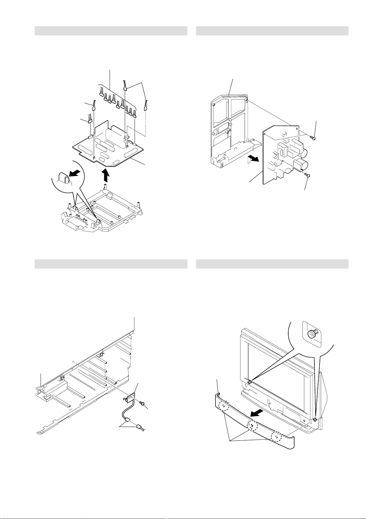
3-9. A BOARD REMOVAL
1 Screw
(+BVTP 4 X 16)
1 T w o screws
(+BVTP 4 X 16)
2
G bracket
3 G board
Four latches
Two ornamental screws
Front cover
assembly
1
2
2
Nine connectors
Fasten tag
3
4
Connector
Two claws
5
Two fasten tags
1
6
7
A board
KF-50/60SX300
RM-906
3-10. G BOARD REMOVAL
3-11. T BOARD REMOVAL 3-12. FRONT PANEL REMOVAL
3
Connector
1
T board
2
Screw
(+BVTP 3x12)
– 23 –
Page 24
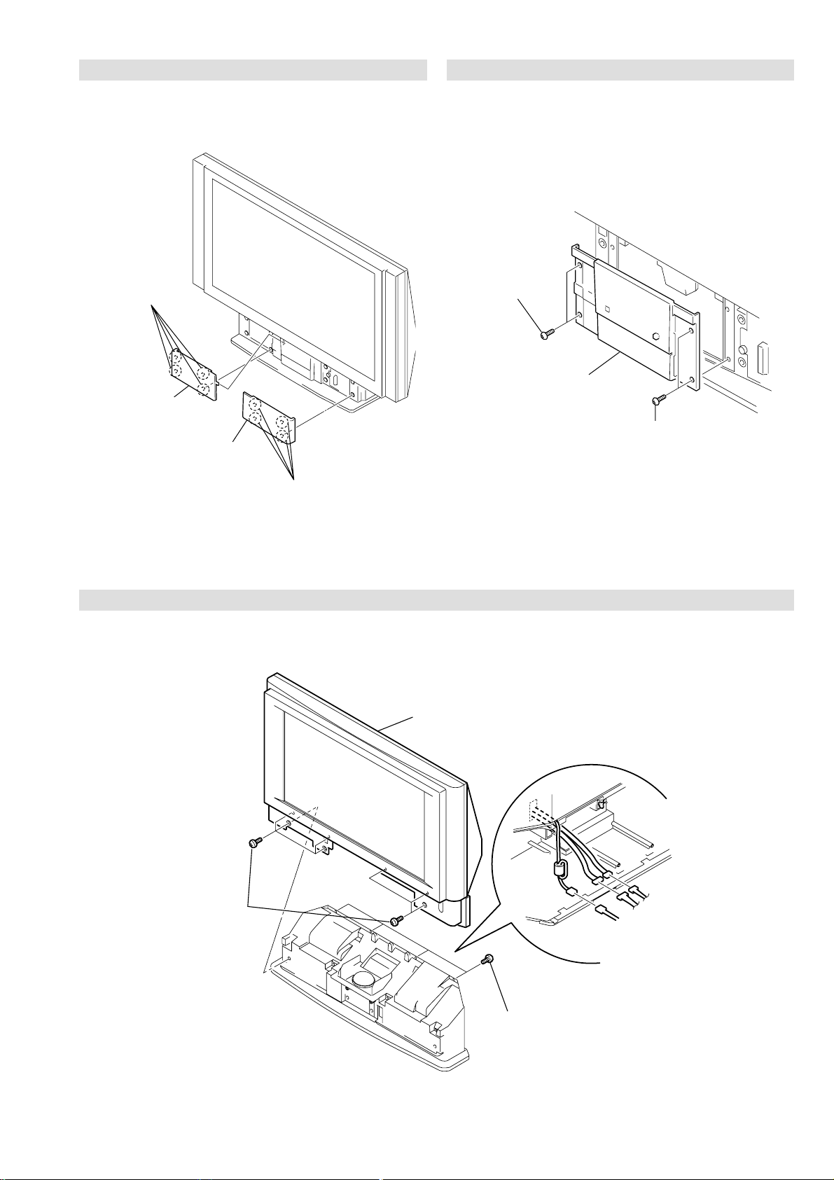
3-13. FRONT COVER REMOVAL
1 Four strikes
2 Front cover L
2 Front cover R
KF-50/60SX300
RM-906
3-14. CONTROL PANEL REMOVAL
1 T w o screws
(+BVTP 4 X 16)
2 Control panel
block assembly
1 T w o screws
(+BVTP 4 X 16)
1 Four strikes
3-15. SCREEN, MIRROR BLOCK ASSEMBLY REMOVAL
4
Screen mirror block assembly
3
Seven screws
(+BVTP 4x16)
– 24 –
2
Four screws
(+BVTP 4x16)
1
Three
connectors
Page 25
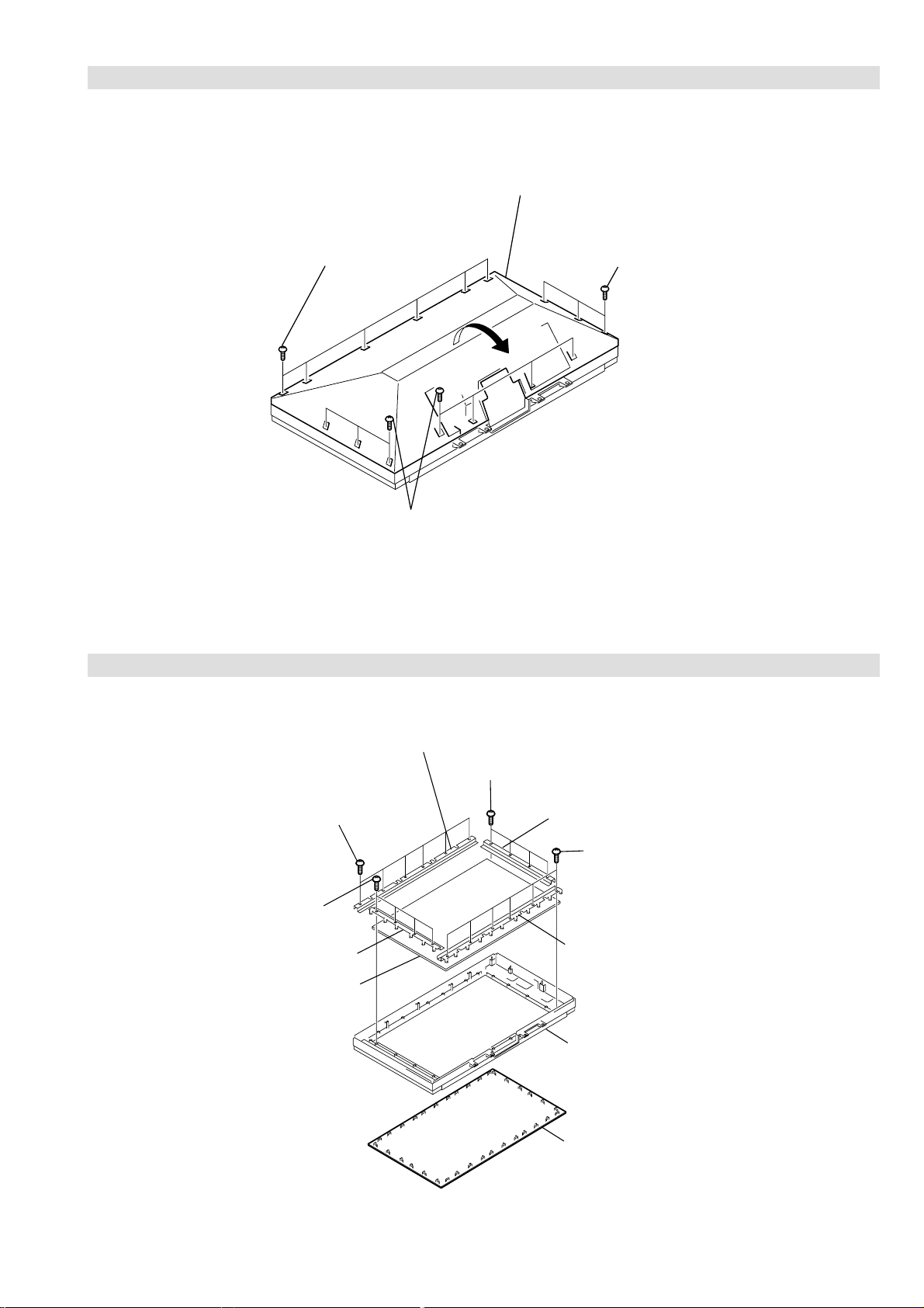
3-16. MIRROR COVER BLOCK ASSEMBLY REMOVAL
Mirror cover block assembly
KF-50/60SX300
RM-906
1 Six screws
(+BVTP 4 X 16)
2
1 Seven screws
(+BVTP 4 X 16)
3-17. CONTRAST SCREEN, DIFFUSION PLATE REMOVAL
1 Three screws
(+BVTP 4 X 16)
1 Six screws
(+BVTP 4 X 16)
1 Four screws
(+BVTP 4 X 16)
3 Screen holder (S)
4 Diffusion plates
2 Screen holder
1 Four screws
(+BVTP 4 X 16)
3 Screen holder (S)
1 Six screws
(+BVTP 4 X 16)
2 Screen holder
5Screen frame assembly
6 Contrast screen
– 25 –
Page 26
3-18. WOOFER BLOCK ASSEMBLY REMOVAL
1
KF-50/60SX300
RM-906
1 Two screws
(+BVTP 4 X 16)
2 Woof er block
assembly
3-19. SPEAKER REMOVAL 3-20. MIRROR REMOVAL
T w o screws
(+BVTP 4 X 16)
2 Fasten tags
1 Two screws (+BVTP 4 X 16)
3 Speaker (13 X 7cm)
1 T w o screws
(+BVTP 4 X 16)
5 T w o screws
(+BVTP 4 X 16)
6 Mirror
holder (R)
2 Mirror
holder (L)
7 Mirror
3 Three screws
(+BVTP 4 X 16)
4 Three mirror holders (U)
– 26 –
Page 27
SECTION 4 ELECTRICAL ADJUSTMENTS
KF-50/60SX300
RM-906
4-1. Adjustments with Commander
Service adjustments to this model can be performed using the
supplied remote Commander RM-906.
MUTE
ON SCREEN
DISPLAY
JOYSTICK
VOLUME +
VOLUME -
VIDEO STANDBY
TV STANDBY
SCREEN
FORMAT
Wide
Zoom
14 : 9
4 : 3
Smart
MENU
4-1-2. Programming the Remote Commander for
Operation in Service Mode
1. Press the VCR/TV/DVD b utton until the
TV LED lights.
2. Press and hold the yellow button for
approx. 5 seconds until the TV LED
flashes quickly .
3. Press 99999. All three LED’s should light.
The remote commander is now set to Service Mode.
4. To return the remote commander to normal operation mode
repeat steps 1. and 2. then press 00000. All three LED’s
should light.
The remote commander is now set to normal mode.
4-1-3. Setting the TV into Service Mode
1. Program the remote commander for operation in Service
Mode as described above.
2. Turn on the TV main power switch.
3. Press the video standby button on the remote
commander twice.
‘TT ’ will appear in the upper right corner of the screen.
Other status information will also be displayed.
4. Press ‘MENU’ on the remote commander to obtain the
following menu on the screen.
4-1-1. How to Select Each Mode
1. Selection of Mode Between PAL and NTSC
PAL mode : Enter PAL signal.
NTSC mode : Enter NTSC signal. (VIDEO input only)
2. Selection of Screen Format
1. Press ' (BLUE)' button on the commander to select a
different screen format '14 : 9' , '4 : 3' etc.
HFFNOISREVMVN)93.3v(4EL:uneMniaMecivreS
ecivreS
ngiseD
rorrE
:tceleS:metItceleS
5. Move to the corresponding adjustment item using the
up or down arrow b uttons on the Remote Commander.
6. Press the right arrow button to enter into the required menu item.
7. Press the ‘Menu’ button on the Remote Commander to quit the
Service Mode when all adjustments have been completed.
Note :
· After carrying out the service adjustments, to prevent the
customer accessing the ‘Service Menu’ switch the TV set
OFF and then ON.
4-1-4. Screen Display for Service Menu
ecivreS
yalpsiD
erutciP
oiduA
– 27 –
:tceleS:metItceleS:uneMsuoiverP
Page 28

KF-50/60SX300
RM-906
yalpsiD
ecnalabetihW
tnemtsujdayalpsiD
tnemtsujdaDSO
lortnocerutarepmeT
:tceleS:metItceleS:uneMsuoiverP
tnemtsujdayalpsiD
noitpircseD)xam,nim(tluafeDeulaV
JDALATNOZIROH)7402,0(00
JDALACITREV)3201,0(00
:tceleS:metItceleS:uneMsuoiverP
erutciP
sgnitteserutciP
ecnalabetihW
:tceleS:metItceleS:uneMsuoiverP
sgnitteserutciP
noitpircseD)xam,nim(tluafeDeulaV
NIAG_R)552,0(061051
NIAG_G)552,0(061631
NIAG_B)552,0(061131
SAIB_R)552,0(0829
SAIB_G)552,0(0808
SAIB_B)552,0(0838
FFO_NIAG_MRAW_R)721,821-(00
FFO_NIAG_MRAW_G)721,821-(00
FFO_NIAG_MRAW_B)721,821-(00
FFO_SAIB_MRAW_R)721,821-(00
FFO_SAIB_MRAW_G)721,821-(00
FFO_SAIB_MRAW_B)721,821-(00
FFO_NIAG_DLOC_R)721,821-(00
FFO_NIAG_DLOC_G)721,821-(00
FFO_NIAG_DLOC_B)721,821-(00
FFO_SAIB_DLOC_R)721,821-(00
FFO_SAIB_DLOC_G)721,821-(00
FFO_SAIB_DLOC_B)721,821-(00
FFO_NIAG_MACES_R)721,821-(00
FFO_NIAG_MACES_G)721,821-(00
FFO_NIAG_MACES_B)721,821-(00
FFO_SAIB_MACES_R)721,821-(00
FFO_SAIB_MACES_G)721,821-(00
FFO_SAIB_MACES_B)721,821-(00
noitpircseD)xam,nim(tluafeDeulaV
TNIOP_TALF)001,0(0753
OITAR_KP)51,0(00
CSTN_LAP_RUOLOC_BUS)36,0(2323
MACES_RUOLOC_BUS)36,0(2323
XAM_THGIRB)552,0(552552
NIM_THGIRB)552,0(0101
XAM_TSARTNOC)552,0(0505
NIM_TSARTNOC)552,0(00
:tceleS:metItceleS:uneMsuoiverP
oiduA
edomFFOEBB
stesffoybloD.V/larutaNEBB
stesffocimanyDEBB
stesffoameniCEBB
stnemtsujdalevelrefoowbuS
sdlohserhtnoitcetedoiduA
:tceleS:metItceleS:uneMsuoiverP
edomFFOEBB
noitpircseD)xam,nim(tluafeDeulaV
FFO_QERF_WS)04,5(0202
TESFFO_FFO_1DNAB)69,69-(00
TESFFO_FFO_2DNAB)69,69-(00
TESFFO_FFO_3DNAB)69,69-(00
TESFFO_FFO_4DNAB)69,69-(00
TESFFO_FFO_5DNAB)69,69-(00
FFO_SSENDUOL_EBB)86,0(00
:tceleS:metItceleS:uneMsuoiverP
ngiseD
eciveDhctiwSVA-9412AXC
eciveDrossecorPdnuoS-1143PSM
eciveDFI-x889ADT
eciveDLLP-xx06AUT
eciveDrossecorPoediV-7249PSV
redoceDamorhC-9102AXC
retliFbmoCD3-4083DXC
eciveDrelacSdnarossecorPlatigiD-A0549SPD
eciveDammaGlatigiD-GG1769DXC
eciveDrevirDDCL-R1007AXC
:tceleS:metItceleS:uneMsuoiverP
rotinomrorrE
)setuniM:sruoH(:EMITGNIKROW
:sretnuocrorrE
VOCPMAL:20E54
TORPPMAL:30E8
TORPNAF:40E55
TORPPMET:50E0
CII:60E0
MVN:70E0
RENUT:90E2
DNUOS:01E0
ETARNACS:21E4
DNEKCAB:41E2
HCTIWSVA:71E01
AMMAGLATIGID:22E3
srevirDDCL:32E6
TORPREKAEPS:42E0
33:28
:tceleS:metItceleS:uneMsuoiverP
:tceleS:uneMsuoiverP
– 28 –
Page 29

4-1-5. Operation Method for Adjustments
00
ffoedom'TT'
10
mumixamotlevelerutcipteS
20
muminimotlevelerutcipteS
30
%53otemuloVteS
40
%05otemuloVteS
50
%56otemuloVteS
60
%08otemuloVteS
70
noedomgniegA
80
noitidnoCgnippihS
11
tnemtsujdaerutciPbuS
21
tnemtsujdaruoloCbuS
31
tnemtsujdassenthgirBbuS
51
tsetliocnoitatoR
61
%05levelerutciP
91
elbasiD/elbanEedoMyrotcaF
12
RKEDAnoitanitseD
22
LBnoitanitseD
42
UnoitanitseD
13
)sehcni06/05(noitcelessehcnI
23
galfelbanekcitSyromeM
33
tnemtsujdaDCLreV-roH
43
galfrotcelesJPR
53
noitcelsledomediW
63
tsetno/ffoMV
93
gninutotuaotsseccatceriD
24
tsetrefoowbuS
34
dnuosAlauDtceleS
44
dnuosBlauDtceleS
54
dnuosonoMtceleS
64
dnuosoeretStceleS
94
nigrivsaMVNteS
35
elbasid/elbanenoitaludomrevOMF
85
tsetkcitSyromeM
26
elbasid/elbanednabesabmorfMA
37
)47.6/5.6(metsys2K/DnotiewZelbanE
47
)47.6/5.6(metsys3K/DnotiewZelbanE
87
tfelllufecnalaB
97
thgirllufecnalaB
78
tsetsyeklacoL
19
edommooz9:41teS
39
edommooz9:61teS
49
edommoozMOOZteS
59
edommooz3:4teS
69
)66XFrof(edommooztramSteS
99
unememiTgnikroWdnarorrEyalpsiD
TV STANDBY
MUTE
Write data to NVM
TV MODE
DIGITAL /
ON SCREEN
DISPLAY
VIDEO STANDBY
KF-50/60SX300
RM-906
4-3. TEST-TEST MODE
Is available by programming the Remote Commander for operation
in Service Mode [ As shown on Page 27 ] then pressing the VIDEO
button twice, OSD 'TT' appears. The functions describe below are
available by selecting the two numbers. To release 'Test Test Mode',
press 00, or switch the TV into Stand-by mode.
Copy PAL data to NTSC
JOYSTICK
VOLUME +
VOLUME -
1. Functions of Keys on Commander
• v V b B: Changes data value. (up or down)
: Marker moves up, down, or to the left or right.
(in fine adjustment mode)
• (OK) : Switches marker moving method.
(in fine adjustment mode)
joystick (v, V, b, B) keys c 1 and 4 buttons
4-2. Screen Center Adjustment
1. Input a monoscope PAL signal in wide mode.
2. Go into the Service mode; Display adjustment.
3. For Horizontal adjustment; modify to centre left-right.
4. For Vertical adjustment; modify to centre up-down.
5. Display PC input with XGA 60Hz resolution.
6. Check picture is not hidden on the top.
SCREEN
FORMAT
Wide
Zoom
14 : 9
4 : 3
Smart
MENU
– 29 –
Page 30

MEMO
KF-50/60SX300
RM-906
– 30 –
Page 31

5-1. BLOCK DIAGRAMS (1)
10
+17V
G ( )
POWER SUPPLY
5
1
T1601
3
9
8
11
12
13
14
16
15
17
9
18
8
1
2
IC1601
POWER SUPPLY
CONTROLLER
1
V SENSE
2
F/B
CT
4
RT
8
9
VC 1
OCP
3
TIMER
6
18
16
15
14
12
10
VD
VG
VG (L)
VC 2
VS
VB
PH1601
PHOTOCOUPLER
T1603
1
3
IC1602
REGULATOR
TO A BOARD
CN6202
7
6
CN1606
AU -15V
-DC
+DC
D1607
4
3
1
4
2
T1605
CN1601
D1608,
D1612,
D1635,
D1636
3
MOSFET
TRANSISTOR
USED BY
SWITCHING
CIRCUIT Q1606
MOSFET
TRANSISTOR
USED BY
SWITCHING
CIRCUIT Q1607
1
2
4
3
BARRIER
DIODE
D1623
AU +15V 2
1
+33V
+11V
+5V
D1626
+4.5V
D1624
D1625 PS1602
AU +15V
AU -15V
AU GND
AU GND
AU GND
+15V
-15V
PS1601
3
4
5
3
1
CN1602
POWER
SUPPLY
BLOCK
RELAY
RY1601
MAIN RECT
D1602
FH1601
1
3
4
1
3
1
2
1
CN1616
CN1615
CN1614
BIMETAL
MAIN SW
AC
AC
AC
AC
MAIN SW
BIMETAL
5
6
POWER
CONTROL
CIRCUIT
Q1603
Q1604
Q1605
D1601
CONVERTER
AND
PROTECT
Q1601
Q1602
4
6
D1614
IC1603
REGULATOR
SUB -7V
1 3
Q1608
POWER-CTL
AC DET
CN1605
TO A BOARD
CN6206
TO H2 BOARD
CN4402
PFC
TUNER
TU1100
SCL
SDA
FM/AM
TO H3 BOARD
CN4302
CN2301
OSS
HP-L-OUT
3
HP-R-OUT
1
IC2300
HEADPHONE AMPLIFIER
3
1
6
7 24
RESET
AUDIO
AUDIO MUTE
PROCESSOR
2
3
60
67
25
21
MUTE
IC2000
SOUND
STBY
SWITCH
Q2400,
Q2401
POWER OFF
MUTE
Q2501
+5V
IC2300
27
28
X2000
71
72
+3.3V
STBY
SWITCH
Q2003
IC2400
AUDIO AMP WOOFER
930
10
AV LINK
AUDIO AMP
6
7
1
7
11
AU+
AU-
IC2500
AUDIO AMP
PS2000
PS2001
1
3
WOOFER SP
2
4
CVBS SLAVE
CVBS-MAIN
RESET AUDIO
LINE MUTE
REAR-R
REAR-L
RED 2
BLUE 2
GREEN 2
RED 1
GREEN 1
BLUE 1
C SLAVE
C-MAIN
AV LINK
KEY 1
KEY 2
J2200
SPEAKERS
CN2004
3
TO WOOFER
CN2003
1
R
L
AU+
AU+
AU-
AU-
A21
A23
A24
A26
FS1
A27
A28
A29
A30
A31
A22
FS2
A32
B32
A20
A13
A18
A17
A16AUDIO MUTE
4
CN6202
1
2
6
7
CN5201
A5
TO
SPEAKERS
TO G BOARD
CN1606
TO B BOARD
CN3100
IC4401
IR/RECEIVER
OUT
VCC
S4402 - S4406
H1 ( )
T ( )
STBY 5V
USER KEY, SIRCS
S1000
LAMP COV
LAMP
COVER
SWITCH
SIRCS
KEY 2
KEY 1
GND31
CN4404
4
5
2
3
CN1000
TO A BOARD
CN0001
TO A BOARD
CN2301
HEADPHONE R OUT
HEADPHONE L OUT
HEADPHONE SW
TO J BOARD
CN3800
CN4302
CN4303
V2-L
V2-R
V2-V
V2-Y
V2-C
1
3
4
7
9
5
1
3
H3( )
AV INPUT
HP OUT
J4302
HEADPHONES
J4301
L
R
VIDEO
1
3
4
2
TUNER, AUDIO,
CN4401
REGULATORS
D4401
LAMP LED
4
5
STBY LED
7 POW ON
H2 ( )
Q4407
Q4401
LED INDICATORS
D4402
Q4404
SW+
SW+54
CN4402
CN1607 AND CN1615
4
63
D4405
S4401
R
G
Q4405
Q4406
1
+7V
R
G
Q4402
Q4403
TO G BOARD
- 31 -
A ( )
TO A BOARD
CN0001
Page 32

5-1. BLOCK DIAGRAMS (2)
TO A BOARD
CN5201
B ( )
CN3100
H2SB4
A5
KEY 2
A6
IR-DATA
A7
LUMISPONDER
A8
EPG MODE
A9
OCP-OVP
A10
OCP-FLAG
A11
MAIN-SW
A12
DG SW
A13
KEY 1
A14
SIRCS
B14
HV PROT
A15
LED
A16
AUDIO MUTE
LINE MUTE
A17
AUDIO RESET
A18
AGC DEFEAT
A19
AV LINK
A20
CSEL
B28
N/U
B29
N-RESET
B30
DQP V COMP
C6
H TRAP
B12
ROTATION
B13
C31 SDA 3.3V
C30 SCL 3.3V
B32 CVBS MAIN
C15
1 HOP MUTE
B31
AC MONITOR
C28
SDA DP1
C29
SDA DP1
MICRO, 3D COMB
BUFFER
Q5519
BUFFER
Q5503
BUFFER
Q5550
B
AC MONITOR
CV/Y/INT
Y
C
SDA
SCL
X3800
BUFFER
Q3811
BUFFER
Q3802
BUFFER
Q3800
CVBS MAIN
CV/Y/INT
37
38
1
34
39
38
FILTER
FL3801
SDA
SCL
CERA
CVBS/YIN
H SYNC
V SYNC
23
IC3802
SECAM REF
VTIM
HTIM
X433/358
BUFFER AMP
& SWITCH
Q3805, Q3806,
Q3816
FILTER
FL3800
23
+5V
14
15
28
BUFFER
Q3803
BUFFER
Q3801
SWITCH
Q3807
SWITCH
Q3808
BUFFER AMP
Q3812, Q3814
X3801
IC3801 IC3800
110
111
ADDR11
112
ADDR9
113
ADDR8
114
ADDR7
117
ADDR6
118
ADDR5
119
ADDR4
120
ADDR3
123
ADDR2
124
ADDR1
125
ADDR0
126
ADDR10
129
BA1
130
BA0
131
XCS
132
XRAS
133
XCAS
134
XWE
135
DQM
12
14
1930
59
62
4
2
9
VIN
RYO
ACO
RT
RB
REFCLK
VTIM
HTIM
DQ7
DQ6
DQ5
DQ4
DQ3
DQ2
DQ1
DQ0
DQ15
DQ14
DQ13
DQ12
DQ11
DQ10
DQ9
DQ8
SDCK
85
86
87
88
89
94
95
96
97
98
99
100
103
104
105
106
107
FB-M2
1K
H2S
SCL
SDA
V2S
+5V
RX
TX
GR3
B
Y
C
CN3400
1
5
9
CN3401
6
9
11
4
3
7
1
CN0004
3
4
TO C BOARD
CN3004
TO C BOARD
CN3004 &
CN3007
R3404
R3407
R3411
R3414
IC0001
H2S
103
H SYNC
OCP-OVP
12
IR DATA
SIRCS
KEY 2
KEY 1
N-RESET
DGC-SW
MAIN-SW
HV PROT
AV-LINK
A(10)
A(11)
A(12)
A(13)
A(14)
A(15)
A(16)
A(17)
A(18)
A(19)
P2.15
11
P2.14
8
P2.11
6
P2.9
5
P2.8
127
P5.3
124
P5.0
126
P5.2
101
P6.6
100
P6.5
93
P5.14
91
P3.13
90
P3.12
82
P3.8
81
P3.7
80
P3.6
78
P3.4
LED
77
P3.3
CSSDRAM
10
P2.13
A(0)
37
A(1)
36
A(2)
35
A(3)
34
A(4)
33
A(5)
27
A(6)
26
A(7)
24
A(8)
23
A(9)
25
28
29
30
38
39
A14/RAS
40
A15/CAS
22
P4.0/A16
19
P4.1/A17
18
P4.2/A18
17
P4.3/A19
OCP-FLAG
EPG-MODE
LUMISPONDER
AGC DEFEAT
12C-DISABLE
LINE MUTE
RESET-AUDIO
AUDIO MUTE
37
CKECKE
35
A11
34
A9
33
A8
32
A7
31
A6
30
A5
29
A4
26
A3
25
A2
24
A1
23
A0
22
A10
21
BA1
20
BA0
19
/CS
18
/RAS
17
/CAS
16
/WE
15
DQM
13
DQ7
11
DQ6
10
DQ5
8
DQ4
7
DQ3
5
DQ2
4
DQ1
2
DQ0
53
DQ15
51
DQ14
50
DQ13
48
DQ12
47
DQ11
45
DQ10
44
DQ9
42
DQ8
38
CLK
V SYNC
BLANK/
RS OUT
P2.10
P3.0
P3.1
P3.15
CVBS 1A
P3.11
P3.10
UDQM
MEMCLK
CLKEN
LDQM
CSROM
V2S
102
FB-M2
105
XTAL 1
108
X0001
109
XTAL 2
AC ON/OFF
7
BUFFER
Q0075
IC0007
4 5
AC MONITOR
IC0002
CSSD
RAM
D(0)
D(1)
D(2)
D(3)
D(4)
D(5)
D(6)
D(8)
D(9)
D(10)
D(11)
D(12)
D(13)
D(14)
D(15)
D(7)
D(7)
19
2
4
5
7
8
10
11
42
44
45
47
48
50
51
53
13
39
38
37
25
9
11
13
15
19
21
23
10
12
14
16
20
22
24
26
6
8
SCL33
SDA33
SCL33
6
SDA33
5
IC0003
CS
DQ0
DQ1
DQ2
DQ3
DQ4
DQ5
DQ6
DQ8
DQ9
DQ10
DQ11
DQ12
DQ13
DQ14
DQ15
DQ7
DQM
CLK
CKE
IC0005
OTP EPROM
Q7
Q0
Q1
Q2
Q3
Q4
Q5
Q6
Q8
Q9
Q10
Q11
Q12
Q13
Q14
Q15 A-1
/E1
/G
B
BA0/A12
BA1/A13
/RAS
/CAS
LOOM
23
A0
24
A1
25
A2
26
A3
29
A4
30
A5
31
A6
32
A7
33
A8
34
A9
22
A10
35
A11
20
21
18
17
15
16
/WE
A(0)
5
A0
A(1)
4
A1
A(2)
3
A2
A(3)
2
A3
A(4)
1
A4
A(5)
44
A5
A(6)
43
A6
A(7)
42
A7
A(8)
37
A8
A(9)
36
A9
A(10)
35
A10
A(11)
34
A11
A(12)
33
A12
A(13)
32
A13
A(14)
31
A14
A(15)
30
A15
A(16)
29
A16
A(17)
41
A17
A(18)
40
A18
A(19)
38
A19
74
75
NVM-WP
92
121
89
88
44
55
D0
59
D1
65
D2
71
D3
70
D4
64
D5
58
D6
54
D7
57
D8
63
D9
67
D10
72
D11
66
D12
62
D13
56
D14
51
D15
48
43
45
50
/WR
49
46
47
RD
CVBS-MAIN
RX
TX
CSSD
RAM
D(0)
D(1)
D(2)
D(3)
D(4)
D(5)
D(6)
D(7)
D(8)
D(9)
D(10)
D(11)
D(12)
D(13)
D(14)
D(15)
/WD
7
- 32 -
Page 33

5-1. BLOCK DIAGRAMS (3)
TO J BOARD
TO J BOARD
CN3806 AND
TO J BOARD
TO B BOARD
CN3809
CN3807
CN3805
CN3401
SCANRATE, BACKEND,
DIGITLA GAMMA, LCD DRIVERS
C ( )
IC3007
1
CN3009
3
G-PC
1
B-PC
5
R-PC
7
V-PC
9
CN3005
CN3006
CN3007
H-PC
2
G2
4
B2
6
Y-M
8
C-M
10
Y-S
12
C-S
2
FB2
4
FB1
6
R1
8
G1
10
B1
12
R1
2
Y
4
C
V-PC
H-PC
YUV 0
YUV 1
YUV 2
YUV 3
YUV 4
YUV 5
YUV 6
YUV 7
CLK
SCL 33
SDA 33
H-PC
MS-H-IN
V-PC
VS-OUT
HS-OUT
CLK-MS
X3001
VSP RESET
BLK
IC2501
CLOCK/CALENDAR
B0
85
D-A 0
B1
84
D-A 1
B2
83
CLK B
FRP
SHST
SDA
PRG
CLK R
FRP
SHST
SDA
PRG
D-A 2
B3
82
D-A 3
B4
81
D-A 4
B5
80
D-A 5
B6
79
D-A 6
B7
78
D-A 7
B8
77
D-A 8
B9
76
D-A 9
3
MCLKX
4
FRP
5
SHST
8
SDA
SCL
9
SCL
60
PRG
IC2701
R DRIVE
R0
85
D-A 0
R1
84
D-A 1
R2
83
D-A 2
R3
82
D-A 3
R4
81
D-A 4
R5
80
D-A 5
R6
79
D-A 6
R7
78
D-A 7
R8
77
D-A 8
R9
76
D-A 9
3
MCLKX
4
FRP
5
SHST
8
SDA
SCL
9
SCL
60
PRG
WP-256K
EXT
P-MUTE
WP-2K
3D GAMMA
IC3101
1
Q3101
Q3102
BUFFER
Q3105
IC2011
WP-2K
SCL
SDA
1
7
E0
WP IC2012
2
6
E1
3
5
E2
BUFFER
SWITCH
AND
Q2001
Q2002
IC3102
7
1
E0
6
2
E1
5
3
E2
1
2
IC3003
IC3004
HS
8
H-IN
VS
9
V-IN
12
Y IN 0
13
Y IN 1
14
Y IN 2
15
Y IN 3
16
Y IN 4
17
Y IN 5
18
Y IN 6
19
Y IN 7
26
ITUCLK-IN
C0
28
C IN 0
C1
29
C IN 1
C2
30
C IN 2
C3
31
C IN 3
C4
34
C IN 4
C5
35
C IN 5
C6
36
C IN 6
C7
37
C IN 7
4
SCL
7
SDA
10
H-IN 2
11
V-IN 2
22
V OUT
23
H OUT
27
CLKF-IN
73
X IN
74
X OUT
2
RESET
141
FBL1
PCLK1
OSD-H
OSD-V
R1.0
R1.1
R1.2
R1.3
R1.4
R1.5
R1.6
R1.7
G1.0
G1.1
G1.2
G1.3
G1.4
G1.5
G1.6
G1.7
B1.0
B1.1
B1.2
B1.3
B1.4
B1.5
B1.6
B1.7
R IN 1
G IN 1
B IN 1
R IN 2
G IN 2
B IN 2
100
101
102
103
106
107
108
109
110
111
114
115
131
132
133
136
137
138
80
72
77
82
83
84
85
88
89
90
93
94
95
98
99
H-OUT
V-OUT
R-OUT 0
R-OUT 1
R-OUT 2
R-OUT 3
R-OUT 4
R-OUT 5
R-OUT 6
R-OUT 7
G-OUT 0
G-OUT 1
G-OUT 2
G-OUT 3
G-OUT 4
G-OUT 5
G-OUT 6
G-OUT 7
B-OUT 0
B-OUT 1
B-OUT 2
B-OUT 3
B-OUT 4
B-OUT 5
B-OUT 6
B-OUT 7
R-VIDEO
G-VIDEO
B-VIDEO
R-OUT
G-OUT
B-OUT
INVERTER
2 4
EXPANDER
SDA
14
SCL
15
SCL
1
SDA
2
IC3006
PORT
DAC4
DAC4
DAC4
DAC4
IC2009
PCLK1
3
5
4
1
RESET
WC
SCL
SDA
PCLK1
PCLK1
B OUT 0
B OUT 1
B OUT 2
B OUT 3
B OUT 4
B OUT 5
B OUT 6
B OUT 7
G OUT 0
G OUT 1
G OUT 2
G OUT 3
G OUT 4
G OUT 5
G OUT 6
G OUT 7
R OUT 0
R OUT 1
R OUT 2
R OUT 3
R OUT 4
R OUT 5
R OUT 6
R OUT 7
H-OUT
V-OUT
SCL
SDA
RESET
P-MUTE
PRG
FRPN
FRP
SCL 33
SDA 33
29
3
4
5
6
7
8
9
10
13
14
15
16
17
18
19
20
23
24
25
26
27
28
29
30
31
32
33
34
35
66
22
21
23
36
37
PCLK1
B IN 2
B IN 3
B IN 4
B IN 5
B IN 6
B IN 7
B IN 8
B IN 9
G IN 2
G IN 3
G IN 4
G IN 5
G IN 6
G IN 7
G IN 8
G IN 9
R IN 2
R IN 3
R IN 4
R IN 5
R IN 6
R IN 7
R IN 8
R IN 9
HSYNC1
VSYNC1
R SCL
R SDA
RESET
MUTE
LCD PRG
LCD FRPX
LCD FRP
H SCL
H SDA
IC3103
B OUT 0
B OUT 1
B OUT 2
B OUT 3
B OUT 4
B OUT 5
B OUT 6
B OUT 7
B OUT 8
B OUT 9
G OUT 0
G OUT 1
G OUT 2
G OUT 3
G OUT 4
G OUT 5
G OUT 6
G OUT 7
G OUT 8
G OUT 9
R OUT 0
R OUT 1
R OUT 2
R OUT 3
R OUT 4
R OUT 5
R OUT 6
R OUT 7
R OUT 8
R OUT 9
LCD HST
LCD HCK1
LCD HCK2
LCD ENB
LCD VCK
LCD VST
LCD PCG
LCD CLR
R0
1
R1
2
R2
3
R3
4
R4
5
R5
6
R6
7
R7
8
R8
9
R9
10
G0
37
G1
38
G2
39
G3
40
G4
41
G5
42
G6
43
G7
44
G8
45
G9
46
B0
51
B1
52
B2
53
B3
54
B4
55
B5
56
B6
57
B7
58
B8
59
B9
60
HST
25
HCK1
26
HCK2
17
ENB1
24
VCK1
18
VST1
19
PCG1
11
CLR1
12
HCK1
HCK1
HCK2
HCK2
HCK1
HCK2
ENB1
VCK1
VST1
PCG1
CLR1
IC2007
HST
4
A3
HST
5
A4
6
A5
8
A7
7
A6
9
A8
HCK1-R
14
Y5
HCK2-R
13
Y6
HST R
16
Y3
HCK1-G
15
Y4
HCK2-G
12
Y7
HST G
11
Y8
IC2006
HST
4
A3
2
A1
3
A2
5
A4
6
A5
7
A6
8
A7
9
A8
HCK1-B
18
Y1
HCK2-B
17
Y2
HST B
16
Y3
ENB
15
Y4
VCK
14
Y5
VST
13
Y6
PCG
12
Y7
CLR
11
Y8
SID OUT
SH OUT 1
SH OUT 2
SH OUT 3
SH OUT 4
SH OUT 5
SH OUT 6
SH OUT 7
SH OUT 8
SH OUT 9
SH OUT 0
SH OUT 1
SH OUT 2
SID OUT
SH OUT 1
SH OUT 2
SH OUT 3
SH OUT 4
SH OUT 5
SH OUT 6
SH OUT 7
SH OUT 8
SH OUT 9
SH OUT 0
SH OUT 1
SH OUT 2
57
51
49
47
45
43
41
35
33
31
29
27
25
53
57
51
49
47
45
43
41
35
33
31
29
27
25
53
SID OUT
B-SIG 01
B-SIG 02
B-SIG 03
B-SIG 04
B-SIG 05
B-SIG 06
B-SIG 07
B-SIG 08
B-SIG 09
B-SIG 10
B-SIG 11
B-SIG 12
V COM OUT
SID OUT
R-SIG 01
R-SIG 02
R-SIG 03
R-SIG 04
R-SIG 05
R-SIG 06
R-SIG 07
R-SIG 08
R-SIG 09
R-SIG 10
R-SIG 11
R-SIG 12
V COM OUT
Q2502
Q2504
Q2702
Q2704
V COM OUT
V COM OUT
STBY 5V
IC4000
BUFFERS AND
AMPLIFIERS
67
Q4009 Q4010
Q4011 Q4012
Q4016 Q4017
FB2
68
R1
70
G1
72
B1
73
R2
78
G2
80
B2
82
Y
96
C
97
Y-M
100
C-M
102
Y-S
104
CS
106
V-PC
29
YUV 0
YUV 1
YUV 2
YUV 3
YUV 4
YUV 5
YUV 6
YUV 7
CLK
RESET
SCL 33
SDA 33
HS
32
H OUT
V OUT
DG OUT 0
DG OUT 1
DG OUT 2
DG OUT 3
DG OUT 4
DG OUT 5
DG OUT 6
DG OUT 7
CLK OUT
DB OUT 0
DB OUT 1
DB OUT 2
DB OUT 3
DB OUT 4
DB OUT 5
DB OUT 6
DB OUT 7
RESET
SCL
SDA
FLB1
FBL2
R IN 1
G IN 1
B IN 1
R IN 2
G IN 2
B IN 2
CVBS1
CVBS2
CVBS4
CVBS5
CVBS6
CVBS7
VS
39
25
24
23
22
21
9
8
7
51
C0
132
C1
128
C2
127
C3
126
C4
125
C5
124
C6
116
C7
115
40
28
10
R VIDEO
G VIDEO
G-CLP
Q4001
B-CLP
Q4002
R-CLP
Q4000
5V
B VIDEO
Q4015
Q4013
5V
BUFFER
Q4004
Q4014
BUFFER
Q4003
BUFFER
Q4005
B OSD CLP
G OSD CLP
R OSD CLP
IC4003
G
R
B
G
15
7
5
R
14
6
B
4
9
10
11
6
6
6
BUFFER
Q4007
BUFFER
Q4008
BUFFER
Q4009
G OUT
R OUT
B OUT
EXT
FB1
H PC
CLK G
FRP
SHST
SDA
SCL
PRG
IC2601
G DRIVE
G0
85
D-A 0
G1
84
D-A 1
G2
83
D-A 2
G3
82
D-A 3
G4
81
D-A 4
G5
80
D-A 5
G6
79
D-A 6
G7
78
D-A 7
G8
77
D-A 8
G9
76
D-A 9
3
MCLKX
4
FRP
5
SHST
8
SDA
9
SCL
60
PRG
SID OUT
SH OUT 1
SH OUT 2
SH OUT 3
SH OUT 4
SH OUT 5
SH OUT 6
SH OUT 7
SH OUT 8
SH OUT 9
SH OUT 0
SH OUT 1
SH OUT 2
57
51
49
47
45
43
41
35
33
31
29
27
25
53
SID OUT
G-SIG 01
G-SIG 02
G-SIG 03
G-SIG 04
G-SIG 05
G-SIG 06
G-SIG 07
G-SIG 08
G-SIG 09
G-SIG 10
G-SIG 11
G-SIG 12
V COM OUT
Q2602
Q2604
V COM OUT
P SIG-OB
B-SIG 01
B-SIG 02
B-SIG 03
B-SIG 04
B-SIG 05
B-SIG 06
B-SIG 07
B-SIG 08
B-SIG 09
B-SIG 10
B-SIG 11
B-SIG 12
PCG
HST-B
HCK1-B
HCK2-B
P SIG-OR
R-SIG 01
R-SIG 02
R-SIG 03
R-SIG 04
R-SIG 05
R-SIG 06
R-SIG 07
R-SIG 08
R-SIG 09
R-SIG 10
R-SIG 11
R-SIG 12
PCG
HST-R
HCK1-R
HCK2-R
PSG-OG
G-SIG 01
G-SIG 02
G-SIG 03
G-SIG 04
G-SIG 05
G-SIG 06
G-SIG 07
G-SIG 08
G-SIG 09
G-SIG 10
G-SIG 11
G-SIG 12
PCG
HST-G
HCK1-G
HCK2-G
HS-OUT
VS-OUT
R VIDEO
G VIDEO
B VIDEO
CLR
VST
VCK
ENB
CLR
VST
VCK
ENB
CLR
VST
VCK
ENB
SDA
SCL
BLK
CN2551
1
P SIG-OB
14
SIG-B6
13
SIG-B5
12
SIG-B4
11
SIG-B3
10
SIG-B2
9
SIG-B1
8
SIG-A6
7
SIG-A5
6
SIG-A4
5
SIG-A3
4
SIG-A2
3
SIG-A1
31
V COM
29
PCG
28
CLR
25
VST
24
VCK
23
ENB
17
HST
18
HCK1
19
HCK2
CN2601
1
P SIG-OR
14
SIG-B6
13
SIG-B5
12
SIG-B4
11
SIG-B3
10
SIG-B2
9
SIG-B1
8
SIG-A6
7
SIG-A5
6
SIG-A4
5
SIG-A3
4
SIG-A2
3
SIG-A1
31
V COM
29
PCG
28
CLR
25
VST
24
VCK
23
ENB
17
HST
HCK1
18
19
HCK2
CN2651
1
P SIG-OG
14
SIG-B6
13
SIG-B5
12
SIG-B4
11
SIG-B3
10
SIG-B2
9
SIG-B1
8
SIG-A6
7
SIG-A5
6
SIG-A4
5
SIG-A3
4
SIG-A2
3
SIG-A1
31
V COM
29
PCG
28
CLR
25
VST
24
VCK
23
ENB
17
HST
HCK1
18
19
HCK2
CN3004
HS IN
2
VS IN
1
SDA A
4
SCL A
3
BLANKING
6
R/R OSD
9
G/G OSD
711B/B OSD
- 33 -
Page 34

5-1. BLOCK DIAGRAMS (4)
5-2. CIRCUIT BOARD LOCATION
5-3. SCHEMATIC DIAGRAMS AND
PRINTED WIRING BOARDS
Note :
• All capacitors are in µF unless otherwise noted.
• pF : µµF 50WV or less are not indicated except for
electrolytic types.
• Indication of resistance, which does not have one for
rating electrical power, is as follows.
Pitch : 5mm
Electrical power rating : 1/4W
• Chip resistors are 1/10W
• All resistors are in ohms.
k = 1000 ohms, M = 1000,000 ohms
• : nonflammable resistor.
• : fusible resistor.
• : internal component.
• : panel designation or adjustment for repair.
• All variable and adjustable resistors have
characteristic curve B, unless otherwise noted.
• All voltages are in Volts.
• Readings are taken with a 10Mohm digital mutimeter.
• Readings are taken with a color bar input signal.
• Voltage variations may be noted due to normal production
tolerences.
•: B + bus.
• : B - bus.
• : RF signal path.
• : earth - ground.
• : earth - chassis.
Reference Information
RESISTOR RN
: METAL FILM
RC
: SOLID
FPRD
: NON FLAMMABLE CARBON
FUSE
: NON FLAMMABLE FUSIBLE
RS
: NON FLAMMABLE METAL OXIDE
RB
: NON FLAMMABLE CEMENT
RW
: NON FLAMMABLE WIREWOUND
: ADJUSTMENT RESISTOR
COIL LF-8L
: MICRO INDUCTOR
CAPACITOR TA
: TANTALUM
PS
: STYROL
PP
: POLYPROPYLENE
PT
: MYLAR
MPS
: METALIZED POLYESTER
MPP
: METALIZED POLYPROPYLENE
ALB
: BIPOLAR
ALT
: HIGH TEMPERATURE
ALR
: HIGH RIPPLE
Les composants identifiés par une trame et
par une marque sont d'une importance
critique pour la sécurité. Ne les remplacer
que par des pièces de numéro spécifié.
specified.
Note :
The components identified by shading
and marked are critical for safety.
Replace only with the part numbers
specified in the parts list.
Note :
CVM Board
A Board
S1 Board
VM
C
H
D1
A
J
A2
N
D
A1
D2
C
A
T
B
G
H2
H1
J
A
Power block
H3
C
CN3801
RIGHT OUT
1
RIGHT IN
2
LEFT OUT
3
LEFT IN
6
BLUE IN
7
MODE
8
AV1
GREEN IN
11
TO H3 BOARD
CN4303
CN3802
AV2
CN3803
AV3
CN3800
J2800
RED IN
15
BLANKING
16
VIDEO OUT
19
VIDEO IN
20
RIGHT OUT
1
RIGHT IN
2
LEFT OUT
3
LEFT IN
6
BLUE IN
7
MODE
8
GREEN IN
11
RED IN
15
BLANKING
16
VIDEO OUT
19
VIDEO IN
20
RIGHT OUT
1
RIGHT IN
2
LEFT OUT
3
LEFT IN
6
MODE
8
C IN
15
VIDEO OUT
19
VIDEO IN
20
1
5
C-FRONT
3
FRONT-L
7
FRONT-R
9
PCL
11
PCR
12
Y/CVBSFRONT
INTERFACE
CN3808
PC
5
12
15
14
13
1
2
3
SDA-PC
SCL-PC
V-PC
H-PC
R-PC
G-PC
B-PC
Q3859
Q3862
8
5
6
7
Q3861
BUFFER
Q3863
IC3801
CVBS/Y MAIN
SPEAKER-L
SPEAKER-R
L-ANALOG RF
R-ANALOG RF
Q3860
V-OUT-1S
V-OUT-2S
FRONT-L
SC3 IN-L
SC2 IN-L
SC1 IN-L
FRONT-R
2
9
11
C-MAIN
13
SCL
14
SDA
15
MUTE
17
MODE 1
18
MODE 2
19
MODE 3
20
23
24
25
26
27
28
29
32
33
IC3800
AUDIO/VIDEO SWITCH
LAST RF
AV2 OUT
CVBS Y MAIN
C MAIN
SCL
SDA
MUTE
MODE 1
MODE 2
AV3 OUT CVBS
MODE 3
AV2 OUT L/SPKR L
AV2 OUT L/SPKR R
ANALOG RF-L
FRONT L
AV3 IN-L
AV2 IN-L
AV1 IN-L
AV1 IN CVBS
ANALOG RF-R
DIGITAL RF
FRONT R
ANALOG RF
34
AV3 IN R
35
AV2 I R
36
AV1 IN R
38
AV1 OUT R
39
AV1 OUT L
40
AV3 OUT R
41
AV3 OUT L
43
45
Y SLAVE
47
C SLAVE
49
FRONT C
51
AV3 IN C
54
FRONT Y
56
AV3 IN Y
58
AV2 IN Y
60
62
64
J ( )
V-OUT-3S
MUTE
SWITCH
Q2804
V-OUT-2S
V-OUT-1S
SC2-OUT-R
SC2-OUT-L
SC3-IN-R
SC2-IN-R
SC1-IN-R
SC1 OUT-R
SC1 OUT-L
SC3 OUT-R
SC3 OUT-L
V-OUT-35
CVBS/Y SLAVE
C SLAVE
C-FRONT
C-IN-3
Y/CVBS-FRONT
V-IN-3
V-IN-2
V-IN-1
V-DIGITAL RF
V-ANALOG RF
A/V SWITCH
BUFFER
V-OUT-3B
AMP
Q3856
BUFFER
V-OUT-2B
AMP
Q3857
BUFFER
V-OUT-1B
AMP
Q3858
BUFFER
SPEAKER R
AMP
Q2802
BUFFER
SPEAKER L
AMP
Q2803
9V
AC ON-OFF
CVBS DIGITAL RF
CVBS/Y MAIN
C-MAIN
CVBS/Y SLAVE
C SLAVE
BLUE 1
GREEN 1
RED 1
BLK 1 FS1
GREEN 2
BLUE 2
BLK 2
RED 2
L-DIGITAL RF
R SPEAKER/HP
L SPEAKER/HP
R-DIGITAL RF
L-ANALOG RF
R-ANALOG RF
AV LINK
SDA
SCL
CVBS/ANALOG RF 35
FB2
BLK 2
FB1BLK 1
RED 1
GREEN 1
BLUE 1
RED 2
GREEN 2
BLUE 2
CVBS/Y MAIN
C-MAIN
CVBS/Y SLAVE
C SLAVE
V-PC
H-PC
R-PC
G-PC
B-PC
CN3804
1
3
4
6
7
9
10
11
12
14
15
16
17
19
20
22
23
25
26
29
32
33
CN3805
2
4
6
8
10
CN3806
2
4
6
8
CN3807
2
4
6
CN3809
7
9
5
3
1
TO C BOARD
CN3006
TO C BOARD
CN3005
TO C BOARD
CN3005
TO C BOARD
CN3009
- 34 -
Page 35

ABCDE F
G
HI JKLMN
O
1
2
3
4
5
6
HP OUT
7
8
1/3 TUNER, AUDIO, REGULATORS
9
10
11
COMPONENTS MARKED AS XX ARE NOT FITTED ON THIS MODEL
~ A Board Schematic Diagram [ Tuner, Audio, Regulators ] Page 1/3 ~
- 35 -
Page 36

TO H2 BOARD
CN4404
TO H1 BOARD
CN4404
ABCDE F
G
HI JKLMN
O
1
2
3
4
5
6
7
8
9
10
11
~ A Board Schematic Diagram [ Tuner, Audio, Regulators ] Page 2/3 ~
- 36 -
Page 37

ABCDE F
G
HI JKLMN
O
1
+
+
+
+
+
+
2
+
+
+
+
+
+
+
+
3
4
5
6
7
8
+
COMPONENTS MARKED AS XX ARE NOT FITTED ON THIS MODEL
9
+
+
+
+
+
+
+
+
+
10
11
~ A Board Schematic Diagram [ Tuner, Audio, Regulators ] Page 3/3 ~
- 37 -
Page 38

ABCDE F
elbaTegatloVCI elbaTegatloVCI elbaTegatloVCI elbaTegatloVCI
oNfeR
oNniP )V(egatloV
oNfeR
oNniP )V(egatloV
oNfeR
oNniP )V(egatloV
oNfeR
oNniP )V(egatloV
0032CI
10.4
0032CI85.0
0042CI
62.31-
0052CI
70
30.4
0042CI
10 019.380
55.020.4-210.4-90
60 3 0.01
0052CI
20 010
70 50 5 9.0110
G
HI JKLMN
O
~ A Printed Wiring Board Conductor Side ~
1
2
3
4
5
~ A Board Semiconductor Location Table ~
EDOID
0020D7-I1126CI7-B
6091D3-G2126CI8-B
8191D2-F3126CI4-B
4002D5-E
0026D8-C0020Q6-I
1026D9-C0031Q4-J
2026D9-D1031Q2-I
3026D9-I2191Q3-G
4026D4-C3191Q3-F
5026D7-C1002Q5-E
6026D5-B2002Q5-F
7026D2-F3002Q5-H
8026D3-G1042Q5-C
9026D2-H0052Q4-E
0126D3-F1052Q4-E
CI
0001CI3-G3052Q5-E
0002CI4-J4052Q5-F
0032CI4-G1026Q2-C
0042CI4-D2026Q2-C
0052CI3-F3026Q2-D
0026CI3-B4026Q7-C
1026CI9-H5026Q3-B
2026CI01-G6026Q6-B
3026CI6-B7026Q7-C
4026CI9-I8026Q7-C
5026CI2-B9026Q2-F
6026CI8-C1008Q3-J
7026CI9-B9038Q5-H
8026CI9-D1138Q5-G
9026CI9-E1848Q4-G
0126CI3-C
ROTSISNART
2052Q5-E
10
6
~ A Board Semiconductor Voltage Table ~
feR )s()e( )g()b( )d()c( feR )s()e( )g()b( )d()c(
0031Q7.21.24.81052Q06.00
7
1031Q1.21.20 2052Q000.5
1042Q007.43052Q000.5
0052Q1.01.06.04052Q0.50.50
0052Q1.01.06.04052Q0.50.50
8
~ A Board IC Voltage Table ~
9
11
- 38 -
Page 39

ABCDE F
1
B-#SSLE4A<...>-B..-KF-50/60SX300
G
HI JKLMN
O
2
COMB FILTER MEMORY
3
4
5
10
6
7
3D COMB FILTER
8
CHROMA DECODER
9
1/3 MICRO, 3D COMB
XX
XX
COMPONENTS MARKED AS XX ARE NOT FITTED ON THIS MODEL
11
~ B Board Schematic Diagram [ Micro, 3D Comb ] Page 1/3 ~
- 39 -
Page 40

ABCDE F
G
HI JKLMN
CN3004
TO C BOARD
CN3004 & CN3007
O
1
B-#SSLE4A<...>-B..-KF-50/60SX300
+
2
0
3
35V
xx
XX
xx
xx
XX
4
xx
XX
5
XX
XX
XX
XX
XX
XX
1K
2.7K
6
27K
XX
8.2K
100K
27K
10K
7
8
0
9
10
11
CN5201
~ B Board Schematic Diagram [ Micro, 3D Comb ] Page 2/3 ~
- 40 -
Page 41

1
M27V160-100K1-LE4001
OTP
100
XX
MICRO CONTROLLER
CMOS SDRAM
DEF 5V RESET
RESET
B-#SSLE4A<...>-B..-KF50/60SX300
M24C32-WMN6T(A)
1K
10K
22
50V
XX
2
ABCDE F
G
HI JKLMN
O
3
4
5
6
10
11
7
8
9
~ B Board Schematic Diagram [ Micro, 3D Comb ] Page 3/3 ~
- 41 -
Page 42

ABCDE F
G
HI JKLMN
O
~ B Printed Wiring Board Conductor Side A ~
~ B Board Semiconductor Location Table (A Side) ~
1
EDOID
0055D3-G
CI
1000CI3-B
3000CI3-B
2
3
5000CI1-B
0083CI2-D
1083CI3-D
2083CI3-E
ROTSISNART
5700Q5-C
9043Q2-G
0143Q3-H
5083Q4-D
6183Q4-D
0055Q4-G
7055Q3-H
9055Q3-G
4
5
6
~ B Printed Wiring Board Conductor Side B ~
7
8
9
~ B Board Semiconductor Location Table (B Side) ~
EDOID
2055D8-B
CI
2000CI01-G
6000CI01-H
ROTSISNART
1000Q9-F
2000Q9-F
3000Q9-G
0083Q9-E
1083Q9-F
2083Q9-E
3083Q9-F
6083Q9-E
1183Q9-D
2183Q8-D
4183Q8-D
3055Q9-B
10
11
- 42 -
Page 43

ABCDE F
G
HI JKLMN
O
1
1/4 SCANRATE, BACKEND, DIGITAL GAMMA, LCD DRIVERS
2
3
4
PLL
5
6
12-STAGE BINARY
COUNTER
7
XX
8
VOLTAGE DETECTOR
10
11
9
COMPONENTS MARKED AS XX ARE NOT FITTED ON THIS MODEL
~ C Board Schematic Diagram [ Scanrate, Backend, Digital Gamma, LCD Drivers ] Page 1/4 ~
- 43 -
Page 44

ABCDE F
G
HI JKLMN
O
1
2
3
4
5
6
7
RESET IC
OCTAL BUS BUFFER
8
12C BUS EEPROM
12C DIGITAL TEMP
9
SENSOR
10
11
~ C Board Schematic Diagram [ Scanrate, Backend, Digital Gamma, LCD Drivers ] Page 2/4 ~
- 44 -
Page 45

ABCDE F
+5V REGULATOR
COMPONENTS MARKED AS XX ARE NOT FITTED ON THIS MODEL
G
HI JKLMN
O
1
2
3
4
5
6
7
8
9
10
11
~ C Board Schematic Diagram [ Scanrate, Backend, Digital Gamma, LCD Drivers ] Page 3/4 ~
- 45 -
Page 46

ABCDE F
G
HI JKLMN
O
1
2
3
4
ANALOG MUX/DEMUX
5
6
COLOUR DECODER & SCANRATE CONVERTER
7
8
10
11
9
~ C Board Schematic Diagram [ Scanrate, Backend, Digital Gamma, LCD Drivers ] Page 4/4 ~
- 46 -
Page 47

ABCDE F
G
HI JKLMN
O
1
2
~ C Printed Wiring Board Conductor Side A ~ ~ C Board Location Table (A Side) ~
CI
9002CI5-G2052Q3-G
3
4
5
1102CI4-G4052Q3-G
2102CI4-H2062Q7-E
1052CI5-F4062Q7-E
1062CI6-E2072Q7-D
1072CI8-F4072Q8-D
1082CI6-C1003Q5-J
3003CI5-H2003Q5-J
4003CI6-I4003Q4-H
5003CI5-H1013Q8-G
6003CI5-I2013Q8-G
7003CI7-H0004Q6-I
8003CI4-H1004Q6-I
1013CI7-H2004Q6-I
2013CI7-G3004Q7-J
3013CI6-G4004Q7-I
0004CI5-J5004Q7-J
3004CI8-J9004Q8-J
ROTSISNART
1002Q4-G
2002Q4-G
0104Q8-J
6104Q8-J
6
10
11
7
8
9
- 47 -
Page 48

ABCDE F
G
HI JKLMN
O
1
~ C Printed Wiring Board Conductor Side B ~
~ C Board Location Table (B Side) ~
2
CI
6002CI6-H
7002CI6-H
3003CI 4-E
ROTSISNART
3
5013Q5-C
6004Q7-B
7004Q7-B
8004Q7-B
1104Q7-B
2104Q7-B
4
5
10
6
7
8
9
11
- 48 -
Page 49

ABCDE F
20us/div
20us/div
20us/div
1.1Vp-p (H)
1.1Vp-p (H)
TP1
TP2
TP3
2.3Vp-p (H)
G
HI JKLMN
O
10
J..-KF-50/60SX300
R2802
330
D2802
VARISTOR CHIP
UDZSTE-1713B
D3803
D3804
D3805
D3806
D2806
VARISTOR CHIP
D2807
UDZS-TE17-9.1B
D3807
UDZS-5.6B
D3808
UDZSTE-1713B
D800
UDZS-5.6B
D3810
UDZS-5.6B
D3811
UDZS-5.6B
D3812
UDZS-5.6B
UDZS-5.6B
VARISTOR CHIP
D2809
UDZS-TE17-9.1B
D2810
VARISTOR CHIP
D2811
UDZS-TE17-9.1B
UDZSTE-1713B
R3827
75
1/10W
C2840
XX
C2841
XX
VD2800
R2800
C2801
C2803
R3800
1/10W
D3800
R3803
1/10W
C2817
C2819
R3815
1/10W
R3816
1/10W
R3817
1/10W
UDZS-5.6B
D3813
D2808
C2829
C2831
D3814
R3826
75
1/10W
JR2818
L2800
JR2817
330
XX
XX
75
75
R2824
1/10W
XX
XX
75
75
75
D3809
XX
XX
XX
L2801
R2801
1k
R2803
1k
R3805
100
1/10W
R3801
75
1/10W
R3802
75
1/10W
R3804
75
1/10W
330
R2825
1k
R2826
330
R2827
1k
R3813
75
1/10W
R3819
100
1/10W
C0800
XX
R3818
75
1/10W
R2837
1k
1/10W
R2838
330
1/10W
R2839
1k
R3828
75
1/10W
R3829
75
1/10W
0
0
XX
VD2801
R2877
0
CHIP
UDZS-TE17-9.1B
L3808
XX
JR3808
0
CHIP
R2879
0
CHIP
R2880
L3809
XX
JR3809
0
CHIP
D2800
UDZS-TE17-9.1B
D2801
R2878
0
D2803
UDZS-TE17-9.1B
UDZS-5.6B
UDZS-5.6B
UDZS-5.6B
D2804
VARISTOR CHIP
0
D2805
UDZS-TE17-9.1B
D3802
UDZS-5.6B
UDZS-5.6B
UDZS-5.6B
D3801
1
CN3801
21P
RIGHT OUT
1
RIGHT IN
GND
GND
LEFT IN
BLUE IN
MODE
GND
GND
GND
RED IN
GND
GND
VIDEO IN
GND
2
3
4
5
6
7
8
9
NC
10
11
NC
12
13
14
15
16
17
18
19
20
21
AV1
2
LEFT OUT
GREEN IN
BLANKING
VIDEO OUT
3
4
5
CN3802
21P
RIGHT OUT
RIGHT IN
LEFT OUT
GND
GND
LEFT IN
BLUE IN
MODE
GND
AV LINK
GREEN IN
GND
GND
RED IN
BLANKING
GND
GND
VIDEO OUT
VIDEO IN
GND
1
2
3
4
5
6
7
8
9
10
11
NC
12
13
14
15
16
17
18
19
20
21
AV2
6
CN3803
21P
RIGHT OUT
RIGHT IN
LEFT OUT
GND
GND
LEFT IN
NC
MODE
GND
NC
7
GND
GND
C IN
GND
GND
VIDEO OUT
VIDEO IN
GND
NC
NC
NC
R2881
0
1
2
3
5
7
9
11
13
15
17
19
21
R2882
4
6
8
10
12
14
16
18
20
L3810
XX
JR3810
CHIP
0
0
8
D3818
UDZS-5.6B
D3815
9
TO H3 BOARD
CN4303
CN3800
12P
WHT
GND
GND
CVBS
GND
GND
GND
PCL
PCR
1
Y
2
3
C
4
5
6
7
L
8
9
R
10
11
12
UDZS-5.6B
UDZS-5.6B
R3861
0
CHIP
D3816
UDZS-5.6B
D3817
UDZS-5.6B
UDZS-TE17-9.1B
D3820
UDZS-TE17-9.1B
D2813
UDZS-TE17-9.1B
D3821
UDZS-TE17-9.1B
D3819
D2812
C2804
0.022
C2805
1000p
50V
C2806
0.022
25V
1000p
C2820
C2821
1000p
50V
C2822
C2823
1000p
C2832
0.022
1000p
C2834
0.022
C2835
1000p
R3830
100
1/10W
C2807
50V
R3807
100
1/10W
R3808
100
1/10W
R3809
100
1/10W
R3810
100
1/10W
R3811
1/10W
XX
XX
R2836
1/10W
C2833
50V
25V
75
330
R3831
100
R3832
100
C2842
C2843
R2808
470k
R2804
220
R2851
0
R2809
470k
1/10W
R2810
R2806
470k
220
R2811
R2852
0
470k
CHIP
1/10W
R3806
XX
R3812
100
1/10W
R2828
R2832
220
CHIP
1/10W
R2853
0
CHIP
R2834
R2830
220
470k
1/10W
CHIP
R2835
R2854
0
470k
R3814
100
1/10W
R3820
XX
R802
100
1/10W
R3821
100
1/10W
R3822
100
1/10W
R3823
100
1/10W
R3824
75
1/10W
R3825
100
1/10W
R2840
220
1/10W
R2855
R2845
0
CHIP
1/10W
R2842
R2846
220
470k
R2856
R2847
0
470k
CHIP
1/10W
R3833
XX
R3836
100
1/10W
R3834
75
1/10W
R3835
100
1/10W
XX
XX
J2800
C2810
C2808
C2811
35V
C2809
10V
C2826
35V
470k
R2833
470k
1/10W
C2827
35V
C2825
10V
C2838
25V
R2844
470k
1/10W
470k
C2839
25V
47
35V
1
10V
47
1
47
47
1
47
47
UDZS-TE17-9.1B
UDZS-TE17-9.1B
C2824
1
10V
C2836
1
10V
C2837
1
10V
C3864
1
10V
B
C3865
1
10V
B
SC1-OUT-R
D2830
SC1-IN-R
SC1-OUT-L
D2831
SC1-IN-L
C3800
XX
C3801
XX
C3802
XX
C3803
XX
SC2-OUT-R
D2832
UDZS-TE17-9.1B
SC2-IN-R
SC2-OUT-L
D2833
UDZS-TE17-9.1B
SC2-IN-L
C3804
XX
C3805
XX
C3806
XX
C3807
XX
SC3-OUT-R
D2834
UDZS-TE17-9.1B
SC3-IN-R
SC3-OUT-L
D2835
UDZS-TE17-9.1B
SC3-IN-L
FRONT-L
FRONT-R
BLUE-1
MODE1
GREEN-1
RED-1
BLK1
V-OUT-1B
V-IN-1
BLUE-2
MODE2
AV-LINK
GREEN-2
RED-2
BLK2
V-OUT-2B
V-IN-2
MODE3
C-IN-3
V-OUT-3B
V-IN-3
C-FRONT
Y/CVBS-FRONT
SC2-OUT-L
SC2-OUT-R
JR2801
XX
JR2805
XX
JR2809
XX
V-OUT-3S
CVBS/YSLAVE
C-SLAVE
C-FRONT
C-IN-3
Y/CVBS-FRONT
V-IN-3
V-IN-2
V-IN-1
V-DIGITALRF
V-ANALOGRF
V-OUT-1S
Q2802
MSD601-RST1
R2812
220
1/10W
Q2803
MSD601-RST1
R2813
220
1/10W
JR2802
JR2806
JR2810
XX
JR2813
XX
XX
XX
R2819
1/10W
1k
C3817
C3818
R2817
1/10W
JR2803
JR2807
JR2811
JR2814
0.1
0.1
C3819
0.1
16V
C3820
0.1
16V
J
R2820
1/10W
R2821
1k
1/10W
R2822
1/10W
R2823
1/10W
XX
XX
XX
XX
9V
C3826
16V
16V
A/V SWITCH
22k
22k
22k
22k
JR2808
JR2812
JR2815
XX
R3838
JR2804
XX
XX
CHIP
XX
L3811
1uH
C3825
0.1
C3824
0.1
0
0.1
16V
25V
0.1C3821
C3858
0.1
16V
C3822
0.1
C3823
XX
C2814
25V
C3808
0.1
16V
C3809
0.1
16V
25V
C2815
0.1
25V
0.1
C3810
35V
C3857
16V
C3828
XX
10C3827
50V
R3839
68k
R3841
68k
1/10W
COMPONENTS MARKED AS XX ARE NOT FITTED ON THIS MODEL
C2812
1
6.3V
C2813
1
6.3V
47
0.1
C3832
0.1
25V
MSD601-RST1
CN3808
15P
678910
12345
1112131415
9V-AUDIO
SPEAKER-R
PC INTERFACE
SPEAKER-L
C3814
XX
GND
GND
52
AV2 IN C
53
TRAP3
54
FRONT Y
55
VBIAS
56
AV3 IN Y
57
VGND
58
AV2 IN Y
59
VCC
60
AV1 IN CVBS
61
TC1
62
DIGITAL RF
63
TC2
64
ANALOG RF
R3843
39k
1/10W
Q3863
C SLAVE
AV3 IN C
FRONT C
TP 3
TP 1
REXT
LAST RF
RGD4
RGD3
LDO
1 2 3 4 5 6 7 8 9 10111213141516171819
R3895
R3896
3.3k
3.3k
1/10W
1/10W
R3893
470
1/10W
L3816
0.47uH
TRAP2
RGD2
C3856
Y SLAVE
RGD1
XX
D3828
UDZS-5.6B
SC3-OUT-L
C3816
0.1
25V
DVCC
DGND
AV3 OUT CVBS
IC3800
CXA2149AQ-TL
AV SWITCH
LD1
AV2 OUT CVBS
TRAP1
C3834
0.1
25V
CVBS/YMAIN
V-OUT-2S
D3829
UDZS-5.6B
SC3-OUT-R
AV3 OUT L
AV3 OUT R
Y_MAIN
VCC
SCL_PC
SC1-IN-R
SC1-OUT-L
SC1-OUT-R
R-DIGITALRF
XX
C3859
C3860
0.1
16V
AV1 IN R
AV1 OUT L
AV1 OUT R
DIGITAL RF R
AV2 OUT R/SPEAKER R
AV2 OUT L/SPEAKER L
TP 2
C_MAIN
SCL
SDA
ADR
R3892
XX
C-MAIN
D3826
UDZS-5.6B
V_PC
SC2-IN-R
SC3-IN-R
FRONT-R
33343536373839404142434445464748495051
AV3 IN R
AV2 IN R
FRONT R
ANALOG RF R
DIGITAL RF L
AV1 IN L
AV2 IN L
AV3 IN L
FRONT L
ANALOG RF L
MUTE
MODE1
MODE2
MODE1
D3822
UDZS-5.6B
V_PC
D3827
UDZS-5.6B
IC3801
ST24FC21M6TR
4321
R3874
0
CHIP
32
31
AGND
30
29
28
27
26
25
24
23
22
ABIAS
21
AVCC
MODE3
20
MODE2
R0800
100
CHIP
R0801
100
CHIP
Q2804
MSD601-RST1
H_PC
C3849
8765
R3872
220
1/10W
R3873
SDA
SCL
R3846
XX
R3847
0
CHIP
B_PC
D3825
UDZS-5.6B
0.1
16V
R3875
47
1/10W
1k
C3861
0.1
16V
C2857
47p
50V
9V-AUDIO
R2849
R_PC
R3868
15k
1/10W
C3836
R2848
1/10W
XX
SCL_PC
47
35V
1k
V_PC
H_PC
SDA_PC
D3824
UDZS-5.6B
MSB709-RT1
R3869
15k
1/10W
R3876
47
1/10W
SDA_PC
C3862
C2859
10
50V
C2860
47
35V
Q3859
XX
L2802
L3812
R2850
1/10W
C2858
0.1
25V
1uH
1uH
9V
10k
R3871
1/10W
47
D3823
UDZS-5.6B
+5VA
FB001
0uH
R3870
100k
1/10W
9V
9V
AC-ON/OFF
G_PC
C2855
R3889
CHIP
10V
0
1
V-OUT-2S
V-OUT-3S
C2856
R3862
47k
1/10W
C3846
47
25V
R3863
C3847
R3866
1/10W
R3864
1/10W
C3848
V-OUT-1S
1
10V
47k
47
25V
22k
47k
47
25V
R3890
CHIP
R3865
22k
0
Q3856
MSD601-RST1
R3852
2.2k
MSD601-RST1
R3856
MSD601-RST1
R3867
22k
R-ANALOGRF
L-DIGITALRF
SC1-IN-L
SC2-IN-L
SC3-IN-L
FRONT-L
L-ANALOGRF
SPEAKER-R
SPEAKER-L
B_PC
G_PC
R_PC
2.2k
R3859
2.2k
R3880
1/10W
R3884
1/10W
C3842
Q3857
C3844
25V
Q3858
82
82
R3888
82
1/10W
0.1
25V
C3843
0.1
0.1
F
L-DIGITALRF
SPEAKER-R
SPEAKER-L
R-DIGITALRF
L-ANALOGRF
R-ANALOGRF
C3851
XX
C3852
XX
C3853
XX
V-OUT-2B
V-OUT-1B
+5VA
R3879
68
1/10W
C3867
100p
R3883
68
1/10W
C3868
100p
50V
R3887
68
1/10W
C3845
47
25V
V-OUT-3B
MODE3
C3866
100p
50V
Q3860
MSB709-RT1
MSB709-RT1
MSB709-RT1
L3814
1uH
V-DIGITALRF
CVBS/YMAIN
C-MAIN
CVBS/YSLAVE
C-SLAVE
BLUE-1
GREEN-1
RED-1
BLK1
GREEN-2
BLUE-2
BLK2
RED-2
AV-LINK
V-ANALOGRF
BLK2
BLK1
RED-1
GREEN-1
BLUE-1
RED-2
GREEN-2
BLUE-2
CVBS/YMAIN
C-MAIN
CVBS/YSLAVE
C-SLAVE
R3881
180
1/10W
Q3861
Q3862
L3815
R3894
XX
CHIP
9V
CN3804
35P
WHT
1
CVBS DIGITAL RF
2
GND1
3
CVBS/Y MAIN
4
C MAIN
GND 2
5
6
CVBS/Y SLAVE
C SLAVE
7
8
GND 3
9
BLUE 1
10
GREEN 1
11
RED 1
12
FS 1
13
GND 4
14
GREEN 2
15
BLUE2
16
BLK2
17
RED 2
18
GND5
19
L DIGITAL RF
20
R SPEAKER/HP
21
GND6
22
L SPEAKER/HP
23
R DIGITAL RF
24
GND7
25
L ANALOG RF
26
9V
C3841
0.1
AC-ON/OFF
SDA
0
SCL
C3850
XX
C3863
FB3800
0uH
22p
50V
R3877
180
+5VA
R3878
XX
+5VA
R3882
XX
R3885
180
+5VA
R3886
XX
R ANALOG RF
27
+9VA
28
GND8
29
AV LINK
30
AC-ON/OFF
31
+5VA
32
SDA
33
SCL
34
GND9
35
CVBS ANALOG RF
CN3805
10P
WHT
1
GND
2
FB2
3
GND
4
FB1
5
GND
6
RED-1
7
GND
8
GREEN-1
9
GND
10
BLUE-1
CN3806
8P
WHT
1
GND
2
RED-2
3
GND
4
GREEN2
5
GND
6
BLUE-2
7
GND
8
CVBS/Y MAIN
CN3807
6P
WHT
1
GND
2
C-MAIN
3
GND
4
CVBS/Y SLAVE
5
GND
6
C-SLAVE
CN3809
10P
RED
1
B_PC
2
GND
3
G_PC
4
GND
5
R_PC
6
GND
7
V_PC
8
GND
9
H_PC
10
GND
TO C BOARD
CN3006
TO C BOARD
CN3005
TO C BOARD
CN3009
~ J Board Waveforms ~
11
~ J Board Schematic Diagram [ AV Switch ] ~
- 49 -
Page 50

ABCDE F
elbaTegatloVCI elbaTegatloVCI
oNfeR
oNniP )V(egatloV
oNfeR
oNniP )V(egatloV
0083CI
19.1
0083CI
234.4
35.4334.4
45.4434.4
51.0534.4
63.4634.4
73.4734.4
81.0834.4
96.4934.4
119.3044.4
315.4144.4
418.4347.4
518.4544.4
619.8745.4
811.0945.4
910 155.4
020 255.4
225.4451.4
325.4555.4
425.4651.3
525.4851.4
624.4061.4
724.4161.5
824.4260.5
924.4368.4
034.4465.4
G
HI JKLMN
O
1
~ J Printed Wiring Board Conductor Side A ~
2
3
4
~ J Board Location Table (A Side) ~
EDOID
2182D4-C
3182D4-B
2382D3-D
3382D3-D
7183D4-C
0283D4-C
1283D4-B
3283D4-G
5283D3-G
6283D4-G
7283D3-G
8283D3-G
CI
0083CI3-B
1083CI3-G
ROTSISNART
2082Q4-C
3082Q4-B
0683Q4-G
1683Q4-F
2683Q4-F
~ J Board IC Voltage Table ~
5
6
7
8
9
10
11
~ J Printed Wiring Board Conductor Side B ~
- 50 -
~ J Board Location Table (B Side) ~
EDOID
008D8-D7083D8-D
0082D9-E8083D9-D
1082D01-D9083D8-D
2082D9-E0183D8-D
3082D01-D1183D8-D
4082D8-E2183D9-D
5082D9-E3183D9-C
6082D8-E4183D8-D
7082D9-E5183D7-C
8082D7-D8183D7-D
9082D7-D9183D8-C
0182D7-D2283D9-B
1182D8-D4283D9-B
0382D9-F9283D8-B
1382D9-F
4382D7-E4082Q7-G
5382D7-F6583Q7-C
0083D01-D7583Q8-C
1083D9-C8583Q9-C
2083D9-D9583Q8-C
3083D9-D3683Q8-F
4083D9-C
6083D01-C
ROTSISNART
Page 51

ABCDE F
1
2
3
4
G
HI JKLMN
O
5
6
7
8
9
10
11
~ G Board Schematic Diagram [ Power Supply ] ~
- 51 -
Page 52

ABCDE F
elbaTegatloVCI elbaTegatloVCI elbaTegatloVCI elbaTegatloVCI
oNfeR
oNniP )V(egatloV
oNfeR
oNniP )V(egatloV
oNfeR
oNniP )V(egatloV
oNfeR
oNniP )V(egatloV
1061CI
18.2
1061CI
76.4
1061CI
414.161
6061CI
22.1
28.181.12511.15132.5
32.290.4-617.551
7061CI
15.6
45.2014.01818.30322.1
60 218.4
6061CI15.634
G
HI JKLMN
O
~ G Printed Wiring Board Conductor Side ~
1
2
3
4
~ G Board IC Voltage Table ~
~ G Board Semiconductor
Voltage Table ~
feR )s()e( )g()b( )d()c(
6061Q6.1514.6512.403
7061Q-7.46.151
3061QDNG8.01.0
4061Q01.41.4
1061Q08.12.451
1061Q-5.00
5061QDNG01.4
~ H1 Printed Wiring Board Conductor Side ~
5
6
~ H3 Printed Wiring Board Conductor Side ~
~ H2 Printed Wiring Board Conductor Side ~
7
8
9
10
11
Note :
Portions of the circuit contained within
the marked areas as shown have high
voltages present. Use care to prevent
electric shock during inspection or repair.
An Isolation Transformer must be used
during any Service work to avoid possible
shock hazard due to live chassis. The
chassis of this receiver is directly
connected to the power line.
~ T Printed Wiring Board Conductor Side ~
- 52 -
Page 53

ABCDE F
SLR-325VCT31
D4401
1234567
RED
7P
CN4401
NC
GND
NC
LAMP LED
STBY LED
STBY +7V
POW ON
1/10W
100
R4402
G
R
SPR-325MVW
D4402
1/10W
470
R4404
16V
10
C4404
1/10W
100
R4403
1/10W
1k
R4408
DTC114EK
Q4401
1/10W
470
R4405
DTA114EKA
Q4402
2SC1623-L5L6
Q4403
50V
2.2
C4403
1/10W
100k
R4406
1/10W
47k
R4407
DTC114EK
Q4404
DTA114EKA
Q4405
1/10W
1k
R4411
MSD601-RST1
Q4406
G
R
SPR-325MVW
D4405
1/10W
47
R4409
12345
RED
5P
CN4402
GND
GND
GND
SW+
SW+
Q4408
XX
XX
R4414
XX
R4413
MSD601-RST1
Q4407
1/10W
47
R4412
1/10W
10k
R4410
CHIP
0
R4415
S4401
1
2
3
4
5
6
H2
H2.-KF-50/60SX300
TO A BOARD
CN0001
TO G BOARD
CN1607
COMPONENTS MARKED AS XX ARE NOT FITTED ON THIS MODEL
LED INDICATORS
S1000
1
2
3
WHT
3P
CN1000
GND
NC
LAMP COV
T
T..-KF-50/60SX300
LAMP COVER SWITCH
G
HI JKLMN
O
1
~ H1 Board Schematic Diagram [ User Key, Sircs ] ~ ~ H2 Board Schematic Diagram [ LED Indicators ] ~
2
3
USER KEY, SIRCS
16V
4
5
6
~ H3 Board Schematic Diagram [ AV Input, HP Out ] ~
7
8
~ T Board Schematic Diagram [ Lamp Cover Switch ] ~
9
10
11
- 53 -
Page 54

5-4. SEMICONDUCTORS
1E3-TB
D1N20R
D1NS4
ERA11-08
UF4005PKG23
1SS355TE-17
MA113-(TX)
UDZ-TE-1713B
UDZSTE-173.6B
UDZSTE-179.1B
2SA1023AK-T146-R
2SA1162-G
2SC1623-L5L6
2SD2114K
DTA114EKA-T146
DTC114EK
2SK2663
G
D
BA033T
CATHODE
ANODE
ANODE
CATHODE
CXD3804R-T6
PQ1CG2032FZ
PST9143NL
C
B
E
D10SC4M
D10SC6M
D10SC6MR
RD5.6M-B2
1
2
3
4
5
3
RD5.6M-B3
1
2
3
1
2
3
L7805CV/LSY
STP5NK40Z(033Y)
ST2310DHI
S
S-80743AL-47-S
S80727-SN-DQ-T1
2
1
3
2
1
B
C
E
B
E
C
CXA1875AM-T4 (16 pin)
K4S641632F-UC75T (54 pin)
M24C32-WMN6T(A) (8 pin)
TC74VHCT541AFT(EL)
TDA2822D013TR (8 pin)
TLC2932IPWR
1
TOP VIEW
CXA2019AQ-T4 (40 pin)
CXA2149AQ-TL (64 pin)
CXA7001R (100 pin)
DSP9450AA1T (144 pin)
VSP9417BC3G (144 pin)
LM75C1MX-5
1
2
3
4
M24256-BWMN6T
M24C02-MN6T(A)
PQ30RV11
SI-8033S
7
6
5
SI-8050S-LF1101
1
7
SBX3081-11
3
2
1
TDA7269A
TDA7482
115
UPC1093J-1-T
1
TOP VIEW
1
4
REF
CATHODE
ANODE
- 54 -
Page 55

MC74LVX8053
P-MQFP-128
MQFP144
LM75
PQ20VZ-U
M27V160
L7800
SI8050S
SI8033S
- 55 -
Page 56

5-5 IC BLOCK DIAGRAMS
A BOARD IC6201 BA033TA BOARD IC2500 TDA7269
7
9
11
A BOARD IC6208 PQ1CG2032FZ
+
-
-
+
4
1
REFERENCE
VOLTAGE
-
+
8
3
2
10
2
Vin
1 2
Vout
ON/OFF
PWM COMP
+
ON/OFF
-
ERROR AMP
-
Oadj
+
Vref
5
4
- 56 -
Page 57

A BOARD IC2000 MSP3411G
65 68 13 45 7 6
25
23
28
31
30
34
33
37
36
SBUS Interface
DEMODULATOR
IDENT
DFP
A/D
A/D
SCART Switching Facilities
I2C Interface
D/A
D/A
D/A
D/A
D/A
D/A
56
57
59
60
47
48
50
51
G BOARD IC1601 MCZ3001D
Remote
1
Vsense
5
SS
DVLD
15v/8v
7
4 3 2
Osc
Internal
ref 5v
Centre
F/B
18
Latch
OFF
Sel=34v
Timer
8
Driver
Reg. 10v
TSD
Level
Shift
Control
Logic
OCP
6
14
16
15
10
12
11
9
- 57 -
Page 58

SECTION 6
EXPLODED VIEWS
NOTE :
Items with no part number and no description are not
stocked because they are seldom required for routine
service.
The construction parts of an assembled part are indicated
with a collation number in the remarks column.
Items marked “*” are not stocked
since they are seldom required for
routine service. Some delay should
be anticipated when ordering these
items.
6-1. SCREEN AND COVER BLOCK
REF.NO. PART.NO DESCRIPTION REMARK REF.NO. PART.NO DESCRIPTION REMARK
- 58 -
KF-50/60SX300
RM-906
The components identied by shading
and mark are critical for safety.
Replace only with part number specied.
£
1 X-4041-950-1 COVER ASSY, FRONT (KF-50SX300)
X-4041-958-1 COVER ASSY, FRONT (KF-60SX300)
2 4-094-706-01 BUTTON, POWER
3 4-036-405-01 SPRING, COMPRESSION
4 7-685-648-79 SCREW +BVTP 3X12 TYPE2 IT-3
5 4-094-707-01 GUIDE (LED), LIGHT
6 4-095-607-11 BRACKET, H2
7 A-1405-808-A MOUNTED PC BOARD, H2
8 4-094-712-01 BUTTON, H1
9 X-4042-014-2 PLATE (50) ASSY, FOOT (KF-50SX300)
X-4042-015-2 PLATE (60) ASSY, FOOT (KF-60SX300)
10 A-1405-807-A MOUNTED PC BOARD, H1
11 4-099-707-01 BRACKET H1 (PAINTED)
12 X-4041-952-1 CAP REAR (L), ASSY
13 3-650-537-00 WASHER
14 4-094-695-31 COVER, REAR (KF-50SX300)
4-094-695-41 COVER, REAR (KF-60SX300)
15 1-825-580-11 LOUDSPEAKER (10CM)
16 X-4041-944-1 COVER (50) ASSY, MIRROR (KF-50SX300)
X-4041-954-1 COVER (60) ASSY, MIRROR (KF-60SX300)
17 4-077-752-02 HOLDER (L), MIRROR
18 4-078-871-01 MIRROR (50) (KF-50SX300)
4-097-650-01 MIRROR (60) (KF-60SX300)
19 4-077-731-02 HOLDER (R), MIRROR
20 4-077-669-01 HOLDER (U), MIRROR
21 X-4041-951-1 CAP REAR (R), ASSY
22 4-099-706-01 CAP H1 (PAINTED)
23 A-1604-990-A FRAME (50) ASSY, SCREEN (KF-50SX300)
A-1605-715-A FRAME (60) ASSY, SCREEN (KF-60SX300)
24 1-544-857-11 SPEAKER (13X7CM)
25 4-058-870-01 SCREW
3
4
6
5
7
9
10
1
2
18
23
12
25
15
16
14
17
20
21
19
13
22
24
13
n :
7-685-648-79
SCREW (WASHER HEAD) (+P4X35)
:
7-685-658-79
SCREW +BVTP 3X12 TYPE 2 IT-3
l : 7-685-663-79
SCREW +BVTP 4X16 TYPE 2 IT-3
O
: 7-685-663-71
SCREW +BVTP 3X14 TYPE 2 IT-3
8
25
l
l
l
l
l
l
l
l
l
O
O
O
O
n
n
O
11
Page 59

6-2. CABINET BLOCK
REF.NO. PART.NO DESCRIPTION REMARK REF.NO. PART.NO DESCRIPTION REMARK
- 59 -
: 7-685-658-79 SCREW +BVTP 3X12 TYPE 2 IT-3
KF-50/60SX300
RM-906
The components identied by shading
and mark are critical for safety.
Replace only with part number specied.
£
51 4-094-723-21 COVER, BOTTOM
52 4-098-512-01 DOOR, H3
53 4-094-757-01 SPRING, PLATE
54 *A-1405-806-A MOUNTED PC BOARD, H3
55 X-4041-946-1 CABINET (50) ASSY (KF-50SX300)
X-4041-956-1 CABINET (60) ASSY (KF-60SX300)
56 4-097-548-01 CUSHION, FOOT
57 *A-1405-811-A MOUNTED PC BOARD, T
58 A-1606-075-A LAMP BLOCK ASSY
59 *3-650-537-00 WASHER
60 4-094-747-11 DOOR, LAMP
51
52
54
53
60
58
59
56
56
57
55
Page 60

6-3. MAIN BRACKET BLOCK
REF.NO. PART.NO DESCRIPTION REMARK REF.NO. PART.NO DESCRIPTION REMARK
- 60 -
KF-50/60SX300
RM-906
The components identied by shading
and mark are critical for safety.
Replace only with part number specied.
£
100 4-096-934-11 BRACKET, MAIN
101 *A-1405-803-A MOUNTED PC BOARD, A
102 8-598-535-20 FRONT END BTF-EF411
103 1-419-965-11 COIL, CHOKE 27.0MMH
104 *H-8001-379-A MOUNTED PC BOARD, B (VAR)
105 7-685-663-79 SCREW +BVTP 4X16 TYPE2 IT-3
106 *A-1405-804-A MOUNTED PC BOARD, J
107 *A-1302-408-A COMPLETE PC BOARD, G
108 4-065-070-01 HOLDER, AC CORD
109 £ 1-765-286-11 CORD, POWER (KF-50SX300K/KF-50SX300AEP/
KF-60SX300K/KF-60SX300AEP)
£ 1-776-860-11 POWER CORD, FILTER(UK) (KF-50SX300U/
KF-60SX300U)
106
101
103
104
105
UK Models
only
109
107
108
102
100
Page 61

6-4. PICTURE TUBE BLOCK
REF.NO. PART.NO DESCRIPTION REMARK REF.NO. PART.NO DESCRIPTION REMARK
- 61 -
KF-50/60SX300
RM-906
The components identied by shading
and mark are critical for safety.
Replace only with part number specied.
£
150
A-1604-992-A
OPTICS UNIT BLOCK ASSY
151
A-1302-407-A
COMPLETE PC BOARD, C
152
4-319-520-11
SCREW, SPECIAL (+PW4X30)
154
150
155
152
151
153
153 1-787-057-11 D.C. FAN
154
1-418-257-11
FAN UNIT, DC
155 £
1-468-798-11
POWER SUPPLY BLOCK
Page 62

SECTION 7
ELECTRICAL PARTS LIST
PARTS LISTING TABLE OF CONTENTS
Note : Refer to the designated variant parts list when seeking a part indicated by an asterisk (*)
Parts indicated (XX) on the Schematic Diagram are not used in this model and
therefore do not appear in the Parts List.
- 62 -
B BOARD COMPLETE Parts List : ...................................................................................................... 63
A BOARD COMPLETE Parts List : ...................................................................................................... 68
J BOARD COMPLETE Parts List : ...................................................................................................... 73
T BOARD COMPLETE Parts List : ...................................................................................................... 76
G BOARD COMPLETE Parts List : ...................................................................................................... 76
H1 BOARD COMPLETE Parts List : ...................................................................................................... 79
H2 BOARD COMPLETE Parts List : ...................................................................................................... 79
H3 BOARD COMPLETE Parts List : ...................................................................................................... 80
C BOARD COMPLETE Parts List : ...................................................................................................... 80
MISCELLANEOUS : ...................................................................................................... 88
ACCESSORIES AND PACKAGING MATERIALS : ........................................................................................ 88
REMOTE COMMANDER: ...................................................................................................... 88
Page
Page 63

REF.NO. PART.NO DESCRIPTION REMARK REF.NO. PART.NO DESCRIPTION REMARK
- 63 -
* H-8001-379-A B Board Complete
< CAPACITOR >
C0005 1-162-921-11 CERAMIC CHIP 33PF 5.00% 50V
C0006 1-162-921-11 CERAMIC CHIP 33PF 5.00% 50V
C0007 1-107-826-11 CERAMIC CHIP 0.1UF 10.00% 16V
C0008 1-164-156-11 CERAMIC CHIP 0.1UF 25V
C0009 1-162-923-11 CERAMIC CHIP 47PF 5.00% 50V
C0011 1-164-156-11 CERAMIC CHIP 0.1UF 25V
C0013 1-164-156-11 CERAMIC CHIP 0.1UF 25V
C0015 1-164-156-11 CERAMIC CHIP 0.1UF 25V
C0016 1-164-156-11 CERAMIC CHIP 0.1UF 25V
C0017 1-164-156-11 CERAMIC CHIP 0.1UF 25V
C0018 1-164-156-11 CERAMIC CHIP 0.1UF 25V
C0020 1-126-947-11 ELECT 47UF 20.00% 35V
C0021 1-164-156-11 CERAMIC CHIP 0.1UF 25V
C0023 1-107-715-11 ELECT 22UF 20.00% 50V
C0025 1-164-156-11 CERAMIC CHIP 0.1UF 25V
C0026 1-126-947-11 ELECT 47UF 20.00% 35V
C0028 1-164-156-11 CERAMIC CHIP 0.1UF 25V
C0029 1-164-156-11 CERAMIC CHIP 0.1UF 25V
C0032 1-164-156-11 CERAMIC CHIP 0.1UF 25V
C0033 1-164-156-11 CERAMIC CHIP 0.1UF 25V
C0035 1-164-156-11 CERAMIC CHIP 0.1UF 25V
C0038 1-164-156-11 CERAMIC CHIP 0.1UF 25V
C0039 1-126-947-11 ELECT 47UF 20.00% 35V
C0041 1-164-156-11 CERAMIC CHIP 0.1UF 25V
C0043 1-164-156-11 CERAMIC CHIP 0.1UF 25V
C0045 1-164-156-11 CERAMIC CHIP 0.1UF 25V
C0047 1-164-156-11 CERAMIC CHIP 0.1UF 25V
C0048 1-164-156-11 CERAMIC CHIP 0.1UF 25V
C0051 1-164-156-11 CERAMIC CHIP 0.1UF 25V
C0053 1-164-156-11 CERAMIC CHIP 0.1UF 25V
C0054 1-126-947-11 ELECT 47UF 20.00% 35V
C0055 1-126-947-11 ELECT 47UF 20.00% 35V
C0056 1-164-156-11 CERAMIC CHIP 0.1UF 25V
C0059 1-164-156-11 CERAMIC CHIP 0.1UF 25V
C0060 1-164-230-11 CERAMIC CHIP 220PF 5.00% 50V
C0061 1-164-156-11 CERAMIC CHIP 0.1UF 25V
C0062 1-126-947-11 ELECT 47UF 20.00% 35V
C0063 1-164-230-11 CERAMIC CHIP 220PF 5.00% 50V
C0064 1-164-230-11 CERAMIC CHIP 220PF 5.00% 50V
C0065 1-164-156-11 CERAMIC CHIP 0.1UF 25V
C0066 1-164-156-11 CERAMIC CHIP 0.1UF 25V
C3101 1-127-715-91 CERAMIC CHIP 0.22UF 10% 16V
C3102 1-127-715-91 CERAMIC CHIP 0.22UF 10% 16V
C3103 1-127-715-91 CERAMIC CHIP 0.22UF 10% 16V
C3104 1-127-715-91 CERAMIC CHIP 0.22UF 10% 16V
C3105 1-127-715-91 CERAMIC CHIP 0.22UF 10% 16V
C3106 1-127-715-91 CERAMIC CHIP 0.22UF 10% 16V
C3107 1-165-176-11 CERAMIC CHIP 0.047UF 10.00% 16V
C3108 1-165-176-11 CERAMIC CHIP 0.047UF 10.00% 16V
C3109 1-165-176-11 CERAMIC CHIP 0.047UF 10.00% 16V
C3110 1-165-176-11 CERAMIC CHIP 0.047UF 10.00% 16V
C3121 1-164-156-11 CERAMIC CHIP 0.1UF 25V
C3122 1-164-156-11 CERAMIC CHIP 0.1UF 25V
C3123 1-164-156-11 CERAMIC CHIP 0.1UF 25V
C3124 1-164-156-11 CERAMIC CHIP 0.1UF 25V
C3127 1-165-176-11 CERAMIC CHIP 0.047UF 10.00% 16V
C3129 1-165-176-11 CERAMIC CHIP 0.047UF 10.00% 16V
C3130 1-164-156-11 CERAMIC CHIP 0.1UF 25V
C3131 1-164-156-11 CERAMIC CHIP 0.1UF 25V
C3132 1-164-156-11 CERAMIC CHIP 0.1UF 25V
C3133 1-126-947-11 ELECT 47UF 20.00% 35V
C3134 1-164-156-11 CERAMIC CHIP 0.1UF 25V
C3135 1-162-919-11 CERAMIC CHIP 22PF 5.00% 50V
C3136 1-164-156-11 CERAMIC CHIP 0.1UF 25V
C3137 1-162-919-11 CERAMIC CHIP 22PF 5.00% 50V
C3138 1-164-156-11 CERAMIC CHIP 0.1UF 25V
C3139 1-164-156-11 CERAMIC CHIP 0.1UF 25V
C3140 1-164-156-11 CERAMIC CHIP 0.1UF 25V
C3141 1-164-156-11 CERAMIC CHIP 0.1UF 25V
C3142 1-126-947-11 ELECT 47UF 20.00% 35V
C3143 1-126-947-11 ELECT 47UF 20.00% 35V
C3144 1-126-947-11 ELECT 47UF 20.00% 35V
C3145 1-126-947-11 ELECT 47UF 20.00% 35V
C3147 1-164-156-11 CERAMIC CHIP 0.1UF 25V
C3148 1-164-156-11 CERAMIC CHIP 0.1UF 25V
C3300 1-164-156-11 CERAMIC CHIP 0.1UF 25V
C3301 1-164-156-11 CERAMIC CHIP 0.1UF 25V
C3302 1-164-156-11 CERAMIC CHIP 0.1UF 25V
C3303 1-164-156-11 CERAMIC CHIP 0.1UF 25V
C3304 1-164-156-11 CERAMIC CHIP 0.1UF 25V
C3305 1-164-156-11 CERAMIC CHIP 0.1UF 25V
C3306 1-164-156-11 CERAMIC CHIP 0.1UF 25V
C3307 1-126-947-11 ELECT 47UF 20.00% 35V
C3308 1-164-156-11 CERAMIC CHIP 0.1UF 25V
C3309 1-164-156-11 CERAMIC CHIP 0.1UF 25V
C3310 1-164-156-11 CERAMIC CHIP 0.1UF 25V
C3311 1-164-156-11 CERAMIC CHIP 0.1UF 25V
C3314 1-164-156-11 CERAMIC CHIP 0.1UF 25V
C3315 1-164-156-11 CERAMIC CHIP 0.1UF 25V
C3316 1-164-156-11 CERAMIC CHIP 0.1UF 25V
C3317 1-164-156-11 CERAMIC CHIP 0.1UF 25V
C3318 1-164-156-11 CERAMIC CHIP 0.1UF 25V
C3319 1-126-947-11 ELECT 47UF 20.00% 35V
C3320 1-126-947-11 ELECT 47UF 20.00% 35V
C3321 1-115-758-11 ELECT 470UF 20.00% 16V
C3324 1-164-156-11 CERAMIC CHIP 0.1UF 25V
B
Page 64

REF.NO. PART.NO DESCRIPTION REMARK REF.NO. PART.NO DESCRIPTION REMARK
- 64 -
C3402 1-126-947-11 ELECT 47UF 20.00% 35V
C3403 1-164-156-11 CERAMIC CHIP 0.1UF 25V
C3405 1-164-156-11 CERAMIC CHIP 0.1UF 25V
C3406 1-126-947-11 ELECT 47UF 20.00% 35V
C3407 1-164-156-11 CERAMIC CHIP 0.1UF 25V
C3408 1-126-947-11 ELECT 47UF 20.00% 35V
C3409 1-126-947-11 ELECT 47UF 20.00% 35V
C3410 1-164-156-11 CERAMIC CHIP 0.1UF 25V
C3411 1-164-156-11 CERAMIC CHIP 0.1UF 25V
C3413 1-164-156-11 CERAMIC CHIP 0.1UF 25V
C3431 1-165-176-11 CERAMIC CHIP 0.047UF 10.00% 16V
C3432 1-165-176-11 CERAMIC CHIP 0.047UF 10.00% 16V
C3433 1-165-176-11 CERAMIC CHIP 0.047UF 10.00% 16V
C3436 1-126-947-11 ELECT 47UF 20.00% 35V
C3800 1-164-156-11 CERAMIC CHIP 0.1UF 25V
C3801 1-126-947-11 ELECT 47UF 20.00% 35V
C3802 1-164-156-11 CERAMIC CHIP 0.1UF 25V
C3803 1-164-156-11 CERAMIC CHIP 0.1UF 25V
C3804 1-164-156-11 CERAMIC CHIP 0.1UF 25V
C3805 1-164-156-11 CERAMIC CHIP 0.1UF 25V
C3806 1-164-156-11 CERAMIC CHIP 0.1UF 25V
C3807 1-164-156-11 CERAMIC CHIP 0.1UF 25V
C3808 1-164-156-11 CERAMIC CHIP 0.1UF 25V
C3809 1-126-947-11 ELECT 47UF 20.00% 35V
C3810 1-164-156-11 CERAMIC CHIP 0.1UF 25V
C3811 1-164-156-11 CERAMIC CHIP 0.1UF 25V
C3812 1-126-947-11 ELECT 47UF 20.00% 35V
C3813 1-126-947-11 ELECT 47UF 20.00% 35V
C3814 1-164-156-11 CERAMIC CHIP 0.1UF 25V
C3815 1-164-156-11 CERAMIC CHIP 0.1UF 25V
C3816 1-164-156-11 CERAMIC CHIP 0.1UF 25V
C3817 1-164-156-11 CERAMIC CHIP 0.1UF 25V
C3818 1-164-156-11 CERAMIC CHIP 0.1UF 25V
C3819 1-164-156-11 CERAMIC CHIP 0.1UF 25V
C3820 1-164-156-11 CERAMIC CHIP 0.1UF 25V
C3821 1-164-156-11 CERAMIC CHIP 0.1UF 25V
C3822 1-164-156-11 CERAMIC CHIP 0.1UF 25V
C3823 1-164-156-11 CERAMIC CHIP 0.1UF 25V
C3824 1-164-156-11 CERAMIC CHIP 0.1UF 25V
C3825 1-164-156-11 CERAMIC CHIP 0.1UF 25V
C3826 1-164-156-11 CERAMIC CHIP 0.1UF 25V
C3827 1-164-156-11 CERAMIC CHIP 0.1UF 25V
C3828 1-164-156-11 CERAMIC CHIP 0.1UF 25V
C3829 1-164-156-11 CERAMIC CHIP 0.1UF 25V
C3830 1-164-156-11 CERAMIC CHIP 0.1UF 25V
C3831 1-164-156-11 CERAMIC CHIP 0.1UF 25V
C3832 1-162-964-11 CERAMIC CHIP 0.001UF 10.00% 50V
C3833 1-164-156-11 CERAMIC CHIP 0.1UF 25V
C3834 1-164-156-11 CERAMIC CHIP 0.1UF 25V
C3835 1-164-156-11 CERAMIC CHIP 0.1UF 25V
C3836 1-164-156-11 CERAMIC CHIP 0.1UF 25V
C3837 1-164-156-11 CERAMIC CHIP 0.1UF 25V
C3838 1-164-156-11 CERAMIC CHIP 0.1UF 25V
C3839 1-164-156-11 CERAMIC CHIP 0.1UF 25V
C3840 1-126-947-11 ELECT 47UF 20.00% 35V
C3841 1-162-927-11 CERAMIC CHIP 100PF 5.00% 50V
C3842 1-162-919-11 CERAMIC CHIP 22UF 5.00% 50V
C3844 1-126-947-11 ELECT 47UF 20.00% 35V
C3845 1-126-947-11 ELECT 47UF 20.00% 35V
C3846 1-126-959-11 ELECT 0.47UF 20.00% 50V
C3847 1-164-156-11 CERAMIC CHIP 0.1UF 25V
C3848 1-126-947-11 ELECT 47UF 20.00% 35V
C3849 1-164-388-91 CERAMIC CHIP 270PF 5.00% 50V
C3851 1-126-947-11 ELECT 47UF 20.00% 35V
C3853 1-126-960-11 ELECT 1UF 20.00% 50V
C3854 1-162-968-11 CERAMIC CHIP 0.0047UF 10.00% 50V
C3855 1-162-970-11 CERAMIC CHIP 0.01UF 10.00% 25V
C3856 1-126-947-11 ELECT 47UF 20.00% 35V
C3857 1-164-156-11 CERAMIC CHIP 0.1UF 25V
C3858 1-126-960-11 ELECT 1UF 20.00% 50V
C3859 1-126-947-11 ELECT 47UF 20.00% 35V
C3861 1-162-927-11 CERAMIC CHIP 100PF 5.00% 50V
C3864 1-126-959-11 ELECT 0.47UF 20.00% 50V
C3865 1-126-947-11 ELECT 47UF 20.00% 35V
C3866 1-164-156-11 CERAMIC CHIP 0.1UF 25V
C3867 1-126-963-11 ELECT 4.7UF 20.00% 50V
C3868 1-164-156-11 CERAMIC CHIP 0.1UF 25V
C3869 1-164-156-11 CERAMIC CHIP 0.1UF 25V
C3870 1-164-156-11 CERAMIC CHIP 0.1UF 25V
C3871 1-164-315-11 CERAMIC CHIP 470PF 5.00% 50V
C3872 1-126-947-11 ELECT 47UF 20.00% 35V
C3874 1-164-156-11 CERAMIC CHIP 0.1UF 25V
C3875 1-125-891-11 CERAMIC CHIP 0.47UF 10.00% 10V
C3876 1-164-156-11 CERAMIC CHIP 0.1UF 25V
C3877 1-162-917-11 CERAMIC CHIP 15PF 5.00% 50V
C3879 1-126-947-11 ELECT 47UF 20.00% 35V
C3882 1-164-156-11 CERAMIC CHIP 0.1UF 25V
C3883 1-164-156-11 CERAMIC CHIP 0.1UF 25V
C3884 1-164-156-11 CERAMIC CHIP 0.1UF 25V
C5503 1-162-927-11 CERAMIC CHIP 100PF 5.00% 50V
C5508 1-162-970-11 CERAMIC CHIP 0.01UF 10.00% 25V
C5509 1-162-970-11 CERAMIC CHIP 0.01UF 10.00% 25V
C5510 1-115-416-11 CERAMIC CHIP 0.001UF 5.00% 25V
C5511 1-162-970-11 CERAMIC CHIP 0.01UF 10.00% 25V
C5516 1-164-156-11 CERAMIC CHIP 0.1UF 25V
C5518 1-164-156-11 CERAMIC CHIP 0.1UF 25V
C5558 1-126-947-11 ELECT 47UF 20.00% 35V
B
Page 65

REF.NO. PART.NO DESCRIPTION REMARK REF.NO. PART.NO DESCRIPTION REMARK
- 65 -
< CONNECTOR >
CN0004 * 1-564-507-11 PLUG, CONNECTOR 4P
CN3100 1-794-244-11 CONNECTOR, DIN (PLUG) 96P
CN3400 * 1-564-524-11 PLUG, CONNECTOR 9P
CN3401 * 1-764-643-21 PIN, CONNECTOR (SMD) 11P
< DIODE >
D0070 8-719-081-97 DIODE MMDL914T1
D0071 1-216-864-11 SHORT CHIP 0
D5500 8-719-069-55 DIODE UDZSTE-175.6B
D5501 8-719-083-57 DIODE UDZSTE-173.6B
D5502 6-500-028-01 DIODE MM3Z9V1ST1
D5504 8-719-081-97 DIODE MMDL914T1
D5505 8-719-081-97 DIODE MMDL914T1
D5506 8-719-081-97 DIODE MMDL914T1
< FILTER >
FL3800 1-233-765-21 FILTER
FL3801 1-233-765-21 FILTER
< IC >
IC0001 6-704-964-01 IC SDA6001-B12T
IC0002 8-759-682-41 IC M24C32-WMN6T(A)
IC0003 6-704-312-01 IC K4S641632F-UC75T
IC0005 6-803-811-01 M27V160-100K1-LE4001
IC0006 6-702-313-01 PST6001MT
IC0007 8-759-352-91 IC PST9143NL
IC3800 6-704-312-01 IC K4S641632F-UC75T
IC3801 8-752-424-79 IC CXD3804R-T6
IC3802 8-752-086-80 IC CXA2019AQ-T4
< COIL >
L0002 1-414-928-21 INDUCTOR 1UH
L0003 1-414-928-21 INDUCTOR 1UH
L0004 1-414-928-21 INDUCTOR 1UH
L0006 1-414-928-21 INDUCTOR 1UH
L0007 1-414-928-21 INDUCTOR 1UH
L0008 1-414-928-21 INDUCTOR 1UH
L3100 1-414-928-21 INDUCTOR 1UH
L3104 1-414-928-21 INDUCTOR 1UH
L3105 1-414-928-21 INDUCTOR 1UH
L3106 1-414-928-21 INDUCTOR 1UH
L3107 1-414-928-21 INDUCTOR 1UH
L3300 1-414-928-21 INDUCTOR 1UH
L3301 1-414-928-21 INDUCTOR 1UH
L3302 1-414-928-21 INDUCTOR 1UH
L3400 1-414-928-21 INDUCTOR 1UH
L3401 1-414-928-21 INDUCTOR 1UH
L3402 1-414-928-21 INDUCTOR 1UH
B
L3403 1-414-928-21 INDUCTOR 1UH
L3404 1-414-928-21 INDUCTOR 1UH
L3800 1-414-928-21 INDUCTOR 1UH
L3801 1-414-928-21 INDUCTOR 1UH
L3802 1-414-928-21 INDUCTOR 1UH
L3803 1-414-928-21 INDUCTOR 1UH
L3805 1-414-928-21 INDUCTOR 1UH
L3806 1-414-928-21 INDUCTOR 1UH
L3807 1-414-928-21 INDUCTOR 1UH
L3808 1-412-987-31 INDUCTOR 4.7UH
L3809 1-414-928-21 INDUCTOR 1UH
L3810 1-414-928-21 INDUCTOR 1UH
L3856 1-414-928-21 INDUCTOR 1UH
L5549 1-414-928-21 INDUCTOR 1UH
< TRANSISTOR >
Q0001 8-729-010-05 TRANSISTOR MSB709-RT1
Q0002 8-729-010-05 TRANSISTOR MSB709-RT1
Q0003 8-729-010-05 TRANSISTOR MSB709-RT1
Q0005 8-729-010-29 TRANSISTOR MSD601-RST1
Q0075 8-729-010-29 TRANSISTOR MSD601-RST1
Q3409 8-729-010-29 TRANSISTOR MSD601-RST1
Q3410 8-729-010-29 TRANSISTOR MSD601-RST1
Q3800 8-729-010-29 TRANSISTOR MSD601-RST1
Q3801 8-729-010-29 TRANSISTOR MSD601-RST1
Q3802 8-729-010-29 TRANSISTOR MSD601-RST1
Q3803 8-729-010-29 TRANSISTOR MSD601-RST1
Q3805 8-729-010-29 TRANSISTOR MSD601-RST1
Q3806 8-729-010-29 TRANSISTOR MSD601-RST1
Q3807 8-729-010-29 TRANSISTOR MSD601-RST1
Q3808 8-729-010-29 TRANSISTOR MSD601-RST1
Q3811 8-729-010-05 TRANSISTOR MSB709-RT1
Q3812 8-729-010-29 TRANSISTOR MSD601-RST1
Q3814 8-729-010-29 TRANSISTOR MSD601-RST1
Q3816 8-729-010-05 TRANSISTOR MSB709-RT1
Q5500 8-729-010-29 TRANSISTOR MSD601-RST1
Q5503 8-729-010-29 TRANSISTOR MSD601-RST1
Q5505 8-729-010-29 TRANSISTOR MSD601-RST1
Q5507 8-729-010-05 TRANSISTOR MSB709-RT1
Q5509 8-729-010-29 TRANSISTOR MSD601-RST1
Q5519 8-729-010-29 TRANSISTOR MSD601-RST1
Q5550 8-729-010-29 TRANSISTOR MSD601-RST1
< RESISTOR >
JR0002 1-216-821-11 METAL CHIP 1K 5% 1/10W
JR0003 1-216-864-11 SHORT CHIP 0
JR0004 1-216-864-11 SHORT CHIP 0
JR0008 1-216-864-11 SHORT CHIP 0
JR0010 1-216-864-11 SHORT CHIP 0
Page 66

REF.NO. PART.NO DESCRIPTION REMARK REF.NO. PART.NO DESCRIPTION REMARK
- 66 -
R0052 1-216-809-11 METAL CHIP 100 5% 1/10W
R0053 1-216-829-11 METAL CHIP 4.7K 5% 1/10W
R0056 1-216-809-11 METAL CHIP 100 5% 1/10W
R0057 1-216-809-11 METAL CHIP 100 5% 1/10W
R0059 1-216-809-11 METAL CHIP 100 5% 1/10W
R0060 1-216-809-11 METAL CHIP 100 5% 1/10W
R0063 1-216-809-11 METAL CHIP 100 5% 1/10W
R0064 1-216-809-11 METAL CHIP 100 5% 1/10W
R0065 1-216-833-11 METAL CHIP 10K 5% 1/10W
R0066 1-216-833-11 METAL CHIP 10K 5% 1/10W
R0067 1-216-833-11 METAL CHIP 10K 5% 1/10W
R0068 1-216-833-11 METAL CHIP 10K 5% 1/10W
R0069 1-216-833-11 METAL CHIP 10K 5% 1/10W
R0070 1-216-809-11 METAL CHIP 100 5% 1/10W
R0071 1-216-849-11 METAL CHIP 220K 5% 1/10W
R0072 1-216-829-11 METAL CHIP 4.7K 5% 1/10W
R0073 1-216-833-11 METAL CHIP 10K 5% 1/10W
R0074 1-216-864-11 SHORT CHIP 0
R0075 1-216-809-11 METAL CHIP 100 5% 1/10W
R0076 1-216-864-11 SHORT CHIP 0
R0079 1-216-864-11 SHORT CHIP 0
R0080 1-216-827-11 METAL CHIP 3.3K 5% 1/10W
R0081 1-216-827-11 METAL CHIP 3.3K 5% 1/10W
R0082 1-216-809-11 METAL CHIP 100 5% 1/10W
R0083 1-216-809-11 METAL CHIP 100 5% 1/10W
R0084 1-216-833-11 METAL CHIP 10K 5% 1/10W
R0085 1-216-829-11 METAL CHIP 4.7K 5% 1/10W
R0086 1-216-809-11 METAL CHIP 100 5% 1/10W
R0087 1-216-809-11 METAL CHIP 100 5% 1/10W
R0088 1-216-809-11 METAL CHIP 100 5% 1/10W
R0092 1-216-829-11 METAL CHIP 4.7K 5% 1/10W
R0093 1-216-833-11 METAL CHIP 10K 5% 1/10W
R0095 1-216-864-11 SHORT CHIP 0
R0099 1-216-833-11 METAL CHIP 10K 5% 1/10W
R0102 1-216-864-11 SHORT CHIP 0
R0108 1-216-864-11 SHORT CHIP 0
R0137 1-216-833-11 METAL CHIP 10K 5% 1/10W
R3100 1-216-864-11 SHORT CHIP 0
R3101 1-216-864-11 SHORT CHIP 0
R3103 1-216-864-11 SHORT CHIP 0
R3104 1-216-864-11 SHORT CHIP 0
R3106 1-216-864-11 SHORT CHIP 0
R3108 1-216-864-11 SHORT CHIP 0
R3109 1-216-809-11 METAL CHIP 100 5% 1/10W
R3110 1-216-809-11 METAL CHIP 100 5% 1/10W
R3112 1-216-809-11 METAL CHIP 100 5% 1/10W
R3113 1-216-809-11 METAL CHIP 100 5% 1/10W
R3165 1-216-845-11 METAL CHIP 100K 5% 1/10W
R3210 1-216-864-11 SHORT CHIP 0
R3211 1-216-864-11 SHORT CHIP 0
F4 A
JR0011 1-216-864-11 SHORT CHIP 0
JR3400 1-216-864-11 SHORT CHIP 0
JR3404 1-216-864-11 SHORT CHIP 0
JR3406 1-216-864-11 SHORT CHIP 0
JR3408 1-216-864-11 SHORT CHIP 0
JR3409 1-216-864-11 SHORT CHIP 0
R0001 1-216-833-11 METAL CHIP 10K 5% 1/10W
R0002 1-216-833-11 METAL CHIP 10K 5% 1/10W
R0003 1-216-833-11 METAL CHIP 10K 5% 1/10W
R0004 1-216-816-11 METAL CHIP 390 5% 1/10W
R0005 1-216-816-11 METAL CHIP 390 5% 1/10W
R0006 1-216-816-11 METAL CHIP 390 5% 1/10W
R0007 1-216-817-11 METAL CHIP 470 5% 1/10W
R0008 1-216-817-11 METAL CHIP 470 5% 1/10W
R0009 1-216-817-11 METAL CHIP 470 5% 1/10W
R0011 1-216-864-11 SHORT CHIP 0
R0014 1-216-805-11 METAL CHIP 47 5% 1/10W
R0015 1-216-805-11 METAL CHIP 47 5% 1/10W
R0016 1-216-805-11 METAL CHIP 47 5% 1/10W
R0018 1-216-864-11 SHORT CHIP 0
R0019 1-216-809-11 METAL CHIP 100 5% 1/10W
R0020 1-216-833-11 METAL CHIP 10K 5% 1/10W
R0021 1-216-809-11 METAL CHIP 100 5% 1/10W
R0022 1-216-864-11 SHORT CHIP 0
R0023 1-216-833-11 METAL CHIP 10K 5% 1/10W
R0025 1-216-809-11 METAL CHIP 100 5% 1/10W
R0026 1-216-809-11 METAL CHIP 100 5% 1/10W
R0027 1-216-809-11 METAL CHIP 100 5% 1/10W
R0028 1-216-833-11 METAL CHIP 10K 5% 1/10W
R0029 1-216-809-11 METAL CHIP 100 5% 1/10W
R0030 1-216-809-11 METAL CHIP 100 5% 1/10W
R0031 1-216-809-11 METAL CHIP 100 5% 1/10W
R0032 1-216-827-11 METAL CHIP 3.3K 5% 1/10W
R0033 1-216-827-11 METAL CHIP 3.3K 5% 1/10W
R0034 1-216-825-11 METAL CHIP 2.2K 5% 1/10W
R0035 1-216-809-11 METAL CHIP 100 5% 1/10W
R0036 1-216-809-11 METAL CHIP 100 5% 1/10W
R0037 1-216-809-11 METAL CHIP 100 5% 1/10W
R0038 1-216-825-11 METAL CHIP 2.2K 5% 1/10W
R0039 1-216-809-11 METAL CHIP 100 5% 1/10W
R0040 1-216-809-11 METAL CHIP 100 5% 1/10W
R0042 1-216-809-11 METAL CHIP 100 5% 1/10W
R0043 1-216-864-11 SHORT CHIP 0
R0044 1-216-809-11 METAL CHIP 100 5% 1/10W
R0045 1-216-809-11 METAL CHIP 100 5% 1/10W
R0046 1-216-833-11 METAL CHIP 10K 5% 1/10W
R0047 1-216-809-11 METAL CHIP 100 5% 1/10W
R0048 1-216-809-11 METAL CHIP 100 5% 1/10W
R0049 1-216-809-11 METAL CHIP 100 5% 1/10W
B
Page 67

REF.NO. PART.NO DESCRIPTION REMARK REF.NO. PART.NO DESCRIPTION REMARK
- 67 -
R3212 1-216-864-11 SHORT CHIP 0
R3240 1-216-864-11 SHORT CHIP 0
R3241 1-216-864-11 SHORT CHIP 0
R3242 1-216-864-11 SHORT CHIP 0
R3270 1-216-864-11 SHORT CHIP 0
R3271 1-216-864-11 SHORT CHIP 0
R3272 1-216-864-11 SHORT CHIP 0
R3300 1-216-809-11 METAL CHIP 100 5% 1/10W
R3301 1-216-809-11 METAL CHIP 100 5% 1/10W
R3303 1-216-864-11 SHORT CHIP 0
R3306 1-216-864-11 SHORT CHIP 0
R3307 1-216-864-11 SHORT CHIP 0
R3313 1-216-864-11 SHORT CHIP 0
R3401 1-216-821-11 METAL CHIP 1K 5% 1/10W
R3404 1-216-864-11 SHORT CHIP 0
R3407 1-216-864-11 SHORT CHIP 0
R3411 1-216-864-11 SHORT CHIP 0
R3413 1-216-864-11 SHORT CHIP 0
R3414 1-216-809-11 METAL CHIP 100 5% 1/10W
R3419 1-216-817-11 METAL CHIP 470 5% 1/10W
R3421 1-216-817-11 METAL CHIP 470 5% 1/10W
R3422 1-216-809-11 METAL CHIP 100 5% 1/10W
R3423 1-216-817-11 METAL CHIP 470 5% 1/10W
R3435 1-216-864-11 SHORT CHIP 0
R3437 1-216-864-11 SHORT CHIP 0
R3438 1-216-864-11 SHORT CHIP 0
R3441 1-216-864-11 SHORT CHIP 0
R3442 1-216-864-11 SHORT CHIP 0
R3443 1-218-847-11 METAL CHIP 1K 0.5% 1/10W
R3444 1-216-809-11 METAL CHIP 100 5% 1/10W
R3445 1-216-809-11 METAL CHIP 100 5% 1/10W
R3447 1-216-864-11 SHORT CHIP 0
R3451 1-216-829-11 METAL CHIP 4.7K 5% 1/10W
R3452 1-216-817-11 METAL CHIP 470 5% 1/10W
R3800 1-216-864-11 SHORT CHIP 0
R3801 1-216-841-11 METAL CHIP 47K 5% 1/10W
R3802 1-216-841-11 METAL CHIP 47K 5% 1/10W
R3803 1-216-813-11 METAL CHIP 220 5% 1/10W
R3804 1-216-830-11 METAL CHIP 5.6K 5% 1/10W
R3806 1-216-864-11 SHORT CHIP 0
R3807 1-216-818-11 METAL CHIP 560 5% 1/10W
R3808 1-216-864-11 SHORT CHIP 0
R3810 1-216-817-11 METAL CHIP 470 5% 1/10W
R3811 1-216-817-11 METAL CHIP 470 5% 1/10W
R3812 1-414-760-21 FERRITE 0UH
R3814 1-216-864-11 SHORT CHIP 0
R3815 1-216-841-11 METAL CHIP 47K 5% 1/10W
R3816 1-216-830-11 METAL CHIP 5.6K 5% 1/10W
R3817 1-216-841-11 METAL CHIP 47K 5% 1/10W
R3818 1-216-813-11 METAL CHIP 220 5% 1/10W
R3820 1-216-864-11 SHORT CHIP 0
R3821 1-216-864-11 SHORT CHIP 0
R3822 1-216-818-11 METAL CHIP 560 5% 1/10W
R3823 1-216-864-11 SHORT CHIP 0
R3825 1-216-817-11 METAL CHIP 470 5% 1/10W
R3826 1-216-817-11 METAL CHIP 470 5% 1/10W
R3829 1-216-817-11 METAL CHIP 470 5% 1/10W
R3830 1-216-841-11 METAL CHIP 47K 5% 1/10W
R3833 1-216-809-11 METAL CHIP 100 5% 1/10W
R3834 1-216-841-11 METAL CHIP 47K 5% 1/10W
R3836 1-216-817-11 METAL CHIP 470 5% 1/10W
R3837 1-216-817-11 METAL CHIP 470 5% 1/10W
R3838 1-216-864-11 SHORT CHIP 0
R3839 1-216-817-11 METAL CHIP 470 5% 1/10W
R3840 1-216-864-11 SHORT CHIP 0
R3841 1-216-817-11 METAL CHIP 470 5% 1/10W
R3845 1-216-801-11 METAL CHIP 22 5% 1/10W
R3846 1-216-809-11 METAL CHIP 100 5% 1/10W
R3847 1-216-809-11 METAL CHIP 100 5% 1/10W
R3849 1-216-801-11 METAL CHIP 22 5% 1/10W
R3850 1-218-851-11 METAL CHIP 1.5K 0.5% 1/10W
R3851 1-218-859-11 METAL CHIP 3.3K 0.5% 1/10W
R3852 1-218-831-11 METAL CHIP 220 0.5% 1/10W
R3853 1-216-809-11 METAL CHIP 100 5% 1/10W
R3854 1-216-821-11 METAL CHIP 1K 5% 1/10W
R3855 1-218-839-11 METAL CHIP 470 0.5% 1/10W
R3856 1-216-829-11 METAL CHIP 4.7K 5% 1/10W
R3857 1-216-827-11 METAL CHIP 3.3K 5% 1/10W
R3859 1-216-821-11 METAL CHIP 1K 5% 1/10W
R3860 1-216-813-11 METAL CHIP 220 5% 1/10W
R3861 1-216-821-11 METAL CHIP 1K 5% 1/10W
R3862 1-216-809-11 METAL CHIP 100 5% 1/10W
R3863 1-216-864-11 SHORT CHIP 0
R3864 1-216-809-11 METAL CHIP 100 5% 1/10W
R3865 1-216-864-11 SHORT CHIP 0
R3866 1-216-864-11 SHORT CHIP 0
R3868 1-216-817-11 METAL CHIP 470 5% 1/10W
R3869 1-216-864-11 SHORT CHIP 0
R3870 1-218-907-11 METAL CHIP 330K 0.5% 1/10W
R3871 1-216-825-11 METAL CHIP 2.2K 5% 1/10W
R3874 1-216-819-11 METAL CHIP 680 5% 1/10W
R3875 1-216-825-11 METAL CHIP 2.2K 5% 1/10W
R3876 1-218-835-11 METAL CHIP 330 0.5% 1/10W
R3877 1-216-832-11 METAL CHIP 8.2K 5% 1/10W
R3878 1-216-813-11 METAL CHIP 220 5% 1/10W
R3879 1-216-809-11 METAL CHIP 100 5% 1/10W
R3881 1-216-833-11 METAL CHIP 10K 5% 1/10W
R3882 1-216-809-11 METAL CHIP 100 5% 1/10W
R3883 1-216-809-11 METAL CHIP 100 5% 1/10W
R3884 1-218-859-11 METAL CHIP 3.3K 0.5% 1/10W
B
Page 68

REF.NO. PART.NO DESCRIPTION REMARK REF.NO. PART.NO DESCRIPTION REMARK
- 68 -
RB0031 1-233-576-11 RES, CHIP NETWORK 100
RB0032 1-233-576-11 RES, CHIP NETWORK 100
RB0033 1-233-576-11 RES, CHIP NETWORK 100
RB0034 1-233-576-11 RES, CHIP NETWORK 100
RB0035 1-233-576-11 RES, CHIP NETWORK 100
RB0036 1-233-576-11 RES, CHIP NETWORK 100
RB0037 1-233-576-11 RES, CHIP NETWORK 100
RB0038 1-233-576-11 RES, CHIP NETWORK 100
RB0039 1-233-576-11 RES, CHIP NETWORK 100
RB0043 1-233-576-11 RES, CHIP NETWORK 100
RB0044 1-233-576-11 RES, CHIP NETWORK 100
RB0045 1-233-576-11 RES, CHIP NETWORK 100
RB0050 1-233-576-11 RES, CHIP NETWORK 100
RB0051 1-233-576-11 RES, CHIP NETWORK 100
RB0052 1-233-576-11 RES, CHIP NETWORK 100
RB0053 1-233-576-11 RES, CHIP NETWORK 100
RB0054 1-233-576-11 RES, CHIP NETWORK 100
RB0055 1-233-576-11 RES, CHIP NETWORK 100
RB3800 1-239-621-11 NETWORK RESISTOR (CHIP) 22
RB3801 1-239-621-11 NETWORK RESISTOR (CHIP) 22
RB3802 1-239-621-11 NETWORK RESISTOR (CHIP) 22
RB3803 1-239-621-11 NETWORK RESISTOR (CHIP) 22
RB3804 1-239-621-11 NETWORK RESISTOR (CHIP) 22
RB3805 1-239-621-11 NETWORK RESISTOR (CHIP) 22
RB3806 1-239-621-11 NETWORK RESISTOR (CHIP) 22
RB3807 1-239-621-11 NETWORK RESISTOR (CHIP) 22
RB3808 1-239-621-11 NETWORK RESISTOR (CHIP) 22
< CRYSTAL >
X0001 1-567-162-00 OSCILLATOR, CRYSTAL
X3100 1-781-946-21 VIBRATOR, CRYSTAL
X3400 1-795-058-21 VIBRATOR, CERAMIC
X3800 1-767-127-11 VIBRATOR, CERAMIC
X3801 1-567-504-11 OSCILLATOR, CRYSTAL
* A-1405-803-A A Board, Complete
4-382-854-01 SCREW (M3X8), P, SW (+)
< CAPACITOR >
C0001 1-162-927-11 CERAMIC CHIP 100PF 5.00% 50V
C0002 1-162-927-11 CERAMIC CHIP 100PF 5.00% 50V
C1103 1-162-927-11 CERAMIC CHIP 100PF 5.00% 50V
C1104 1-162-927-11 CERAMIC CHIP 100PF 5.00% 50V
C1106 1-164-156-11 CERAMIC CHIP 0.1UF 25V
C1108 1-164-156-11 CERAMIC CHIP 0.1UF 25V
C1109 1-162-921-11 CERAMIC CHIP 33PF 5.00% 50V
C1300 1-162-968-11 CERAMIC CHIP 0.0047UF 10.00% 50V
C1302 1-216-864-11 SHORT CHIP 0
C1303 1-162-928-11 CERAMIC CHIP 120PF 5.00% 50V
R3888 1-216-829-11 METAL CHIP 4.7K 5% 1/10W
R3890 1-216-864-11 SHORT CHIP 0
R3892 1-216-864-11 SHORT CHIP 0
R3893 1-216-835-11 METAL CHIP 15K 5% 1/10W
R3894 1-216-817-11 METAL CHIP 470 5% 1/10W
R5501 1-216-821-11 METAL CHIP 1K 5% 1/10W
R5502 1-216-809-11 METAL CHIP 100 5% 1/10W
R5504 1-216-809-11 METAL CHIP 100 5% 1/10W
R5505 1-216-809-11 METAL CHIP 100 5% 1/10W
R5510 1-216-809-11 METAL CHIP 100 5% 1/10W
R5511 1-216-809-11 METAL CHIP 100 5% 1/10W
R5512 1-216-838-11 METAL CHIP 27K 5% 1/10W
R5516 1-218-831-11 METAL CHIP 220 0.5% 1/10W
R5517 1-216-809-11 METAL CHIP 100 5% 1/10W
R5518 1-216-809-11 METAL CHIP 100 5% 1/10W
R5523 1-218-855-11 METAL CHIP 2.2K 0.5% 1/10W
R5524 1-216-838-11 METAL CHIP 27K 5% 1/10W
R5526 1-216-821-11 METAL CHIP 1K 5% 1/10W
R5528 1-216-833-11 METAL CHIP 10K 5% 1/10W
R5529 1-216-833-11 METAL CHIP 10K 5% 1/10W
R5532 1-216-821-11 METAL CHIP 1K 5% 1/10W
R5539 1-218-879-11 METAL CHIP 22K 0.5% 1/10W
R5540 1-216-838-11 METAL CHIP 27K 5% 1/10W
R5541 1-216-821-11 METAL CHIP 1K 5% 1/10W
R5543 1-216-832-11 METAL CHIP 8.2K 5% 1/10W
R5544 1-216-826-11 METAL CHIP 2.7K 5% 1/10W
R5545 1-218-895-11 METAL CHIP 100K 0.5% 1/10W
R5547 1-216-833-11 METAL CHIP 10K 5% 1/10W
R5548 1-216-838-11 METAL CHIP 27K 5% 1/10W
R5549 1-216-829-11 METAL CHIP 4.7K 5% 1/10W
R5550 1-216-829-11 METAL CHIP 4.7K 5% 1/10W
R5551 1-216-829-11 METAL CHIP 4.7K 5% 1/10W
R5552 1-216-829-11 METAL CHIP 4.7K 5% 1/10W
R5555 1-216-829-11 METAL CHIP 4.7K 5% 1/10W
R5556 1-216-829-11 METAL CHIP 4.7K 5% 1/10W
R5557 1-216-809-11 METAL CHIP 100 5% 1/10W
R5558 1-216-809-11 METAL CHIP 100 5% 1/10W
R5559 1-216-864-11 SHORT CHIP 0
R5560 1-216-833-11 METAL CHIP 10K 5% 1/10W
R5561 1-216-821-11 METAL CHIP 1K 5% 1/10W
R5569 1-216-864-11 SHORT CHIP 0
R5576 1-216-864-11 SHORT CHIP 0
R5577 1-216-864-11 SHORT CHIP 0
R5578 1-216-864-11 SHORT CHIP 0
R5579 1-216-864-11 SHORT CHIP 0
R5580 1-216-864-11 SHORT CHIP 0
< RESISTOR CHIP >
RB0030 1-233-576-11 RES, CHIP NETWORK 100
AB
Page 69

REF.NO. PART.NO DESCRIPTION REMARK REF.NO. PART.NO DESCRIPTION REMARK
- 69 -
C2414 1-164-156-11 CERAMIC CHIP 0.1UF 25V
C2500 1-126-952-11 ELECT 1000UF 20.00% 35V
C2501 1-126-952-11 ELECT 1000UF 20.00% 35V
C2502 1-164-156-11 CERAMIC CHIP 0.1UF 25V
C2503 1-164-156-11 CERAMIC CHIP 0.1UF 25V
C2504 1-126-964-11 ELECT 10UF 20.00% 50V
C2505 1-126-947-11 ELECT 47UF 20.00% 35V
C2506 1-126-947-11 ELECT 47UF 20.00% 35V
C2507 1-126-964-11 ELECT 10UF 20.00% 50V
C2508 1-126-960-11 ELECT 1UF 20.00% 50V
C2511 1-126-947-11 ELECT 47UF 20.00% 35V
C2512 1-164-004-11 CERAMIC CHIP 0.1UF 10.00% 25V
C2513 1-164-004-11 CERAMIC CHIP 0.1UF 10.00% 25V
C2514 1-107-715-11 ELECT 22UF 20.00% 50V
C6200 1-164-156-11 CERAMIC CHIP 0.1UF 25V
C6201 1-164-156-11 CERAMIC CHIP 0.1UF 25V
C6202 1-164-156-11 CERAMIC CHIP 0.1UF 25V
C6203 1-164-156-11 CERAMIC CHIP 0.1UF 25V
C6204 1-164-156-11 CERAMIC CHIP 0.1UF 25V
C6205 1-164-156-11 CERAMIC CHIP 0.1UF 25V
C6206 1-104-665-11 ELECT 100UF 20.00% 25V
C6207 1-104-665-11 ELECT 100UF 20.00% 25V
C6208 1-104-665-11 ELECT 100UF 20.00% 25V
C6209 1-104-665-11 ELECT 100UF 20.00% 25V
C6210 1-104-665-11 ELECT 100UF 20.00% 25V
C6211 1-104-665-11 ELECT 100UF 20.00% 25V
C6212 1-104-665-11 ELECT 100UF 20.00% 25V
C6213 1-164-156-11 CERAMIC CHIP 0.1UF 25V
C6214 1-104-665-11 ELECT 100UF 20.00% 25V
C6215 1-104-665-11 ELECT 100UF 20.00% 25V
C6216 1-126-972-11 ELECT 1000UF 20.00% 50V
C6217 1-126-972-11 ELECT 1000UF 20.00% 50V
C6218 1-126-972-11 ELECT 1000UF 20.00% 50V
C6222 1-136-165-00 FILM 0.1UF 5.00% 50V
C6223 1-136-165-00 FILM 0.1UF 5.00% 50V
C6225 1-126-767-11 ELECT 1000UF 20.00% 16V
C6226 1-126-767-11 ELECT 1000UF 20.00% 16V
C6227 1-126-767-11 ELECT 1000UF 20.00% 16V
C6231 1-164-156-11 CERAMIC CHIP 0.1UF 25V
C6232 1-164-156-11 CERAMIC CHIP 0.1UF 25V
C6233 1-126-947-11 ELECT 47UF 20.00% 35V
C6234 1-126-947-11 ELECT 47UF 20.00% 35V
C6235 1-164-156-11 CERAMIC CHIP 0.1UF 25V
C6236 1-164-156-11 CERAMIC CHIP 0.1UF 25V
C6237 1-104-665-11 ELECT 100UF 20.00% 25V
C6238 1-104-665-11 ELECT 100UF 20.00% 25V
C6239 1-164-156-11 CERAMIC CHIP 0.1UF 25V
C6240 1-164-156-11 CERAMIC CHIP 0.1UF 25V
C6241 1-164-156-11 CERAMIC CHIP 0.1UF 25V
C6242 1-104-665-11 ELECT 100UF 20.00% 25V
C1304 1-216-864-11 SHORT CHIP 0
C1307 1-125-891-11 CERAMIC CHIP 0.47UF 10.00% 10V
C1904 1-163-009-91 CERAMIC CHIP 0.001UF 10.00% 50V
C2000 1-126-947-11 ELECT 47UF 20.00% 35V
C2001 1-164-156-11 CERAMIC CHIP 0.1UF 25V
C2002 1-126-935-11 ELECT 470UF 20.00% 16V
C2004 1-164-004-11 CERAMIC CHIP 0.1UF 10.00% 25V
C2005 1-127-715-91 CERAMIC CHIP 0.22UF 10% 16V
C2006 1-162-964-11 CERAMIC CHIP 0.001UF 10.00% 50V
C2007 1-162-966-11 CERAMIC CHIP 0.0022UF 10.00% 50V
C2009 1-127-715-91 CERAMIC CHIP 0.22UF 10% 16V
C2010 1-127-715-91 CERAMIC CHIP 0.22UF 10% 16V
C2011 1-162-966-11 CERAMIC CHIP 0.0022UF 10.00% 50V
C2012 1-162-966-11 CERAMIC CHIP 0.0022UF 10.00% 50V
C2013 1-162-966-11 CERAMIC CHIP 0.0022UF 10.00% 50V
C2014 1-127-715-91 CERAMIC CHIP 0.22UF 10% 16V
C2016 1-162-927-11 CERAMIC CHIP 100PF 5.00% 50V
C2017 1-126-964-11 ELECT 10UF 20.00% 50V
C2018 1-126-964-11 ELECT 10UF 20.00% 50V
C2019 1-126-947-11 ELECT 47UF 20.00% 35V
C2020 1-126-947-11 ELECT 47UF 20.00% 35V
C2021 1-164-156-11 CERAMIC CHIP 0.1UF 25V
C2022 1-126-964-11 ELECT 10UF 20.00% 50V
C2023 1-164-156-11 CERAMIC CHIP 0.1UF 25V
C2024 1-126-964-11 ELECT 10UF 20.00% 50V
C2025 1-162-964-11 CERAMIC CHIP 0.001UF 10.00% 50V
C2026 1-164-156-11 CERAMIC CHIP 0.1UF 25V
C2027 1-164-156-11 CERAMIC CHIP 0.1UF 25V
C2028 1-162-906-11 CERAMIC CHIP 1.5PF 0.25PF 50V
C2029 1-162-906-11 CERAMIC CHIP 1.5PF 0.25PF 50V
C2030 1-127-715-91 CERAMIC CHIP 0.22UF 10% 16V
C2031 1-127-715-91 CERAMIC CHIP 0.22UF 10% 16V
C2032 1-127-715-91 CERAMIC CHIP 0.22UF 10% 16V
C2033 1-162-964-11 CERAMIC CHIP 0.001UF 10.00% 50V
C2034 1-125-891-11 CERAMIC CHIP 0.47UF 10.00% 10V
C2035 1-125-891-11 CERAMIC CHIP 0.47UF 10.00% 10V
C2040 1-162-927-11 CERAMIC CHIP 100PF 5.00% 50V
C2400 1-136-175-00 FILM 0.68UF 5.00% 50V
C2401 1-165-128-11 CERAMIC CHIP 0.22UF 16V
C2402 1-163-135-00 CERAMIC CHIP 560PF 5.00% 50V
C2403 1-115-339-11 CERAMIC CHIP 0.1UF 10.00% 50V
C2404 1-162-966-11 CERAMIC CHIP 0.0022UF 10.00% 50V
C2405 1-162-927-11 CERAMIC CHIP 100PF 5.00% 50V
C2406 1-163-021-91 CERAMIC CHIP 0.01UF 10.00% 50V
C2407 1-164-505-11 CERAMIC CHIP 2.2UF 16V
C2409 1-115-339-11 CERAMIC CHIP 0.1UF 10.00% 50V
C2410 1-164-156-11 CERAMIC CHIP 0.1UF 25V
C2411 1-164-156-11 CERAMIC CHIP 0.1UF 25V
C2412 1-126-943-11 ELECT 2200UF 20.00% 25V
C2413 1-126-943-11 ELECT 2200UF 20.00% 25V
A
Page 70

REF.NO. PART.NO DESCRIPTION REMARK REF.NO. PART.NO DESCRIPTION REMARK
- 70 -
C6243 1-104-665-11 ELECT 100UF 20.00% 25V
C6244 1-126-947-11 ELECT 47UF 20.00% 35V
C6245 1-126-947-11 ELECT 47UF 20.00% 35V
C6247 1-126-964-11 ELECT 10UF 20.00% 50V
C6248 1-164-156-11 CERAMIC CHIP 0.1UF 25V
C6249 1-104-665-11 ELECT 100UF 20.00% 25V
C6250 1-104-665-11 ELECT 100UF 20.00% 25V
C6251 1-164-156-11 CERAMIC CHIP 0.1UF 25V
C6252 1-164-156-11 CERAMIC CHIP 0.1UF 25V
C6253 1-104-665-11 ELECT 100UF 20.00% 25V
C6254 1-104-665-11 ELECT 100UF 20.00% 25V
C6255 1-164-156-11 CERAMIC CHIP 0.1UF 25V
C6256 1-164-156-11 CERAMIC CHIP 0.1UF 25V
C6257 1-164-156-11 CERAMIC CHIP 0.1UF 25V
C6258 1-104-665-11 ELECT 100UF 20.00% 25V
C6259 1-104-665-11 ELECT 100UF 20.00% 25V
C6260 1-164-156-11 CERAMIC CHIP 0.1UF 25V
C6262 1-126-933-11 ELECT 100UF 20.00% 16V
C6263 1-164-156-11 CERAMIC CHIP 0.1UF 25V
C6264 1-164-156-11 CERAMIC CHIP 0.1UF 25V
C6265 1-164-156-11 CERAMIC CHIP 0.1UF 25V
C6266 1-164-156-11 CERAMIC CHIP 0.1UF 25V
C6267 1-164-156-11 CERAMIC CHIP 0.1UF 25V
C6268 1-164-156-11 CERAMIC CHIP 0.1UF 25V
C6269 1-164-156-11 CERAMIC CHIP 0.1UF 25V
C6270 1-164-156-11 CERAMIC CHIP 0.1UF 25V
C8353 1-164-346-11 CERAMIC CHIP 1UF 16V
C8354 1-164-346-11 CERAMIC CHIP 1UF 16V
C8355 1-126-935-11 ELECT 470UF 20.00% 16V
C8356 1-126-382-11 ELECT 100UF 20.00% 16V
C8357 1-126-933-11 ELECT 100UF 20.00% 16V
C8358 1-126-933-11 ELECT 100UF 20.00% 16V
C8359 1-126-382-11 ELECT 100UF 20.00% 16V
C8360 1-164-004-11 CERAMIC CHIP 0.1UF 10.00% 25V
C8361 1-164-004-11 CERAMIC CHIP 0.1UF 10.00% 25V
< CONNECTOR >
CN0001 1-764-333-11 PIN, CONNECTOR(PCB)(V TYPE)10P
CN2002 * 1-816-974-51 PLUG, CONNECTOR 3P
CN2003 1-564-507-11 PLUG, CONNECTOR 4P
CN2004 1-564-505-11 PLUG, CONNECTOR 2P
CN2301 * 1-816-976-51 PLUG, CONNECTOR 5P
CN3000 1-764-334-11 PIN, CONNECTOR(PCB)(V TYPE)11P
CN3001 * 1-816-983-71 PLUG, CONNECTOR 6P
CN5000 1-817-115-11 CONNECTOR, BOARD TO BOARD, 35P
CN5201 * 1-794-243-11 CONNECTOR, DIN (RECEPTACLE)96P
CN5209 * 1-564-520-11 PLUG, CONNECTOR 5P
CN6200 * 1-816-985-71 PLUG, CONNECTOR 8P
CN6201 * 1-580-838-11 PIN, CONNECTOR (PC BOARD) 4P
CN6202 * 1-564-510-11 PLUG, CONNECTOR 7P
CN6204 1-695-915-11 TAB (CONTACT)
CN6205 1-695-915-11 TAB (CONTACT)
CN6206 * 1-816-977-51 PLUG, CONNECTOR 6P
CN6207 * 1-564-512-11 PLUG, CONNECTOR 9P
CN6208 * 1-564-512-11 PLUG, CONNECTOR 9P
CN6210 1-764-333-11 PIN, CONNECTOR(PCB)(V TYPE)10P
CN6900 * 1-816-976-51 PLUG, CONNECTOR 5P
< DIODE >
D0200 8-719-050-37 DIODE M1MA152WA-T1
D1906 8-719-069-55 DIODE UDZSTE-175.6B
D1918 8-719-081-97 DIODE MMDL914T1
D2004 8-719-081-97 DIODE MMDL914T1
D6200 8-719-500-70 DIODE D5S4M
D6201 8-719-500-70 DIODE D5S4M
D6202 8-719-500-70 DIODE D5S4M
D6203 8-719-081-97 DIODE MMDL914T1
D6204 8-719-081-97 DIODE MMDL914T1
D6205 8-719-083-57 DIODE UDZSTE-173.6B
D6206 8-719-081-97 DIODE MMDL914T1
D6207 8-719-081-97 DIODE MMDL914T1
D6208 8-719-081-97 DIODE MMDL914T1
D6209 8-719-081-97 DIODE MMDL914T1
D6210 8-719-050-38 DIODE M1MA152WK-T1
D8481 8-719-050-38 DIODE M1MA152WK-T1
< FERRITE BEAD >
FB1101 1-412-987-31 INDUCTOR 4.7UH
< IC >
IC1000 8-752-072-94 IC CXA1875AM-T4
IC2000 6-701-031-11 IC MSP3411G-QA-B11
IC2300 8-759-576-76 IC TDA2822D013TR
IC2400 8-759-544-25 IC TDA7482
IC2500 8-759-590-05 IC TDA7269A
IC6200 8-759-648-20 IC L7805CV/LSY
IC6201 8-759-445-59 IC BA033T
IC6202 8-759-098-24 IC PQ30RV11
IC6203 8-759-098-24 IC PQ30RV11
IC6204 8-759-394-36 IC BA09T
IC6205 8-759-098-24 IC PQ30RV11
IC6206 8-759-474-09 IC SI-8050S-LF1101
IC6207 8-759-659-28 IC SI-8033S
IC6208 8-759-640-19 IC PQ1CG2032FZ
IC6209 8-759-098-24 IC PQ30RV11
IC6210 8-759-520-49 IC PQ30RV21
IC6211 8-759-098-24 IC PQ30RV11
IC6212 8-759-098-24 IC PQ30RV11
IC6213 8-759-098-24 IC PQ30RV11
A
Page 71

REF.NO. PART.NO DESCRIPTION REMARK REF.NO. PART.NO DESCRIPTION REMARK
- 71 -
A
< SOCKET >
J2200 1-784-632-11 JACK, PIN 2P
< COIL >
L0001 1-412-987-31 INDUCTOR 4.7UH
L1100 1-414-580-21 INDUCTOR CHIP 100NH
L1101 1-414-580-21 INDUCTOR CHIP 100NH
L1102 1-535-303-00 LEAD, JUMPER (5.0MM)
L1103 1-535-303-00 LEAD, JUMPER (5.0MM)
L1104 1-412-979-21 INDUCTOR 1UH
L1301 1-408-602-31 INDUCTOR 8.2UH
L2000 1-414-928-21 INDUCTOR 1UH
L2001 1-414-928-21 INDUCTOR 1UH
L2011 1-414-928-21 INDUCTOR 1UH
L2221 1-535-303-00 LEAD, JUMPER (5.0MM)
L2222 1-535-303-00 LEAD, JUMPER (5.0MM)
L2400 1-416-857-11 INDUCTOR 65UH
L2401 1-535-303-00 LEAD, JUMPER (5.0MM)
L2402 1-535-303-00 LEAD, JUMPER (5.0MM)
L2500 1-535-303-00 LEAD, JUMPER (5.0MM)
L2501 1-535-303-00 LEAD, JUMPER (5.0MM)
L6200 1-406-662-11 INDUCTOR 33UH
L6201 1-406-662-11 INDUCTOR 33UH
L6202 1-406-662-11 INDUCTOR 33UH
L6203 1-406-662-11 INDUCTOR 33UH
L6204 1-406-662-11 INDUCTOR 33UH
L6205 1-406-662-11 INDUCTOR 33UH
L6206 1-412-525-31 INDUCTOR 10UH
L6207 1-412-525-31 INDUCTOR 10UH
L6208 1-412-525-31 INDUCTOR 10UH
L6209 1-535-303-00 LEAD, JUMPER (5.0MM)
L6210 1-414-928-21 INDUCTOR 1UH
L6211 1-414-928-21 INDUCTOR 1UH
L8200 1-535-303-00 LEAD, JUMPER (5.0MM)
L8201 1-535-303-00 LEAD, JUMPER (5.0MM)
L8202 1-535-303-00 LEAD, JUMPER (5.0MM)
L8203 1-535-303-00 LEAD, JUMPER (5.0MM)
L8204 1-535-303-00 LEAD, JUMPER (5.0MM)
L8206 1-535-303-00 LEAD, JUMPER (5.0MM)
L8207 1-535-303-00 LEAD, JUMPER (5.0MM)
< PROTECTOR MODULE >
PS2000 £ 1-801-549-21 IC LINK 4A MP250
PS2001 £ 1-801-549-21 IC LINK 4A MP250
PS6201 £ 1-533-595-31 IC LINK 3.15A 90V
PS6202 £ 1-533-595-31 IC LINK 3.15A 90V
PS6203 £ 1-533-595-31 IC LINK 3.15A 90V
< TRANSISTOR >
Q0200 8-729-028-28 TRANSISTOR 2SK2036(TE85L)
Q0201 8-729-028-28 TRANSISTOR 2SK2036(TE85L)
Q1300 8-729-010-29 TRANSISTOR MSD601-RST1
Q1301 8-729-010-05 TRANSISTOR MSB709-RT1
Q1912 8-729-120-28 TRANSISTOR 2SC1623-L5L6
Q1913 8-729-026-49 TRANSISTOR 2SA1037AK-T146-R
Q2001 8-729-010-05 TRANSISTOR MSB709-RT1
Q2002 8-729-010-29 TRANSISTOR MSD601-RST1
Q2003 8-729-028-28 TRANSISTOR 2SK2036(TE85L)
Q2401 8-729-010-29 TRANSISTOR MSD601-RST1
Q2500 8-729-010-29 TRANSISTOR MSD601-RST1
Q2501 8-729-010-29 TRANSISTOR MSD601-RST1
Q2502 8-729-010-29 TRANSISTOR MSD601-RST1
Q2503 8-729-010-29 TRANSISTOR MSD601-RST1
Q2504 8-729-027-38 TRANSISTOR DTA144EKA-T146
Q6201 8-729-900-53 TRANSISTOR DTC114EK
Q6202 8-729-900-53 TRANSISTOR DTC114EK
Q6203 8-729-900-53 TRANSISTOR DTC114EK
Q6204 8-729-010-05 TRANSISTOR MSB709-RT1
Q6205 8-729-900-53 TRANSISTOR DTC114EK
Q6206 8-729-010-29 TRANSISTOR MSD601-RST1
Q6207 8-729-010-29 TRANSISTOR MSD601-RST1
Q6208 8-729-010-29 TRANSISTOR MSD601-RST1
Q6209 8-729-120-28 TRANSISTOR 2SC1623-L5L6
Q8001 8-729-010-29 TRANSISTOR MSD601-RST1
Q8309 8-729-120-28 TRANSISTOR 2SC1623-L5L6
Q8311 8-729-120-28 TRANSISTOR 2SC1623-L5L6
Q8481 8-729-010-05 TRANSISTOR MSB709-RT1
< RESISTOR >
JR8003 1-216-864-11 SHORT CHIP 0
R0002 1-216-864-11 SHORT CHIP 0
R0200 1-216-829-11 METAL CHIP 4.7K 5% 1/10W
R0201 1-216-829-11 METAL CHIP 4.7K 5% 1/10W
R0202 1-216-825-11 METAL CHIP 2.2K 5% 1/10W
R0204 1-216-833-11 METAL CHIP 10K 5% 1/10W
R0205 1-216-825-11 METAL CHIP 2.2K 5% 1/10W
R0207 1-216-833-11 METAL CHIP 10K 5% 1/10W
R1008 1-216-864-11 SHORT CHIP 0
R1101 1-412-987-31 INDUCTOR 4.7UH
R1102 1-414-760-21 FERRITE 0UH
R1103 1-414-760-21 FERRITE 0UH
R1105 1-414-580-21 INDUCTOR 100NH
R1106 1-414-580-21 INDUCTOR 100NH
R1108 1-414-580-21 INDUCTOR 100NH
R1109 1-414-580-21 INDUCTOR 100NH
R1201 1-216-864-11 SHORT CHIP 0
Page 72

REF.NO. PART.NO DESCRIPTION REMARK REF.NO. PART.NO DESCRIPTION REMARK
- 72 -
VM
R2504 1-216-841-11 METAL CHIP 47K 5% 1/10W
R2505 1-216-821-11 METAL CHIP 1K 5% 1/10W
R2506 1-216-836-11 METAL CHIP 18K 5% 1/10W
R2507 1-216-836-11 METAL CHIP 18K 5% 1/10W
R2508 1-216-841-11 METAL CHIP 47K 5% 1/10W
R2509 1-216-831-91 RES CHIP 68K 5% 1/10W
R2511 1-216-837-11 METAL CHIP 22K 5% 1/10W
R2512 1-216-835-11 METAL CHIP 15K 5% 1/10W
R2513 1-216-825-11 METAL CHIP 2.2K 5% 1/10W
R2516 1-216-845-11 METAL CHIP 100K 5% 1/10W
R2519 1-216-845-11 METAL CHIP 100K 5% 1/10W
R2520 1-216-845-11 METAL CHIP 100K 5% 1/10W
R2521 1-243-826-21 METAL OXIDE 4.7 5% 1W
R2522 1-243-826-21 METAL OXIDE 4.7 5% 1W
R2523 1-216-841-11 METAL CHIP 47K 5% 1/10W
R2524 1-216-864-11 SHORT CHIP 0
R2525 1-216-821-11 METAL CHIP 1K 5% 1/10W
R6200 1-218-831-11 METAL CHIP 220 0.5% 1/10W
R6201 1-218-839-11 METAL CHIP 470 0.5% 1/10W
R6202 1-216-864-11 SHORT CHIP 0
R6203 1-216-864-11 SHORT CHIP 0
R6204 1-218-831-11 METAL CHIP 220 0.5% 1/10W
R6207 1-218-847-11 METAL CHIP 1K 0.5% 1/10W
R6208 1-216-864-11 SHORT CHIP 0
R6209 1-216-864-11 SHORT CHIP 0
R6211 1-218-839-11 METAL CHIP 470 0.5% 1/10W
R6212 1-218-839-11 METAL CHIP 470 0.5% 1/10W
R6214 1-216-846-11 METAL CHIP 120K 5% 1/10W
R6215 1-216-844-11 METAL CHIP 82K 5% 1/10W
R6217 1-216-841-11 METAL CHIP 47K 5% 1/10W
R6218 1-216-833-11 METAL CHIP 10K 5% 1/10W
R6221 1-216-834-91 RES CHIP 12K 5% 1/10W
R6223 1-216-841-11 METAL CHIP 47K 5% 1/10W
R6224 1-218-867-11 METAL CHIP 6.8K 0.5% 1/10W
R6226 1-218-832-91 RES CHIP 8.2K 5% 1/10W
R6228 1-216-812-11 METAL CHIP 180 5% 1/10W
R6229 1-216-829-11 METAL CHIP 4.7K 5% 1/10W
R6230 1-216-846-11 METAL CHIP 120K 5% 1/10W
R6231 1-216-834-11 METAL CHIP 12K 5% 1/10W
R6232 1-216-849-11 METAL CHIP 220K 5% 1/10W
R6233 1-216-836-11 METAL CHIP 18K 5% 1/10W
R6234 1-216-833-11 METAL CHIP 10K 5% 1/10W
R6235 1-216-839-11 METAL CHIP 33K 5% 1/10W
R6236 1-216-833-11 METAL CHIP 10K 5% 1/10W
R6237 1-216-833-11 METAL CHIP 10K 5% 1/10W
R6238 1-216-809-11 METAL CHIP 100 5% 1/10W
R6239 1-216-821-11 METAL CHIP 1K 5% 1/10W
R6240 1-216-809-11 METAL CHIP 100 5% 1/10W
R6241 1-216-821-11 METAL CHIP 1K 5% 1/10W
R6242 1-216-821-11 METAL CHIP 1K 5% 1/10W
R1300 1-216-821-11 METAL CHIP 1K 5% 1/10W
R1303 1-216-805-11 METAL CHIP 47 5% 1/10W
R1304 1-216-821-11 METAL CHIP 1K 5% 1/10W
R1956 1-216-833-11 METAL CHIP 10K 5% 1/10W
R1957 1-216-825-11 METAL CHIP 2.2K 5% 1/10W
R1958 1-216-825-11 METAL CHIP 2.2K 5% 1/10W
R1959 1-216-825-11 METAL CHIP 2.2K 5% 1/10W
R1960 1-216-825-11 METAL CHIP 2.2K 5% 1/10W
R1962 1-216-833-11 METAL CHIP 10K 5% 1/10W
R2000 1-216-864-11 SHORT CHIP 0
R2001 1-216-864-11 SHORT CHIP 0
R2002 1-216-833-11 METAL CHIP 10K 5% 1/10W
R2003 1-216-864-11 SHORT CHIP 0
R2004 1-216-864-11 SHORT CHIP 0
R2005 1-216-829-11 METAL CHIP 4.7K 5% 1/10W
R2006 1-216-829-11 METAL CHIP 4.7K 5% 1/10W
R2007 1-216-829-11 METAL CHIP 4.7K 5% 1/10W
R2008 1-216-829-11 METAL CHIP 4.7K 5% 1/10W
R2009 1-216-841-11 METAL CHIP 47K 5% 1/10W
R2010 1-216-864-11 SHORT CHIP 0
R2011 1-216-864-11 SHORT CHIP 0
R2012 1-216-864-11 SHORT CHIP 0
R2013 1-216-864-11 SHORT CHIP 0
R2014 1-216-864-11 SHORT CHIP 0
R2015 1-216-864-11 SHORT CHIP 0
R2016 1-216-864-11 SHORT CHIP 0
R2017 1-216-809-11 METAL CHIP 100 5% 1/10W
R2018 1-216-809-11 METAL CHIP 100 5% 1/10W
R2019 1-216-825-11 METAL CHIP 2.2K 5% 1/10W
R2021 1-216-833-11 METAL CHIP 10K 5% 1/10W
R2022 1-216-845-11 METAL CHIP 100K 5% 1/10W
R2023 1-216-833-11 METAL CHIP 10K 5% 1/10W
R2024 1-216-841-11 METAL CHIP 47K 5% 1/10W
R2025 1-216-841-11 METAL CHIP 47K 5% 1/10W
R2026 1-216-809-11 METAL CHIP 100 5% 1/10W
R2029 1-216-864-11 SHORT CHIP 0
R2030 1-216-864-11 SHORT CHIP 0
R2400 1-218-863-11 METAL CHIP 4.7K 0.5% 1/10W
R2401 1-216-817-11 METAL CHIP 470 5% 1/10W
R2402 1-218-827-11 METAL CHIP 150 0.5% 1/10W
R2403 1-216-833-11 METAL CHIP 10K 5% 1/10W
R2404 1-218-867-11 METAL CHIP 6.8K 0.5% 1/10W
R2405 1-216-838-11 METAL CHIP 27K 5% 1/10W
R2406 1-216-841-11 METAL CHIP 47K 5% 1/10W
R2407 1-216-833-11 METAL CHIP 10K 5% 1/10W
R2408 1-218-895-11 METAL CHIP 100K 0.5% 1/10W
R2500 1-216-841-11 METAL CHIP 47K 5% 1/10W
R2501 1-216-821-11 METAL CHIP 1K 5% 1/10W
R2502 1-216-818-11 METAL CHIP 560 5% 1/10W
R2503 1-216-818-11 METAL CHIP 560 5% 1/10W
A
F5
Page 73

REF.NO. PART.NO DESCRIPTION REMARK REF.NO. PART.NO DESCRIPTION REMARK
- 73 -
R6244 1-216-841-11 METAL CHIP 47K 5% 1/10W
R6245 1-216-864-11 SHORT CHIP 0
R6246 1-216-864-11 SHORT CHIP 0
R6247 1-216-864-11 SHORT CHIP 0
R6251 1-216-809-11 METAL CHIP 100 5% 1/10W
R6252 1-216-841-11 METAL CHIP 47K 5% 1/10W
R6253 1-216-841-11 METAL CHIP 47K 5% 1/10W
R6254 1-216-829-11 METAL CHIP 4.7K 5% 1/10W
R6256 1-216-841-11 METAL CHIP 47K 5% 1/10W
R6257 1-216-829-11 METAL CHIP 4.7K 5% 1/10W
R6258 1-216-829-11 METAL CHIP 4.7K 5% 1/10W
R6259 1-216-829-11 METAL CHIP 4.7K 5% 1/10W
R6260 1-216-829-11 METAL CHIP 4.7K 5% 1/10W
R6261 1-216-821-11 METAL CHIP 1K 5% 1/10W
R6262 1-216-834-11 METAL CHIP 12K 5% 1/10W
R6263 1-216-833-11 METAL CHIP 10K 5% 1/10W
R6264 1-216-833-11 METAL CHIP 10K 5% 1/10W
R6266 1-216-833-11 METAL CHIP 10K 5% 1/10W
R6267 1-216-833-11 METAL CHIP 10K 5% 1/10W
R8000 1-216-841-11 METAL CHIP 47K 5% 1/10W
R8001 1-216-864-11 SHORT CHIP 0
R8002 1-216-809-11 METAL CHIP 100 5% 1/10W
R8003 1-216-809-11 METAL CHIP 100 5% 1/10W
R8004 1-216-809-11 METAL CHIP 100 5% 1/10W
R8005 1-216-809-11 METAL CHIP 100 5% 1/10W
R8006 1-216-809-11 METAL CHIP 100 5% 1/10W
R8007 1-216-809-11 METAL CHIP 100 5% 1/10W
R8008 1-216-809-11 METAL CHIP 100 5% 1/10W
R8009 1-216-809-11 METAL CHIP 100 5% 1/10W
R8010 1-216-809-11 METAL CHIP 100 5% 1/10W
R8011 1-216-809-11 METAL CHIP 100 5% 1/10W
R8012 1-216-809-11 METAL CHIP 100 5% 1/10W
R8013 1-216-809-11 METAL CHIP 100 5% 1/10W
R8014 1-216-809-11 METAL CHIP 100 5% 1/10W
R8015 1-216-809-11 METAL CHIP 100 5% 1/10W
R8016 1-216-809-11 METAL CHIP 100 5% 1/10W
R8017 1-216-809-11 METAL CHIP 100 5% 1/10W
R8018 1-216-864-11 SHORT CHIP 0
R8019 1-216-864-11 SHORT CHIP 0
R8020 1-216-864-11 SHORT CHIP 0
R8021 1-216-864-11 SHORT CHIP 0
R8025 1-216-821-11 METAL CHIP 1K 5% 1/10W
R8026 1-216-837-11 METAL CHIP 22K 5% 1/10W
R8201 1-216-864-11 SHORT CHIP 0
R8430 1-216-841-11 METAL CHIP 47K 5% 1/10W
R8431 1-216-841-11 METAL CHIP 47K 5% 1/10W
R8432 1-216-837-11 METAL CHIP 22K 5% 1/10W
R8433 1-216-837-11 METAL CHIP 22K 5% 1/10W
R8434 1-216-825-11 METAL CHIP 2.2K 5% 1/10W
R8435 1-216-825-11 METAL CHIP 2.2K 5% 1/10W
J
R8436 1-216-793-11 METAL CHIP 4.7 5% 1/10W
R8437 1-216-793-11 METAL CHIP 4.7 5% 1/10W
R8438 1-216-813-11 METAL CHIP 220 5% 1/10W
R8439 1-216-813-11 METAL CHIP 220 5% 1/10W
R8481 1-216-821-11 METAL CHIP 1K 5% 1/10W
R8482 1-216-811-11 METAL CHIP 150 5% 1/10W
R8483 1-216-811-11 METAL CHIP 150 5% 1/10W
R8484 1-216-811-11 METAL CHIP 150 5% 1/10W
R8485 1-216-811-11 METAL CHIP 150 5% 1/10W
R8487 1-216-821-11 METAL CHIP 1K 5% 1/10W
< TUNER >
TU1100 8-598-535-20 FRONTEND BTF-EF411
< CRYSTAL >
X2000 1-760-628-11 VIBRATOR, CRYSTAL
* A-1405-804-A J Board, Complete
< CAPACITOR >
C2804 1-164-227-11 CERAMIC CHIP 0.022UF 10.00% 25V
C2805 1-162-964-11 CERAMIC CHIP 0.001UF 10.00% 50V
C2806 1-164-227-11 CERAMIC CHIP 0.022UF 10.00% 25V
C2807 1-162-964-11 CERAMIC CHIP 0.001UF 10.00% 50V
C2808 1-165-908-11 CERAMIC CHIP 1UF 10% 10V
C2809 1-165-908-11 CERAMIC CHIP 1UF 10% 10V
C2810 1-126-947-11 ELECT 47UF 20.00% 35V
C2811 1-126-947-11 ELECT 47UF 20.00% 35V
C2812 1-125-837-91 CERAMIC CHIP 1UF 10% 6.3V
C2813 1-125-837-91 CERAMIC CHIP 1UF 10% 6.3V
C2814 1-164-156-11 CERAMIC CHIP 0.1UF 25V
C2815 1-164-156-11 CERAMIC CHIP 0.1UF 25V
C2821 1-162-964-11 CERAMIC CHIP 0.001UF 10.00% 50V
C2823 1-162-964-11 CERAMIC CHIP 0.001UF 10.00% 50V
C2824 1-165-908-11 CERAMIC CHIP 1UF 10% 10V
C2825 1-165-908-11 CERAMIC CHIP 1UF 10% 10V
C2826 1-126-947-11 ELECT 47UF 20.00% 35V
C2827 1-126-947-11 ELECT 47UF 20.00% 35V
C2832 1-164-227-11 CERAMIC CHIP 0.022UF 10.00% 25V
C2833 1-162-964-11 CERAMIC CHIP 0.001UF 10.00% 50V
C2834 1-164-227-11 CERAMIC CHIP 0.022UF 10.00% 25V
C2835 1-162-964-11 CERAMIC CHIP 0.001UF 10.00% 50V
C2836 1-165-908-11 CERAMIC CHIP 1UF 10% 10V
C2837 1-165-908-11 CERAMIC CHIP 1UF 10% 10V
C2838 1-126-947-11 ELECT 47UF 20.00% 35V
C2839 1-126-947-11 ELECT 47UF 20.00% 35V
C2855 1-165-908-11 CERAMIC CHIP 1UF 10% 10V
C2856 1-165-908-11 CERAMIC CHIP 1UF 10% 10V
C2857 1-162-923-11 CERAMIC CHIP 47PF 5.00% 50V
C2858 1-164-156-11 CERAMIC CHIP 0.1UF 25V
H5 A
Page 74

REF.NO. PART.NO DESCRIPTION REMARK REF.NO. PART.NO DESCRIPTION REMARK
- 74 -
C2859 1-126-964-11 ELECT 10UF 20.00% 50V
C2860 1-126-947-11 ELECT 47UF 20.00% 35V
C3808 1-107-826-11 CERAMIC CHIP 0.1UF 10.00% 16V
C3809 1-107-826-11 CERAMIC CHIP 0.1UF 10.00% 16V
C3810 1-126-947-11 ELECT 47UF 20.00% 35V
C3816 1-164-156-11 CERAMIC CHIP 0.1UF 25V
C3817 1-107-826-11 CERAMIC CHIP 0.1UF 10.00% 16V
C3818 1-107-826-11 CERAMIC CHIP 0.1UF 10.00% 16V
C3819 1-107-826-11 CERAMIC CHIP 0.1UF 10.00% 16V
C3820 1-107-826-11 CERAMIC CHIP 0.1UF 10.00% 16V
C3821 1-164-156-11 CERAMIC CHIP 0.1UF 25V
C3822 1-164-156-11 CERAMIC CHIP 0.1UF 25V
C3824 1-164-156-11 CERAMIC CHIP 0.1UF 25V
C3825 1-107-826-11 CERAMIC CHIP 0.1UF 10.00% 16V
C3826 1-164-156-11 CERAMIC CHIP 0.1UF 25V
C3827 1-126-964-11 ELECT 10UF 20.00% 50V
C3832 1-164-156-11 CERAMIC CHIP 0.1UF 25V
C3834 1-164-156-11 CERAMIC CHIP 0.1UF 25V
C3836 1-126-947-11 ELECT 47UF 20.00% 35V
C3841 1-164-156-11 CERAMIC CHIP 0.1UF 25V
C3842 1-164-156-11 CERAMIC CHIP 0.1UF 25V
C3843 1-164-156-11 CERAMIC CHIP 0.1UF 25V
C3844 1-164-156-11 CERAMIC CHIP 0.1UF 25V
C3845 1-126-947-11 ELECT 47UF 20.00% 35V
C3846 1-126-947-11 ELECT 47UF 20.00% 35V
C3847 1-126-947-11 ELECT 47UF 20.00% 35V
C3848 1-126-947-11 ELECT 47UF 20.00% 35V
C3849 1-107-826-11 CERAMIC CHIP 0.1UF 10.00% 16V
C3857 1-107-826-11 CERAMIC CHIP 0.1UF 10.00% 16V
C3858 1-107-826-11 CERAMIC CHIP 0.1UF 10.00% 16V
C3860 1-107-826-11 CERAMIC CHIP 0.1UF 10.00% 16V
C3861 1-107-826-11 CERAMIC CHIP 0.1UF 10.00% 16V
C3863 1-162-919-11 CERAMIC CHIP 22PF 5.00% 50V
C3864 1-165-908-11 CERAMIC CHIP 1UF 10% 10V
C3865 1-165-908-11 CERAMIC CHIP 1UF 10% 10V
C3866 1-162-927-11 CERAMIC CHIP 100PF 5.00% 50V
C3867 1-162-927-11 CERAMIC CHIP 100PF 5.00% 50V
C3868 1-162-927-11 CERAMIC CHIP 100PF 5.00% 50V
< CONNECTOR >
CN3800 * 1-564-527-11 PLUG, CONNECTOR 12P
CN3801 1-695-549-11 SOCKET, PIN 21P
CN3802 1-695-549-11 SOCKET, PIN 21P
CN3803 1-695-549-11 SOCKET, PIN 21P
CN3804 1-817-114-11 CONNECTOR, BOARD TO BOARD 35P
CN3805 * 1-564-525-11 PLUG, CONNECTOR 10P
CN3806 * 1-564-523-11 PLUG, CONNECTOR 8P
CN3807 * 1-564-521-11 PLUG, CONNECTOR 6P
CN3808 * 1-817-804-11 CONNECTOR, D SUB 15P
CN3809 * 1-564-525-11 PLUG, CONNECTOR 10P
< DIODE >
D800 8-719-069-55 DIODE UDZSTE-175.6B
D2800 1-803-974-21 VARISTOR CHIP
D2801 8-719-069-60 DIODE UDZSTE-179.1B
D2802 1-803-974-21 VARISTOR CHIP
D2803 8-719-069-60 DIODE UDZSTE-179.1B
D2804 1-803-974-21 VARISTOR CHIP
D2805 8-719-069-60 DIODE UDZSTE-179.1B
D2806 1-803-974-21 VARISTOR CHIP
D2807 8-719-069-60 DIODE UDZSTE-179.1B
D2808 1-803-974-21 VARISTOR CHIP
D2809 8-719-069-60 DIODE UDZSTE-179.1B
D2810 1-803-974-21 VARISTOR CHIP
D2811 8-719-069-60 DIODE UDZSTE-179.1B
D2812 8-719-069-60 DIODE UDZSTE-179.1B
D2813 8-719-069-60 DIODE UDZSTE-179.1B
D2830 8-719-069-60 DIODE UDZSTE-179.1B
D2831 8-719-069-60 DIODE UDZSTE-179.1B
D2832 8-719-069-60 DIODE UDZSTE-179.1B
D2833 8-719-069-60 DIODE UDZSTE-179.1B
D2834 8-719-069-60 DIODE UDZSTE-179.1B
D2835 8-719-069-60 DIODE UDZSTE-179.1B
D3800 8-719-083-63 DIODE UDZSTE-1713B
D3801 8-719-069-55 DIODE UDZSTE-175.6B
D3802 8-719-069-55 DIODE UDZSTE-175.6B
D3803 8-719-069-55 DIODE UDZSTE-175.6B
D3804 8-719-069-55 DIODE UDZSTE-175.6B
D3805 8-719-069-55 DIODE UDZSTE-175.6B
D3806 8-719-069-55 DIODE UDZSTE-175.6B
D3807 8-719-069-55 DIODE UDZSTE-175.6B
D3808 8-719-083-63 DIODE UDZSTE-1713B
D3809 8-719-069-55 DIODE UDZSTE-175.6B
D3810 8-719-069-55 DIODE UDZSTE-175.6B
D3811 8-719-069-55 DIODE UDZSTE-175.6B
D3812 8-719-069-55 DIODE UDZSTE-175.6B
D3813 8-719-069-55 DIODE UDZSTE-175.6B
D3814 8-719-083-63 DIODE UDZSTE-1713B
D3815 8-719-069-55 DIODE UDZSTE-175.6B
D3816 8-719-069-55 DIODE UDZSTE-175.6B
D3817 8-719-069-55 DIODE UDZSTE-175.6B
D3818 8-719-069-55 DIODE UDZSTE-175.6B
D3819 8-719-069-55 DIODE UDZSTE-175.6B
D3820 8-719-069-60 DIODE UDZSTE-179.1B
D3821 8-719-069-60 DIODE UDZSTE-179.1B
D3822 8-719-069-55 DIODE UDZSTE-175.6B
D3823 8-719-069-55 DIODE UDZSTE-175.6B
D3824 8-719-069-55 DIODE UDZSTE-175.6B
D3825 8-719-069-55 DIODE UDZSTE-175.6B
D3826 8-719-069-55 DIODE UDZSTE-175.6B
J
Page 75

REF.NO. PART.NO DESCRIPTION REMARK REF.NO. PART.NO DESCRIPTION REMARK
- 75 -
J
D3827 8-719-069-55 DIODE UDZSTE-175.6B
D3828 8-719-069-55 DIODE UDZSTE-175.6B
D3829 8-719-069-55 DIODE UDZSTE-175.6B
< FERRITE BEAD >
FB001 1-414-813-11 FERRITE 0UH
FB3800 1-414-760-21 FERRITE 0UH
< IC >
IC3800 8-752-096-83 IC CXA2149AQ-TL
IC3801 8-759-661-55 IC ST24FC21M6TR
< SOCKET >
J2800 1-507-792-00 JACK
< COIL >
L2802 1-414-928-21 INDUCTOR 1UH
L3811 1-414-928-21 INDUCTOR 1UH
L3812 1-414-928-21 INDUCTOR 1UH
L3814 1-414-928-21 INDUCTOR 1UH
L3816 1-412-975-31 INDUCTOR 0.47UH
< TRANSISTOR >
Q2802 8-729-010-29 TRANSISTOR MSD601-RST1
Q2803 8-729-010-29 TRANSISTOR MSD601-RST1
Q2804 8-729-010-29 TRANSISTOR MSD601-RST1
Q3856 8-729-010-29 TRANSISTOR MSD601-RST1
Q3857 8-729-010-29 TRANSISTOR MSD601-RST1
Q3858 8-729-010-29 TRANSISTOR MSD601-RST1
Q3859 8-729-010-05 TRANSISTOR MSB709-RT1
Q3860 8-729-010-05 TRANSISTOR MSB709-RT1
Q3861 8-729-010-05 TRANSISTOR MSB709-RT1
Q3862 8-729-010-05 TRANSISTOR MSB709-RT1
Q3863 8-729-010-29 TRANSISTOR MSD601-RST1
< RESISTOR >
JR2817 1-216-295-91 SHORT CHIP 0
JR2818 1-216-295-91 SHORT CHIP 0
JR3808 1-216-295-91 SHORT CHIP 0
JR3809 1-216-295-91 SHORT CHIP 0
JR3810 1-216-295-91 SHORT CHIP 0
R802 1-216-025-11 RES-CHIP 100 5% 1/10W
R0800 1-216-809-11 METAL CHIP 100 5% 1/10W
R0801 1-216-809-11 METAL CHIP 100 5% 1/10W
R2800 1-216-815-11 METAL CHIP 330 5% 1/10W
R2801 1-216-049-11 RES-CHIP 1K 5% 1/10W
R2802 1-216-815-11 METAL CHIP 330 5% 1/10W
R2803 1-216-049-11 RES-CHIP 1K 5% 1/10W
R2804 1-216-813-11 METAL CHIP 220 5% 1/10W
R2806 1-216-813-11 METAL CHIP 220 5% 1/10W
R2808 1-216-853-11 METAL CHIP 470K 5% 1/10W
R2809 1-216-853-11 METAL CHIP 470K 5% 1/10W
R2810 1-216-853-11 METAL CHIP 470K 5% 1/10W
R2811 1-216-853-11 METAL CHIP 470K 5% 1/10W
R2812 1-216-813-11 METAL CHIP 220 5% 1/10W
R2813 1-216-813-11 METAL CHIP 220 5% 1/10W
R2817 1-216-821-11 METAL CHIP 1K 5% 1/10W
R2819 1-216-821-11 METAL CHIP 1K 5% 1/10W
R2820 1-216-837-11 METAL CHIP 22K 5% 1/10W
R2821 1-216-837-11 METAL CHIP 22K 5% 1/10W
R2822 1-216-837-11 METAL CHIP 22K 5% 1/10W
R2823 1-216-837-11 METAL CHIP 22K 5% 1/10W
R2824 1-216-815-11 METAL CHIP 330 5% 1/10W
R2825 1-216-049-11 RES-CHIP 1K 5% 1/10W
R2826 1-216-815-11 METAL CHIP 330 5% 1/10W
R2827 1-216-049-11 RES-CHIP 1K 5% 1/10W
R2828 1-216-813-91 RES CHIP 220 5% 1/10W
R2830 1-216-813-91 RES CHIP 220 5% 1/10W
R2832 1-216-853-11 METAL CHIP 470K 5% 1/10W
R2833 1-216-853-11 METAL CHIP 470K 5% 1/10W
R2834 1-216-853-11 METAL CHIP 470K 5% 1/10W
R2835 1-216-853-11 METAL CHIP 470K 5% 1/10W
R2836 1-216-815-11 METAL CHIP 330 5% 1/10W
R2837 1-216-049-11 RES-CHIP 1K 5% 1/10W
R2838 1-216-815-11 METAL CHIP 330 5% 1/10W
R2839 1-216-049-11 RES-CHIP 1K 5% 1/10W
R2840 1-216-813-11 METAL CHIP 220 5% 1/10W
R2842 1-216-813-11 METAL CHIP 220 5% 1/10W
R2844 1-216-853-11 METAL CHIP 470K 5% 1/10W
R2845 1-216-853-11 METAL CHIP 470K 5% 1/10W
R2846 1-216-853-11 METAL CHIP 470K 5% 1/10W
R2847 1-216-853-11 METAL CHIP 470K 5% 1/10W
R2848 1-216-821-11 METAL CHIP 1K 5% 1/10W
R2850 1-216-833-11 METAL CHIP 10K 5% 1/10W
R2851 1-216-864-11 SHORT CHIP 0
R2852 1-216-864-11 SHORT CHIP 0
R2853 1-216-864-11 SHORT CHIP 0
R2854 1-216-864-11 SHORT CHIP 0
R2855 1-216-864-11 SHORT CHIP 0
R2856 1-216-864-11 SHORT CHIP 0
R2877 1-216-864-11 SHORT CHIP 0
R2878 1-216-864-11 SHORT CHIP 0
R2879 1-216-864-11 SHORT CHIP 0
R2880 1-216-864-11 SHORT CHIP 0
R2881 1-216-864-11 SHORT CHIP 0
R2882 1-216-864-11 SHORT CHIP 0
R3800 1-216-022-00 RES-CHIP 75 5% 1/10W
R3801 1-216-022-00 RES-CHIP 75 5% 1/10W
R3802 1-216-022-00 RES-CHIP 75 5% 1/10W
Page 76

REF.NO. PART.NO DESCRIPTION REMARK REF.NO. PART.NO DESCRIPTION REMARK
- 76 -
R3803 1-216-022-00 RES-CHIP 75 5% 1/10W
R3804 1-216-022-00 RES-CHIP 75 5% 1/10W
R3805 1-216-809-11 METAL CHIP 100 5% 1/10W
R3807 1-216-809-11 METAL CHIP 100 5% 1/10W
R3808 1-216-809-11 METAL CHIP 100 5% 1/10W
R3809 1-216-809-11 METAL CHIP 100 5% 1/10W
R3810 1-216-809-11 METAL CHIP 100 5% 1/10W
R3811 1-216-022-00 RES-CHIP 75 5% 1/10W
R3812 1-216-809-11 METAL CHIP 100 5% 1/10W
R3813 1-216-022-00 RES-CHIP 75 5% 1/10W
R3814 1-216-809-11 METAL CHIP 100 5% 1/10W
R3815 1-216-022-00 RES-CHIP 75 5% 1/10W
R3816 1-216-022-00 RES-CHIP 75 5% 1/10W
R3817 1-216-022-00 RES-CHIP 75 5% 1/10W
R3818 1-216-022-00 RES-CHIP 75 5% 1/10W
R3819 1-216-809-11 METAL CHIP 100 5% 1/10W
R3821 1-216-809-11 METAL CHIP 100 5% 1/10W
R3822 1-216-809-11 METAL CHIP 100 5% 1/10W
R3823 1-216-809-11 METAL CHIP 100 5% 1/10W
R3824 1-216-022-00 RES-CHIP 75 5% 1/10W
R3825 1-216-809-11 METAL CHIP 100 5% 1/10W
R3826 1-216-022-00 RES-CHIP 75 5% 1/10W
R3827 1-216-022-00 RES-CHIP 75 5% 1/10W
R3828 1-216-022-00 RES-CHIP 75 5% 1/10W
R3829 1-216-022-00 RES-CHIP 75 5% 1/10W
R3830 1-216-809-11 METAL CHIP 100 5% 1/10W
R3831 1-216-809-11 METAL CHIP 100 5% 1/10W
R3832 1-216-809-11 METAL CHIP 100 5% 1/10W
R3834 1-216-022-00 RES-CHIP 75 5% 1/10W
R3835 1-216-809-11 METAL CHIP 100 5% 1/10W
R3836 1-216-809-11 METAL CHIP 100 5% 1/10W
R3838 1-216-864-11 SHORT CHIP 0
R3839 1-216-843-11 METAL CHIP 68K 5% 1/10W
R3841 1-216-843-11 METAL CHIP 68K 5% 1/10W
R3843 1-218-885-11 METAL CHIP 39K 0.5% 1/10W
R3847 1-216-864-11 SHORT CHIP 0
R3852 1-216-825-11 METAL CHIP 2.2K 5% 1/10W
R3856 1-216-825-11 METAL CHIP 2.2K 5% 1/10W
R3859 1-216-825-11 METAL CHIP 2.2K 5% 1/10W
R3861 1-216-864-11 SHORT CHIP 0
R3862 1-216-841-11 METAL CHIP 47K 5% 1/10W
R3863 1-216-841-11 METAL CHIP 47K 5% 1/10W
R3864 1-216-841-11 METAL CHIP 47K 5% 1/10W
R3865 1-216-837-11 METAL CHIP 22K 5% 1/10W
R3866 1-216-837-11 METAL CHIP 22K 5% 1/10W
R3867 1-216-837-11 METAL CHIP 22K 5% 1/10W
R3868 1-216-835-11 METAL CHIP 15K 5% 1/10W
R3869 1-216-835-11 METAL CHIP 15K 5% 1/10W
R3870 1-216-845-11 METAL CHIP 100K 5% 1/10W
R3871 1-216-805-11 METAL CHIP 47 5% 1/10W
R3872 1-216-813-11 METAL CHIP 220 5% 1/10W
R3873 1-216-821-11 METAL CHIP 1K 5% 1/10W
R3874 1-216-864-11 SHORT CHIP 0
R3875 1-216-805-11 METAL CHIP 47 5% 1/10W
R3876 1-216-805-11 METAL CHIP 47 5% 1/10W
R3877 1-216-812-11 METAL CHIP 180 5% 1/10W
R3879 1-216-807-11 METAL CHIP 68 5% 1/10W
R3880 1-216-808-11 METAL CHIP 82 5% 1/10W
R3881 1-216-812-11 METAL CHIP 180 5% 1/10W
R3883 1-216-807-11 METAL CHIP 68 5% 1/10W
R3884 1-216-808-11 METAL CHIP 82 5% 1/10W
R3885 1-216-812-11 METAL CHIP 180 5% 1/10W
R3887 1-216-807-11 METAL CHIP 68 5% 1/10W
R3888 1-216-808-11 METAL CHIP 82 5% 1/10W
R3889 1-216-864-11 SHORT CHIP 0
R3890 1-216-864-11 SHORT CHIP 0
R3893 1-218-839-11 METAL CHIP 470 0.5% 1/10W
R3894 1-216-864-11 SHORT CHIP 0
R3895 1-216-827-11 METAL CHIP 3.3K 5% 1/10W
R3896 1-216-827-11 METAL CHIP 3.3K 5% 1/10W
< VARISTOR >
VD2800 1-803-974-21 VARISTOR, CHIP (1608)
VD2801 1-803-974-21 VARISTOR, CHIP (1608)
* A-1405-811-A T Board, Complete
< CONNECTOR >
CN1000 * 1-564-518-11 PLUG, CONNECTOR 3P
< SWITCH >
S1000 1-570-245-11 SWITCH, MICRO
* A-1302-408-A G Board, Complete
4-382-854-01 SCREW (M3X8), P, SW (+)
< CAPACITOR >
C1602 1-163-005-91 CERAMIC CHIP 470PF 10.00% 50V
C1603 1-107-678-11 ELECT 4.7UF 20.00% 450V
C1604 £ 1-161-830-00 CERAMIC 0.0047UF 99% 500V
C1605 £ 1-161-830-00 CERAMIC 0.0047UF 99% 500V
C1606 1-163-809-11 CERAMIC CHIP 0.047UF 10.00% 25V
C1607 £ 1-161-830-00 CERAMIC 0.0047UF 99% 500V
C1608 £ 1-161-830-00 CERAMIC 0.0047UF 99% 500V
C1609 1-163-021-91 CERAMIC CHIP 0.01UF 10.00% 50V
C1610 1-163-009-91 CERAMIC CHIP 0.001UF 10.00% 50V
C1612 1-117-753-11 ELECT(BLOCK) 470UF 20.00% 450V
C1613 1-126-964-11 ELECT 10UF 20.00% 50V
C1614 1-126-967-11 ELECT 47UF 20.00% 50V
GJ T
Page 77

REF.NO. PART.NO DESCRIPTION REMARK REF.NO. PART.NO DESCRIPTION REMARK
- 77 -
G
C1615 1-126-948-11 ELECT 100UF 20.00% 35V
C1616 1-137-605-11 MYLAR 0.01UF 10.00% 250V
C1617 1-126-965-91 ELECT 22UF 20.00% 50V
C1618 1-136-165-00 FILM 0.1UF 5.00% 50V
C1620 1-126-960-11 ELECT 1UF 20.00% 50V
C1621 1-126-940-11 ELECT 330UF 20.00% 25V
C1622 1-126-961-11 ELECT 2.2UF 20.00% 50V
C1623 1-136-479-11 FILM 0.001UF 5.00% 100V
C1624 1-126-962-11 ELECT 3.3UF 20.00% 50V
C1625 1-164-004-11 CERAMIC CHIP 0.1UF 10.00% 25V
C1626 1-113-924-11 CERAMIC 0.0047UF 20.00% 250V
C1627 1-125-969-91 CERAMIC 680PF 10.00% 1KV
C1628 1-125-969-91 CERAMIC 680PF 10.00% 1KV
C1629 1-135-946-82 FILM 47000PF 3% 800V
C1630 1-126-939-11 ELECT 10000UF 20.00% 16V
C1631 1-126-942-61 ELECT 1000UF 20.00% 25V
C1632 1-126-964-11 ELECT 10UF 20.00% 50V
C1633 1-126-947-11 ELECT 47UF 20.00% 35V
C1634 1-128-548-11 ELECT 4700UF 20.00% 25V
C1635 1-128-548-11 ELECT 4700UF 20.00% 25V
C1636 1-163-021-91 CERAMIC CHIP 0.01UF 10.00% 50V
C1637 1-126-929-11 ELECT 4700UF 20.00% 10V
C1638 1-126-932-51 ELECT 15000UF 20.00% 10V
C1639 1-164-004-11 CERAMIC CHIP 0.1UF 10.00% 25V
C1640 1-126-947-11 ELECT 47UF 20.00% 35V
C1641 1-126-947-11 ELECT 47UF 20.00% 35V
C1642 1-126-964-11 ELECT 10UF 20.00% 50V
C1643 1-126-947-11 ELECT 47UF 20.00% 35V
C1644 1-126-947-11 ELECT 47UF 20.00% 35V
C1645 1-126-947-11 ELECT 47UF 20.00% 35V
C1646 1-163-021-91 CERAMIC CHIP 0.01UF 10.00% 50V
C1647 1-163-021-91 CERAMIC CHIP 0.01UF 10.00% 50V
C1648 1-163-021-91 CERAMIC CHIP 0.01UF 10.00% 50V
C1649 1-163-021-91 CERAMIC CHIP 0.01UF 10.00% 50V
C1650 1-163-021-91 CERAMIC CHIP 0.01UF 10.00% 50V
C1651 1-163-021-91 CERAMIC CHIP 0.01UF 10.00% 50V
C1652 1-126-964-11 ELECT 10UF 20.00% 50V
C1653 1-126-967-11 ELECT 47UF 20.00% 50V
C1654 1-126-947-11 ELECT 47UF 20.00% 35V
C1655 1-163-009-91 CERAMIC CHIP 0.001UF 10.00% 50V
C1656 1-163-009-91 CERAMIC CHIP 0.001UF 10.00% 50V
C1657 1-163-009-91 CERAMIC CHIP 0.001UF 10.00% 50V
C1658 1-163-009-91 CERAMIC CHIP 0.001UF 10.00% 50V
C1659 1-137-194-81 FILM 0.47UF 5.00% 50V
C1660 £ 1-165-530-11 MYLAR 0.47UF 10 275V
C1661 £ 1-113-889-11 CERAMIC 0.001UF 20.00% 250V
C1662 £ 1-113-889-11 CERAMIC 0.001UF 20.00% 250V
C1664 £ 1-165-530-11 MYLAR 0.47UF 10 275V
C1666 1-109-843-11 CERAMIC 33PF 5.00% 2KV
C1667 1-109-843-11 CERAMIC 33PF 5.00% 2KV
C1668 1-109-843-11 CERAMIC 33PF 5.00% 2KV
C1669 1-109-843-11 CERAMIC 33PF 5.00% 2KV
C1670 1-125-497-11 ELECT(BLOCK) 100UF 20% 400V
C1671 1-125-497-11 ELECT(BLOCK) 100UF 20% 400V
C1672 1-161-830-00 CERAMIC 0.0047UF 500V
C1674 1-164-004-11 CERAMIC CHIP 0.1UF 10.00% 25V
C1675 1-163-021-91 CERAMIC CHIP 0.01UF 10.00% 50V
< CONNECTOR >
CN1601 £ * 1-580-843-11 PIN, CONNECTOR (POWER)
CN1602 * 1-691-960-11 PIN, CONNECTOR (PC BOARD) 3P
CN1603 1-766-281-11 PIN, CONNECTOR (PC BOARD) 8P
CN1604 * 1-580-838-11 PIN, CONNECTOR (PC BOARD) 4P
CN1605 * 1-816-977-51 PLUG, CONNECTOR 6P
CN1606 * 1-816-978-51 PLUG, CONNECTOR 7P
CN1607 * 1-564-516-11 PLUG, CONNECTOR 13P
CN1609 1-695-915-11 TAB (CONTACT)
CN1610 1-695-915-11 TAB (CONTACT)
CN1611 1-695-915-11 TAB (CONTACT)
CN1612 1-695-915-11 TAB (CONTACT)
CN1613 * 1-564-512-11 PLUG, CONNECTOR 9P
CN1614 * 1-816-974-51 PLUG, CONNECTOR 3P
CN1615 * 1-564-507-11 PLUG, CONNECTOR 4P
CN1616 £ * 1-691-960-11 PIN, CONNECTOR (PC BOARD) 3P
< DIODE >
D1601 8-719-077-76 DIODE D2SB60A-F04
D1602 £ 8-719-022-99 DIODE D6SB60L
D1603 8-719-106-89 DIODE RD15M-T1B2
D1604 8-719-988-61 DIODE 1SS355TE-17
D1605 8-719-948-45 DIODE ERA22-08
D1606 8-719-105-92 DIODE RD5.6M-B3
D1607 8-719-979-64 DIODE UF4005PKG23
D1608 8-719-060-90 DIODE S2L60F
D1609 6-500-175-01 DIODE 1E3-TB
D1610 8-719-510-48 DIODE D1N20R
D1612 8-719-060-90 DIODE S2L60F
D1613 8-719-510-02 DIODE D1NS4
D1614 8-719-510-02 DIODE D1NS4
D1616 8-719-510-02 DIODE D1NS4
D1617 8-719-510-02 DIODE D1NS4
D1618 8-719-988-61 DIODE 1SS355TE-17
D1619 8-719-105-91 DIODE RD5.6M-B2
D1620 8-719-055-40 DIODE FCQ30A04
D1621 8-719-018-84 DIODE D2S6M
D1623 8-719-055-40 DIODE FCQ30A04
D1624 8-719-510-09 DIODE D10SC6M
D1625 8-719-988-31 DIODE D10SC6MR
D1626 8-719-510-12 DIODE D10SC4M
D1629 8-719-988-61 DIODE 1SS355TE-17
Page 78

REF.NO. PART.NO DESCRIPTION REMARK REF.NO. PART.NO DESCRIPTION REMARK
- 78 -
G
D1630 8-719-988-61 DIODE 1SS355TE-17
D1631 8-719-988-61 DIODE 1SS355TE-17
D1632 1-216-295-91 SHORT CHIP 0
D1635 8-719-060-90 DIODE S2L60F
D1636 8-719-060-90 DIODE S2L60F
D1638 8-719-988-61 DIODE 1SS355TE-17
D1639 8-719-510-02 DIODE D1NS4
D1640 8-719-105-91 DIODE RD5.6M-B2
D1641 8-719-988-61 DIODE 1SS355TE-17
D1642 8-719-988-61 DIODE 1SS355TE-17
< FUSE >
F1601 £ 1-576-232-12 FUSE 5A 250V
FH1601 £ 1-533-223-11 FUSE HOLDER
FH1602 £ 1-533-223-11 FUSE HOLDER
< FERRITE BEAD >
FB1601 1-410-397-21 FERRITE 1.1UH
FB1602 1-410-397-21 FERRITE 1.1UH
FB1603 1-410-397-21 FERRITE 1.1UH
FB1604 1-410-397-21 FERRITE 1.1UH
FB1605 1-410-397-21 FERRITE 1.1UH
FB1606 1-410-397-21 FERRITE 1.1UH
< IC >
IC1601 8-759-670-30 IC MCZ3001D
IC1602 8-759-198-31 IC UPC1093J-1-T
IC1603 8-759-198-31 IC UPC1093J-1-T
< COIL >
L1601 1-412-525-31 INDUCTOR 10UH
L1602 1-412-523-41 INDUCTOR 6.8UH
L1603 1-412-523-41 INDUCTOR 6.8UH
L1604 1-412-525-31 INDUCTOR 10UH
L1607 1-412-525-31 INDUCTOR 10UH
L1608 1-412-525-31 INDUCTOR 10UH
L1609 1-406-659-11 INDUCTOR 10UH
L1610 1-406-971-21 INDUCTOR 10UH
L1612 1-406-659-11 INDUCTOR 10UH
L1616 1-406-984-21 INDUCTOR 1.5MH
< PHOTOCOUPLER >
PH1601 £ 6-600-187-01 PHOTO COUPLER PC123Y22JOOF
< PROTECTOR MODULE >
PS1601 £ 1-576-390-91 IC LINK 2.5A 50V
PS1602 £ 1-576-390-91 IC LINK 2.5A 50V
< TRANSISTOR >
Q1601 8-729-046-40 TRANSISTOR 2SK2663
Q1602 8-729-023-22 TRANSISTOR 2SD2114K
Q1603 8-729-023-22 TRANSISTOR 2SD2114K
Q1604 8-729-216-22 TRANSISTOR 2SA1162-G
Q1605 8-729-023-22 TRANSISTOR 2SD2114K
Q1606 8-729-052-32 TRANSISTOR IRFIB7N50A-LF31
Q1607 8-729-052-32 TRANSISTOR IRFIB7N50A-LF31
Q1608 8-729-216-22 TRANSISTOR 2SA1162-G
< RESISTOR >
R1601 1-260-302-51 CARBON 6.8 5% 1/2W
R1603 1-216-045-00 RES-CHIP 680 5% 1/10W
R1604 1-240-205-91 METAL 22M 5% 1/2W
R1605 1-216-009-91 RES-CHIP 22 5% 1/10W
R1606 1-249-389-11 CARBON 4.7 5% 1/4W
R1607 1-249-417-11 CARBON 1K 5% 1/4W
R1608 1-216-073-91 RES-CHIP 10K 5% 1/10W
R1609 1-216-041-00 RES-CHIP 470 5% 1/10W
R1610 1-216-295-91 SHORT CHIP 0
R1611 1-260-131-11 CARBON 470K 5% 1/2W
R1612 1-215-485-00 METAL 470K 1% 1/4W
R1613 £ 1-202-933-61 FUSIBLE 0.1 10% 1/2W
R1616 1-249-393-11 CARBON 10 5% 1/4W
R1617 1-249-377-11 CARBON 0.47 5% 1/4W
R1618 1-260-288-11 CARBON 0.47 5% 1/2W
R1619 £ 1-202-933-61 FUSIBLE 0.1 10% 1/2W
R1620 1-216-073-91 RES-CHIP 10K 5% 1/10W
R1621 1-216-065-91 RES-CHIP 4.7K 5% 1/10W
R1622 1-216-073-91 RES-CHIP 10K 5% 1/10W
R1623 1-216-049-11 RES-CHIP 1K 5% 1/10W
R1624 1-215-481-00 METAL 330K 1% 1/4W
R1625 1-215-481-00 METAL 330K 1% 1/4W
R1626 1-215-481-00 METAL 330K 1% 1/4W
R1627 1-215-859-00 METAL OXIDE 22 5% 1W
R1628 1-208-810-11 METAL CHIP 15K 0.5% 1/10W
R1629 1-208-806-11 METAL CHIP 10K 0.5% 1/10W
R1630 1-216-073-91 RES-CHIP 10K 5% 1/10W
R1631 1-216-073-91 RES-CHIP 10K 5% 1/10W
R1632 1-249-393-11 CARBON 10 5% 1/4W
R1633 1-216-073-91 RES-CHIP 10K 5% 1/10W
R1634 1-249-393-11 CARBON 10 5% 1/4W
R1635 1-216-073-91 RES-CHIP 10K 5% 1/10W
R1638 1-202-965-11 METAL 0.02 10% 2W
R1640 1-216-350-11 METAL OXIDE 1.2 5% 1W
R1641 1-216-049-11 RES-CHIP 1K 5% 1/10W
R1642 1-216-057-00 RES-CHIP 2.2K 5% 1/10W
R1643 1-208-790-11 METAL CHIP 2.2K 0.5% 1/10W
R1644 1-216-025-11 RES-CHIP 100 5% 1/10W
Page 79

REF.NO. PART.NO DESCRIPTION REMARK REF.NO. PART.NO DESCRIPTION REMARK
- 79 -
H2
< DIODE >
D4401 8-719-069-55 DIODE UDZSTE-175.6B
D4402 8-719-069-55 DIODE UDZSTE-175.6B
< IC >
IC4401 8-742-180-30 HYB IC SBX3081-51(30)
< RESISTOR >
R4401 1-216-837-11 METAL CHIP 22K 5% 1/10W
R4402 1-216-805-11 METAL CHIP 47 5% 1/10W
R4420 1-216-833-11 METAL CHIP 10K 5% 1/10W
R4421 1-216-829-11 METAL CHIP 4.7K 5% 1/10W
R4422 1-216-864-11 SHORT CHIP 0
R4423 1-216-833-11 METAL CHIP 10K 5% 1/10W
R4424 1-216-829-11 METAL CHIP 4.7K 5% 1/10W
< SWITCH >
S4402 1-572-198-11 SWITCH, KEYBOARD
S4403 1-572-198-11 SWITCH, KEYBOARD
S4404 1-572-198-11 SWITCH, KEYBOARD
S4405 1-572-198-11 SWITCH, KEYBOARD
S4406 1-572-198-11 SWITCH, KEYBOARD
* A-1405-808-A H2 Board, Complete
< CAPACITOR >
C4403 1-126-601-11 ELECT CHIP 2.2UF 20.00% 50V
C4404 1-124-779-00 ELECT CHIP 10UF 20.00% 16V
< CONNECTOR >
CN4401 * 1-564-522-11 PLUG, CONNECTOR 7P
CN4402 * 1-564-520-11 PLUG, CONNECTOR 5P
< DIODE >
D4401 8-719-053-43 DIODE SLR-325VCT31
D4402 8-719-064-11 DIODE SPR-325MVW
D4405 8-719-064-11 DIODE SPR-325MVW
< TRANSISTOR >
Q4401 8-729-900-53 TRANSISTOR DTC114EK
Q4402 8-729-027-23 TRANSISTOR DTA114EKA-T146
Q4403 8-729-120-28 TRANSISTOR 2SC1623-L5L6
Q4404 8-729-900-53 TRANSISTOR DTC114EK
Q4405 8-729-027-23 TRANSISTOR DTA114EKA-T146
Q4406 8-729-010-29 TRANSISTOR MSD601-RST1
Q4407 8-729-010-29 TRANSISTOR MSD601-RST1
R1645 1-216-017-91 RES-CHIP 47 5% 1/10W
R1646 1-216-057-00 RES-CHIP 2.2K 5% 1/10W
R1647 1-216-041-00 RES-CHIP 470 5% 1/10W
R1648 1-216-089-91 RES-CHIP 47K 5% 1/10W
R1649 1-216-049-11 RES-CHIP 1K 5% 1/10W
R1650 1-208-789-11 METAL CHIP 2K 0.5% 1/10W
R1651 £ 1-205-998-11 CEMENTED 1 5% 10W
R1652 £ 1-205-998-11 CEMENTED 1 5% 10W
R1653 £ 1-202-719-00 SOLID 1M 20% 1/2W
R1654 1-249-377-11 CARBON 0.47 5% 1/4W
R1655 1-249-377-11 CARBON 0.47 5% 1/4W
R1656 1-215-904-11 METAL OXIDE 100K 5% 2W
R1657 1-215-904-11 METAL OXIDE 100K 5% 2W
R1658 1-216-295-91 SHORT CHIP 0
R1660 1-216-295-91 SHORT CHIP 0
R1662 £ 1-218-265-11 METAL 8.2M 5% 1W
R1664 1-216-295-91 SHORT CHIP 0
R1665 1-208-782-11 METAL CHIP 1K 0.5% 1/10W
R1666 1-208-802-11 METAL CHIP 6.8K 0.5% 1/10W
R1667 1-208-804-11 METAL CHIP 8.2K 0.5% 1/10W
R1668 1-208-807-11 METAL CHIP 11K 0.5% 1/10W
R1669 1-216-041-00 RES-CHIP 470 5% 1/10W
R1670 1-208-806-11 METAL CHIP 10K 0.5% 1/10W
R1671 1-216-041-00 RES-CHIP 470 5% 1/10W
< RELAY >
RY1601 £ 1-755-388-11 RELAY (AC POWER)
< TRANSFORMER >
T1601 £ 1-431-852-11 TRANSFORMER, CONVERTER (SRT)
T1603 £ 1-435-512-21 TRANSFORMER, CONVERTER (PIT)
T1605 £ 1-433-488-31 TRANSFORMER, LINE FILTER
< THERMISTOR >
TH1601 1-803-586-11 THERMISTOR, NTC
< VARISTOR >
VD1602 £ 1-804-995-11 VARISTOR
* A-1405-807-A H1 Board, Complete
< CAPACITOR >
C4402 1-164-156-11 CERAMIC CHIP 0.1UF 25V
C4403 1-126-382-11 ELECT 100UF 20.00% 16V
< CONNECTOR >
CN4404 * 1-564-520-11 PLUG, CONNECTOR 5P
G H1
Page 80

REF.NO. PART.NO DESCRIPTION REMARK REF.NO. PART.NO DESCRIPTION REMARK
- 80 -
C
< RESISTOR >
R4402 1-216-809-11 METAL CHIP 100 5% 1/10W
R4403 1-216-809-11 METAL CHIP 100 5% 1/10W
R4404 1-216-817-11 METAL CHIP 470 5% 1/10W
R4405 1-216-817-11 METAL CHIP 470 5% 1/10W
R4406 1-216-845-11 METAL CHIP 100K 5% 1/10W
R4407 1-216-841-11 METAL CHIP 47K 5% 1/10W
R4408 1-216-821-11 METAL CHIP 1K 5% 1/10W
R4409 1-216-805-11 METAL CHIP 47 5% 1/10W
R4410 1-216-833-11 METAL CHIP 10K 5% 1/10W
R4411 1-216-821-11 METAL CHIP 1K 5% 1/10W
R4412 1-216-805-11 METAL CHIP 47 5% 1/10W
R4415 1-216-864-11 SHORT CHIP 0
< SWITCH >
S4401 £ 1-554-118-00 SWITCH, PUSH (1 KEY)
* A-1405-806-A H3 Board, Complete
< CAPACITOR >
C4305 1-162-968-11 CERAMIC CHIP 0.0047UF 10.00% 50V
C4307 1-162-968-11 CERAMIC CHIP 0.0047UF 10.00% 50V
C4309 1-162-927-11 CERAMIC CHIP 100PF 5.00% 50V
< CONNECTOR >
CN4301 * 1-564-521-41 PLUG, CONNECTOR 6P
CN4302 * 1-564-520-11 PLUG, CONNECTOR 5P
CN4303 * 1-564-524-11 PLUG, CONNECTOR 9P
< DIODE >
D4301 8-719-016-73 DIODE STZ6.8T
D4302 8-719-016-73 DIODE STZ6.8T
D4303 8-719-016-73 DIODE STZ6.8T
D4304 8-719-016-73 DIODE STZ6.8T
D4305 8-719-016-73 DIODE STZ6.8T
D4306 8-719-016-73 DIODE STZ6.8T
< SOCKET >
J4301 1-779-947-11 TERMINAL BLOCK, S
J4302 1-785-448-11 JACK
< COIL >
L4301 1-414-189-31 INDUCTOR 100UH
L4302 1-414-189-31 INDUCTOR 100UH
L4303 1-410-985-42 INDUCTOR 0.22UH
< RESISTOR >
R4301 1-216-813-11 METAL CHIP 220 5% 1/10W
R4303 1-216-813-11 METAL CHIP 220 5% 1/10W
R4305 1-216-821-11 METAL CHIP 1K 5% 1/10W
R4307 1-216-849-11 METAL CHIP 220K 5% 1/10W
R4308 1-216-849-11 METAL CHIP 220K 5% 1/10W
R4309 1-216-813-11 METAL CHIP 220 5% 1/10W
R4311 1-216-813-11 METAL CHIP 220 5% 1/10W
R4312 1-216-864-11 SHORT CHIP 0
R4313 1-216-864-11 SHORT CHIP 0
* A-1302-407-A C Board, Complete
* 4-096-861-01 SHIELD C LID
* 4-096-862-01 BLOCK C RADIATION (S)
* 4-096-863-01 SHIELD, C (BOT)
* 4-096-864-01 BLOCK C RADIATION (L)
7-621-284-20 SCREW +P 2.6X6
< CAPACITOR >
C2046 1-164-156-11 CERAMIC CHIP 0.1UF 25V
C2047 1-164-505-11 CERAMIC CHIP 2.2UF 16V
C2048 1-164-156-11 CERAMIC CHIP 0.1UF 25V
C2049 1-117-370-11 CERAMIC CHIP 10UF 10V
C2050 1-164-505-11 CERAMIC CHIP 2.2UF 16V
C2052 1-117-370-11 CERAMIC CHIP 10UF 10V
C2072 1-164-156-11 CERAMIC CHIP 0.1UF 25V
C2079 1-164-156-11 CERAMIC CHIP 0.1UF 25V
C2087 1-164-156-11 CERAMIC CHIP 0.1UF 25V
C2088 1-164-156-11 CERAMIC CHIP 0.1UF 25V
C2501 1-164-156-11 CERAMIC CHIP 0.1UF 25V
C2502 1-117-370-11 CERAMIC CHIP 10UF 10V
C2503 1-164-156-11 CERAMIC CHIP 0.1UF 25V
C2504 1-164-156-11 CERAMIC CHIP 0.1UF 25V
C2506 1-164-505-11 CERAMIC CHIP 2.2UF 16V
C2507 1-164-156-11 CERAMIC CHIP 0.1UF 25V
C2509 1-117-370-11 CERAMIC CHIP 10UF 10V
C2510 1-164-156-11 CERAMIC CHIP 0.1UF 25V
C2512 1-164-156-11 CERAMIC CHIP 0.1UF 25V
C2513 1-164-156-11 CERAMIC CHIP 0.1UF 25V
C2514 1-164-156-11 CERAMIC CHIP 0.1UF 25V
C2515 1-128-992-21 ELECT CHIP 47UF 20% 25V
C2516 1-128-992-21 ELECT CHIP 47UF 20% 25V
C2517 1-164-156-11 CERAMIC CHIP 0.1UF 25V
C2518 1-164-505-11 CERAMIC CHIP 2.2UF 16V
C2519 1-164-505-11 CERAMIC CHIP 2.2UF 16V
C2520 1-128-992-21 ELECT CHIP 47UF 20% 25V
C2521 1-164-156-11 CERAMIC CHIP 0.1UF 25V
C2522 1-164-156-11 CERAMIC CHIP 0.1UF 25V
C2523 1-164-156-11 CERAMIC CHIP 0.1UF 25V
C2524 1-164-156-11 CERAMIC CHIP 0.1UF 25V
C2527 1-128-992-21 ELECT CHIP 47UF 20% 25V
H3H2
Page 81

REF.NO. PART.NO DESCRIPTION REMARK REF.NO. PART.NO DESCRIPTION REMARK
- 81 -
C
C2529 1-164-156-11 CERAMIC CHIP 0.1UF 25V
C2530 1-164-156-11 CERAMIC CHIP 0.1UF 25V
C2531 1-164-156-11 CERAMIC CHIP 0.1UF 25V
C2551 1-164-156-11 CERAMIC CHIP 0.1UF 25V
C2552 1-164-156-11 CERAMIC CHIP 0.1UF 25V
C2553 1-128-992-21 ELECT CHIP 47UF 20% 25V
C2554 1-164-156-11 CERAMIC CHIP 0.1UF 25V
C2555 1-164-156-11 CERAMIC CHIP 0.1UF 25V
C2556 1-164-156-11 CERAMIC CHIP 0.1UF 25V
C2557 1-128-992-21 ELECT CHIP 47UF 20% 25V
C2558 1-164-156-11 CERAMIC CHIP 0.1UF 25V
C2601 1-164-156-11 CERAMIC CHIP 0.1UF 25V
C2602 1-117-370-11 CERAMIC CHIP 10UF 10V
C2603 1-164-156-11 CERAMIC CHIP 0.1UF 25V
C2604 1-164-156-11 CERAMIC CHIP 0.1UF 25V
C2606 1-164-505-11 CERAMIC CHIP 2.2UF 16V
C2607 1-164-156-11 CERAMIC CHIP 0.1UF 25V
C2609 1-117-370-11 CERAMIC CHIP 10UF 10V
C2610 1-164-156-11 CERAMIC CHIP 0.1UF 25V
C2612 1-164-156-11 CERAMIC CHIP 0.1UF 25V
C2613 1-164-156-11 CERAMIC CHIP 0.1UF 25V
C2615 1-164-156-11 CERAMIC CHIP 0.1UF 25V
C2616 1-126-396-11 ELECT CHIP 47UF 20.00% 16V
C2617 1-164-156-11 CERAMIC CHIP 0.1UF 25V
C2618 1-164-505-11 CERAMIC CHIP 2.2UF 16V
C2619 1-164-505-11 CERAMIC CHIP 2.2UF 16V
C2620 1-126-204-11 ELECT CHIP 47UF 20.00% 16V
C2621 1-164-156-11 CERAMIC CHIP 0.1UF 25V
C2622 1-164-156-11 CERAMIC CHIP 0.1UF 25V
C2623 1-164-156-11 CERAMIC CHIP 0.1UF 25V
C2624 1-164-156-11 CERAMIC CHIP 0.1UF 25V
C2625 1-164-156-11 CERAMIC CHIP 0.1UF 25V
C2626 1-164-156-11 CERAMIC CHIP 0.1UF 25V
C2627 1-126-396-11 ELECT CHIP 47UF 20.00% 16V
C2628 1-128-992-21 ELECT CHIP 47UF 20% 25V
C2629 1-164-156-11 CERAMIC CHIP 0.1UF 25V
C2630 1-164-156-11 CERAMIC CHIP 0.1UF 25V
C2631 1-128-992-21 ELECT CHIP 47UF 20% 25V
C2632 1-164-156-11 CERAMIC CHIP 0.1UF 25V
C2651 1-164-156-11 CERAMIC CHIP 0.1UF 25V
C2652 1-164-156-11 CERAMIC CHIP 0.1UF 25V
C2653 1-128-992-21 ELECT CHIP 47UF 20% 25V
C2654 1-164-156-11 CERAMIC CHIP 0.1UF 25V
C2655 1-164-156-11 CERAMIC CHIP 0.1UF 25V
C2656 1-164-156-11 CERAMIC CHIP 0.1UF 25V
C2657 1-164-156-11 CERAMIC CHIP 0.1UF 25V
C2658 1-128-992-21 ELECT CHIP 47UF 20% 25V
C2659 1-164-156-11 CERAMIC CHIP 0.1UF 25V
C2661 1-128-992-21 ELECT CHIP 47UF 20% 25V
C2662 1-164-156-11 CERAMIC CHIP 0.1UF 25V
C2663 1-164-156-11 CERAMIC CHIP 0.1UF 25V
C2664 1-164-156-11 CERAMIC CHIP 0.1UF 25V
C2665 1-164-156-11 CERAMIC CHIP 0.1UF 25V
C2666 1-128-992-21 ELECT CHIP 47UF 20% 25V
C2701 1-164-156-11 CERAMIC CHIP 0.1UF 25V
C2702 1-117-370-11 CERAMIC CHIP 10UF 10V
C2703 1-164-156-11 CERAMIC CHIP 0.1UF 25V
C2704 1-164-156-11 CERAMIC CHIP 0.1UF 25V
C2706 1-164-505-11 CERAMIC CHIP 2.2UF 16V
C2707 1-164-156-11 CERAMIC CHIP 0.1UF 25V
C2709 1-117-370-11 CERAMIC CHIP 10UF 10V
C2710 1-164-156-11 CERAMIC CHIP 0.1UF 25V
C2712 1-164-156-11 CERAMIC CHIP 0.1UF 25V
C2713 1-164-156-11 CERAMIC CHIP 0.1UF 25V
C2715 1-164-156-11 CERAMIC CHIP 0.1UF 25V
C2716 1-126-396-11 ELECT CHIP 47UF 20.00% 16V
C2717 1-164-156-11 CERAMIC CHIP 0.1UF 25V
C2718 1-164-505-11 CERAMIC CHIP 2.2UF 16V
C2719 1-164-505-11 CERAMIC CHIP 2.2UF 16V
C2720 1-126-396-11 ELECT CHIP 47UF 20.00% 16V
C2721 1-164-156-11 CERAMIC CHIP 0.1UF 25V
C2722 1-164-156-11 CERAMIC CHIP 0.1UF 25V
C2723 1-164-156-11 CERAMIC CHIP 0.1UF 25V
C2724 1-164-156-11 CERAMIC CHIP 0.1UF 25V
C2725 1-164-156-11 CERAMIC CHIP 0.1UF 25V
C2727 1-126-396-11 ELECT CHIP 47UF 20.00% 16V
C2729 1-164-156-11 CERAMIC CHIP 0.1UF 25V
C2801 1-164-156-11 CERAMIC CHIP 0.1UF 25V
C2802 1-128-992-21 ELECT CHIP 47UF 20% 25V
C3011 1-117-681-11 ELECT CHIP 100UF 20.00% 16V
C3012 1-117-681-11 ELECT CHIP 100UF 20.00% 16V
C3013 1-117-681-11 ELECT CHIP 100UF 20.00% 16V
C3014 1-117-681-11 ELECT CHIP 100UF 20.00% 16V
C3015 1-117-681-11 ELECT CHIP 100UF 20.00% 16V
C3016 1-117-681-11 ELECT CHIP 100UF 20.00% 16V
C3017 1-117-681-11 ELECT CHIP 100UF 20.00% 16V
C3018 1-126-204-11 ELECT CHIP 47UF 20.00% 16V
C3019 1-164-156-11 CERAMIC CHIP 0.1UF 25V
C3020 1-164-156-11 CERAMIC CHIP 0.1UF 25V
C3021 1-164-156-11 CERAMIC CHIP 0.1UF 25V
C3022 1-164-156-11 CERAMIC CHIP 0.1UF 25V
C3023 1-164-156-11 CERAMIC CHIP 0.1UF 25V
C3024 1-164-156-11 CERAMIC CHIP 0.1UF 25V
C3025 1-164-156-11 CERAMIC CHIP 0.1UF 25V
C3026 1-164-156-11 CERAMIC CHIP 0.1UF 25V
C3027 1-164-156-11 CERAMIC CHIP 0.1UF 25V
C3028 1-164-156-11 CERAMIC CHIP 0.1UF 25V
C3029 1-164-156-11 CERAMIC CHIP 0.1UF 25V
C3030 1-164-156-11 CERAMIC CHIP 0.1UF 25V
C3031 1-164-156-11 CERAMIC CHIP 0.1UF 25V
Page 82

REF.NO. PART.NO DESCRIPTION REMARK REF.NO. PART.NO DESCRIPTION REMARK
- 82 -
C
C3032 1-164-156-11 CERAMIC CHIP 0.1UF 25V
C3033 1-164-156-11 CERAMIC CHIP 0.1UF 25V
C3034 1-164-156-11 CERAMIC CHIP 0.1UF 25V
C3035 1-117-681-11 ELECT CHIP 100UF 20.00% 16V
C3036 1-117-681-11 ELECT CHIP 100UF 20.00% 16V
C3037 1-117-681-11 ELECT CHIP 100UF 20.00% 16V
C3038 1-117-681-11 ELECT CHIP 100UF 20.00% 16V
C3054 1-117-681-11 ELECT CHIP 100UF 20.00% 16V
C3055 1-117-681-11 ELECT CHIP 100UF 20.00% 16V
C3056 1-117-681-11 ELECT CHIP 100UF 20.00% 16V
C3057 1-126-204-11 ELECT CHIP 47UF 20.00% 16V
C3061 1-162-927-11 CERAMIC CHIP 100PF 5.00% 50V
C3062 1-162-927-11 CERAMIC CHIP 100PF 5.00% 50V
C3063 1-126-601-11 ELECT CHIP 2.2UF 20.00% 50V
C3064 1-126-601-11 ELECT CHIP 2.2UF 20.00% 50V
C3065 1-126-601-11 ELECT CHIP 2.2UF 20.00% 50V
C3072 1-164-156-11 CERAMIC CHIP 0.1UF 25V
C3073 1-164-156-11 CERAMIC CHIP 0.1UF 25V
C3074 1-164-156-11 CERAMIC CHIP 0.1UF 25V
C3075 1-126-210-21 CAP ELECT 220UF 20.00% 4V
C3076 1-115-156-11 CERAMIC CHIP 1UF 10V
C3077 1-162-964-11 CERAMIC CHIP 0.001UF 10.00% 50V
C3078 1-162-964-11 CERAMIC CHIP 0.001UF 10.00% 50V
C3079 1-162-964-11 CERAMIC CHIP 0.001UF 10.00% 50V
C3080 1-162-964-11 CERAMIC CHIP 0.001UF 10.00% 50V
C3081 1-162-964-11 CERAMIC CHIP 0.001UF 10.00% 50V
C3082 1-162-964-11 CERAMIC CHIP 0.001UF 10.00% 50V
C3083 1-162-964-11 CERAMIC CHIP 0.001UF 10.00% 50V
C3084 1-162-964-11 CERAMIC CHIP 0.001UF 10.00% 50V
C3085 1-162-919-11 CERAMIC CHIP 22PF 5.00% 50V
C3086 1-162-919-11 CERAMIC CHIP 22PF 5.00% 50V
C3087 1-162-964-11 CERAMIC CHIP 0.001UF 10.00% 50V
C3088 1-162-964-11 CERAMIC CHIP 0.001UF 10.00% 50V
C3089 1-162-964-11 CERAMIC CHIP 0.001UF 10.00% 50V
C3090 1-162-964-11 CERAMIC CHIP 0.001UF 10.00% 50V
C3091 1-162-964-11 CERAMIC CHIP 0.001UF 10.00% 50V
C3092 1-162-964-11 CERAMIC CHIP 0.001UF 10.00% 50V
C3093 1-124-779-00 ELECT CHIP 10UF 20.00% 16V
C3094 1-162-964-11 CERAMIC CHIP 0.001UF 10.00% 50V
C3095 1-162-964-11 CERAMIC CHIP 0.001UF 10.00% 50V
C3096 1-124-779-00 ELECT CHIP 10UF 20.00% 16V
C3097 1-162-964-11 CERAMIC CHIP 0.001UF 10.00% 50V
C3098 1-124-779-00 ELECT CHIP 10UF 20.00% 16V
C3099 1-162-964-11 CERAMIC CHIP 0.001UF 10.00% 50V
C3100 1-162-964-11 CERAMIC CHIP 0.001UF 10.00% 50V
C3101 1-164-156-11 CERAMIC CHIP 0.1UF 25V
C3102 1-115-156-11 CERAMIC CHIP 1UF 10V
C3103 1-164-156-11 CERAMIC CHIP 0.1UF 25V
C3104 1-124-779-00 ELECT CHIP 10UF 20.00% 16V
C3105 1-164-156-11 CERAMIC CHIP 0.1UF 25V
C3106 1-162-970-11 CERAMIC CHIP 0.01UF 10.00% 25V
C3107 1-162-970-11 CERAMIC CHIP 0.01UF 10.00% 25V
C3108 1-126-204-11 ELECT CHIP 47UF 20.00% 16V
C3109 1-126-204-11 ELECT CHIP 47UF 20.00% 16V
C3110 1-162-970-11 CERAMIC CHIP 0.01UF 10.00% 25V
C3111 1-162-970-11 CERAMIC CHIP 0.01UF 10.00% 25V
C3112 1-162-970-11 CERAMIC CHIP 0.01UF 10.00% 25V
C3113 1-162-970-11 CERAMIC CHIP 0.01UF 10.00% 25V
C3114 1-162-970-11 CERAMIC CHIP 0.01UF 10.00% 25V
C3115 1-162-970-11 CERAMIC CHIP 0.01UF 10.00% 25V
C3116 1-162-970-11 CERAMIC CHIP 0.01UF 10.00% 25V
C3117 1-162-970-11 CERAMIC CHIP 0.01UF 10.00% 25V
C3118 1-162-970-11 CERAMIC CHIP 0.01UF 10.00% 25V
C3119 1-162-970-11 CERAMIC CHIP 0.01UF 10.00% 25V
C3120 1-162-970-11 CERAMIC CHIP 0.01UF 10.00% 25V
C3121 1-162-970-11 CERAMIC CHIP 0.01UF 10.00% 25V
C3122 1-162-970-11 CERAMIC CHIP 0.01UF 10.00% 25V
C3123 1-162-970-11 CERAMIC CHIP 0.01UF 10.00% 25V
C3124 1-162-970-11 CERAMIC CHIP 0.01UF 10.00% 25V
C3125 1-162-970-11 CERAMIC CHIP 0.01UF 10.00% 25V
C3126 1-162-970-11 CERAMIC CHIP 0.01UF 10.00% 25V
C3127 1-162-970-11 CERAMIC CHIP 0.01UF 10.00% 25V
C3128 1-162-970-11 CERAMIC CHIP 0.01UF 10.00% 25V
C3129 1-162-970-11 CERAMIC CHIP 0.01UF 10.00% 25V
C3130 1-162-970-11 CERAMIC CHIP 0.01UF 10.00% 25V
C3131 1-162-970-11 CERAMIC CHIP 0.01UF 10.00% 25V
C3133 1-162-964-11 CERAMIC CHIP 0.001UF 10.00% 50V
C3134 1-162-964-11 CERAMIC CHIP 0.001UF 10.00% 50V
C3135 1-124-779-00 ELECT CHIP 10UF 20.00% 16V
C3136 1-162-964-11 CERAMIC CHIP 0.001UF 10.00% 50V
C3138 1-126-601-11 ELECT CHIP 2.2UF 20.00% 50V
C3139 1-126-601-11 ELECT CHIP 2.2UF 20.00% 50V
C3140 1-126-601-11 ELECT CHIP 2.2UF 20.00% 50V
C3141 1-162-964-11 CERAMIC CHIP 0.001UF 10.00% 50V
C3142 1-126-603-11 ELECT CHIP 4.7UF 20.00% 35V
C3143 1-162-970-11 CERAMIC CHIP 0.01UF 10.00% 25V
C3144 1-126-204-11 ELECT CHIP 47UF 20.00% 16V
C3145 1-107-826-11 CERAMIC CHIP 0.1UF 10.00% 16V
C4000 1-128-992-21 ELECT CHIP 47UF 20% 25V
C4001 1-162-919-11 CERAMIC CHIP 22PF 5.00% 50V
C4002 1-162-919-11 CERAMIC CHIP 22PF 5.00% 50V
C4003 1-164-156-11 CERAMIC CHIP 0.1UF 25V
C4004 1-164-156-11 CERAMIC CHIP 0.1UF 25V
C4005 1-164-156-11 CERAMIC CHIP 0.1UF 25V
C4006 1-164-156-11 CERAMIC CHIP 0.1UF 25V
C4007 1-164-156-11 CERAMIC CHIP 0.1UF 25V
C4008 1-164-156-11 CERAMIC CHIP 0.1UF 25V
C4009 1-164-156-11 CERAMIC CHIP 0.1UF 25V
C4010 1-164-156-11 CERAMIC CHIP 0.1UF 25V
C4011 1-164-156-11 CERAMIC CHIP 0.1UF 25V
Page 83

REF.NO. PART.NO DESCRIPTION REMARK REF.NO. PART.NO DESCRIPTION REMARK
- 83 -
C
C4012 1-127-715-91 CERAMIC CHIP 0.22UF 10% 16V
C4013 1-164-156-11 CERAMIC CHIP 0.1UF 25V
C4015 1-127-715-91 CERAMIC CHIP 0.22UF 10% 16V
C4018 1-127-715-91 CERAMIC CHIP 0.22UF 10% 16V
C4020 1-127-715-91 CERAMIC CHIP 0.22UF 10% 16V
C4021 1-164-156-11 CERAMIC CHIP 0.1UF 25V
C4022 1-164-156-11 CERAMIC CHIP 0.1UF 25V
C4023 1-164-156-11 CERAMIC CHIP 0.1UF 25V
C4024 1-164-156-11 CERAMIC CHIP 0.1UF 25V
C4025 1-164-156-11 CERAMIC CHIP 0.1UF 25V
C4026 1-164-156-11 CERAMIC CHIP 0.1UF 25V
C4028 1-165-176-11 CERAMIC CHIP 0.047UF 10.00% 16V
C4030 1-165-176-11 CERAMIC CHIP 0.047UF 10.00% 16V
C4032 1-165-176-11 CERAMIC CHIP 0.047UF 10.00% 16V
C4033 1-164-156-11 CERAMIC CHIP 0.1UF 25V
C4035 1-164-156-11 CERAMIC CHIP 0.1UF 25V
C4036 1-165-176-11 CERAMIC CHIP 0.047UF 10.00% 16V
C4039 1-164-156-11 CERAMIC CHIP 0.1UF 25V
C4040 1-164-156-11 CERAMIC CHIP 0.1UF 25V
C4041 1-164-156-11 CERAMIC CHIP 0.1UF 25V
C4042 1-164-156-11 CERAMIC CHIP 0.1UF 25V
C4043 1-164-156-11 CERAMIC CHIP 0.1UF 25V
C4044 1-164-156-11 CERAMIC CHIP 0.1UF 25V
C4045 1-164-156-11 CERAMIC CHIP 0.1UF 25V
C4048 1-128-992-21 ELECT CHIP 47UF 20% 25V
C4049 1-165-176-11 CERAMIC CHIP 0.047UF 10.00% 16V
C4050 1-165-176-11 CERAMIC CHIP 0.047UF 10.00% 16V
C4051 1-128-992-21 ELECT CHIP 47UF 20% 25V
C4052 1-128-992-21 ELECT CHIP 47UF 20% 25V
C4053 1-127-715-91 CERAMIC CHIP 0.22UF 10% 16V
C4054 1-127-715-91 CERAMIC CHIP 0.22UF 10% 16V
C4068 1-162-927-11 CERAMIC CHIP 100PF 5.00% 50V
C4069 1-124-779-00 ELECT CHIP 10UF 20.00% 16V
C4070 1-124-779-00 ELECT CHIP 10UF 20.00% 16V
C4071 1-124-779-00 ELECT CHIP 10UF 20.00% 16V
C4077 1-124-779-00 ELECT CHIP 10UF 20.00% 16V
C4078 1-124-779-00 ELECT CHIP 10UF 20.00% 16V
C4079 1-124-779-00 ELECT CHIP 10UF 20.00% 16V
C4080 1-164-156-11 CERAMIC CHIP 0.1UF 25V
C4086 1-107-826-11 CERAMIC CHIP 0.1UF 10.00% 16V
C4090 1-107-826-11 CERAMIC CHIP 0.1UF 10.00% 16V
C4091 1-162-927-11 CERAMIC CHIP 100PF 5.00% 50V
< CONNECTOR >
CN2551 1-794-823-11 CONNECTOR (ZIF), FPC/FFC 32P
CN2601 1-794-823-11 CONNECTOR (ZIF), FPC/FFC 32P
CN2651 1-794-823-11 CONNECTOR (ZIF), FPC/FFC 32P
CN3002 * 1-760-388-11 CONNECTOR PIN (SMD) 9P
CN3003 * 1-695-223-21 PIN, CONNECTOR (SMD) 10P
CN3004 * 1-764-007-11 PIN, CONNECTOR (SMD) 12P
CN3005 1-770-629-21 PIN, CONNECTOR 12P
CN3006 1-770-629-21 PIN, CONNECTOR 12P
CN3007 1-770-621-21 PIN, CONNECTOR 4P
CN3008 * 1-766-376-11 PIN, CONNECTOR (1.5MM)(SMD) 9P
CN3009 1-766-382-21 PIN, CONNECTOR (1.5MM)(SMD)10P
< DIODE >
D3001 8-719-050-37 DIODE M1MA152WA-T1
D3007 8-719-041-97 DIODE MA113-(TX)
< FERRITE BEAD >
FB2010 1-414-921-11 FERRITE 0UH
FB2012 1-414-921-11 FERRITE 0UH
FB2015 1-414-921-11 FERRITE 0UH
FB2501 1-414-921-11 FERRITE 0UH
FB2502 1-414-921-11 FERRITE 0UH
FB2504 1-414-921-11 FERRITE 0UH
FB2505 1-414-921-11 FERRITE 0UH
FB2506 1-414-921-11 FERRITE 0UH
FB2601 1-414-921-11 FERRITE 0UH
FB2602 1-414-921-11 FERRITE 0UH
FB2603 1-414-921-11 FERRITE 0UH
FB2604 1-414-921-11 FERRITE 0UH
FB2651 1-414-921-11 FERRITE 0UH
FB2653 1-414-921-11 FERRITE 0UH
FB2654 1-414-921-11 FERRITE 0UH
FB2701 1-414-921-11 FERRITE 0UH
FB2702 1-414-921-11 FERRITE 0UH
FB2704 1-414-921-11 FERRITE 0UH
< FILTER >
FL3001 1-233-830-11 FERRITE 37UH
FL3002 1-233-830-11 FERRITE 37UH
FL3003 1-233-830-11 FERRITE 37UH
FL3004 1-233-830-11 FERRITE 37UH
FL3005 1-233-830-11 FERRITE 37UH
FL3006 1-233-830-11 FERRITE 37UH
FL3007 1-233-830-11 FERRITE 37UH
FL3008 1-233-830-11 FERRITE 37UH
< IC >
IC2006 8-759-490-41 IC TC74VHCT541AFT(EL)
IC2007 8-759-490-41 IC TC74VHCT541AFT(EL)
IC2009 8-759-442-07 IC LM75CIMX-5
IC2011 8-759-672-80 IC M24C02-MN6T(A)
IC2012 8-759-042-02 IC S-80743AL-A7-S
IC2501 8-752-106-13 IC CXA7001R-T6
IC2601 8-752-106-13 IC CXA7001R-T6
Page 84

REF.NO. PART.NO DESCRIPTION REMARK REF.NO. PART.NO DESCRIPTION REMARK
- 84 -
IC2701 8-752-106-13 IC CXA7001R-T6
IC2801 8-759-388-31 IC PQ20VZ1U
IC3003 8-759-196-93 IC TC7SH00FU-TE85R
IC3004 6-803-215-01 IC DPS9450AA1T
IC3005 8-759-926-98 IC SN74HC4040ANS
IC3006 8-752-072-94 IC CXA1875AM-T4
IC3007 8-759-387-54 IC S-80727-SN-DQ-T1
IC3008 8-759-669-75 IC TLC2932IPWR
IC3101 8-759-387-54 IC S-80727-SN-DQ-T1
IC3102 6-702-985-01 IC M24256-BWMN6T
IC3103 6-702-974-01 IC CXD9671GG
IC4000 6-803-214-01 IC VSP9427BC3T
IC4003 6-704-465-01 IC MC74LVX8053DTR2
< COIL >
L2004 1-414-754-11 INDUCTOR 10UH
L2501 1-414-754-11 INDUCTOR 10UH
L2502 1-414-754-11 INDUCTOR 10UH
L2504 1-414-754-11 INDUCTOR 10UH
L2505 1-414-754-11 INDUCTOR 10UH
L2506 1-414-754-11 INDUCTOR 10UH
L2601 1-414-754-11 INDUCTOR 10UH
L2602 1-414-754-11 INDUCTOR 10UH
L2603 1-414-754-11 INDUCTOR 10UH
L2604 1-414-754-11 INDUCTOR 10UH
L2605 1-414-754-11 INDUCTOR 10UH
L2651 1-414-754-11 INDUCTOR 10UH
L2652 1-414-754-11 INDUCTOR 10UH
L2701 1-414-754-11 INDUCTOR 10UH
L2702 1-414-754-11 INDUCTOR 10UH
L2704 1-414-754-11 INDUCTOR 10UH
L3001 1-409-556-11 INDUCTOR 47UH
L3003 1-409-556-11 INDUCTOR 47UH
L3004 1-409-556-11 INDUCTOR 47UH
L3005 1-409-556-11 INDUCTOR 47UH
L3009 1-409-556-11 INDUCTOR 47UH
L3010 1-409-556-11 INDUCTOR 47UH
L3011 1-409-556-11 INDUCTOR 47UH
L3012 1-409-556-11 INDUCTOR 47UH
L3013 1-412-029-11 INDUCTOR 10UH
L3014 1-412-028-11 INDUCTOR 4.7UH
L3015 1-412-028-11 INDUCTOR 4.7UH
L3016 1-412-029-11 INDUCTOR 10UH
L3017 1-412-029-11 INDUCTOR 10UH
L3018 1-412-029-11 INDUCTOR 10UH
L3019 1-412-058-11 INDUCTOR 10UH
L3101 1-412-029-11 INDUCTOR 10UH
L3102 1-412-029-11 INDUCTOR 10UH
L3103 1-412-029-11 INDUCTOR 10UH
L3104 1-412-029-11 INDUCTOR 10UH
L3105 1-412-029-11 INDUCTOR 10UH
L3106 1-412-029-11 INDUCTOR 10UH
L3107 1-412-029-11 INDUCTOR 10UH
L3108 1-412-029-11 INDUCTOR 10UH
L3109 1-412-029-11 INDUCTOR 10UH
L4000 1-412-029-11 INDUCTOR 10UH
L4001 1-412-028-11 INDUCTOR 4.7UH
L4002 1-412-028-11 INDUCTOR 4.7UH
L4003 1-412-029-11 INDUCTOR 10UH
L4004 1-469-525-91 INDUCTOR 10UH
L4005 1-469-525-91 INDUCTOR 10UH
L4006 1-469-525-91 INDUCTOR 10UH
< TRANSISTOR >
Q2001 8-729-422-33 TRANSISTOR 2SD601A-Q-TX
Q2002 8-729-027-23 TRANSISTOR DTA114EKA-T146
Q2502 8-729-013-28 TRANSISTOR HN1B01FU-TE85R
Q2504 8-729-013-28 TRANSISTOR HN1B01FU-TE85R
Q2602 8-729-013-28 TRANSISTOR HN1B01FU-TE85R
Q2604 8-729-013-28 TRANSISTOR HN1B01FU-TE85R
Q2702 8-729-013-28 TRANSISTOR HN1B01FU-TE85R
Q2704 8-729-013-28 TRANSISTOR HN1B01FU-TE85R
Q3001 8-729-028-28 TRANSISTOR 2SK2036(TE85L)
Q3002 8-729-028-28 TRANSISTOR 2SK2036(TE85L)
Q3004 8-729-026-49 TRANSISTOR 2SA1037AK-T146-R
Q3101 8-729-422-33 TRANSISTOR 2SD601A-Q-TX
Q3102 8-729-027-23 TRANSISTOR DTA114EKA-T146
Q3105 8-729-900-53 TRANSISTOR DTC114EK
Q4000 8-729-013-28 TRANSISTOR HN1B01FU-TE85R
Q4001 8-729-013-28 TRANSISTOR HN1B01FU-TE85R
Q4002 8-729-013-28 TRANSISTOR HN1B01FU-TE85R
Q4003 8-729-422-33 TRANSISTOR 2SD601A-Q-TX
Q4004 8-729-422-33 TRANSISTOR 2SD601A-Q-TX
Q4005 8-729-422-33 TRANSISTOR 2SD601A-Q-TX
Q4006 8-729-422-33 TRANSISTOR 2SD601A-Q-TX
Q4007 8-729-422-33 TRANSISTOR 2SD601A-Q-TX
Q4008 8-729-422-33 TRANSISTOR 2SD601A-Q-TX
Q4009 8-729-422-33 TRANSISTOR 2SD601A-Q-TX
Q4010 8-729-422-33 TRANSISTOR 2SD601A-Q-TX
Q4011 8-729-422-33 TRANSISTOR 2SD601A-Q-TX
Q4012 8-729-422-33 TRANSISTOR 2SD601A-Q-TX
Q4013 8-729-013-28 TRANSISTOR HN1B01FU-TE85R
Q4014 8-729-013-28 TRANSISTOR HN1B01FU-TE85R
Q4015 8-729-013-28 TRANSISTOR HN1B01FU-TE85R
Q4016 8-729-422-33 TRANSISTOR 2SD601A-Q-TX
Q4017 8-729-422-33 TRANSISTOR 2SD601A-Q-TX
< RESISTOR >
JR4000 1-216-864-11 SHORT CHIP 0
C
Page 85

REF.NO. PART.NO DESCRIPTION REMARK REF.NO. PART.NO DESCRIPTION REMARK
- 85 -
JR4001 1-216-864-11 SHORT CHIP 0
JR4004 1-216-864-11 SHORT CHIP 0
JR4005 1-216-864-11 SHORT CHIP 0
JR4007 1-216-864-11 SHORT CHIP 0
R2059 1-216-864-11 SHORT CHIP 0
R2060 1-216-809-11 METAL CHIP 100 5% 1/10W
R2061 1-216-809-11 METAL CHIP 100 5% 1/10W
R2062 1-216-809-11 METAL CHIP 100 5% 1/10W
R2063 1-216-864-11 SHORT CHIP 0
R2064 1-216-797-11 METAL CHIP 10 5% 1/10W
R2065 1-216-797-11 METAL CHIP 10 5% 1/10W
R2066 1-216-797-11 METAL CHIP 10 5% 1/10W
R2067 1-216-797-11 METAL CHIP 10 5% 1/10W
R2073 1-216-805-11 METAL CHIP 47 5% 1/10W
R2074 1-216-805-11 METAL CHIP 47 5% 1/10W
R2077 1-216-864-11 SHORT CHIP 0
R2078 1-216-864-11 SHORT CHIP 0
R2079 1-216-864-11 SHORT CHIP 0
R2080 1-216-805-11 METAL CHIP 47 5% 1/10W
R2081 1-216-805-11 METAL CHIP 47 5% 1/10W
R2087 1-216-833-11 METAL CHIP 10K 5% 1/10W
R2088 1-216-833-11 METAL CHIP 10K 5% 1/10W
R2089 1-216-825-11 METAL CHIP 2.2K 5% 1/10W
R2090 1-216-864-11 SHORT CHIP 0
R2091 1-216-864-11 SHORT CHIP 0
R2092 1-216-864-11 SHORT CHIP 0
R2093 1-216-864-11 SHORT CHIP 0
R2094 1-216-797-11 METAL CHIP 10 5% 1/10W
R2095 1-216-797-11 METAL CHIP 10 5% 1/10W
R2501 1-216-833-11 METAL CHIP 10K 5% 1/10W
R2502 1-216-864-11 SHORT CHIP 0
R2503 1-216-833-11 METAL CHIP 10K 5% 1/10W
R2504 1-216-813-11 METAL CHIP 220 5% 1/10W
R2505 1-216-805-11 METAL CHIP 47 5% 1/10W
R2506 1-216-805-11 METAL CHIP 47 5% 1/10W
R2507 1-216-864-11 SHORT CHIP 0
R2508 1-216-864-11 SHORT CHIP 0
R2510 1-216-864-11 SHORT CHIP 0
R2511 1-216-864-11 SHORT CHIP 0
R2512 1-216-864-11 SHORT CHIP 0
R2513 1-218-877-11 METAL CHIP 18K 0.5% 1/10W
R2514 1-218-861-11 METAL CHIP 3.9K 0.5% 1/10W
R2516 1-218-863-11 METAL CHIP 4.7K 0.5% 1/10W
R2517 1-218-863-11 METAL CHIP 4.7K 0.5% 1/10W
R2519 1-218-853-11 METAL CHIP 1.8K 0.5% 1/10W
R2520 1-216-864-11 SHORT CHIP 0
R2521 1-216-864-11 SHORT CHIP 0
R2523 1-216-833-11 METAL CHIP 10K 5% 1/10W
R2524 1-216-864-11 SHORT CHIP 0
R2525 1-216-864-11 SHORT CHIP 0
R2526 1-216-864-11 SHORT CHIP 0
R2529 1-218-867-11 METAL CHIP 6.8K 0.5% 1/10W
R2530 1-218-712-11 METAL CHIP 6.8K 0.5% 1/10W
R2532 1-218-702-11 METAL CHIP 2.7K 0.5% 1/10W
R2537 1-216-804-11 METAL CHIP 39 5% 1/10W
R2538 1-216-804-11 METAL CHIP 39 5% 1/10W
R2541 1-216-797-11 METAL CHIP 10 5% 1/10W
R2543 1-216-825-11 METAL CHIP 2.2K 5% 1/10W
R2545 1-216-825-11 METAL CHIP 2.2K 5% 1/10W
R2548 1-216-789-11 METAL CHIP 2.2 5% 1/10W
R2549 1-216-789-11 METAL CHIP 2.2 5% 1/10W
R2553 1-216-797-11 METAL CHIP 10 5% 1/10W
R2601 1-216-833-11 METAL CHIP 10K 5% 1/10W
R2602 1-216-864-11 SHORT CHIP 0
R2603 1-216-833-11 METAL CHIP 10K 5% 1/10W
R2604 1-216-813-11 METAL CHIP 220 5% 1/10W
R2605 1-216-864-11 SHORT CHIP 0
R2606 1-216-805-11 METAL CHIP 47 5% 1/10W
R2607 1-216-805-11 METAL CHIP 47 5% 1/10W
R2608 1-216-864-11 SHORT CHIP 0
R2611 1-216-864-11 SHORT CHIP 0
R2612 1-216-864-11 SHORT CHIP 0
R2613 1-216-864-11 SHORT CHIP 0
R2614 1-218-877-11 METAL CHIP 18K 0.5% 1/10W
R2615 1-218-861-11 METAL CHIP 3.9K 0.5% 1/10W
R2617 1-218-863-11 METAL CHIP 4.7K 0.5% 1/10W
R2618 1-218-863-11 METAL CHIP 4.7K 0.5% 1/10W
R2619 1-218-853-11 METAL CHIP 1.8K 0.5% 1/10W
R2620 1-216-864-11 SHORT CHIP 0
R2621 1-216-864-11 SHORT CHIP 0
R2624 1-216-833-11 METAL CHIP 10K 5% 1/10W
R2625 1-216-864-11 SHORT CHIP 0
R2626 1-216-864-11 SHORT CHIP 0
R2627 1-216-864-11 SHORT CHIP 0
R2630 1-218-712-11 METAL CHIP 6.8K 0.5% 1/10W
R2632 1-218-702-11 METAL CHIP 2.7K 0.5% 1/10W
R2633 1-216-804-11 METAL CHIP 39 5% 1/10W
R2634 1-216-804-11 METAL CHIP 39 5% 1/10W
R2635 1-218-867-11 METAL CHIP 6.8K 0.5% 1/10W
R2636 1-218-871-11 METAL CHIP 10K 0.5% 1/10W
R2638 1-218-863-11 METAL CHIP 4.7K 0.5% 1/10W
R2642 1-216-797-11 METAL CHIP 10 5% 1/10W
R2644 1-216-825-11 METAL CHIP 2.2K 5% 1/10W
R2646 1-216-825-11 METAL CHIP 2.2K 5% 1/10W
R2649 1-216-789-11 METAL CHIP 2.2 5% 1/10W
R2650 1-216-789-11 METAL CHIP 2.2 5% 1/10W
R2656 1-216-797-11 METAL CHIP 10 5% 1/10W
R2701 1-216-833-11 METAL CHIP 10K 5% 1/10W
R2702 1-216-864-11 SHORT CHIP 0
C
Page 86

REF.NO. PART.NO DESCRIPTION REMARK REF.NO. PART.NO DESCRIPTION REMARK
- 86 -
R2703 1-216-833-11 METAL CHIP 10K 5% 1/10W
R2704 1-216-805-11 METAL CHIP 47 5% 1/10W
R2705 1-216-805-11 METAL CHIP 47 5% 1/10W
R2706 1-216-864-11 SHORT CHIP 0
R2707 1-216-864-11 SHORT CHIP 0
R2709 1-216-864-11 SHORT CHIP 0
R2710 1-216-864-11 SHORT CHIP 0
R2711 1-216-864-11 SHORT CHIP 0
R2712 1-218-877-11 METAL CHIP 18K 0.5% 1/10W
R2713 1-218-861-11 METAL CHIP 3.9K 0.5% 1/10W
R2715 1-218-863-11 METAL CHIP 4.7K 0.5% 1/10W
R2716 1-218-863-11 METAL CHIP 4.7K 0.5% 1/10W
R2717 1-218-853-11 METAL CHIP 1.8K 0.5% 1/10W
R2718 1-216-864-11 SHORT CHIP 0
R2719 1-216-864-11 SHORT CHIP 0
R2722 1-216-833-11 METAL CHIP 10K 5% 1/10W
R2723 1-216-864-11 SHORT CHIP 0
R2724 1-216-864-11 SHORT CHIP 0
R2725 1-216-864-11 SHORT CHIP 0
R2728 1-216-804-11 METAL CHIP 39 5% 1/10W
R2729 1-216-804-11 METAL CHIP 39 5% 1/10W
R2730 1-218-712-11 METAL CHIP 6.8K 0.5% 1/10W
R2732 1-218-702-11 METAL CHIP 2.7K 0.5% 1/10W
R2733 1-218-867-11 METAL CHIP 6.8K 0.5% 1/10W
R2740 1-216-797-11 METAL CHIP 10 5% 1/10W
R2742 1-216-825-11 METAL CHIP 2.2K 5% 1/10W
R2744 1-216-825-11 METAL CHIP 2.2K 5% 1/10W
R2747 1-216-789-11 METAL CHIP 2.2 5% 1/10W
R2748 1-216-789-11 METAL CHIP 2.2 5% 1/10W
R2750 1-216-797-11 METAL CHIP 10 5% 1/10W
R2751 1-216-813-11 METAL CHIP 220 5% 1/10W
R2801 1-218-871-11 METAL CHIP 10K 0.5% 1/10W
R2802 1-218-847-11 METAL CHIP 1K 0.5% 1/10W
R2803 1-216-864-11 SHORT CHIP 0
R3006 1-216-833-11 METAL CHIP 10K 5% 1/10W
R3007 1-216-833-11 METAL CHIP 10K 5% 1/10W
R3008 1-216-809-11 METAL CHIP 100 5% 1/10W
R3009 1-216-809-11 METAL CHIP 100 5% 1/10W
R3010 1-216-864-11 SHORT CHIP 0
R3011 1-216-864-11 SHORT CHIP 0
R3012 1-216-864-11 SHORT CHIP 0
R3018 1-216-809-11 METAL CHIP 100 5% 1/10W
R3020 1-216-864-11 SHORT CHIP 0
R3021 1-216-864-11 SHORT CHIP 0
R3023 1-216-829-11 METAL CHIP 4.7K 5% 1/10W
R3024 1-216-829-11 METAL CHIP 4.7K 5% 1/10W
R3025 1-216-864-11 SHORT CHIP 0
R3028 1-218-867-11 METAL CHIP 6.8K 0.5% 1/10W
R3029 1-216-833-11 METAL CHIP 10K 5% 1/10W
R3031 1-216-809-11 METAL CHIP 100 5% 1/10W
R3032 1-216-809-11 METAL CHIP 100 5% 1/10W
R3033 1-216-809-11 METAL CHIP 100 5% 1/10W
R3039 1-216-809-11 METAL CHIP 100 5% 1/10W
R3040 1-216-809-11 METAL CHIP 100 5% 1/10W
R3041 1-216-821-91 RES CHIP 1K 5% 1/10W
R3042 1-216-829-11 METAL CHIP 4.7K 5% 1/10W
R3043 1-216-864-11 SHORT CHIP 0
R3044 1-216-864-11 SHORT CHIP 0
R3045 1-216-864-11 SHORT CHIP 0
R3046 1-216-864-11 SHORT CHIP 0
R3047 1-216-864-11 SHORT CHIP 0
R3048 1-216-864-11 SHORT CHIP 0
R3049 1-216-864-11 SHORT CHIP 0
R3051 1-216-857-11 METAL CHIP 1M 5% 1/10W
R3052 1-216-864-11 SHORT CHIP 0
R3053 1-216-864-11 SHORT CHIP 0
R3054 1-216-864-11 SHORT CHIP 0
R3055 1-216-864-11 SHORT CHIP 0
R3058 1-218-847-11 METAL CHIP 1K 0.5% 1/10W
R3060 1-216-864-11 SHORT CHIP 0
R3062 1-218-823-11 METAL CHIP 100 0.5% 1/10W
R3063 1-216-864-11 SHORT CHIP 0
R3066 1-216-864-11 SHORT CHIP 0
R3067 1-216-864-11 SHORT CHIP 0
R3068 1-216-821-11 METAL CHIP 1K 5% 1/10W
R3070 1-216-821-11 METAL CHIP 1K 5% 1/10W
R3072 1-216-825-11 METAL CHIP 2.2K 5% 1/10W
R3074 1-216-864-11 SHORT CHIP 0
R3075 1-216-855-11 METAL CHIP 680K 5% 1/10W
R3076 1-218-835-11 METAL CHIP 330 0.5% 1/10W
R3077 1-218-835-11 METAL CHIP 330 0.5% 1/10W
R3079 1-216-855-11 METAL CHIP 680K 5% 1/10W
R3080 1-216-820-11 METAL CHIP 820 5% 1/10W
R3082 1-216-864-11 SHORT CHIP 0
R3101 1-216-841-11 METAL CHIP 47K 5% 1/10W
R3102 1-216-819-11 METAL CHIP 680 5% 1/10W
R3104 1-216-833-11 METAL CHIP 10K 5% 1/10W
R3106 1-216-833-11 METAL CHIP 10K 5% 1/10W
R3107 1-216-805-11 METAL CHIP 47 5% 1/10W
R3109 1-216-833-11 METAL CHIP 10K 5% 1/10W
R3110 1-216-833-11 METAL CHIP 10K 5% 1/10W
R3111 1-216-805-11 METAL CHIP 47 5% 1/10W
R3113 1-216-833-11 METAL CHIP 10K 5% 1/10W
R3118 1-216-833-11 METAL CHIP 10K 5% 1/10W
R3119 1-216-833-11 METAL CHIP 10K 5% 1/10W
R3120 1-216-833-11 METAL CHIP 10K 5% 1/10W
R3121 1-216-864-11 SHORT CHIP 0
R3122 1-216-864-11 SHORT CHIP 0
R3123 1-216-864-11 SHORT CHIP 0
R3124 1-216-864-11 SHORT CHIP 0
C
Page 87

REF.NO. PART.NO DESCRIPTION REMARK REF.NO. PART.NO DESCRIPTION REMARK
- 87 -
R3125 1-216-864-11 SHORT CHIP 0
R3126 1-216-833-11 METAL CHIP 10K 5% 1/10W
R3127 1-216-864-11 SHORT CHIP 0
R3128 1-216-833-11 METAL CHIP 10K 5% 1/10W
R3129 1-216-833-11 METAL CHIP 10K 5% 1/10W
R3130 1-216-833-11 METAL CHIP 10K 5% 1/10W
R3131 1-216-833-11 METAL CHIP 10K 5% 1/10W
R3132 1-216-864-11 SHORT CHIP 0
R3133 1-216-864-11 SHORT CHIP 0
R3134 1-216-864-11 SHORT CHIP 0
R3135 1-216-864-11 SHORT CHIP 0
R3136 1-216-864-11 SHORT CHIP 0
R3137 1-216-864-11 SHORT CHIP 0
R3138 1-216-864-11 SHORT CHIP 0
R3139 1-216-864-11 SHORT CHIP 0
R3140 1-216-864-11 SHORT CHIP 0
R3141 1-216-864-11 SHORT CHIP 0
R3142 1-216-864-11 SHORT CHIP 0
R3143 1-216-864-11 SHORT CHIP 0
R3144 1-216-864-11 SHORT CHIP 0
R3145 1-216-805-11 METAL CHIP 47 5% 1/10W
R3146 1-216-805-11 METAL CHIP 47 5% 1/10W
R3147 1-216-801-11 METAL CHIP 22 5% 1/10W
R3148 1-216-801-11 METAL CHIP 22 5% 1/10W
R3149 1-216-864-11 SHORT CHIP 0
R3150 1-216-807-11 METAL CHIP 68 5% 1/10W
R3151 1-216-801-11 METAL CHIP 22 5% 1/10W
R3152 1-216-807-11 METAL CHIP 68 5% 1/10W
R3153 1-216-801-11 METAL CHIP 22 5% 1/10W
R3154 1-216-807-11 METAL CHIP 68 5% 1/10W
R3155 1-216-807-11 METAL CHIP 68 5% 1/10W
R3171 1-216-864-11 SHORT CHIP 0
R3176 1-216-829-11 METAL CHIP 4.7K 5% 1/10W
R4001 1-216-864-11 SHORT CHIP 0
R4002 1-216-864-11 SHORT CHIP 0
R4003 1-216-864-11 SHORT CHIP 0
R4004 1-216-864-11 SHORT CHIP 0
R4005 1-216-864-11 SHORT CHIP 0
R4006 1-218-732-11 METAL CHIP 47K 0.5% 1/10W
R4007 1-218-732-11 METAL CHIP 47K 0.5% 1/10W
R4008 1-216-841-11 METAL CHIP 47K 5% 1/10W
R4009 1-216-864-11 SHORT CHIP 0
R4010 1-216-864-11 SHORT CHIP 0
R4011 1-216-864-11 SHORT CHIP 0
R4012 1-216-841-11 METAL CHIP 47K 5% 1/10W
R4013 1-218-732-11 METAL CHIP 47K 0.5% 1/10W
R4014 1-216-864-11 SHORT CHIP 0
R4015 1-216-864-11 SHORT CHIP 0
R4016 1-216-864-11 SHORT CHIP 0
R4018 1-216-864-11 SHORT CHIP 0
R4019 1-218-732-11 METAL CHIP 47K 0.5% 1/10W
R4020 1-218-732-11 METAL CHIP 47K 0.5% 1/10W
R4021 1-218-732-11 METAL CHIP 47K 0.5% 1/10W
R4022 1-216-814-11 METAL CHIP 270 5% 1/10W
R4023 1-216-809-11 METAL CHIP 100 5% 1/10W
R4024 1-216-814-11 METAL CHIP 270 5% 1/10W
R4025 1-216-814-11 METAL CHIP 270 5% 1/10W
R4026 1-216-864-11 SHORT CHIP 0
R4027 1-216-809-11 METAL CHIP 100 5% 1/10W
R4028 1-216-864-11 SHORT CHIP 0
R4029 1-216-864-11 SHORT CHIP 0
R4030 1-216-864-11 SHORT CHIP 0
R4031 1-216-864-11 SHORT CHIP 0
R4032 1-216-833-11 METAL CHIP 10K 5% 1/10W
R4033 1-216-864-11 SHORT CHIP 0
R4034 1-216-864-11 SHORT CHIP 0
R4035 1-216-864-11 SHORT CHIP 0
R4036 1-216-814-11 METAL CHIP 270 5% 1/10W
R4039 1-216-864-11 SHORT CHIP 0
R4040 1-216-814-11 METAL CHIP 270 5% 1/10W
R4042 1-216-864-11 SHORT CHIP 0
R4043 1-216-814-11 METAL CHIP 270 5% 1/10W
R4044 1-216-809-11 METAL CHIP 100 5% 1/10W
R4046 1-216-849-11 METAL CHIP 220K 5% 1/10W
R4047 1-216-805-11 METAL CHIP 47 5% 1/10W
R4048 1-216-833-11 METAL CHIP 10K 5% 1/10W
R4049 1-216-821-11 METAL CHIP 1K 5% 1/10W
R4050 1-218-732-11 METAL CHIP 47K 0.5% 1/10W
R4051 1-218-732-11 METAL CHIP 47K 0.5% 1/10W
R4052 1-216-841-11 METAL CHIP 47K 5% 1/10W
R4053 1-216-841-11 METAL CHIP 47K 5% 1/10W
R4054 1-216-841-11 METAL CHIP 47K 5% 1/10W
R4055 1-216-841-11 METAL CHIP 47K 5% 1/10W
R4056 1-216-841-11 METAL CHIP 47K 5% 1/10W
R4057 1-216-841-11 METAL CHIP 47K 5% 1/10W
R4058 1-216-821-11 METAL CHIP 1K 5% 1/10W
R4059 1-216-833-11 METAL CHIP 10K 5% 1/10W
R4060 1-216-817-11 METAL CHIP 470 5% 1/10W
R4061 1-216-864-11 SHORT CHIP 0
R4062 1-216-864-11 SHORT CHIP 0
R4065 1-216-833-11 METAL CHIP 10K 5% 1/10W
R4066 1-216-864-11 SHORT CHIP 0
R4067 1-216-864-11 SHORT CHIP 0
R4068 1-216-864-11 SHORT CHIP 0
R4069 1-216-864-11 SHORT CHIP 0
< RESISTOR CHIP >
RB2013 1-233-796-11 RES, NETWORK (1608)
RB2501 1-233-574-11 RES, CHIP NETWORK 10
RB2502 1-233-574-11 RES, CHIP NETWORK 10
C
Page 88

REF.NO. PART.NO DESCRIPTION REMARK REF.NO. PART.NO DESCRIPTION REMARK
- 88 -
RB2503 1-233-574-11 RES, CHIP NETWORK 10
RB2553 1-233-782-91 RES, NETWORK 10 (1608)
RB2601 1-233-782-91 RES, NETWORK 10 (1608)
RB2602 1-233-574-11 RES, CHIP NETWORK 10
RB2603 1-233-574-11 RES, CHIP NETWORK 10
RB2604 1-233-574-11 RES, CHIP NETWORK 10
RB2653 1-233-782-91 RES, NETWORK 10 (1608)
RB2701 1-233-574-11 RES, CHIP NETWORK 10
RB2702 1-233-574-11 RES, CHIP NETWORK 10
RB2703 1-233-574-11 RES, CHIP NETWORK 10
RB3002 1-234-370-21 RES, NETWORK 22X4 (1005)
RB3006 1-234-370-21 RES, NETWORK 22X4 (1005)
RB3007 1-234-370-21 RES, NETWORK 22X4 (1005)
RB3008 1-234-370-21 RES, NETWORK 22X4 (1005)
RB3009 1-234-370-21 RES, NETWORK 22X4 (1005)
RB3010 1-234-370-21 RES, NETWORK 22X4 (1005)
RB3102 1-233-784-91 RES, NETWORK 47 (1608)
RB3104 1-233-789-11 RES, NETWORK 10K (1608)
RB3105 1-234-372-21 RES, NETWORK 100X4 (1005)
RB3106 1-233-785-91 RES, NETWORK 100 (1608)
RB3107 1-234-372-21 RES, NETWORK 100X4 (1005)
RB3108 1-233-785-91 RES, NETWORK 100 (1608)
RB3109 1-234-370-21 RES, NETWORK 22X4 (1005)
RB3110 1-234-370-21 RES, NETWORK 22X4 (1005)
RB3111 1-234-372-21 RES, NETWORK 100X4 (1005)
RB3112 1-233-785-91 RES, NETWORK 100 (1608)
RB3113 1-234-372-21 RES, NETWORK 100X4 (1005)
RB3114 1-234-372-21 RES, NETWORK 100X4 (1005)
RB3115 1-234-372-21 RES, NETWORK 100X4 (1005)
RB4000 1-234-372-21 RES, NETWORK 100X4 (1005)
RB4001 1-234-372-21 RES, NETWORK 100X4 (1005)
RB4002 1-234-372-21 RES, NETWORK 100X4 (1005)
RB4003 1-234-372-21 RES, NETWORK 100X4 (1005)
TP2012 1-535-757-11 CHIP, CHECKER
TP2013 1-535-757-11 CHIP, CHECKER
TP2014 1-535-757-11 CHIP, CHECKER
TP2015 1-535-757-11 CHIP, CHECKER
TP2016 1-535-757-11 CHIP, CHECKER
TP2017 1-535-757-11 CHIP, CHECKER
TP2018 1-535-757-11 CHIP, CHECKER
TP2019 1-535-757-11 CHIP, CHECKER
TP2020 1-535-757-11 CHIP, CHECKER
TP2021 1-535-757-11 CHIP, CHECKER
TP2024 1-535-757-11 CHIP, CHECKER
TP2025 1-535-757-11 CHIP, CHECKER
< CRYSTAL >
X3001 1-781-109-21 VIBRATOR, CRYSTAL
X4000 1-781-109-21 VIBRATOR, CRYSTAL
B1
C
MISCELLANEOUS
1-825-580-11 LOUDSPEAKER (10CM)
1-544-857-11 SPEAKER (13X7CM)
1-419-965-11 COIL, CHOKE 27.0MMH
£ 1-765-286-11 CORD, POWER (KF-50SX300K/KF50SX300AEP/
KF-60SX300K/KF-60SX300AEP)
£ 1-776-860-11 POWER CORD, FILTER(UK) (KF-50SX300U/
KF-60SX300U)
1-787-057-11 D.C.FAN
1-418-257-11 FAN UNIT, DC
8-598-535-20 FRONTEND BTF-EF411
£ 1-468-798-11 POWER SUPPLY BLOCK
ACCESSORIES AND PACKAGING MATERIALS
*4-055-672-01 BAG, PROTECTION
*4-087-938-01 JOINT
*4-096-845-01 INDIVIDUAL CARTON
*4-096-846-01 CUSHION UPPER ASSY
*4-096-847-01 CUSHION LOWER ASSY
*4-096-848-01 TRAY
*4-099-708-01 TOP BOARD
*4-099-709-01 BOTTOM BOARD
X-404-937-01 PACKING ASSY REAR COVER (50)
X-096-824-01 SHEET, POLYTHENE
X-096-825-01 TOP, COVER
X-096-826-01 BASE TRAY
X-096-827-01 CARTON, SUB
X-096-824-01 HOLDER
4-096-858-11 INSTRUCTION MANUAL
4-096-858-11 INSTRUCTION MANUAL(ENGLISH/GERMAN/FRENCH/
ITALIAN/DUTCH/TURKISH)
4-096-858-21 INSTRUCTION MANUAL(DANISH/SPANISH/FINNISH/
NORWEGIAN/PORTUGESE/SWEDISH)
4-096-858-31 INSTRUCTION MANUAL(ENGLISH)
4-096-858-41 INSTRUCTION MANUAL(ENGLISH/BULGARIAN/CZECH/
HUNGARIAN/POLISH/RUSSIAN)
REMOTE COMMANDER
1-478-285-11 REMOTE COMMANDER (RM-906)
Page 89

A new TV Repair Assistance Tool that combines ease of use and powerful PC software tools to
allow you to save valuable time during many TV repairs.
The TRACE interface connects to the PC's serial port. It provides
connection to the TV's I2C bus and can be provided with an InfraRed
transmitter (optional).
The interface is powered by a standard 9 V PP3 battery for portable
use, and can also be powered by an external 9V/25mA DC power
supply.
The TRACE software that is supplied with the interface allows you to:
•
Read, restore and compare NVM contents via the I2C bus
Acknowledge check of all I2C devices in the TV set
•
Read Error Codes (emulation of the Error Reader tool)
•
With the optional IR Add-on kit, the following features can be added:
Remote Commander emulation
•
User programmable Functional Check through Infrared
•
Fast and documented Test Mode setting of all Sony TV chassis
•
Additional features such as Adjustments and Troubleshooting are
available in chassis-dependent software modules. Please contact your
local Sony Service organisation for the latest information.
Note: For workshops already using the existing I2C Link parallel port interface (9-948-320-30), this software can be used as well, replacing the
TV Data Handling software (9-948-340-50), but Error Reader and IR functions can only be accessed with the TRACE interface.
Partnumbers: TRACE Starter Kit (TRACE interface + software): 9-948-320-70
TRACE Software (for users of the I2C Link interface): 9-948-340-80
TRACE IR Add-on (IR interface + Remote Commander software): 9-948-320-80
PC requirements: IBM-compatible PC with operating system Windows95, Windows98, or WindowsNT*.
* WindowsNT only supported with TRACE interface
Sony Corporation
Sony UK
9-927-461-01
Service Promotions Dept.
English
03JP7100-1
Printed in U.K.
© 2003.10
 Loading...