

Sony KF-50XBR800,KF-60XBR800 Service Manual
HISTORY
When clicking an item, it’s detail is displayed.
Model Name: KF-50XBR800/60XBR800
SERVICE MANUAL
Part No. : 9-965-350-01
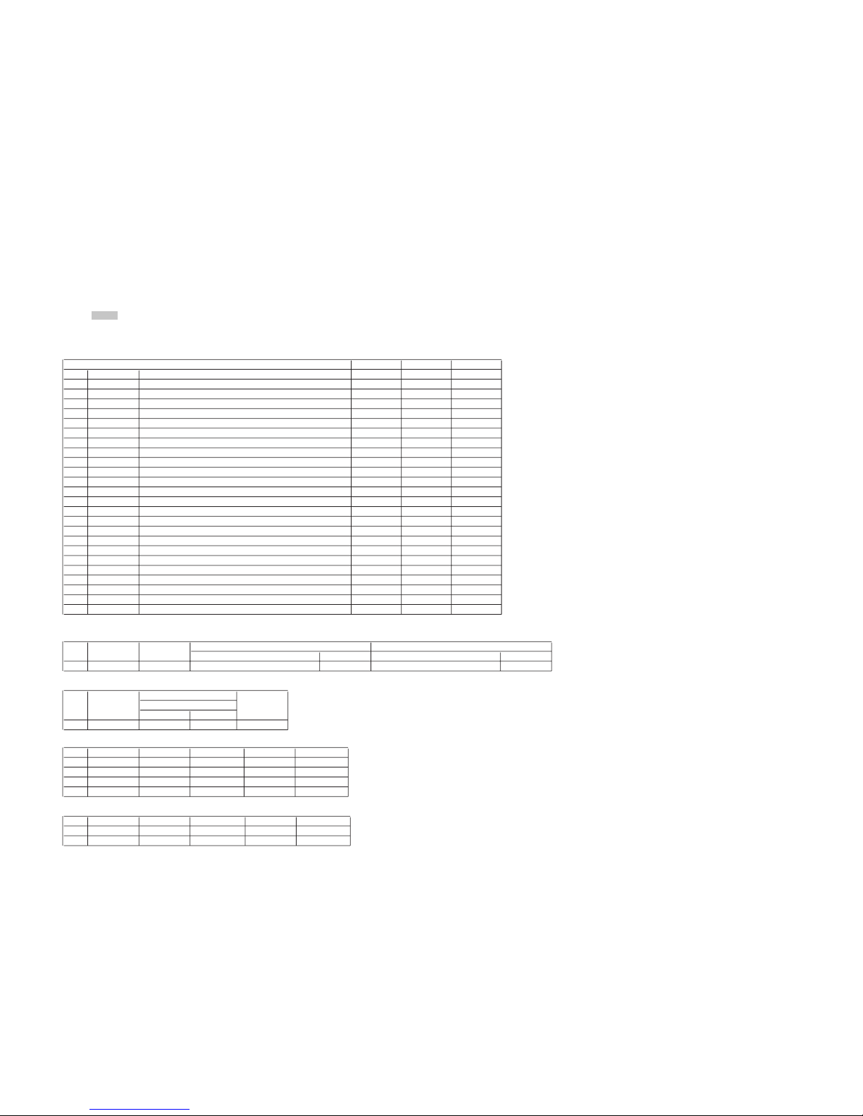
Date Version No. Description of SUP/COR
2002.10 1.0 NEW –
Change of
main text
SERVICE MANUAL
LA-1A
CHASSIS
MODEL COMMANDER DEST. CHASSIS NO.
–––––– –––––––––––– ––––– –––––––––––
KF-50XBR800 RM-Y912
KF-50XBR800 RM-Y912
KF-60XBR800 RM-Y912
KF-60XBR800 RM-Y912
US
Canadian
US
Canadian
MODEL COMMANDER DEST. CHASSIS NO.
–––––– –––––––––––– ––––– –––––––––––
KF-50XBR800/KF-60XBR800
RM-Y912
RM-Y912
LCD PROJECTION TV

SPECIFICATIONS
Projection System 3 LCD Panels, 1 lens projection system
LCD Panel 1.35 inch TFT LCD panel Approx. 3.15 million dots (1,049,088 pixels)
Projection Lens High Performance, large diameter hybrid lens F2.4
Antenna 75 ohm external terminal for VHF/UHF
Lamp UHP lamp, 100W
XL-2000U
Television System NTSC, American TV Standard
Screen Size (measured diagonally) KF-50XBR800: 50 inches, KF-60XBR800: 60 inches
Channel Coverage
VHF 2-13
UHF 14-69
CATV 1-125
Power Requirements 120V, 60 Hz
Number of Inputs/Outputs
DVI-HDTV 1 terminal 3.3 V T.M.D.S., 50 ohms
The DVI-HDTV input terminal is compliant with the EIA-861 standard and is not intended for use
with personal computers.
Video (IN) 4 1 Vp-p, 75 ohms unbalanced, sync negative
S Video (IN) 3 Y: 1 Vp-p, 75 ohms unbalanced, sync negative
C: 0.286 Vp-p (Burst signal), 75 ohms
Audio (IN) 6 500 mVrms (100% modulation)
Impedance: 47 kiloohms
AUDIO (VAR/FIX) 1 500 mVrms at the maximum volume setting (Variable)
500 mVrms (Fixed)
Impedance (output): 2 kiloohms
MONITOR OUT 1 Video: 1 Vp-p 75 ohms unbalanced, Sync negative
Audio: 500 mVrms (100% modulation)
Impedance (output): 1 kiloohms
CONTROL S (IN/OUT) 1 minijacks
Component Video Input 2 (Y, PB , PR) Y: 1.0 Vp-p, 75 ohms unbalanced, sync negative
PB: 0.7 Vp-p, 75 ohms
PR: 0.7 Vp-p, 75 ohms
RF Inputs 2
Converter 1
Speaker Output 15 W × 2
Dimensions (W × H × D) KF-50XBR800: 1,376 × 964 × 415 mm (54 1/4 × 38 × 16 3/8 inches)
KF-60XBR800: 1,618 × 1,103 × 542 mm (63 3/4 × 43 1/2 × 21 3/8 inches)
Mass KF-50XBR800: 50 kg (110 lb 4 oz), KF-60XBR800: 66 kg (145 lb 8 oz)
Power Consumption
In Use 220 W
In Standby Under 1 W
Supplied Accessories
Remote Control RM-Y912
AAA Batteries 2 supplied for remote control
Cleaning Cloth 1
Hex key wrench 1
Brackets with screws 2
Optional Accessories
KF-50XBR800/60XBR800
KRM-Y912 RM-Y912
– 2 –

KF-50XBR800/60XBR800
TV Stand SU-GW1
Lamp XL-2000U
AV Cable VMC-810/820/830 HG
Audio Cable RKC-515HG
Control S Cable RK-G69HG
Component Video Cable VMC-10/30 HG
AV Receiver STR-V555ES or equivalent
Memory Stick media 8MB (MSA-8A), 16MB (MSA-16A), 32MB (MSA-32A), 64MB (MSA-64A),
128MB (MSA-128A)
Design and specifications are subject to change without notice.
KRM-Y912 RM-Y912
– 3 –
SAFETY CHECK-OUT
e
( US model only )
KF-50XBR800/60XBR800
KRM-Y912 RM-Y912
After correcting the original service problem, perfom the follow-
ing safety checks before releasing the set to the customer:
l. Check the area of your repair for unsoldered or poorly-sol-
dered connections. Check the entire board surface for solder
splashes and bridges.
2. Check the interboard wiring to ensure that no wires are
“pinched” or contact high-wattage resistors.
3. Check that all control knobs, shields, covers, ground straps,
and mounting hardware have been replaced. Be absolutely
certain that you have replaced all the insulators.
4. Look for unauthorized replacement parts, particularly transistors, that were installed during a previous repair. Point them
out to the customer and recommend their replacement.
5. Look for parts which, through functioning, show obvious
signs of deterioration. Point them out to the customer and
recom mend their replacement.
6. Check the line cords for cracks and abrasion. Recommend
the replacement of any such line cord to the customer.
7. Check the condition of the monopole antenna (if any). Make
sure the end is not broken off, and has the plastic cap on it.
Point out the danger of impalement on a broken antenna to
the customer, and recommend the antenna’s replacement.
8. Check the B+ and HV to see they are at the values specified.
Make sure your instruments are accurate;be suspicious of
your HV meter if sets always have low HV.
9. Check the antenna temminals, metal trim, “metallized” knobs,
screws, and all other exposed metal parts for AC leakage.
Check leakage as described below.
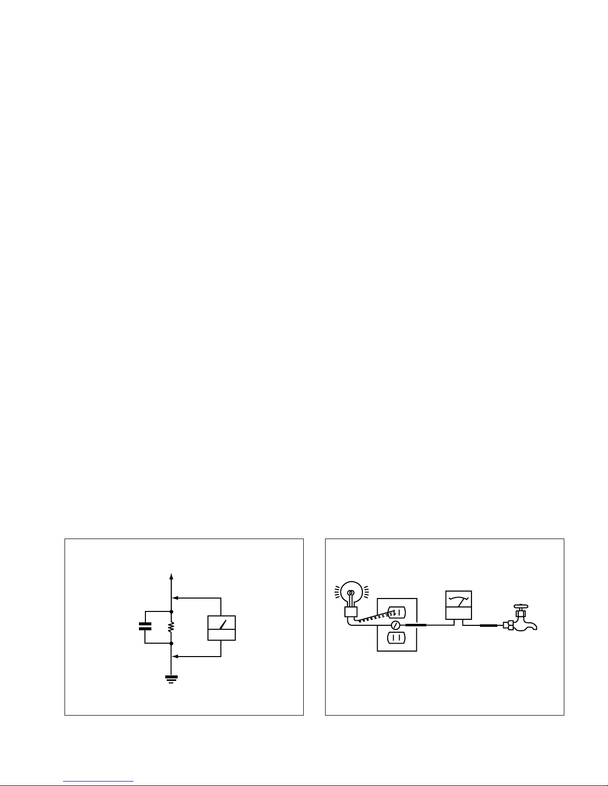
LEAKAGE TEST
The AC leakage from any exposed metal part to earth ground and
from all exposed metal parts to any exposed metal part having a
return to chassis, must not exceed 0.5mA (500 microampers) . Leakage current can be measured by any one of three methods.
1. A commercial leakage tester, such as the Simpson 229 or
RCA WT-540A. Follow the manufacturers’ instructions to
usc these instruments.
2. A battery-operated AC milliammeter. The Data Precision 245
digital multimeter is suitable for this job.
3. Measuring the voltage drop across a resistor by means of a
VOM or battery-operated AC voltmeter. The “limit” indication is 0.75V, so analog meters must have an accurate lowvoltage scale. The Simpson 250 and Sanwa SH-63Trd are
examples of a passive VOM that is suitable. NearIy all battery operated digital multimeters that have a 2V AC range
are suitable. (See Fig. A)
HOW TO FIND A GOOD EARTH GROUND
A cold-water pipe is guaranteed earth ground;the cover-plate retaining screw on most AC outlet boxes is also at earth ground. If
the retaining screw is to be used as your earth-ground, verify that it
is at ground by measuring the resistance between it and a coldwater pipe with an ohmmeter. The reading should be zero ohms. If
a cold-water pipe is not accessible, connect a 60-l00 watts trouble
light (not a neon lamp) between the hot side of the receptacle and
the retaining screw. Try both slots, if necessary, to locate the hot
side of the line, the lamp should light at normal brilliance if the
screw is at ground potential. (See Fig. B)
To Exposed Metal
Parts on Set
1.5 µ F
Fig. A. Using an AC voltmeter to check AC leakage.
1.5k Ω
Earth Ground
AC
voltmeter
(0.75V)
Trouble Light
Ohmmeter
AC Outlet Box
Cold-water Pip
Fig. B. Checking for earth ground.
– 4 –

KF-50XBR800/60XBR800
KRM-Y912 RM-Y912
SHORT CIRCUIT THE ANODE OF THE PICTURE TUBE AND THE
(CAUTION)
ANODE CAP TO THE METAL CHASSIS, CRT SHIELD, OR CARBON PAINTED ON THE CRT, AFTER REMOVING THE ANODE.
WARNING!!
AN ISOLATION TRANSFORMER SHOULD BE USED DURING
ANY SERVICE TO AVOID POSSIBLE SHOCK HAZARD, BECAUSE OF LIVE CHASSIS.
THE CHASSIS OF THIS RECElVER IS DIRECTLY CONNECTED
TO THE AC POWER LINE.
SAFETY-RELATED COMPONENT WARNING!!
COMPONENTS IDENTIFIED BY SHADING AND MARK ! ON
THE SCHEMATIC DIAGRAMS, EXPLODED VIEWS AND IN THE
PA RTS LIST ARE CRITICAL TO SAFE OPERATION. REPLACE
THESECOMPONENTS WITH SONY PARTS WHOSE PART NUMBERS APPEAR AS SHOWN IN THIS MANUAL OR IN SUPPLEMENTS PUBLISHED BY SONY. CIRCUIT ADJUSTMENTS THAT
ARE CRITICAL TO SAFEOPERATION ARE IDENTIFIED IN THIS
MANUAL. FOLLOW THESE PROCEDURES WHENEVER CRITICAL COMPONENTS ARE REPLACED OR IMPROPER OPERATION IS SUSPECTED.
APRES AVOIR DECONNECTE LE CAP DE L’ANODE, COURTCIR-
(ATTENTION)
CUITER L’ANODE DU TUBE CATHODIQUE ET CELUI DE
L’ANODE DU CAP AU CHASSIS METALLIQUE DE L’APPAREIL,
OU AU COUCHE DE CARBONE PEINTE SUR LE TUBE CATHOD-
IQUE OU AU BLINDAGE DU TUBE CATHODIQUE.
ATTENTION!!
AFIN D’EVITER TOUT RISQUE DELECTROCUTION PROVENANT D’UN CHÁSSIS SOUS TENSION, UN TRANSFORMATEUR
D’ISOLEMENT DOIT ETRE UTILISÉ LORS DE TOUT DEPANNAGE.
LE CHÁSSIS DE CE RECEPTEUR EST DIRECTEMENT RACCORDÉ Á L’ALIMENTATION SECTEUR.
ATTENTION AUX COMPOSANTS RELATIFS ÁLA
SÉCURITÉ!!
LES COMPOSANTS IDENTIFIÉS PAR UNE TRAME ET PAR UNE
MAPQUE ! SUR LES SCHÉMAS DE PRINCIPE, LES VUES EX-
PLOSÉES ET LES LISTES DE PIECES CONT D’UNEIMPORTANCE
CRITIQUE POUR LA SÉCURITÉ DU FONCTIONNEMENT. NE LES
REMPLACER QUE PAR DES COMPOSANTS SONY DONT LE
NUMÉRO DE PIÉCE EST INDIQUÉ DANS LE PRÉSENT MANUEL OU DANS DES SUPPLÉMENTS PUBLIÉS PAR SONY. LES
RÉGLAGES DE CIRCUIT DONT L’IMPORTANCE EST CRITIQUE
POUR LA SÉCURITÉ DU FONCTIONNEMENT SONT IDENTIFIES
DANS LE PRÉSENT MANUEL. SUIVRE CES PROCÉDURES
LORS DE CHAQUE REMPLACEMENT DE COMPOSANTS CRITIQUES, OU LORSQU’UN MAUVAIS FONCTIONNEMENT EST
SUSPECTÉ.
– 5 –

TABLE OF CONTENTS
KF-50XBR800/60XBR800
KRM-Y912 RM-Y912
Section Title Page
–––––– –––– ––––
1. SELF DIAGNOSIS FUNCTION ..................... 8
2. DISASSEMBLY
2-1. Rear Cover Assembly ....................................... 11
2-2. OU Bracket Removal ........................................ 11
2-3. Service Position ................................................. 11
2-4. Power Block Removal ........................................ 11
2-5. Optical Unit Block Assembly Removal ............ 12
2-6. UD Board, Terminal Board
Assembly Removal ............................................ 12
2-7. U, M, BB, BC Boards Removal ......................... 13
2-8. G Board Removal ............................................... 13
2-9. A Board Removal ............................................... 14
2-10. T Board Removal ............................................... 14
2-11. Control Panel Block Assembly Removal .......... 14
2-12. H3 Board Removal ............................................. 14
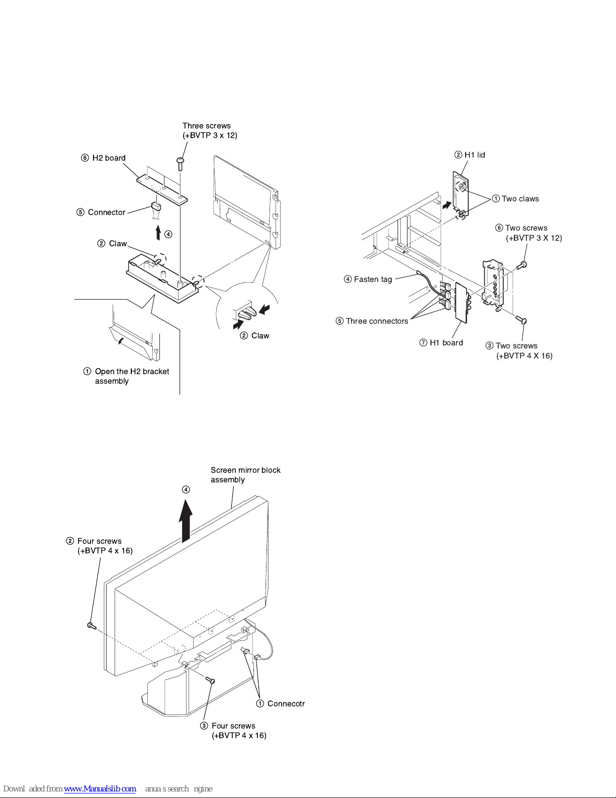
2-13. H2 Board Removal ............................................. 15
2-14. Screen Mirror Block Assembly Removal .......... 15
2-15. H1 Board Removal ............................................. 15
3. ELECTRICAL ADJUSTMENTS
3-1. Electrical Adjustment by Remote Commander .... 16
3-1-1. Method of Setting the Service Adjustment
Mode ............................................................... 16
3-1-2. Service Mode Adjustment ............................ 16
3-1-3. Memory Write Confirmation Method .......... 16
3-1-4. Adjusting Buttons and Indicator ................... 17
3-1-5. Service Mode List .......................................... 18
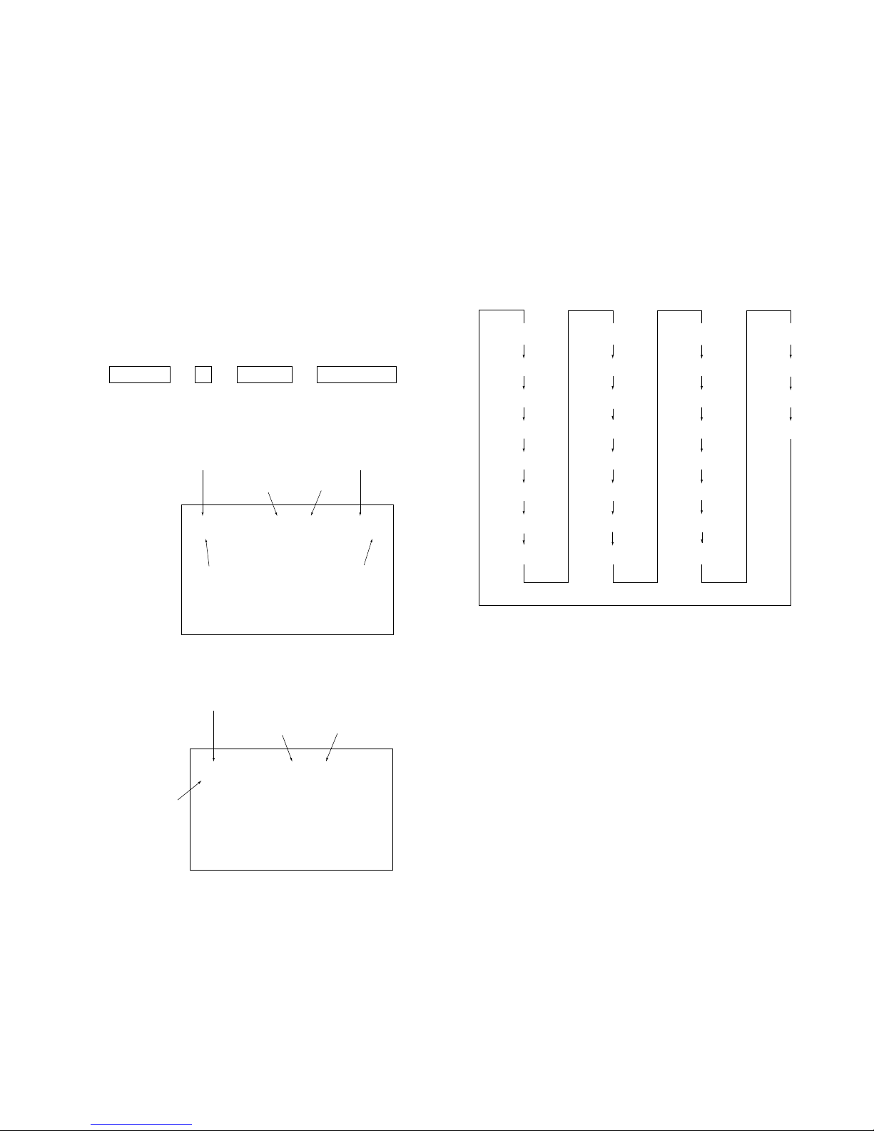
3-2. Chassis Picture Quality Adjustment ................. 65
3-2-1. White Level Adjustment ............................... 65
3-2-2. Sub Color/Sub Hue Adjustment .................... 66
3-2-3. Hi-Level/Cut-Off Adjustment ....................... 68
3-3. Vertical Stripe Adjustment ............................... 68
3-4. Sub Bright Adjustment ....................................... 69
3-5. Screen Center Adjustment ................................. 69
3-6. Favorites Adjustment ......................................... 69
Section Title Page
–––––– –––– ––––
4. DIAGRAMS
4-1. Block Diagram (1) .............................................. 70
Block Diagram (2) .............................................. 71
Block Diagram (3) .............................................. 72
Block Diagram (4) .............................................. 73
Block Diagram (5) .............................................. 74
Block Diagram (6) .............................................. 75
Block Diagram (7) .............................................. 76
Block Diagram (8) .............................................. 77
Block Diagram (9) .............................................. 78
Block Diagram (10) ............................................ 79
4-2. Frame Schematic Diagram ................................. 80
4-3. Circuit Boards Location ..................................... 81
4-4. Schematic Diagrams and Printed Wiring
Boards ................................................................. 81
(1) Schematic Diagram of A (1/4) Board ................ 82
(2) Schematic Diagram of A (2/4) Board ............... 83
(3) Schematic Diagram of A (3/4) Board ............... 84
(4) Schematic Diagram of A (4/4) Board ............... 85
(5) Schematic Diagram of BB (1/10) Board ........... 86
(6) Schematic Diagram of BB (2/10) Board ........... 87
(7) Schematic Diagram of BB (3/10) Board ........... 88
(8) Schematic Diagram of BB (4/10) Board ........... 89
(9) Schematic Diagram of BB (5/10) Board ........... 90
(10) Schematic Diagram of BB (6/10) Board ........... 91
(11) Schematic Diagram of BB (7/10) Board ........... 92
(12) Schematic Diagram of BB (8/10) Board ........... 93
(13) Schematic Diagram of BB (9/10) Board ........... 94
(14) Schematic Diagram of BB (10/10) Board ......... 95
(15) Schematic Diagram of BC (1/5) Board ............. 96
(16) Schematic Diagram of BC (2/5) Board ............. 97
(17) Schematic Diagram of BC (3/5) Board ............. 98
(18) Schematic Diagram of BC (4/5) Board ............. 99
(19) Schematic Diagram of BC (5/5) Board ............. 100
(20) Schematic Diagram of BF Board ....................... 101
(21) Schematic Diagram of BM-1C (1/3) Board ...... 102
(22) Schematic Diagram of BM-1C (2/3) Board ...... 103
(23) Schematic Diagram of BM-1C (3/3) Board ...... 104
(24) Schematic Diagram of G Board ......................... 105
(25) Schematic Diagrams of H1, H2, H3 and
T Boards ............................................................. 106
– 6 –

Section Title Page
–––––– –––– ––––
(26) Schematic Diagram of M (1/4) Board ............... 107
(27) Schematic Diagram of M (2/4) Board ............... 108
(28) Schematic Diagram of M (3/4) Board ............... 109
(29) Schematic Diagram of M (4/4) Board ............... 110
(30) Schematic Diagram of U (1/3) Board ................ 111
(31) Schematic Diagram of U (2/3) Board ................ 112
(32) Schematic Diagram of U (3/3) Board ................ 113
(33) Schematic Diagram of UD (1/2) Board ............. 114
(34) Schematic Diagram of UD (2/2) Board ............. 115
Printed Wiring Boards
• A Board ............................................................ 116
• BB Board .......................................................... 118
• BC Board .......................................................... 120
• BM-1C Board ................................................... 120
• G Board ............................................................ 122
• H1 and T Boards .............................................. 124
• H2 Board .......................................................... 125
• H3 Board .......................................................... 126
• M Board ........................................................... 127
• U Board ............................................................ 128
• UD Board ......................................................... 130
4-5 Waveforms ......................................................... 131
4-6 IC Block Diagrams ............................................. 132
4-7 Semiconductors .................................................. 134
KF-50XBR800/60XBR800
KRM-Y912 RM-Y912
5. EXPLODED VIEWS
5-1. Screen Mirror Block Section ............................ 136
5-2. Cabinet Section ................................................... 137
5-3. Main Section ....................................................... 138
5-4. Optical Unit Section ........................................... 139
6. ELECTRICAL PARTS LIST ............................ 140
– 7 –
KF-50XBR800/60XBR800
KRM-Y912 RM-Y912
SECTION 1
SELF DIAGNOSIS FUNCTION
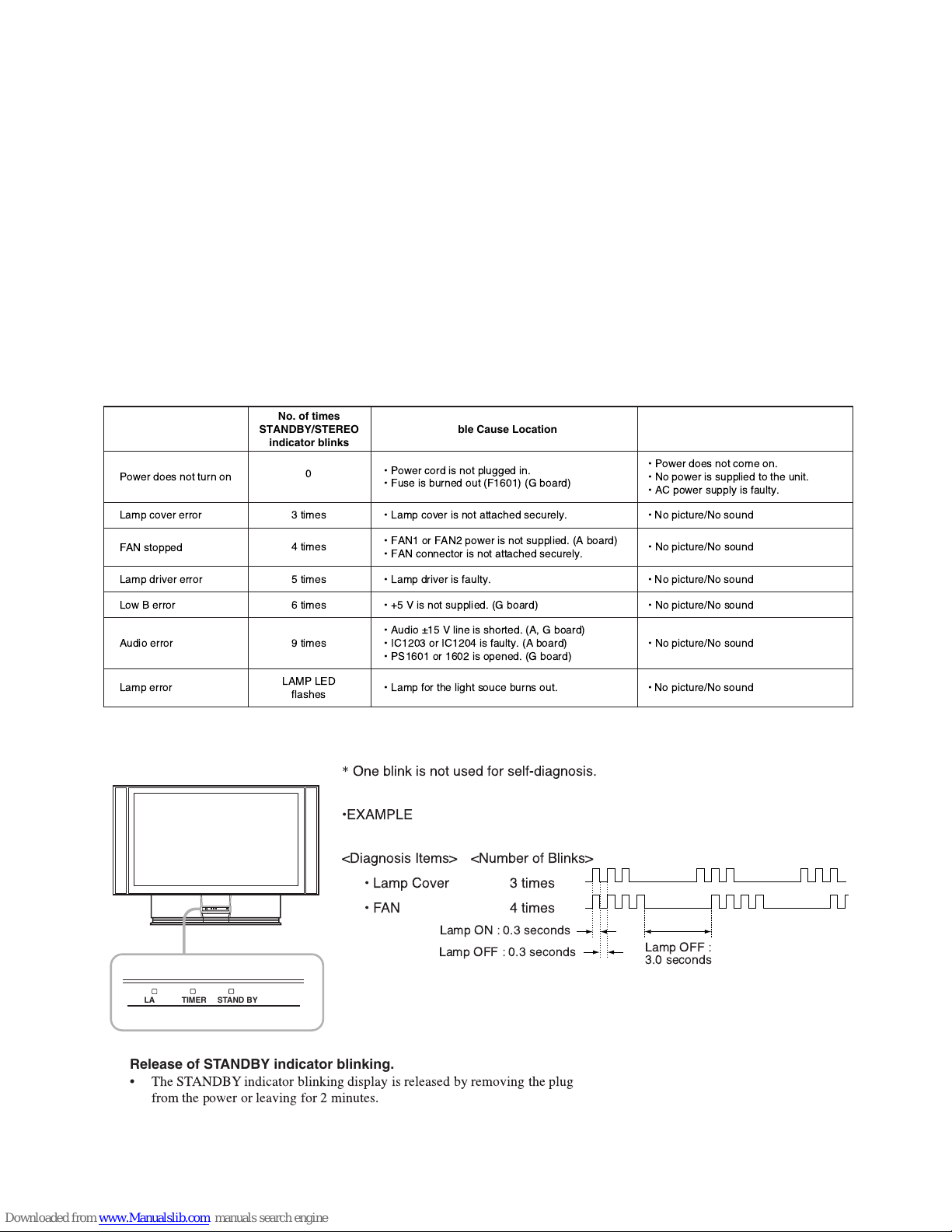
1. Summary of Self-Diagnosis Function
• This device includes a self-diagnosis function.
• In case of abnormalities, the STANDBY indicator automatically blinks. It is possible to predict the abnormality location by the number
of blinks. The Instruction Manual describes blinking of the STANDBY indicator.
• If the symptom is not reproduced sometimes in case of a malfunction, there is recording of whether a malfunction was generated or not.
Operate the remote command to confirm the matter on the screen and to predict the location of the abnormality.
2. Diagnosis Items and Prediction of Malfunction Location
• When a malfunction occurs the STANDBY indicator only blinks for one of the following diagnosis items. In case of two or more
malfunctions, the item which first occurred blinks. If the malfunctions occurred simultaneously, the item with the lower blink count
blinks first.
• The screen display displays the results regarding all the diagnosis items listed below. The display “ 0 ” means that no malfunctions
occurred.
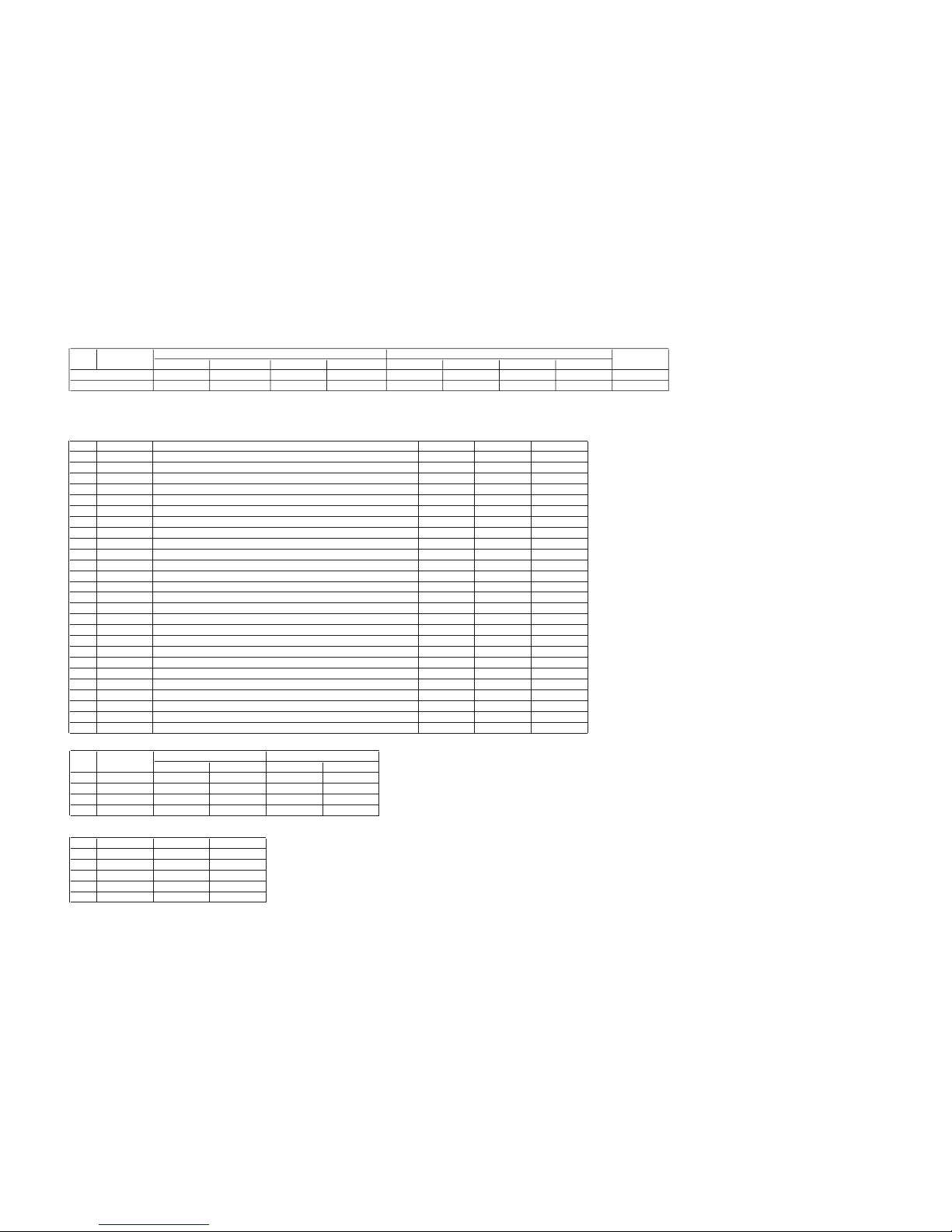
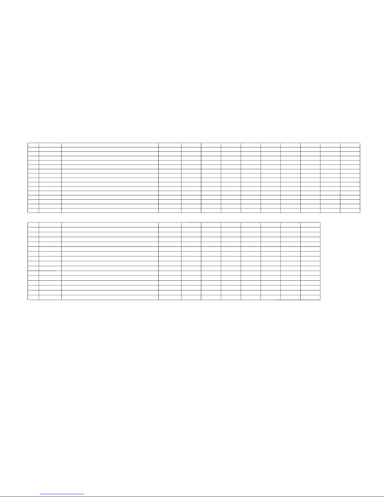
Diagnosis Item Probable Cause Location
Power does not turn on
FAN stopped
Lamp driver error ¥ Lamp driver is faulty. ¥ No picture/No sound
Audio error ¥Nopicture/No sound
Lamp error ¥ Lamp for the light souce burns out. ¥ No picture/No sound
No. of times
STANDBY/STEREO
indicator blinks
0
3 times
4 times
5 times
6 times
9 times
LAMP LED
flashes
¥ Power cord is not plugged in.
¥ Fuse is burned out (F1601) (G board)
¥ Lamp cover is not attached securely. ¥ No picture/No soundLamp cover error
¥ FAN1 or FAN2 power is not supplied. (A board)
¥ FAN connector is not attached securely.
¥+5Vis not supplied. (G board) ¥ No picture/No soundLow B error
¥ Audio ±15 V line is shorted. (A, G board)
¥ IC1203 or IC1204 is faulty. (A board)
¥ PS1601 or 1602 is opened. (G board)
Detected symptoms
¥ Power does not come on.
¥Nopower is supplied to the unit.
¥ACpower supply is faulty.
¥Nopicture/No sound
3. Blinking count display of STANDBY indicator
"
!
"# $% " '%
()
*
STAND BYTIMERLAMP
Release of STANDBY indicator blinking.
!
– 8 –
KF-50XBR800/60XBR800
Self Diagnosis
Bb
SELF DIAGNOSIS
!"!
KRM-Y912 RM-Y912
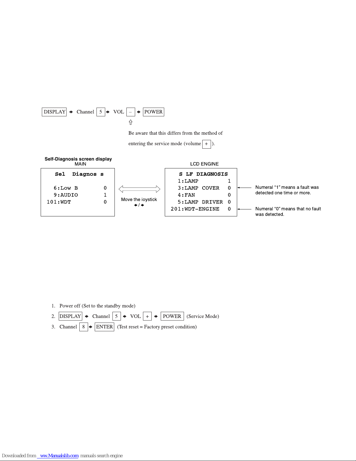
4. Self-Diagnosis screen displays
• In cases of malfunctions where it is not possible to determine the symptom such as when the power goes off occasionally or when the
screen disappears occasionally, there is a screen display on whether the malfunction occurred or not in the past (and whether the detection
circuit operated or not) in order to allow confirmation.
<Screen Display Method>
• Quickly press the remote command button in the following order from the standby state.
DISPLAYbChannel 5bVOL Ð
Self-Diagnosis screen display
b
POWER
J
Be aware that this differs from the method of
entering the service mode (volume + ).
5. Self-Diagnosis Screen Display
• The results display is not automatically cleared. In case of repairs and after repairs, check the self-diagnosis screen and be sure to return
the results display to “ 0 ”.
• If the results display is not returned to “ 0 ” it will not be possible to judge a new malfunction after completing repairs.
<Method of Clearing Results Display>
b
) *b#+,#$ , - .' / '&&
<Method of Ending Self-Diagnosis Screen>
• When ending the self-diagnosis screen completely, turn the power switch OFF on the remote commander or the main unit.
b
!
b
"#$ %&' (
– 9 –
KF-50XBR800/60XBR800
KRM-Y912 RM-Y912
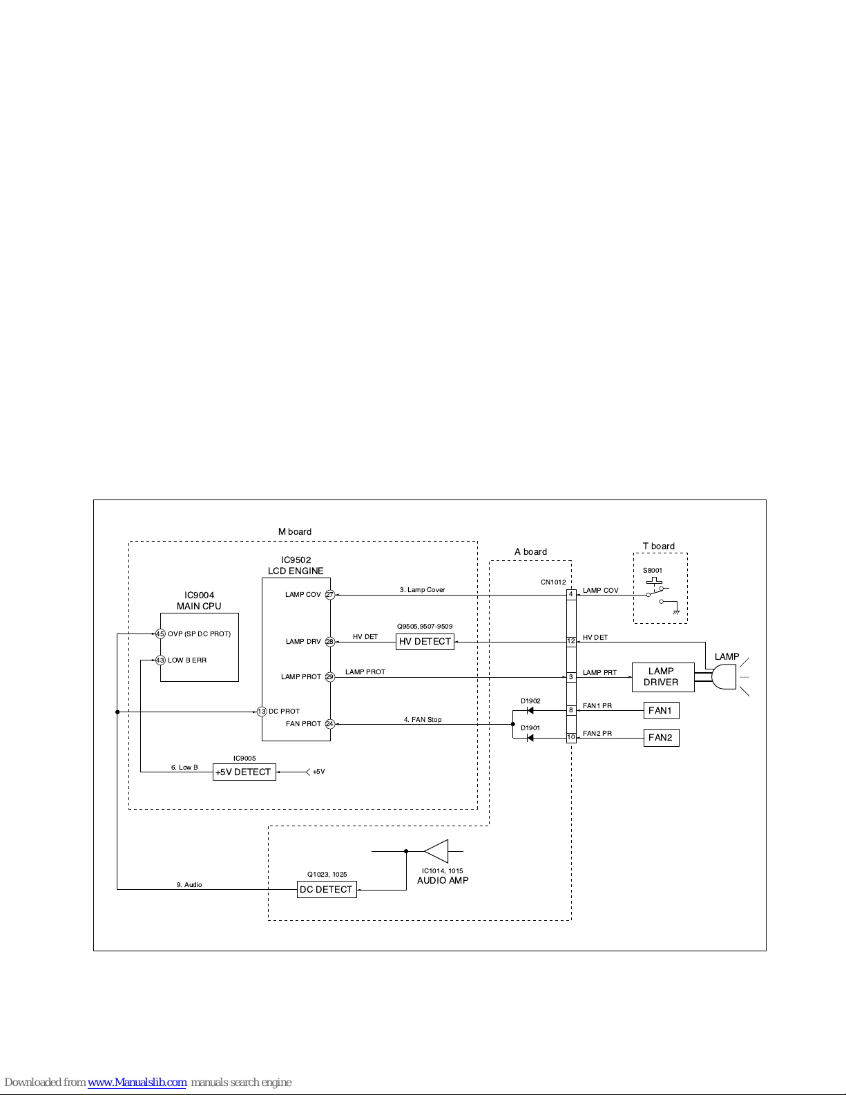
6. Self-Diagnosis function operation
3 : Lamp Cover When lamp cover SW is opened then pin 4 of CN1012 on the A board is high, LCD Engine µ-com (IC9502) detects
it and make turn off the lamp.
4 : FAN Stop When FAN1 or FAN2 is stopped then pin 8 or q; of CN1012 on the A board is high, LCD Engine µ-com (IC9502)
detects it and make turn off the lamp.
5 : Lamp Driver When lamp is not turned on then pin wl of LCD Engine µ-com (IC9502) is high, checks pin wk of LCD Engine µ-com
. If pin wk is low, it is judged no High Voltage.
6 : Low B Detect +5 V line failure.
9 : Audio When DC is appeared by audio amp failure at speaker line.
Then it is detected by MAIN µ-com (IC9004) and it turns off the main power.
LAMP : Lamp error When lamp is not turned on then pin wl of LCD Engine µ-com (IC9502) is high, checks pin wk of LCD Engine µ-com.
If pin wk is high, it is judged lamp is burned out.
Self-Diagnosis block diagram
-% .
% +,
#
/
"
$
01
!
% &' ()
01/2
!
% " *'
1
$
!
"
"
$
"
"
– 10 –
SECTION 2
KF-50XBR800/60XBR800
KRM-Y912 RM-Y912
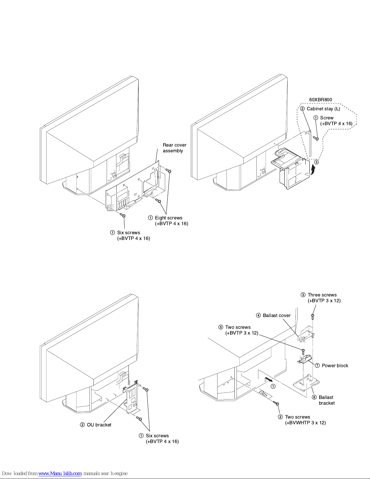
2-1. REAR COVER ASSEMBLY
1
DISASSEMBLY
2
1
2-3. SERVICE POSITION
2
1
3
2-2. OU BRACKET REMOVAL
2
OU bracket
2-4. POWER BLOCK REMOVAL
4
5
1
2
3
7
6
1
Six screws
(+BVTP 4 x 16)
– 11 –
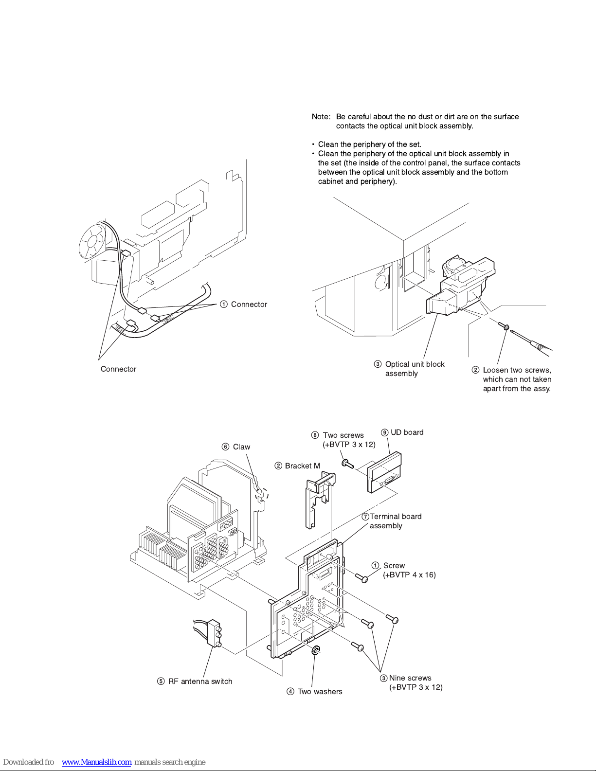
2-5. OPTICAL UNIT BLOCK ASSEMBLY REMOVAL
1
Connector
KF-50XBR800/60XBR800
KRM-Y912 RM-Y912
1
Connector
2-6. UD BOARD, TERMINAL BOARD ASSEMBLY REMOVAL
Two screws
8
6
Claw
2
Bracket M
(+BVTP3x12)
3
UD board
9
Terminal board
7
assembly
Screw
1
(+BVTP 4 x 16)
2
5
RF antenna switch
4
Twowashers
– 12 –
Nine screws
3
(+BVTP3x12)
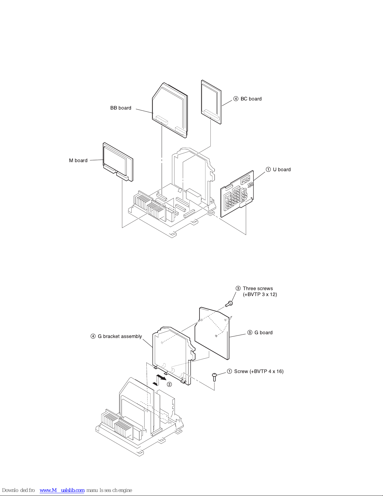
2-7. U, M, BB, BC BOARDS REMOVAL
BB board
23M board
4
BC board
1
KF-50XBR800/60XBR800
KRM-Y912 RM-Y912
U board
2-8. G BOARD REMOVAL
4
2
3
5
1
– 13 –

KF-50XBR800/60XBR800
KRM-Y912 RM-Y912
2-9. A BOARD REMOVAL
3
A board
1
Two screws
(+BVTP 3 x 12)
2
Two claws
2-11. CONTROL PANEL BLOCK ASSEMBLY
REMOVAL
2
& '
"#$ %
1
5
6
!"
"#$ %
4
&
"#$ %
3
2-10. T BOARD REMOVAL 2-12. H3 BOARD REMOVAL
3
5
2
1
4
2
1
– 14 –
KF-50XBR800/60XBR800
2
H1 lid
1
Two claws
6
Two screws
(+BVTP 3 X 12)
3
Two screws
(+BVTP 4 X 16)
4
Fasten tag
5
Three connectors
7
H1 board
KRM-Y912 RM-Y912
2-13. H2 BOARD REMOVAL
3
6
5
2
1
4
2
2-15. H1 BOARD REMOVAL
2-14. SCREEN MIRROR BLOCK ASSEMBLY
REMOVAL
4
2
1
3
– 15 –
SECTION 3
3D-COMB
2170D-2
AIDIO
2103-1
2170D-3
SNNR
2103-2
2170D-4
MID2 DRC
P-BOOST1
2170D-5
MID3 VDO
MID5 L/E
P-BOOST2
MID1 COM
MID6 CUT
P-BOOST3
2170P-3
3DNR
2170P-4
2171
2170P-1
OP
2170D-1
3506
2170P-2
DRCV
ID
ELECTRICAL ADJUSTMENTS
3-1. ELECTRICAL ADJUSTMENT BY REMOTE
COMMANDER
By using remote commander (RM-Y910K), all circuit adjust-
ments can be made.
NOTE : Test Equipment Required.
1. Pattern Generator (with component outputs)
2. Oscilloscope
3. Digital multimeter
3-1-1. Method of Setting the Service Adjustment
Mode
1. Standby mode. (Power off)
2. DISPLAY t 5 t VOL (+) t TV POWER
on the remote commander.
(Press each button within a second.)
The following service screen will appear.
KF-50XBR800/60XBR800
KRM-Y912 RM-Y912
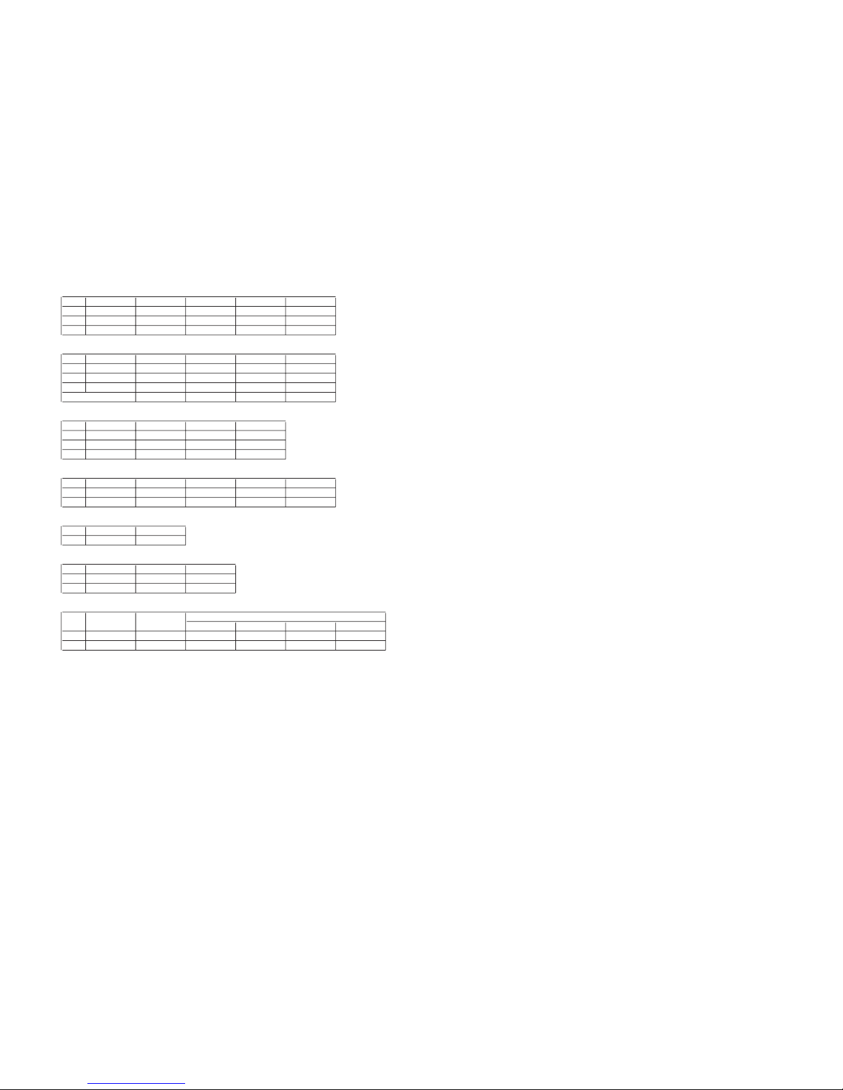
3-1-2. Service Mode Adjustment
1. The SCREEN displays the item being adjusted.
2. Press “1” or “4” on the remote commander to select the
adjustment item.
3. Press “3” or “6” on the remote commander to change the data.
4. Press “2” or “5” on the remote commander to select the category.
Every time you press “2” (Category up), Service mode
changes in the order as shown below.
Item Name
Category Name
Item No.
3D-COMB 0 0 SERVICE
NRMD TV
Item Name Input Signal
F/A FLAG: xxxxxxxx
CBA FLAG: xxxxxxxx
Category Name
L001OUT 0 0 G
OCKPN
TEMP 42DEG
LCD PJ ENGINE VER.0.026
WSL: xxx
Item No.
Data
Data
Mode
9/11
EE2F
5. If you want to recover the latest values press “-” then
“[ENTER]” to read the memory.
6. Press “[MUTING]” then “[ENTER]” to write into memory.
7. Turn power off.
Note: Press “8” then “[ENTER]” on the remote commander to
set the shipping conditions or turn set off and on to exit.
3-1-3. Memory Write Confirmation Method
1. After adjustment, turn power off with the remote commander.
2. Turn power on and set to service mode.
3. Call the adjusted items again and confirm they were adjusted.
<LCD PROJECTOR ENGINE>
– 16 –
KF-50XBR800/60XBR800
KRM-Y912 RM-Y912
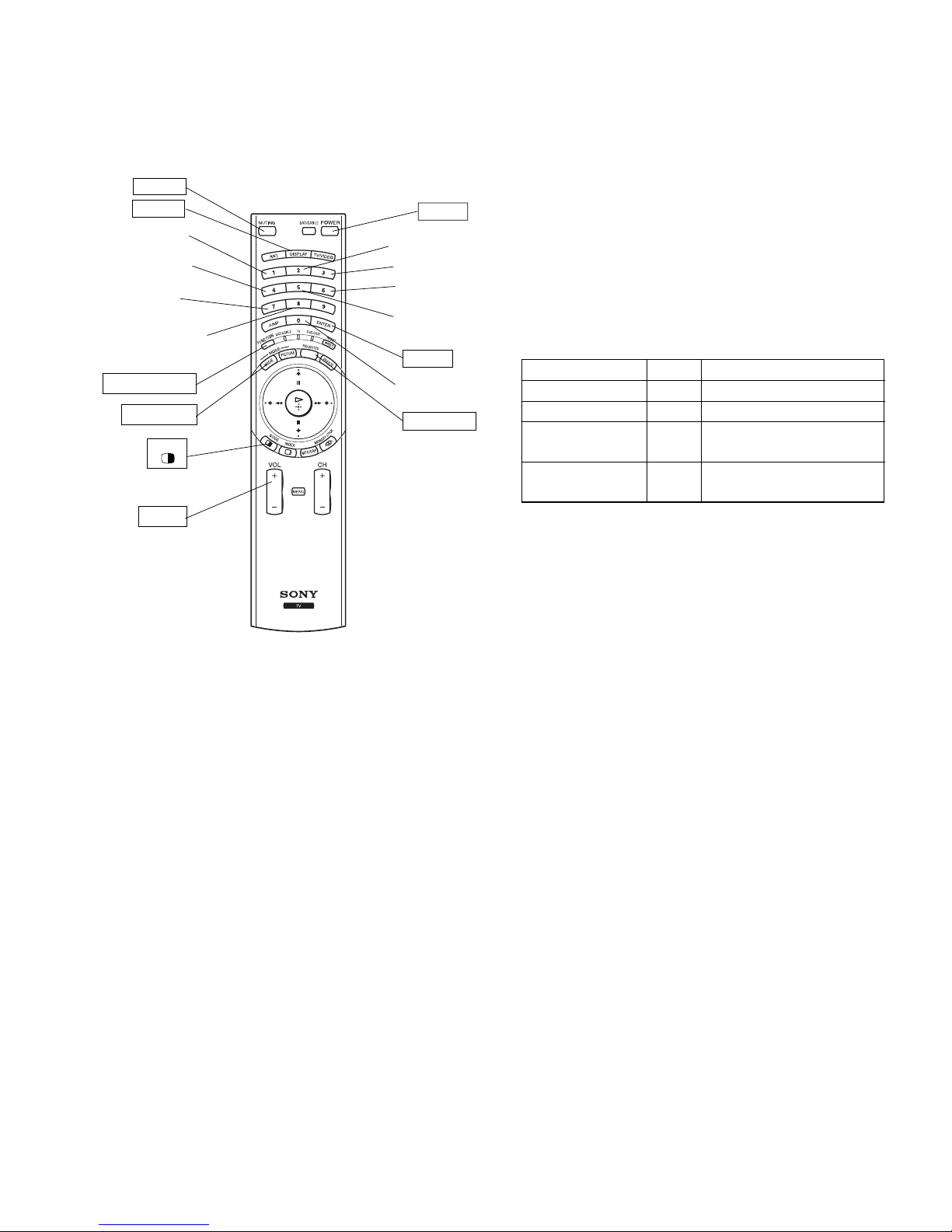
3-1-4. Adjusting Buttons and Indicator
MUTING
DISPLAY
Adjustment item
up
Adjustment item
down
Initialize data
(Not stored)
User control goes
to the standerd state
(Shipping Conditions)
PICTURE MODE
WIDE MODE
TWIN
VOL +
POWER
Adjustment category
up
Data up
Data down
Adjustment category
down
ENTER
Read data from
NVM
FAVORITES
FUNCTION OF KEYS ON COMMANDER
• 1 : Changes adjustment item. (item No. moves up)
• 4 : Changes adjustment item. (item No. moves down)
• 2 : Changes adjustment category.
(category moves up)
• 5 : Changes adjustment category.
(category moves down)
• 3 : Changes data value. (up)
• 6 : Changes data value. (down)
Commander Function
Button Mode Description
[MUTING] + [ENTER] WRITE Writes data to NVM.
- + [ENTER] READ Reads data from NVM.
8 + [ENTER] RESET Set the shipping condition.
7 + [ENTER] INT– Service data initialization.
Not stored.
(Be sure not to use usually)
RM-Y912
RM-Y912
– 17 –
– 18 –
KF-50XBR800/60XBR800
KRM-Y912 RM-Y912
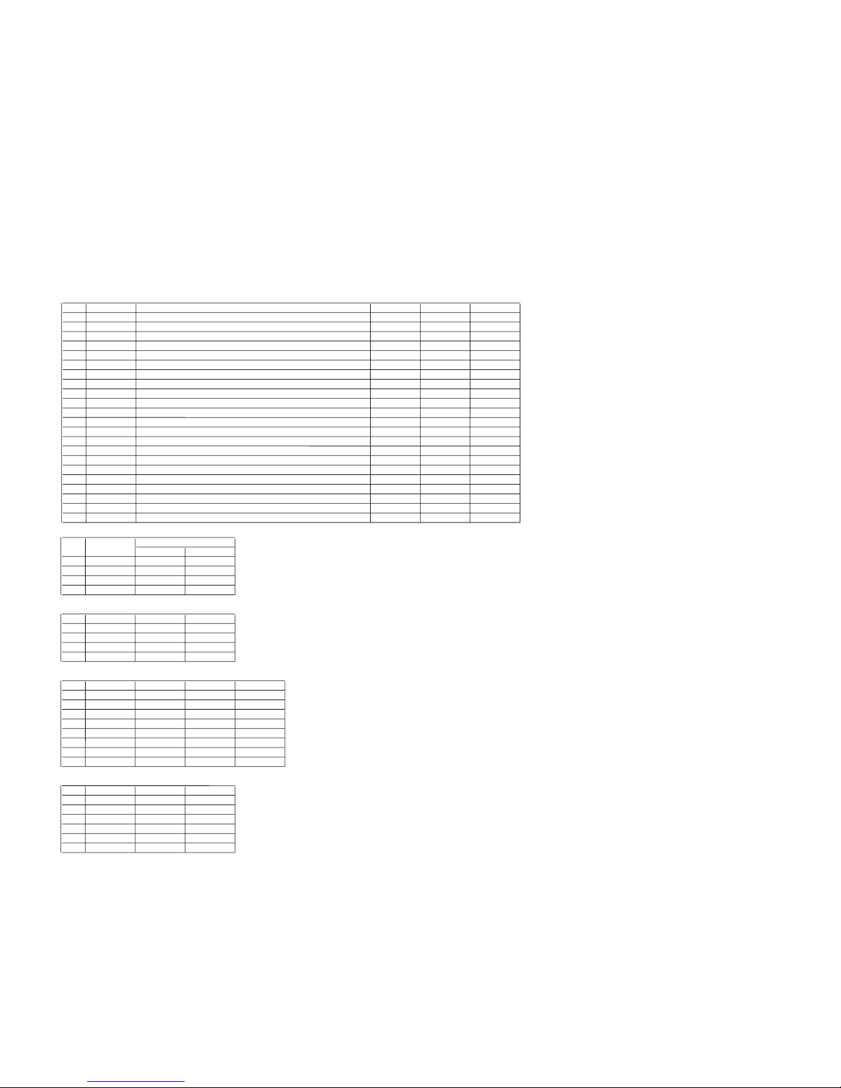
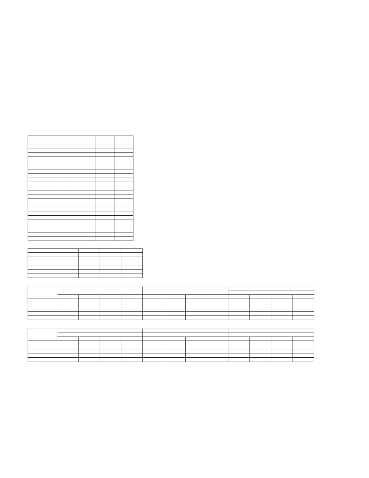
3-1-5. Service Mode List
Note: • shaded items are fixed. There is no need to change data. Others are different a little
in the sets individually. Basically, there is no need to change data, too.
3D-COMB
No. Item Function Data range Data Remarks
Table 1
0 NRMD Noise reduction mode setting 0 - 3 Table 1
1 CLKS System clock setting 0 - 3 1
STANDARD/NONSTANDERD SIGNAL Others STANDARD/NONSTANDERD SIGNAL Others
2 NSDS Selection for standard/non-standard signal processing 0 - 3 0
0 NRMD 00123
3 MSS Selection for inter-frame/inter-line processing 0 - 3 0
4 KILS Killer processing selection 0 - 3 Table 2
Table 2
5 FRZE 0
6 EXCS 1
Others
7 CDL C-signal phase with respect to the Y-signal 0 - 7 4
10
8 DYCO DY detection coring level (Y motion detedtion coring) 0 - 15 Table 3
4 KILS 2 1 1
9 DYGA DY detection gain (Y motion detection gain) 0 - 15 Table 3
10 DCCO DC detection coring level (C motion detedtion coring) 0 - 15 Table 3
11 DCGA DC detection gain (C motion detection gain) 0 - 15 Table 3
Table 3
12 WSC Amount of noise detection coring 0 - 3 1
No. Item NRMD=0 NRMD=1 NRMD=2 NRMD=3
13 WSS 0
8 DYCO 2 2 2 2
14 VAPG V aperture compensation gain 0 - 7 Table 4
9 DYGA 10 10 10 10
15 VAPI V aperture compensation convergence point 0 - 31 Table 4
10 DCCO 5 5 5 5
16 TEST Test bit (0: Normal mode, 1: Test mode) (*forbidden setting) 0, 1 0
11 DCGA 5 5 5 5
17 YPFT Y peeking filter (BPF) center frequency 0 - 3 Table 5
18 YPFG Y peeking filter (BPF) gain 0 - 15 Table 5
Table 4
19 SEDC 0
No. Item VIVID STANDARD PRO Mild
20 SEDY 1
14 VAPG 0 0 0 0
21 YHCO Y output high frequency component coring 0 - 3 1
15 VAPI 0 0 0 0
22 YHCG Y output high frequency component coring gain 0, 1 1
23 SYSP 0
24 TES2 0
No.
Item
No. Item CXA2103-1
RF/CV/YC
CV YC
RF
– 19 –
KF-50XBR800/60XBR800
KRM-Y912 RM-Y912
Table 5
VIVID STANDARD PRO Mild VIVID STANDARD PRO Mild
17 YPFT 3 3 3 3 33333
18 YPFG 7 7 7 7 88886
No. Item TWIN
RF VIDEO1-4
2103-1
No. Item Function Data range Data Remarks
Table 1
0 YLEV Y out gain 0 - 63 Table 1
1 CLEV Cb & Cr out gain 0 - 63 Table 1
RF/Video1-4 Video5-7 RF/Video1-4 Video5-7
2 SCON Sub contrast 0 - 15 Table 2
0 YLEV 25 29 42 46
3 SCOL Sub color 0 - 15 Table 2
1 CLEV 7 20 43 58
4 SHUE Sub hue 0 - 15 Table 2
20 CBOF 39 38 31 35
5 YDLY Y/C delay time 0 - 3 Table 2
21 CROF 27 34 28 35
6 SHAP Sharpness 0 - 15 Table 3
7 SHF0 Sharpness f0 selector 0 - 3 Table 3
Table 2
8 PREO Sharpness pre/over-shoot ratio 0 - 3 Table 3
No. Item RF Others
9 BPF0 Chroma band filter f0 setting 0 - 3 Table 4
2 SCON 7 9
10 BPFQ Chroma band filter Q setting 0 - 3 Table 4
3 SCOL 5 6
11 BPSW Chroma band filter on/off 0, 1 Table 2
4 SHUE 4 6
12 TRAP Y block chroma trap filter on/off 0, 1 Table 4
5 YDLY 0 0
13 LPF Y/Cb/Cr output LPF on/off 0, 1 Table 4
11 BPSW 1 0
14 AFCG AFC loop gain (PLL between H sync & H VCO) 0, 1 Table 5
15 CDMD V count down system mode selector 0 - 3 Table 5
16 SSMD H & V sync slide level setting 0 - 3 Table 5
17 HMSK Masking of macrovision signal on/off 0, 1 Table 6
18 HALI H automatic adjustment on/off 0, 1 Table 7
19 PPHA H TIM phase adjustment video 0 - 15 Table 6
20 CBOF Cb/EXT Cb offset 0 - 63 Table 1
21 CROF Cr/EXT Cr offset 0 - 63 Table 1
22 CBO2 Table 8
23 CRO2 Table 8
24 ATPD Auto-pedestal inflection point 0 - 3 Table 9
25 DCTR DC transmission ratio 0 - 3 Table 9
other Single/Mild
No. Item
– 20 –
KF-50XBR800/60XBR800
KRM-Y912 RM-Y912
Table 3
No. Item Others CV/YC V5/V6 DVI-480I
6 SHAP 6855
7 SHF0 1333
8 PREO 0300
Table 4
No. Item RF C Video S Video Component-480i
9 BPF0 3000
10 BPFQ 0000
12 TRAP 0000
13 LPF 1111
Table 5
No. Item RF Video1-4 Others
14 AFCG 1 0 0
15 CDMD 3 3 3
16 SSMD 0 0 0
Table 6
No. Item RF Video1-4 Video5-6 DVI
17 HMSK 0110
19 PPHA 7777
Table 7
No. Item RF
18 HALI 0
Table 8
No. Item DVI DVI-mild
22 CBO2 38 32
23 CRO2 34 32
Table 9
BLK0 BLK1 BLK2 BLK3
24 ATPD 00100
25 DCTR 00200
Twin
SingleNo. Item
– 21 –
KF-50XBR800/60XBR800
KRM-Y912 RM-Y912
2103-2
No. Item Function Data range Data Remarks
Table 1
0 YLEV Y out gain Table 1
1 CLEV Cb & Cr out gain Table 1
VDO DRC
2 SCON Sub contrast Table 2
0 YLEV 28 35
3 SCOL Sub color Table 2
1 CLEV 15 20
4 SHUE Sub hue Table 2
20 CBO1 36 26
5 YDLY Y/C delay time Table 2
21 CRO1 37 36
6 SHAP Sharpness Table 3
7 SHF0 Sharpness f0 selector Table 3
Table 2
8 PREO Sharpness pre/over-shoot ratio Table 3
No. Item RF Video
9 BPF0 Chroma band filter f0 setting Table 3
2 SCON 7 8
10 BPFQ Chroma band filter Q setting Table 3
3 SCOL 8 8
11 BPSW Chroma band filter on/off Table 3
4 SHUE 5 8
12 TRAP Y block chroma trap filter on/off Table 3
5 YDLY 0 0
13 LPF Y/Cb/Cr output LPF on/off Table 3
14 AFCG AFC loop gain (PLL between H sync & H VCO) Table 4
Table 3
15 CDMD V count down system mode selector Table 4
No. Item RF C Video S Video
16 SSMD H & V sync slide level setting Table 4
6 SHAP 6 6 8
17 HMSK Masking of macrovision signal on/off Table 4
7 SHF0 0 1 0
18 HALI H automatic adjustment on/off Table 4
8 PREO 3 3 3
19 PPHA H TIM phase adjustment video Table 4
9 BPF0 0 0 0
20 CBO1 Table 1
10 BPFQ 0 0 0
21 CRO1 Table 1
11 BPSW 0 0 0
12 TRAP 0 0 0
13 LPF 1 1 1
Table 4
No. Item RF Video
14 AFCG 1 0
15 CDMD 3 3
16 SSMD 0 0
17 HMSK 0 1
18 HALI 0 0
19 PPHA 7 7
RF/Video
No. Item
– 22 –
KF-50XBR800/60XBR800
KRM-Y912 RM-Y912
PIC-BOOST1
No. Item Function Data range Data Remarks
0 BSET Data table selection 0 - 15 Table 1
1 AMS Amplitude mode selection 0, 1 1
2 DEMO Demonstration mode on/off 0, 1 0
3SNSteepness correction 0 - 63 0
Table 1-1
Vivid Standard Movie Mild Vivid Standard Movie Mild Vivid Standard Movie Mild
0 BSET 2 4 6 10 5 7 8 11 1 3 9 12
Table 1-2
Vivid Standard Movie Mild Vivid Standard Movie Mild
0 BSET 1 3 9 12 0 0 0 0
Single
No. Item
No. Item
Twin
-
DVI
ComponentVideoRF
Single
PIC-BOOST2
No. Item Function Data range Data Remarks
Table 1
0 LWID Line width correction 0 - 63 Table 1
No. Item BSET:0 BSET:1 BSET:2 BSET:3 EST:4 BSET:5 BSET:6 BSET:7 BSET:8 BSET:9 BSET:10 BSET:11 BSET:12 BSET:13 BSET:14 BSET:15
1 STEP Steeness correction 0 - 63 Table 1
0 LWID 0 31 31 31 31 31 31 31 31 31 31 31 31 31 31 31
2 CRNG Coring level 0 - 63 Table 1
1 STEP 0000000000000000
3 VDC Video dependent coring on/off 0, 1 Table 1
2 CRNG 0 15 15 12 10 10 10 5 5 5 20 10 10 15 5 15
4 OSP Overrule smart peaking 0, 1 Table 1
3 VDC 0111111111111111
5 BOST Black offset compensation on/off 0, 1 Table 1
4 OSP 0010000000000000
6 ABST Adaptive black stretch 0 - 63 Table 1
5 BOST 0000000000000000
7 VGAM Variable gamma 0 - 63 Table 1
6 ABST 0000000000000000
8 NLMP Non-linearity amplifier 0 - 63 Table 1
7 VGAM 32 28 31 24 31 26 28 25 28 28 31 25 24 27 31 22
9 PKNG Peaking amplitude 0 - 63 Table 1
8 NLMP 0 26 27 21 18 24 10 28 10 10 18 28 21 22 7 18
10 CFS Color filter selection 0, 1 Table 1
9 PKNG 0 31 10 32 20 36 25 31 25 25 10 32 32 35 20 42
11 FHS Line frequency selection 0, 1 Table 1
10 CFS 0111111111111111
12 LDH Luminance determined histogram 0, 1 Table 1
11 FHS 0000000000000000
13 SNOW Snow color adjustment by green stretch 0, 1 Table 1
12 LDH 0111111111111111
14 WLB Window letterbox format 0, 1 0
13 SNOW 1111111111111111
– 23 –
KF-50XBR800/60XBR800
KRM-Y912 RM-Y912
PIC-BOOST3
No. Item Function Data range BSET:0 BSET:1 BSET:2 BSET:3 EST:4 BSET:5 BSET:6 BSET:7 BSET:8
0 CDS Color dependent sharpness on/off 0, 1111111111
1 CTI Color transient improvement on/off 0, 1000000000
2WPO White-point stretch on/off 0, 1111111111
3 DBL Blue stretch on/off 0, 1000000000
4 GBL Blue stretch gain 0, 1000000000
5 SBL Blue stretch size 0, 1000000000
6 DSK Dynamic skin tone on/off 0, 1000000000
7 ASK Dynamic skin tone angle 0, 1000000000
8WSK Dynamic skin tone width 0, 1000000000
9 SSK Dynamic skin tone size 0, 1000000000
10 DGR Green enhancement on/off 0, 1011001000
11 GGR Green enhancement gain 0, 1000000000
12 WGR Green enhancement width 0, 1000000000
13 SGR Green enhancement size 0, 1000000000
14 CDLY Chrominance delay 0 - 7 477774744
No. Item Function Data range BSET:9 BSET:10 BSET:11 BSET:12 BSET:13 BSET:14 BSET:15
0 CDS Color dependent sharpness on/off 0, 11111111
1 CTI Color transient improvement on/off 0, 10000000
2WPO White-point stretch on/off 0, 11111111
3 DBL Blue stretch on/off 0, 10000000
4 GBL Blue stretch gain 0, 10000000
5 SBL Blue stretch size 0, 10000000
6 DSK Dynamic skin tone on/off 0, 10000000
7 ASK Dynamic skin tone angle 0, 10000000
8WSK Dynamic skin tone width 0, 10000000
9 SSK Dynamic skin tone size 0, 10000000
10 DGR Green enhancement on/off 0, 10000100
11 GGR Green enhancement gain 0, 10000000
12 WGR Green enhancement width 0, 10000000
13 SGR Green enhancement size 0, 10000000
14 CDLY Chrominance delay 0 - 7 7777454

– 24 –
KF-50XBR800/60XBR800
KRM-Y912 RM-Y912
No. Item Function Data range Data Remarks
Table 1
0 RDRV Table 1
1 GDRV Table 1
2 BDRV Table 1
NOT Mild Mild NOT Mild Mild NOT Mild Mild
3 RCUT Table 1
0 RDRV 45 45 45 45 45 45 45 46 45 45 45
4 GCUT Table 1
1 GDRV 45 45 45 45 45 45 45 46 45 45 45
5 BCUT Table 1
2 BDRV 45 45 45 45 45 45 45 46 45 45 45
6 YOSW Table 2
3 RCUT 31 31 31 31 31 31 31 31 31 31 31
7 TCOF 0
4 GCUT 28 28 28 28 28 28 28 28 28 28 28
8 YOF Table 2
5 BCUT 30 30 30 30 30 30 30 30 30 30 30
9 CBOF Table 1
9 CBOF 33 33 33 33 33 33 40 38 37 33 33
10 CROF Table 1
10 CROF 32 32 32 32 32 32 39 38 37 32 32
11 SBRT 31
12 WBSW 0
13 DCOL Table 3
Table 2
No. Item RF/V1-V4 DVI OTHER
6 YOSW 1 1 0
8 YOF 0 0 7
Table 3
No. Item COOL NEUTRAL WARM
13 DCOL 0 0 0
2170P-1 (KF-50XBR800)
VIDEO 5-7
Twin MS480I
480P,VGA 720P 1080I
No. Item
other VIDEO 1-4
– 25 –
KF-50XBR800/60XBR800
KRM-Y912 RM-Y912
2170P-2 (KF-50XBR800)
No. Item Function Data range Data Remarks
Table 1
0 UPCG Table 1
No. Item Vivid Standard PRO Mild
1 UBRG Table 1
0 UPCG 63 55 31 43
2 UCOL Table 1
1 UBRG 27 31 31 31
3 UHUE Table 1
2 UCOL 35 31 31 31
4 USHP Table 1
3 UHUE 31 31 31 31
5 UTMP Table 1
4 USHP 35 33 31 25
6 UPOG Table 2
5 UTMP 2 1 1 1
7 UBOG Table 2
8 UCOF Table 2
Table 2-1
9 UHOF Table 2
10 SHOF Table 2
11 PICO Table 3
Vivid Standard PRO Mild Vivid Standard PRO Mild Vivid Standard PRO Mild
12 RGBS Table 3
6 UPOG 31 31 38 36 31 33 38 36 31 31 38 36
13 BLKB 3
7 UBOG 33 35 19 33 33 28 16 28 32 32 31 32
14 RGBL 0
8 UCOF 31 33 31 32 32 34 31 34 31 31 32 30
15 YLMT 3
9 UHOF 31 31 31 31 32 31 31 31 31 30 30 30
16 AGNG Table 4
10 SHOF 27 30 31 37 26 27 31 35 24 26 31 37
17 AKBO 0
18 CLPP 3
Table 2-2
19 CLPG 0
20 CLPS 0
21 PPAD 3
Vivid Standard PRO Mild Vivid Standard PRO Mild Vivid Standard PRO Mild
22 SYNP 0
6 UPOG 31 34 38 32 31 31 38 31 31 38 33
23 HVBT 0
7 UBOG 33 32 30 31 23 31 31 31 23 31 31 31
8 UCOF 31 31 31 31 28 28 31 28 28 28 31 28
9 UHOF 32 31 31 31 33 33
33
31 33 33 33 31 33
10 SHOF 31 33 29 31 29 33 31 34 29 33 31 34
No.
Item
Component
480p
Component
720p
Component
1080i
No. Item
RF Video
Component
480i
– 26 –
KF-50XBR800/60XBR800
KRM-Y912 RM-Y912
Table 2-3
Vivid Standard PRO Mild Vivid Standard PRO Mild
6 UPOG 31 31 38 31 31 31 38 33 31
7 UBOG 36 31 29 31 23 31 31 31 31
8 UCOF 26 29 31 28 28 28 31 28 31
9 UHOF 31 31 31 31 33 33 31 33 31
10 SHOF 31 37 31 24 29 33 31 34 31
Table 3
ON OFF
11 PICO 1 1 0
12 RGBS 0 7 0
Table 4
ON OFF
16 AGNG 2 0
Blanking
Power OFF
AGING
Twin MS1,2
VGANo. Item
No. Item
No. Item
– 27 –
KF-50XBR800/60XBR800
KRM-Y912 RM-Y912
2170P-3 (KF-50XBR800)
No. Item Function Data range Data Remarks
Table 1-1
0 SYSM Table 1
1 VMLV 7
2 VMCR Table 1
Vivid Standard PRO Mild Vivid Standard PRO Mild Vivid Standard PRO Mild
3 VMLM Table 1
0 SYSM 111111111111
4 VMF0 Table 1
2 VMCR 000000000000
5 VMDL Table 1
3 VMLM 000000000000
6 SHF0 Table 1
4 VMF0 000000000000
7 PROV Table 1
5 VMDL 000000000000
8 F1LV Table 1
6 SHF0 111111111111
9 LTLV Table 1
7 PROV 333300003333
10 LTMD Table 1
8 F1LV 000000000000
11 CTLV Table 1
9 LTLV 310221022102
12 UBOF Table 1
10 LTMD 110111011101
13 MIDE Table 3
11 CTLV 000000001100
14 VM Table 2
12 UBOF 000000000000
15 VMH Table 2
16 VMM Table 2
17 VML Table 2
18 VGAP Table 2
19 VGAS 0
20 VGAB 0
21 VGAC 0
22 VGAV 5
VIDEO 5-7
480I
VIDEO1-4RF
No. Item
– 28 –
KF-50XBR800/60XBR800
KRM-Y912 RM-Y912
Table 1-2
Vivid Standard PRO Mild Vivid Standard PRO Mild Vivid Standard PRO Mild
0 SYSM 111133333333
2 VMCR 000000000000
3 VMLM 000000000000
4 VMF0 000000000000
5 VMDL 000000000000
6 SHF0 111111111111
7 PROV 000000000000
8 F1LV 000000000000
9 LTLV 210200000000
10 LTMD 110100000000
11 CTLV 000011001100
12 UBOF 000000000000
Table 1-3
Vivid Standard PRO Mild Vivid Standard PRO Mild
0 SYSM 333322221
2 VMCR 000000000
3 VMLM 300000000
4 VMF0 000000000
5 VMDL 000000000
6 SHF0 111111111
7 PROV 333322223
8 F1LV 000000000
9 LTLV 000022000
10 LTMD 000011000
11 CTLV 000000000
12 UBOF 000000000
Table 2
No. Item Vivid Standard PRO Mild
14 VM 3001
15 VMH 15 0 13 13
16 VMM 10 0 8 8
17 VML 6044
Table 3-1
Vivid Standard PRO Mild Vivid Standard PRO Mild Vivid Standard PRO Mild
13 MIDE 750212118917161314
Table 3-2
Vivid Standard PRO Mild Vivid Standard PRO Mild Vivid Standard PRO Mild
13 MIDE 22 21 18 19 32 31 28 29 27 26 23 20
Table 3-3
Vivid Standard PRO Mild Vivid Standard PRO Mild Vivid Standard PRO Mild
13 MIDE 17 16 13 14 22 21 18 19 32 31 28 29
VIDEO 5-7
MS1, 2
VGA
Twin
No.
No. Item 480I
VIDEO5,6
other VIDEO1-4
DVI
480P
720P
VIDEO5,6
1080I
1080I
480P
720P
VIDEO5,6
480P
480I
No. Item
Item
No. Item
No. Item
DVI
VIDEO5,6
DVI
720P
– 29 –
KF-50XBR800/60XBR800
KRM-Y912 RM-Y912
Table 3-4
Vivid Standard PRO Mild Vivid Standard PRO Mild Vivid Standard PRO Mild
13 MIDE 27 26 23 20 27 26 23 20 54 54 54 54
Table 3-5
Vivid Standard PRO Mild
13 MIDE 57 56 53 54 1
No.
Item VGA
No. Item
MS2
DVI
1080I
MS1
Twin
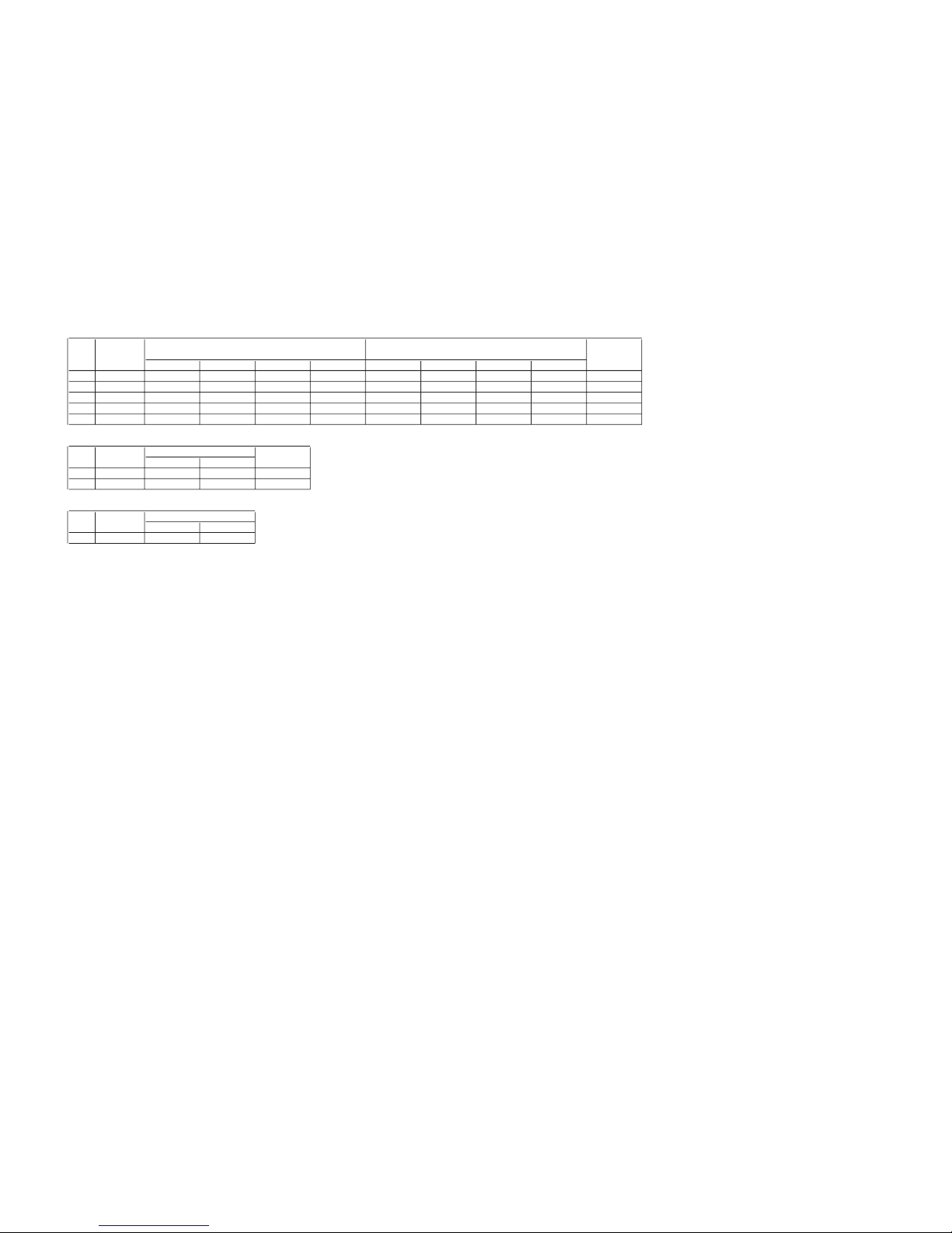
2170P-4 (KF-50XBR800)
No. Item Function Data range Data Remarks
Table 1
0 SCOL Table 1
1 SHUE Table 1
480i Others 480I Others
2 YCON Table 2
0 SCOL 31 31 29 32 30 30 31 31
3 SPIC Table 1
1 SHUE 31 31 303030313131
4 SPIO 7
3 SPIC 7 8 11 10 11 10 2 10
5 SCLO 7
6 SHUO 7
7 PIC Table 3
8BRT Table 3
9 RYR Table 4
10 RYB Table 4
11 GYR Table 4
12 GYB Table 4
13 GAMM Table 5
14 GAMS Table 6
15 GAMR Table 6
16 GAMG Table 6
17 GAMB Table 6
18 BLK Table 5
19 DCTR Table 7
20 APED Table 7
21 DSBO Table 7
22 IDSW 0
23 ABLM Table 7
24 ABLT Table 9
25 SPOF 0
26 DPSQ Table 7
27 LRGB 0
28 RROF Table 8
29 RBOF Table 8
30 GROF Table 8
31 GBOF Table 8
VIDEO5,6
No. Item
DVI
Twin MSother Video1-4
 Loading...