

Sony KF-50SX200,KF-50SX200K,KF-50SX200U Service Manual
MODEL COMMANDER DEST.
–––––––– –––––––––––––– ––––––
LE-3ASERVICE MANUAL
CHASSIS
KF-50SX200
KF-50SX200K
KF-50SX200U
RM-905
RM-905
RM-905
AEP
OIRT
UK
TV
D
R
V
C
D
V
E
REC
D
O
M
OK
PROG
MENU
TV
RM-905
LCD PROJECTION TV
– 15 –
KF-50SX200/50SX200K/50SX200U
KRM-905
SECTION 3
ELECTRICAL ADJUSTMENTS
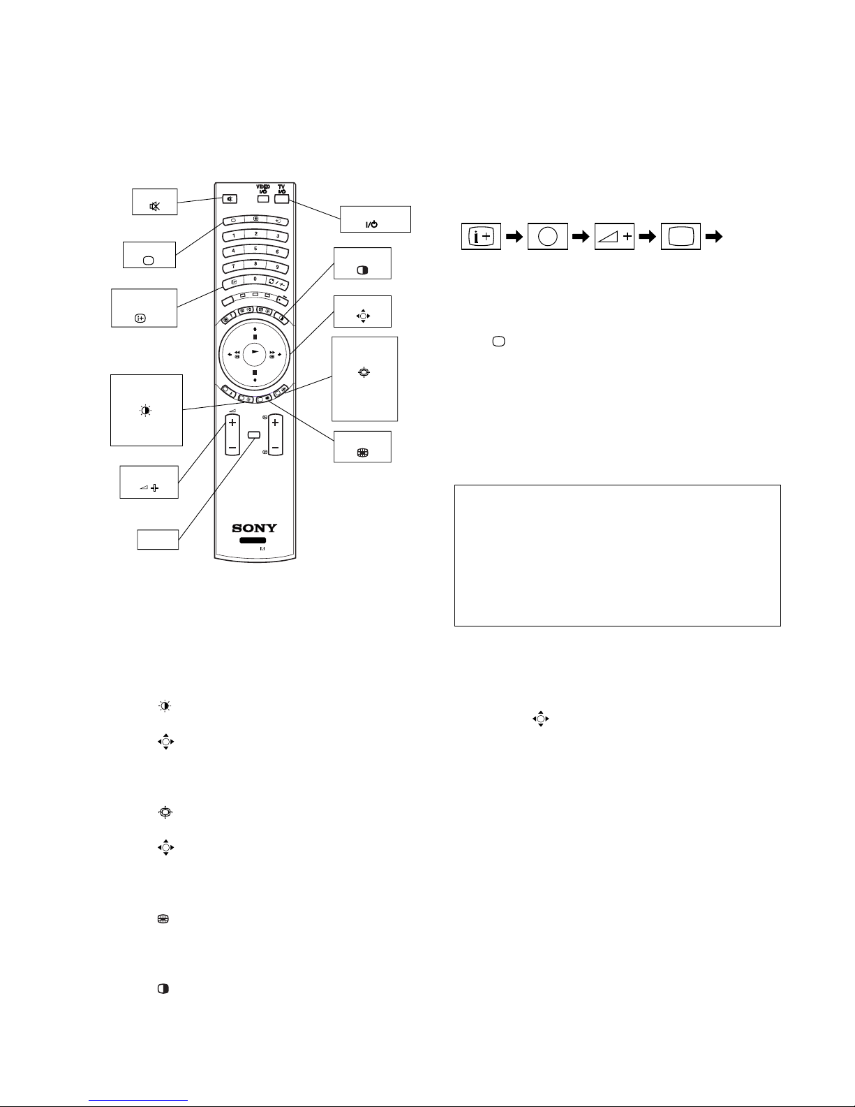
3-1. ADJUSTMENTS WITH COMMANDER
Service adjustment to this model can performed with the supplied
remote commander RM-905.
3-1-1. How to Select Each Mode
1. Selection of Mode between PAL and NTSC
PAL mode : Enter PAL signal with color burst.
NTSC mode: Enter NTSC signal with color burst. (VIDEO
input only)
2. Selection of Picture Mode
1) Press “
(GREEN)” button on the commander.
2) Press v or V key on the joystick to select picture mode and
press “ (OK)” button. At this time, normal screen comes
back. (In the TT mode, the menu is switched to the Service
menu.)
3. Selection of Screen Mode
1) Press “ (BLUE)” button on the commander.
2) Press v or V key on the joystick to select screen mode and
press “
(OK)” button. At this time, normal screen comes
back. (In the TT mode, the menu is switched to the Service
menu.)
4. Displaying Multi PIP Mode
1) Press “
(YELLOW)” button on the commander.
2) Press it once more, normal screen comes back. (In the TT
mode, the menu is switched to the Service menu.)
5. Displaying PAP Mode
1) Press “ ” button on the commander.
2) Press it once more, normal screen comes back. (In the TT
mode, the menu is switched to the Service menu.)
3-1-2. How to Enter TT Mode
1. Turn on the main power switch to place this set in standby
mode. (LED will light in red.)
2. Press the buttons on commander as follows, and the TT
mode will be selected.
“TT - -” will appear in the top right corner of the screen.
Other status information will also be displayed.
3. If “
(TV MODE)” button or “-” + “-” button is pressed,
the set exits from the TT mode and returns to normal TV mode.
3-1-3. How to Enter Service Menu
1. Select TT mode.
2. Press “MENU” button on the commander once, and normal
menu screen will appear, or press it once more, and the following service menu screen will appear.
3. Following the screen, press v or V key on the joystick to
select the desired item, and press B key to enter the selected
item.
4. Press v or V key on the joystick to change data of each item,
and press “
(OK)” button to write changed data.
(Except Projector Engine mode)
5. To return from each item, press b key on the joystick. Or, to
return to the TT mode, press the “MENU” button.
(Except Projector Engine mode)
RM-905
PROG
MENU
TV
M
O
D
E
REC
V
C
R
D
V
D
RM-905
OK
TV
MUTE
TV MODE
JOYSTICK
PAP
VOLUME +
MENU
SCREEN
MODE
Wide/Zoom/
14:9/4:3/
Smart
PICTURE
MODE
Live/Personal/
Movie/Game
ON SCREEN
DISPLAY
TV STANDBY
PIP
Enter the
“TT MODE”
5
(DIGIT 5) (VOLUME +) (TV MODE)ON SCREEN
DISPLAY
(
)
Service AE5(A)
Initialising
Reset Devices
Monitoring
Device Register Setting
Special Adjustment
Select : v V Next menu : B

– 16 –
KF-50SX200/50SX200K/50SX200U
KRM-905
Model Setting
1 KV-29FX60
2 KV-29FC60
3 KV-29FS60
4 KV-28FX60
5 KV-32FX60
6 KV-32FS60
7 KV-28FC60
8 KV-32FC60
9 KP-44PS3
10 KP-51PS3
11 KF-50SX200
12 KDP-44NX1U
13 KDP-51NX1U
14 KP-48PS1/PS2
15 KP-53PS1/PS2
16 KP-61PS1/PS2
17 KP-44PS2
18 KP-51PS2
19 KF-50SX100
BLACK = No conformity
GREEN = Compatible Model
RED = Conformity for all data
Select : v V Last menu : b Set Model : B
• Initialising b Model Setting
• Initialising b Basic Setting
Basic Setting
No Descr. Min Max Data
1 Sys. B/G OFF ON ON
2 Sys. D/K OFF ON ON
3 Sys. L OFF ON ON
4 Sys. I (UK) OFF ON ON
5 Sys. I (IRL) OFF ON OFF
6 TXT Nat.Option 1 4 3
7 Simple PAT OFF ON ON
8 16 : 9 CRT OFF ON ON
9 Sub-Woofer OFF ON ON
10 Auto Stand-By OFF ON ON
11 Comb-Filter OFF ON ON
12 Auto YC det OFF ON ON
13 Auto Comb det OFF ON ON
14 AV2 Available OFF ON ON
15 AV3 Available OFF ON ON
16 AV4 Available OFF ON ON
17 AV3 Front&Rear OFF ON OFF
18 SECAM Tape OFF ON ON
19 AV1 SoundMute OFF ON OFF
Select : v V Last menu : b Enter Item : B
• Initialising b Feature Setting
Feature Setting
No Descr. Min Max Data
1 PAP OFF ON ON
2 PAT OFF ON ON
3 INDEX OFF ON ON
4 EPG OFF ON ON
5 Full EPG OFF ON ON
6 PictBoostBypass OFF ON OFF
Select : v V Last menu : b Enter Item : B
Reset Devices
Colour Decoder 1
Colour Decoder 2
Audio/Video Switch
MID-X
External PLL MID-X
Gate Array Chip
AutoWide
Sound
Picture Booster
MCP
Analog NR
Select : v V Last menu : b Reset Dev. : B
• Reset Devices
3-1-4. Screen Display for Service Menu
If each item of service menu is selected, the following screen is
displayed.
Initialising
Model Setting
Destination Setting
Basic Setting
Feature Setting
Select : v V Next menu : B
• Initialising
Destination Setting
Multi
A
B
D
E
K
R
U
GA
BLACK = No conformity
GREEN = Compatible Destination
RED = Conformity for all data
Select : v V Last menu : b Set Dest. : B
• Initialising b Destination Setting

– 17 –
KF-50SX200/50SX200K/50SX200U
KRM-905
Device Register Setting
Colour Decoder 1
Colour Decoder 2
Audio/Video Switch
MID-X
External PLL MID-X
Gate Array Chip
Autowide
Sound
Projector Engine
Picture Booster
MCP
Analog NR
Select : v V Next menu : B
• Device Register Setting
Monitoring
Device Status Monitor
Error Monitor
LCD-Engine error menu
Production Monitor
NVM Monitor
Format Monitor
CNI Monitor
Select : v V Next menu : B
• Monitoring
• Device Register Setting b Colour Decoder 1
Colour Decoder 1
No Descr. Def. Min Max Data
1 TINT 31 0 63 31
2 SUB COLOUR 7 0 15 7
3 SUB CONTR 7 0 15 7
4 SHARP GAIN 8 0 15 8
5 Y-OUT LEV. 35 0 63 35
6 C-OUT LEV. 45 0 63 45
7 Y-DL 8 0 10 8
8 Cr OFF.1 7 0 15 7
9 Cb OFF.1 7 0 15 7
10 Cr OFF.2 7 0 15 7
11 Cb OFF.2 7 0 15 7
12 V CD FREQ 3 0 7 3
13 V CD MODE 1 0 3 1
14 MVM OFF OFF ON OFF
15 S R-Y ADJ 7 0 15 7
16 S B-Y ADJ 2 0 15 2
17 BELL/HPF 2 0 3 2
18 BELL F0 OFF OFF ON OFF
19 S GP 0 0 3 0
Select : v V Last menu : b Enter Item : B
• Device Register Setting b Colour Decoder 2
Colour Decoder 2
No Descr. Def. Min Max Data
1 TINT 31 0 63 31
2 SUB COLOUR 7 0 15 7
3 SUB CONTR 7 0 15 7
4 SHARP GAIN 8 0 15 8
5 Y-OUT LEV. 35 0 63 35
6 C-OUT LEV. 45 0 63 45
7 Y-DL 8 0 10 8
8 Cr OFF. 1 7 0 15 7
9 Cb OFF. 1 7 0 15 7
10 Cr OFF. 2 7 0 15 7
11 Cb OFF. 2 7 0 15 7
12 V CD FREQ 3 0 7 3
13 V CD MODE 1 0 3 1
14 MVM OFF OFF ON OFF
15 S R-Y ADJ 7 0 15 7
16 S B-Y ADJ 2 0 15 2
17 BELL/HPF 2 0 3 2
18 BELL F0 OFF OFF ON OFF
19 S GP 0 0 3 0
Select : v V Last menu : b Enter Item : B
Audio/Video Switch
No Descr. Def. Min Max Data
• Device Register Setting b MID-X
MID-X
No Descr. Def. Min Max Data
1 M H POS 8 –31 31 8
2 S H POS 2 –8 8 2
3 D YS SEL 1 0 3 1
4 D YS DELAY 7 0 7 7
5 D SYNC MOD ON OFF ON ON
6 Text Sharp OFF OFF ON OFF
Select : v V Last menu : b Enter Item : B
• Device Register Setting b Audio/Video Switch
 Loading...