

Sony KF-50SX200 Service manual
MODEL COMMANDER DEST.
–––––––– –––––––––––––– ––––––
LE-3ASERVICE MANUAL
CHASSIS
KF-50SX200
KF-50SX200K
KF-50SX200U
RM-905
RM-905
RM-905
AEP
OIRT
UK
TV
DVD
VCR
E
REC
D
O
M
OK
PROG
MENU
TV
RM-905
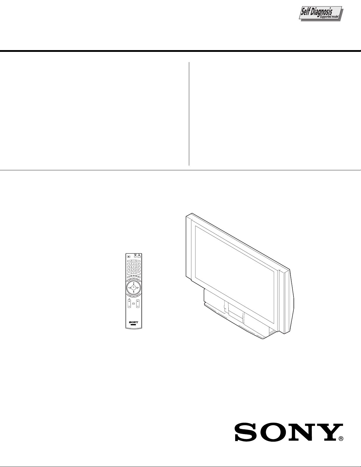
LCD PROJECTION TV

SPECIFICATIONS
KF-50SX200/50SX200K/50SX200U
KRM-905
TV system
B/G/H, D/K, I, L
Colour system
PAL, SECAM
NTSC 3.58, 4.43 (only Video In)
Channel coverage
VHF: E2-E12
UHF: E21-E69
CATV: S1-S20
HYPER: S21-S41
D/K: R1-R12, R21-R69
I: UHF B21-B69
L: F2-F10, B-Q, F21-F69
Projected picture size
50 inches (approx. 127 cm measured diagonally).
Rear Terminals
• Centre speaker input terminals (2
• (L, R) audio outputs (phono jacks)
• :1/ 1 21-pin Euro connector (CENELEC
• :2/ 2 21-pin Euro connector (CENELEC
• :3/q 3 21-pin Euro connector (CENELEC
Front Terminals
• q 4 S video input - 4 pin DIN
•
• 4 audio inputs - phono jacks
• Headphones jack - minijack stereo
C
standard) including audio/video
(SMARTLINK)
… 4 video input - phono jack
terminals)
standard) including TV audio/video
input, RGB input, TV audio/video
output.
input, RGB input, audio/video
output (monitor out).
standard) including audio/video
input, S video input, selectable
audio/video output and Smartlink
interface.
Sound output
2 x 20 W (music power)
2 x 15 W (RMS)
Centre SP input
30 W (RMS) (using as the centre speaker)
Power consumption
210 W
Standby Power consumption
≤ 1 W
Dimensions (w x h x d)
Approx. 1376 x 898 x 384 mm
Weight
Approx. 43 kg
Accessories supplied
1 Remote Control (RM-905)
2 Batteries (IEC designated, AAA size)
1 Hexagon key
2 Brackets
2 Screws
1 Cleaning Cloth
Other features
• Digital Comb filter (High resolution)
• TELETEXT, Fastext, TOPtext (2000 page TEXT memory)
• NexTView
• NICAM
• Sleep Timer
• Smartlink
• Noise Reduction
• Graphic Equaliser
• Personal ID
• Dolby Virtual
• BBE
Design and specifications are subject to change without notice.
Ecological Paper - Totally Chlorine Free
– 2 –

TABLE OF CONTENTS
1. SELF DIAGNOSIS FUNCTION
1-1. LE-3A Self Diagnostic Software ....................... 5
1-2. Error Detection Monitor..................................... 6
1-2-1. Error Monitor Menu....................................... 6
1-2-2. Error Reader Display ..................................... 7
2. DISASSEMBLY
2-1. Rear Cover Assembly ....................................... 8
2-2. Service Position ................................................. 8
2-3. OU Bracket Removal ........................................ 8
2-4. Duct Block Assembly ....................................... 8
2-5. Power Block ...................................................... 9
2-6. Optical Unit Block Assembly ............................ 9
2-7. J Board Removal ................................................ 10
2-8. M, BD, S, N Boards Removal............................ 10
2-9. T Board Removal ............................................... 10
2-10. A Board Removal............................................... 10
2-11. G Block Assembly Removal.............................. 11
2-12. G Board Removal............................................... 11
2-13. Front Covers Removal ....................................... 11
2-14. Control Panel Block Assembly Removal .......... 11
2-15. H4 Board Removal............................................. 12
2-16. H2 Board Removal............................................. 12
2-17. Screen Mirror Block Assembly ......................... 12
2-18. Mirror Cover Block Assembly Removal........... 12
2-19. Contrast Screen, Diffusion Plates Removal ...... 13
2-20. Squawker Block Assemblies, Woofer Block
Assembly Removal ............................................ 13
2-21. Speakers Removal .............................................. 14
2-22. Mirror Removal.................................................. 14
2-23. H1 Board Removal............................................. 14
3. ELECTRICAL ADJUSTMENTS
3-1. Adjustment With Commander ........................... 15
3-1-1. How to Select Each Mode ............................. 15
3-1-2. How to Enter TT Mode ................................. 15
3-1-3. How to Enter Service Menu ......................... 15
3-1-4. Screen Display for Service Menu ................. 16
3-1-5. Service List (Projector Engine) .................... 20
3-2. LCD Projector Engine ....................................... 27
3-2-1. Operation Method for Projector
Engine Mode ................................................. 27
3-3. Sub Colour Adjustment ..................................... 27
3-4. RGB Output Level Adjustment ......................... 28
3-5. Vertical Stripe Adjustment................................. 28
3-6. Sub Bright Adjustment....................................... 29
3-7. Screen Center Adjustment ................................. 29
3-7-1. Horizontal center adjustment ........................ 29
3-7-2. Vertical center adjustment ............................ 29
3-8. Test-Test Mode................................................... 29
KF-50SX200/50SX200K/50SX200U
KRM-905
Section Title PageSection Title Page
4. DIAGRAMS
4-1. Block Diagram (1).............................................. 31
Block Diagram (2).............................................. 32
Block Diagram (3).............................................. 33
Block Diagram (4).............................................. 34
Block Diagram (5).............................................. 35
Block Diagram (6).............................................. 36
Block Diagram (7).............................................. 37
Block Diagram (8).............................................. 38
4-2. Frame Schematic Diagram................................. 39
4-3. Circuit Boards Location ..................................... 40
4-4. Schematic Diagrams and Printed Wiring
Boards ................................................................. 40
(1) Schematic Diagram of A (1/4) Board ................ 41
(2) Schematic Diagram of A (2/4) Board ............... 42
(3) Schematic Diagram of A (3/4) Board ............... 43
(4) Schematic Diagram of A (4/4) Board ................ 44
(5) Schematic Diagram of BB (1/6) Board ............. 45
(6) Schematic Diagram of BB (2/6) Board ............. 46
(7) Schematic Diagram of BB (3/6) Board ............. 47
(8) Schematic Diagram of BB (4/6) Board ............. 48
(9) Schematic Diagram of BB (5/6) Board ............. 49
(10) Schematic Diagram of BB (6/6) Board ............. 50
(11) Schematic Diagram of G Board ......................... 51
(12) Schematic Diagrams of H1, H2, H4
and T Boards ...................................................... 52
(13) Schematic Diagram of J (1/5) Board ................. 53
(14) Schematic Diagram of J (2/5) Board ................. 54
(15) Schematic Diagram of J (3/5) Board ................. 55
(16) Schematic Diagram of J (4/5) Board ................. 56
(17) Schematic Diagram of J (5/5) Board ................. 57
(18) Schematic Diagram of M (1/3) Board ............... 58
(19) Schematic Diagram of M (2/3) Board ............... 59
(20) Schematic Diagram of M (3/3) Board ............... 60
(21) Schematic Diagram of N Board ......................... 61
(22) Schematic Diagram of S Board.......................... 62
Printed Wiring Boards
• A Board ............................................................ 63
• BB Board.......................................................... 65
• G Board ............................................................ 67
• H1, H2, H4 and T Boards ................................ 69
• J Board ............................................................. 70
• M Board ........................................................... 71
• N Board ............................................................ 72
• S Board............................................................. 73
4-5 Waveforms ......................................................... 74
4-6 IC Block Diagrams............................................. 76
4-7 Semiconductors .................................................. 77
– 3 –

Section Title Page
5. EXPLODED VIEWS
5-1. Mirror Section ................................................... 79
5-2. Screen Section ................................................... 80
5-3. Cabinet Section................................................... 81
5-4. Chassis Section................................................... 82
5-5. Optical Unit Section ........................................... 83
6. ELECTRICAL PARTS LIST ............................ 84
KF-50SX200/50SX200K/50SX200U
KRM-905
SAFETY-RELATED COMPONENT WARNING!!
COMPONENTS IDENTIFIED BY SHADING AND MARK
! ON THE SCHEMATIC DIAGRAMS, EXPLODED
VIEWS AND IN THE PARTS LIST ARE CRITICAL TO
SAFE OPERATION. REPLACE THESE COMPONENTS
WITH SONY PARTS WHOSE PART NUMBERS APPEAR AS SHOWN IN THIS MANUAL OR IN SUPPLEMENTS PUBLISHED BY SONY.
– 4 –
KF-50SX200/50SX200K/50SX200U
SECTION 1
KRM-905
SELF DIAGNOSIS FUNCTION
1-1. LE-3A SELF DIAGNOSTIC SOFTWARE
The identification of errors within the LE-3A chassis is triggered in one of two ways : - 1: Busy or 2: Device failure to respond to IIC.
In the event of one of these situations arising the software will first try to release the bus if busy (Failure to do so will report with
continuous flashing LED) and then communicate with each device in turn to establish if a device is faulty. If a device is found to be
faulty the relevant device number will be displayed through the LED (Series of flashes which must be counted) See table 1., non fatal
errors are reported using this method.
Diagnostic Item
Description
Power does not turn on Does not light
SET 5V Dowin 2 times
No. of times Standby
LED Flashes
ERROR STBY LED ERROR COUNT
No error 00
Not allowed (may be confused with Sircs response flash) 01
SET 5V Down 02
Lamp Cover error 03
Fan error 04
Lamp Driver error 05
Not used 06
Speaker Protection 07
General IIC Line 0 error 08
MEGATEXT (IC9502) 09
NVM (IC9108) 10
Main colour decoder (IC8301) 11
MCP (IC701) 14
Multi sound processor (IC4702) 15
Auto Wide (IC8700) 16
External RAM (IC9107) 17
Lamp error Lamp LED continually on
Probable cause Location
Power cord is not plugged in
Fuse is Burned out
Q1606, 1607 Power FET is shorted Power does not come on
(G Board) Load on power line has shorted
Detected Symptoms
Power does not come on
No power is supplied to the TV
AC power supply is faulty
Flash Timing Example : e.g. error number 3
ON
OFF OFF
ON ONStandby LED
– 5 –

KF-50SX200/50SX200K/50SX200U
1-2. ERROR DETECTION MONITOR
Device acknowledge is used to check IIC errors.
Each device is checked three times, if there is no acknowledge after every attempt, it will be regarded as an error.
There are three step to check errors.
1. IIC line 0
If all devices except the NVM have errors, IIC line 0 error is displayed.
2. Each device check
if IIC line error and board error are not detected then the device with an error is displayed.
The detected errors can be displayed as follows:
1. Error Monitor Menu
2. Error Reader
1-2-1.Error Monitor Menu
The error monitor menu is displayed by selecting Service mode : Monitoring. The following menu will be displayed:
KRM-905
Error Monitor
Ignore Errors OFF
1
Operating Time :
Stored Errors :
1. J-B MSP3411G
2. B3-B CXA2101 MCP
3. J-B CXA2123 Main Col Dec
4. Error Code Not Valid
5. Error Code Not Valid
Current Error :
Start Error Sequence
Error Monitor
1 LAMP : 0
5 LAMP DRIVER : 0
4 FAM : 0
3 LAMP COVER : 1
WDT-E : 0
000021 h 40 min
ON ON
Error Monitor
LCD-Engine error menu
– 6 –
KF-50SX200/50SX200K/50SX200U
KRM-905
1-2-2. Error Reader Display
The error reader display is connected to the service connector to read actual error codes. The part number for the error reader display is
S-188-900-10.
Once an error has been detected it will then be displayed on the two digit error reader. The errors displayed refer to the following table:
Send Data to Error Reader
Error Code Data High Data Low Error Type Function
00 00h – f0h no device
Gen. IIC Error
00 01h f0h 01h IIC 0 line
00 02h f0h 02h IIC 1 line not used
Device Error
A Board
01 01h f1h 01h CXA1875 Port Expander
01 02h f1h 02h TU1301 Main Tuner
01 03h f1h 03h TU1302 Sub Tuner
BB Board
04 01h f4h 01h CXD9509 MID-X
BB Board
06 01h f6h 01h CXA2101 MCP
J Board
04 04h f4h 04h TDA9178 Picture Booster
07 03h f7h 03h CXA2123 Sub Colour
07 04h f7h 04h CXA2123 Main Colour
07 0Ah f7h 0Ah CXA2149 AV SW
S Board
07 08h f7h 08h MSP3411G Sound Proc
M Board
08 01h f8h 01h M24C32 NVM
– 7 –
KF-50SX200/50SX200K/50SX200U
SECTION 2
DISASSEMBLY
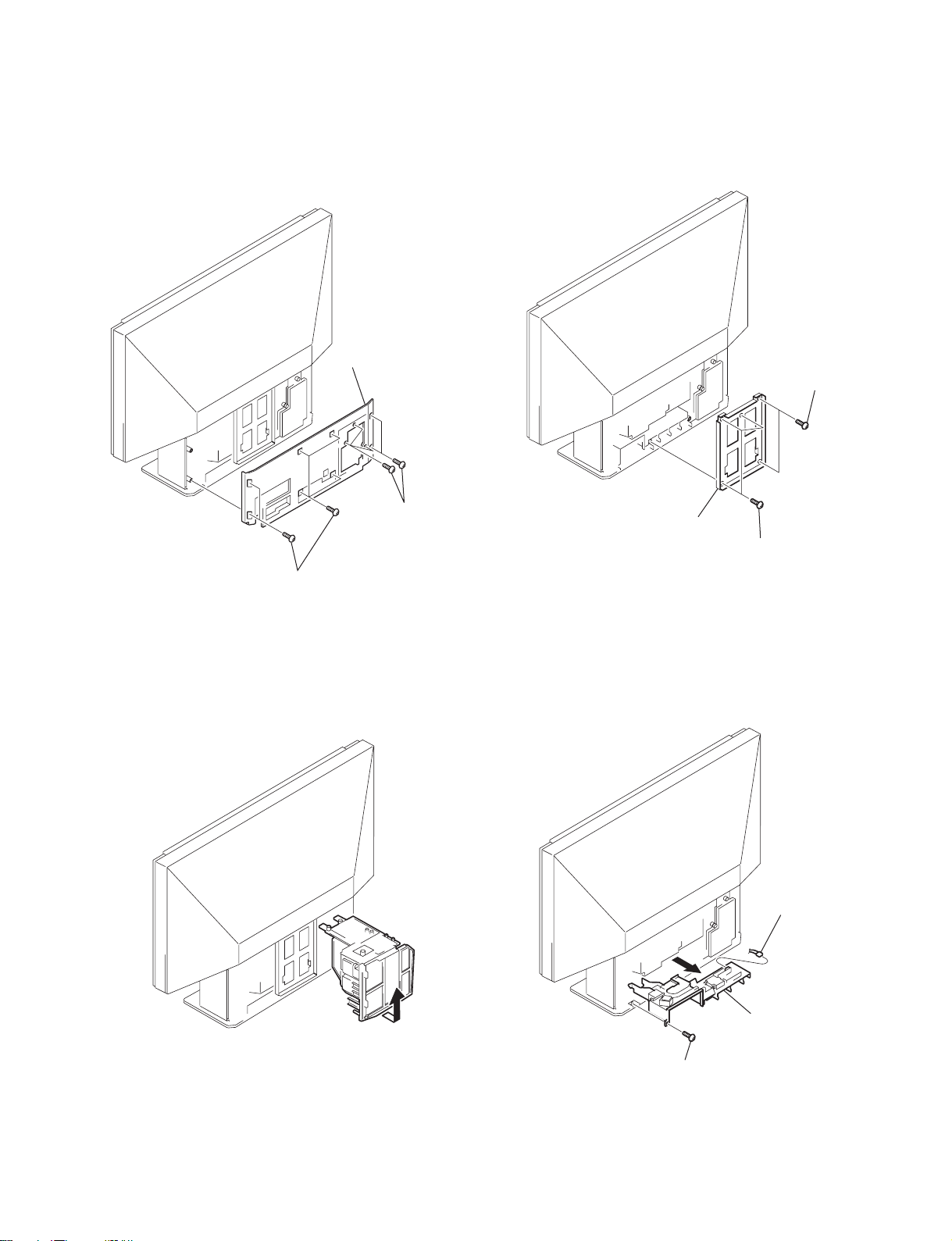
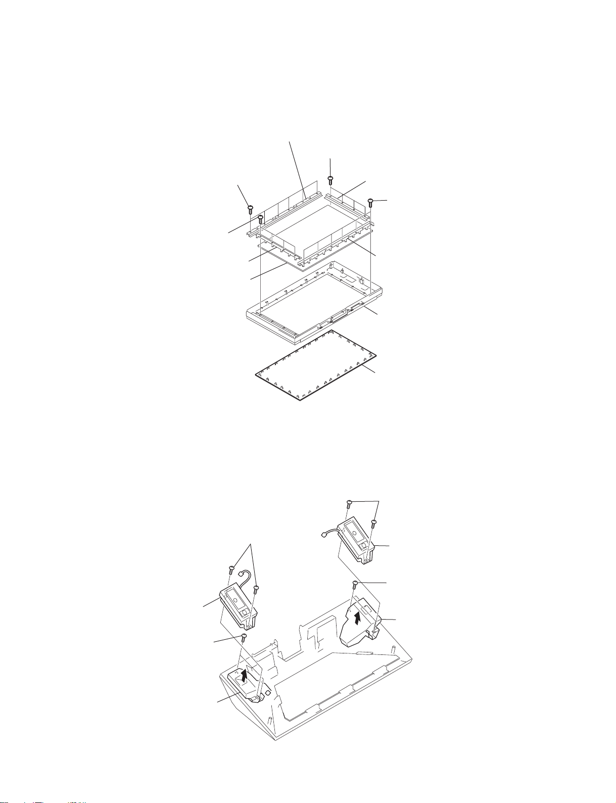
2-1. REAR COVER ASSEMBLY 2-3. OU BRACKET REMOVAL
2
Rear cover assembly
KRM-905
1
Two screws
(+BVTP 4 X 16)
1
1
Six screws
(+BVTP 4 X 16)
Five screws
(+BVTP 4 X 16)
2
OU bracket
1
(+BVTP 4 X 16)
2-2. SERVICE POSITION 2-4. DUCT BLOCK ASSEMBLY
2
Three screws
3
Connector
1
– 8 –
4
1
Screw
(+BVTP 4 X 16)
Duct block assembly
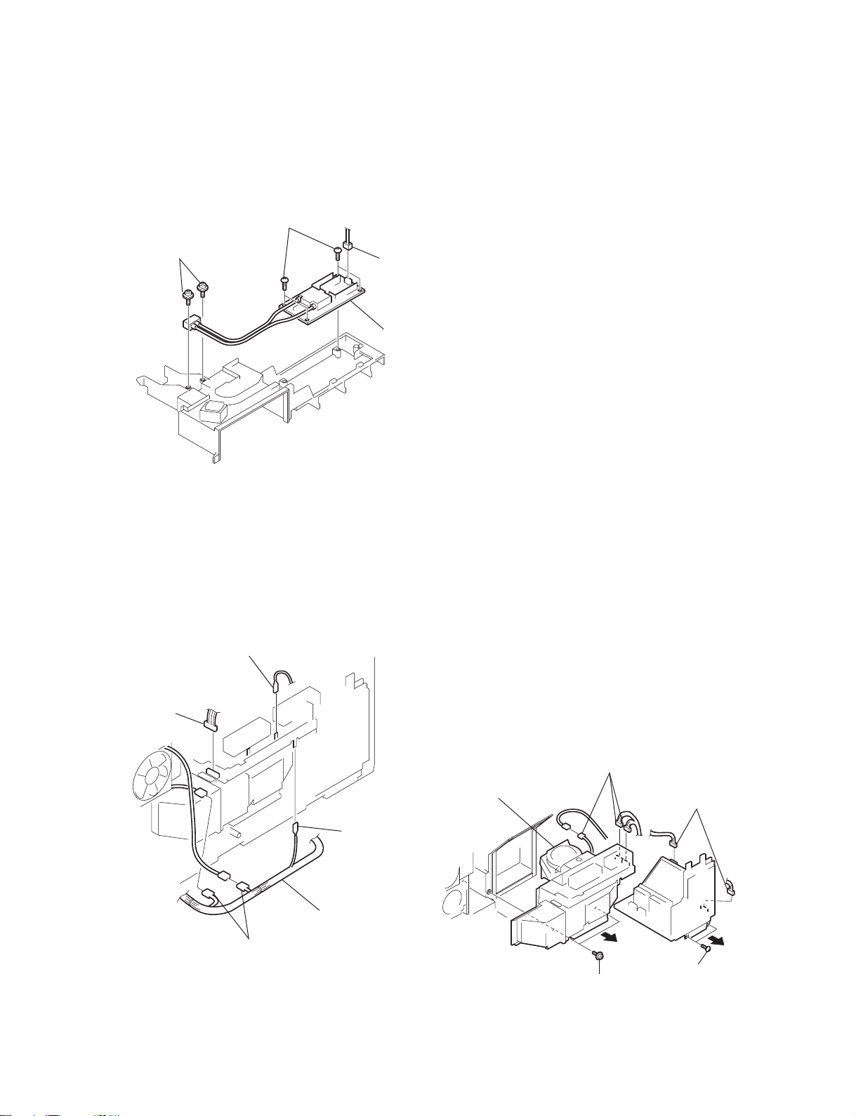
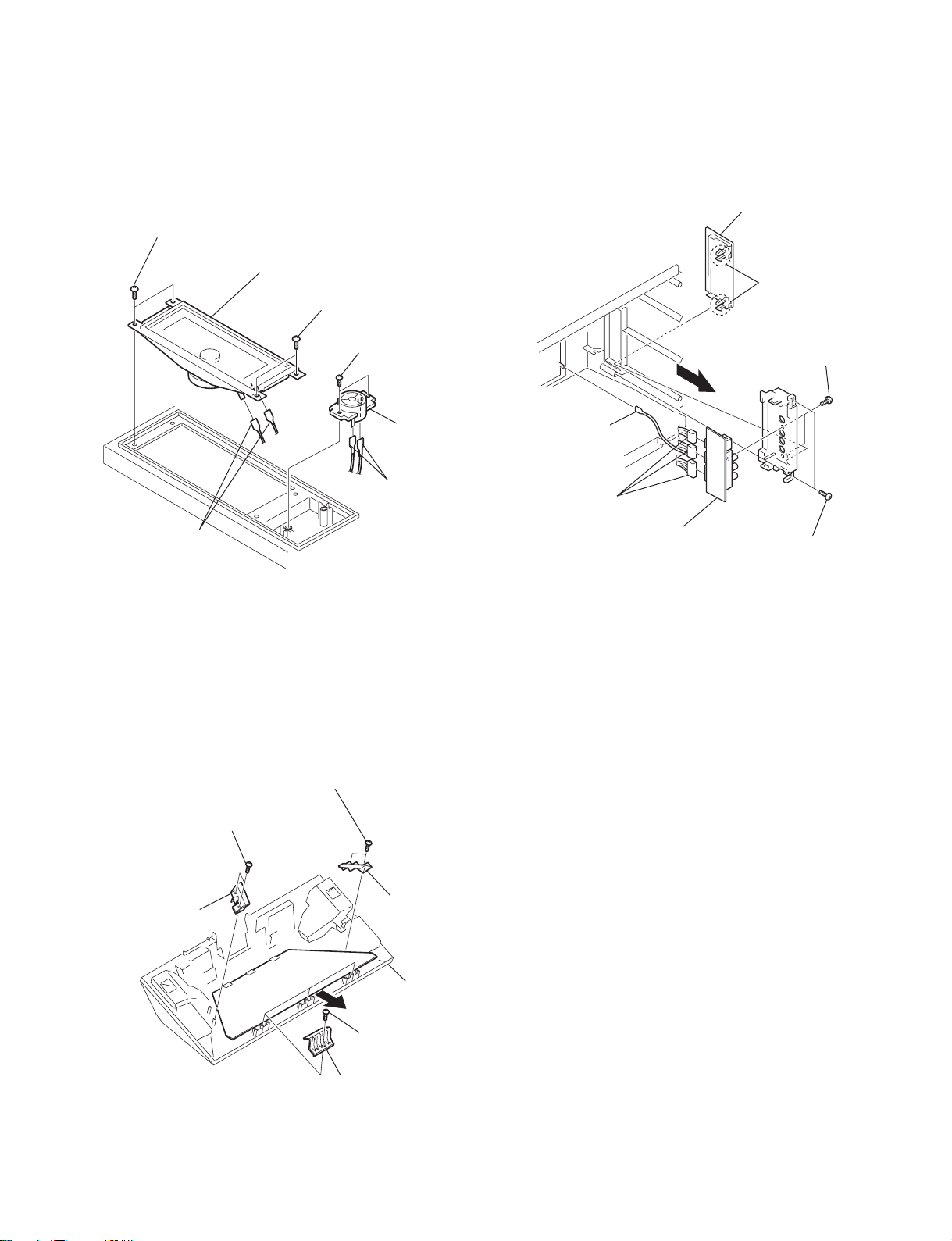
2-5. POWER BLOCK
0 Three connectors
7 T wo connectors
8 T wo screws
(+P 4 X 35)
5 T wo screws
(+BVTP 4 X 16)
9
6
qz Optical unit block assembly
3 Four screws
(+BVTP 3 X 12)
2
Two screws
(+BVWHTP 3 X 12)
KF-50SX200/50SX200K/50SX200U
KRM-905
1 Connector
4 Power block
2-6. OPTICAL UNIT BLOCK ASSEMBLY
2
Connector
1
Fasten tag
3
Conectors
Fasten tag
1
4
Loosen cables
Note: Be careful about the no dust or dirt are on the
surface contacts the optical unit block assembly.
• Clean the periphery of the set.
• Clean the periphery of the optical unit block assembly in
the set (the inside of the control panel, the surface
contacts between the optical unit block assembly and the
bottom cabinet and periphery).
– 9 –
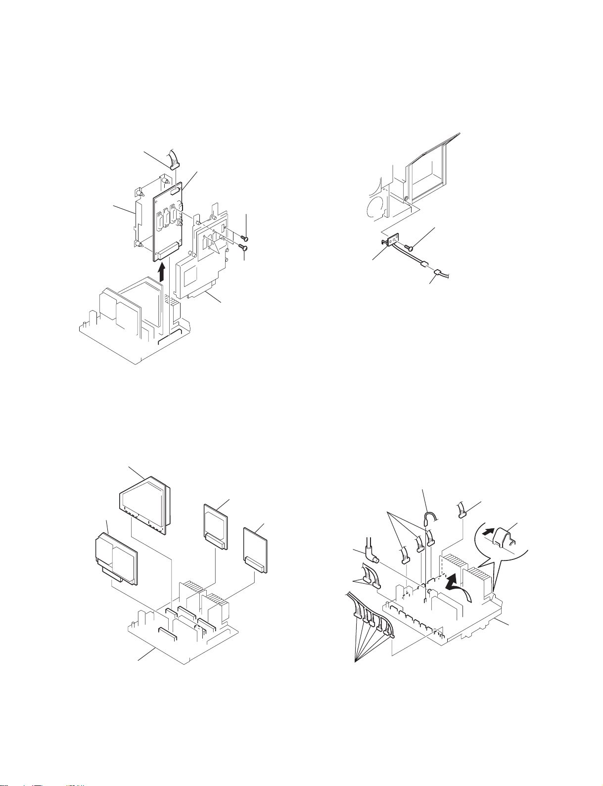
KF-50SX200/50SX200K/50SX200U
2 Connector
5 A board
2 Three connectors
4 Claws
3 RF cable
1 Fasten tag
2 Two
connectors
2 Six connectors
2-7. J BOARD REMOVAL 2-9. T BOARD REMOVAL
1 Connector
7 J board
6 Shield
cover J
2 T w o screws
(+BVTP 3 X 12)
KRM-905
2 Screw
(+BVTP 3 X 12)
5
3 Three screws
(+BVTP 4 X 16)
4 Bracket J
3 T board
1 Connector
2-8. M, BD, S, N BOARDS REMOVAL 2-10. A BOARD REMOVAL
2 BB board
3 S board
1 M board
4 N board
A board
– 10 –
1 T w o screws
(+BVTP 4 X 16)
1 T w o screws
(+BVTP 4 X 16)
2 Control panel
block assembly
4 G block assembly
2 Front cover L
1 Four strikes
1 Four strikes
2 Front cover R
1 Screw
(+BVTP 4 X 16)
2 Fasten tag
1 Screw
(+BVTP 4 X 16)
3 Eight connectors
KF-50SX200/50SX200K/50SX200U
KRM-905
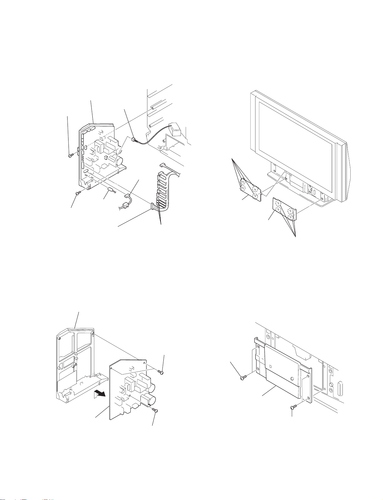
2-13. FRONT COVERS REMOVAL2-11. G BLOCK ASSEMBLY REMOVAL
3 Connector
3 Connector
2 Three fasten tag
2-12. G BOARD REMOVAL 2-14. CONTROL PANEL BLOCK ASSEMBLY
REMOVAL
G bracket
1 T w o screws
(+BVTP 4 X 16)
2
3 G board
1 Screw
(+BVTP 4 X 16)
– 11 –
KF-50SX200/50SX200K/50SX200U
1 Four Screws
(+BVTP 4 X 16)
2 Four screws
(+BVTP 4 X 16)
3 Connector
Screen mirror block assenbly
4
1 Six screws
(+BVTP 4 X 16)
1 Three screws
(+BVTP 4 X 16)
1 Seven screws
(+BVTP 4 X 16)
Mirror cover block assembly
2
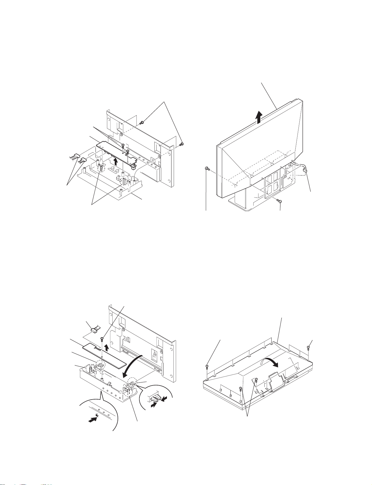
2-15. H4 BOARD REMOVAL 2-17. SCREEN MIRROR BLOCK ASSEMBLY
1 Four screws
(+BVTP 4 X 16)
2 T w o Screws
(+BVTP 3 X 12)
6 H4 board
4
5 T w o connectors
KRM-905
2-16. H2 BOARD REMOVAL 2-18. MIRROR COVER BLOCK ASSEMBLY
8 H2 board
3 Claw
3 Two claws
7 Connector
5 Claw
4 Screw
(+BVTP 3 X 12)
6
2
Indication panel
assembly
REMOVAL
3 Claw
1 Push the control
panel
3
5 Claw
– 12 –
2-19. CONTRAST SCREEN, DIFFUSION PLATES REMOVAL
2 Screen holder (L)
1 Four screws
1 Six screws
(+BVTP 4 X 16)
1 Four screws
(+BVTP 4 X 16)
3 Screen holder (S)
4 Diffusion plates
(+BVTP 4 X 16)
KF-50SX200/50SX200K/50SX200U
KRM-905
3 Screen holder (S)
1 Six screws
(+BVTP 4 X 16)
2 Screen holder (L)
Screen frame assembly
5 Contrast screen
2-20. SQUAWKER BLOCK ASSEMBLIES, WOOFER BLOCK ASSEMBLY REMOVAL
1 T w o screws
(+BVTP 4 X 16)
5 T w o screws
(+BVTP 4 X 16)
6 Squawker
block (R)
assembly
7 T w o screws
(+BVTP 4 X 16)
2 Squawker block (L)
assembly
3 T w o screws
(+BVTP 4 X 16)
4 Woofer block (L)
assembly
8 Woofer block
(R) assembly
– 13 –
1 Two screws (+BVTP 4 X 16)
KF-50SX200/50SX200K/50SX200U
KRM-905
2-23. H1 BOARD REMOVAL2-21. SPEAKERS REMOVAL
2 H1 lid
3 Speaker (13 X 7cm)
2 Fasten tags
2-22. MIRROR REMOVAL
1 T w o screws
(+BVTP 4 X 16)
4 T w o screws
(+BVTP 3 X 12)
6 Speaker
(2cm)
5 Fasten tags
5 Fasten tag
6 Connectors
8 H1 board
4
1 T w o claws
7 T w o screws
(+BVTP 3 X 8)
3 T w o screws
(+BVTP 4 X 16)
1 T w o screws
(+BVTP 4 X 16)
5 T w o screws
(+BVTP 4 X 16)
6 Mirror
holder (R)
2 Mirror
holder (L)
7 Mirror
3 Three screws
(+BVTP 4 X 16)
4 Three mirror holders (U)
– 14 –
SECTION 3
ELECTRICAL ADJUSTMENTS
KF-50SX200/50SX200K/50SX200U
KRM-905
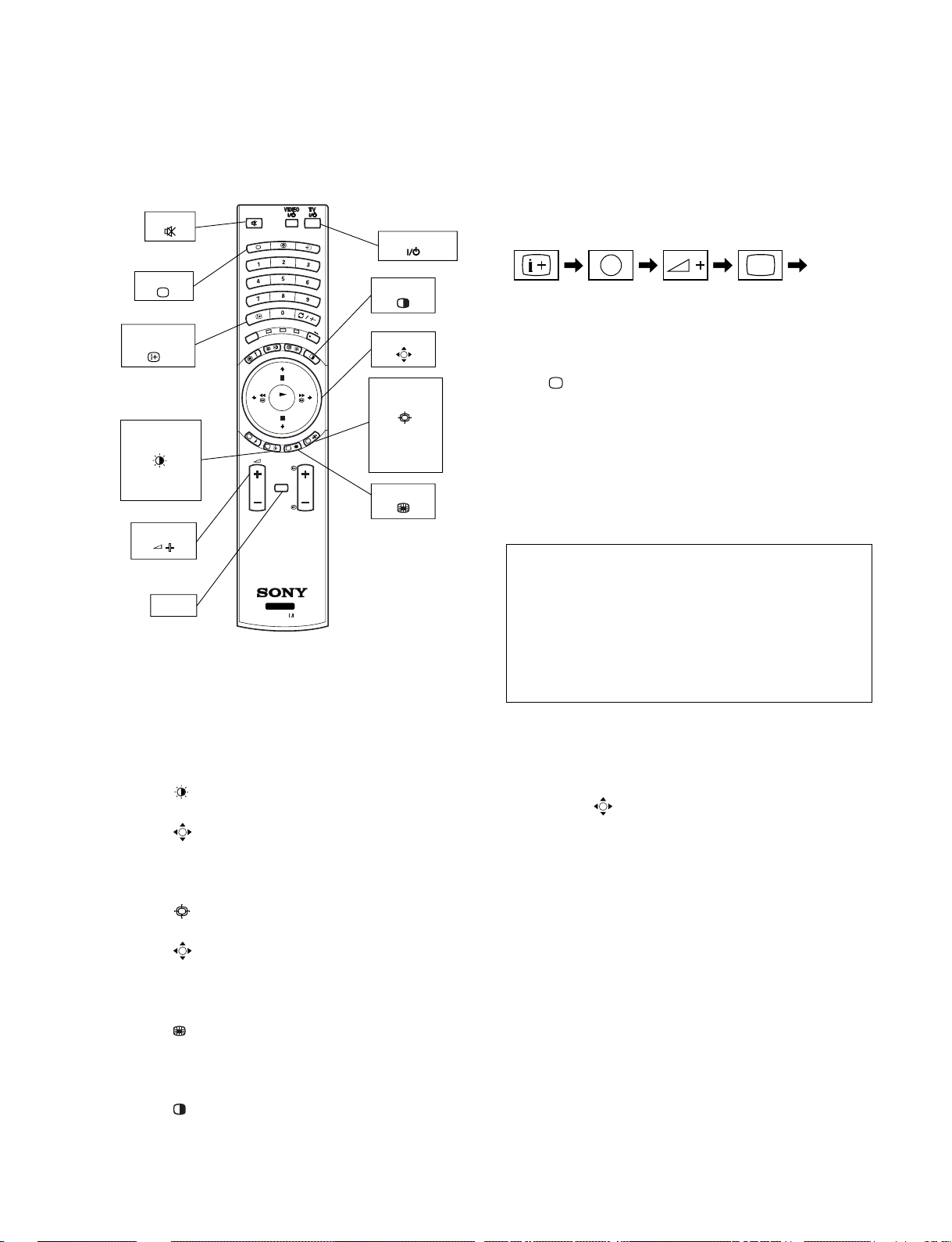
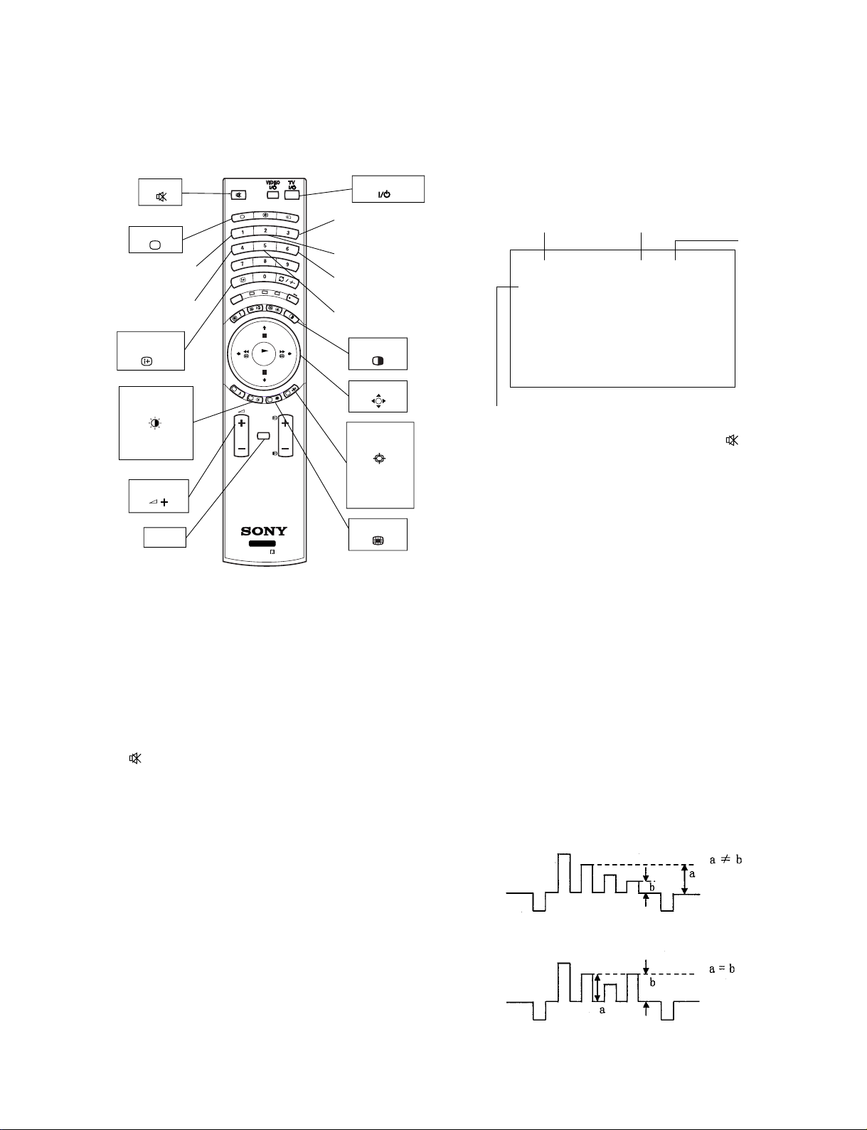
3-1. ADJUSTMENTS WITH COMMANDER
Service adjustment to this model can performed with the supplied
remote commander RM-905.
MUTE
TV STANDBY
TV MODE
ON SCREEN
DISPLAY
PICTURE
MODE
Live/Personal/
Movie/Game
VOLUME +
MENU
TV
DVD
VCR
RM-905
REC
OK
PROG
MENU
TV
ODE
M
PAP
JOYSTICK
SCREEN
MODE
Wide/Zoom/
14:9/4:3/
Smart
PIP
RM-905
3-1-1. How to Select Each Mode
1. Selection of Mode between PAL and NTSC
PAL mode : Enter PAL signal with color burst.
NTSC mode: Enter NTSC signal with color burst. (VIDEO
input only)
2. Selection of Picture Mode
1) Press “
2) Press v or V key on the joystick to select picture mode and
press “ (OK)” button. At this time, normal screen comes
back. (In the TT mode, the menu is switched to the Service
menu.)
3. Selection of Screen Mode
1) Press “ (BLUE)” button on the commander.
2) Press v or V key on the joystick to select screen mode and
press “
back. (In the TT mode, the menu is switched to the Service
menu.)
4. Displaying Multi PIP Mode
1) Press “
2) Press it once more, normal screen comes back. (In the TT
mode, the menu is switched to the Service menu.)
5. Displaying PAP Mode
1) Press “ ” button on the commander.
2) Press it once more, normal screen comes back. (In the TT
mode, the menu is switched to the Service menu.)
(GREEN)” button on the commander.
(OK)” button. At this time, normal screen comes
(YELLOW)” button on the commander.
3-1-2. How to Enter TT Mode
1. Turn on the main power switch to place this set in standby
mode. (LED will light in red.)
2. Press the buttons on commander as follows, and the TT
mode will be selected.
Enter the
“TT MODE”
(
DISPLAY
5
(DIGIT 5) (VOLUME +) (TV MODE)ON SCREEN
)
“TT - -” will appear in the top right corner of the screen.
Other status information will also be displayed.
3. If “
(TV MODE)” button or “-” + “-” button is pressed,
the set exits from the TT mode and returns to normal TV mode.
3-1-3. How to Enter Service Menu
1. Select TT mode.
2. Press “MENU” button on the commander once, and normal
menu screen will appear, or press it once more, and the following service menu screen will appear.
Service AE5(A)
Initialising
Reset Devices
Monitoring
Device Register Setting
Special Adjustment
Select : v V Next menu : B
3. Following the screen, press v or V key on the joystick to
select the desired item, and press B key to enter the selected
item.
4. Press v or V key on the joystick to change data of each item,
and press “
(OK)” button to write changed data.
(Except Projector Engine mode)
5. To return from each item, press b key on the joystick. Or, to
return to the TT mode, press the “MENU” button.
(Except Projector Engine mode)
– 15 –

KF-50SX200/50SX200K/50SX200U
KRM-905
3-1-4. Screen Display for Service Menu
If each item of service menu is selected, the following screen is
displayed.
• Initialising
Initialising
Model Setting
Destination Setting
Basic Setting
Feature Setting
Select : v V Next menu : B
• Initialising b Model Setting
Model Setting
1 KV-29FX60
2 KV-29FC60
3 KV-29FS60
4 KV-28FX60
5 KV-32FX60
6 KV-32FS60
7 KV-28FC60
8 KV-32FC60
9 KP-44PS3
10 KP-51PS3
11 KF-50SX200
12 KDP-44NX1U
13 KDP-51NX1U
14 KP-48PS1/PS2
15 KP-53PS1/PS2
16 KP-61PS1/PS2
17 KP-44PS2
18 KP-51PS2
19 KF-50SX100
BLACK = No conformity
GREEN = Compatible Model
RED = Conformity for all data
Select : v V Last menu : b Set Model : B
• Initialising b Destination Setting
Destination Setting
Multi
A
B
D
E
K
R
U
GA
BLACK = No conformity
GREEN = Compatible Destination
RED = Conformity for all data
• Initialising b Basic Setting
Basic Setting
No Descr. Min Max Data
1 Sys. B/G OFF ON ON
2 Sys. D/K OFF ON ON
3 Sys. L OFF ON ON
4 Sys. I (UK) OFF ON ON
5 Sys. I (IRL) OFF ON OFF
6 TXT Nat.Option 1 4 3
7 Simple PAT OFF ON ON
8 16 : 9 CRT OFF ON ON
9 Sub-Woofer OFF ON ON
10 Auto Stand-By OFF ON ON
11 Comb-Filter OFF ON ON
12 Auto YC det OFF ON ON
13 Auto Comb det OFF ON ON
14 AV2 Available OFF ON ON
15 AV3 Available OFF ON ON
16 AV4 Available OFF ON ON
17 AV3 Front&Rear OFF ON OFF
18 SECAM Tape OFF ON ON
19 AV1 SoundMute OFF ON OFF
Select : v V Last menu : b Enter Item : B
• Initialising b Feature Setting
Feature Setting
No Descr. Min Max Data
1 PAP OFF ON ON
2 PAT OFF ON ON
3 INDEX OFF ON ON
4 EPG OFF ON ON
5 Full EPG OFF ON ON
6 PictBoostBypass OFF ON OFF
Select : v V Last menu : b Enter Item : B
• Reset Devices
Reset Devices
Colour Decoder 1
Colour Decoder 2
Audio/Video Switch
MID-X
External PLL MID-X
Gate Array Chip
AutoWide
Sound
Picture Booster
MCP
Analog NR
Select : v V Last menu : b Reset Dev. : B
Select : v V Last menu : b Set Dest. : B
– 16 –

KF-50SX200/50SX200K/50SX200U
KRM-905
• Monitoring
Monitoring
Device Status Monitor
Error Monitor
LCD-Engine error menu
Production Monitor
NVM Monitor
Format Monitor
CNI Monitor
Select : v V Next menu : B
• Device Register Setting
Device Register Setting
Colour Decoder 1
Colour Decoder 2
Audio/Video Switch
MID-X
External PLL MID-X
Gate Array Chip
Autowide
Sound
Projector Engine
Picture Booster
MCP
Analog NR
• Device Register Setting b Colour Decoder 2
Colour Decoder 2
No Descr. Def. Min Max Data
1 TINT 31 0 63 31
2 SUB COLOUR 7 0 15 7
3 SUB CONTR 7 0 15 7
4 SHARP GAIN 8 0 15 8
5 Y-OUT LEV. 35 0 63 35
6 C-OUT LEV. 45 0 63 45
7 Y-DL 8 0 10 8
8 Cr OFF. 1 7 0 15 7
9 Cb OFF. 1 7 0 15 7
10 Cr OFF. 2 7 0 15 7
11 Cb OFF. 2 7 0 15 7
12 V CD FREQ 3 0 7 3
13 V CD MODE 1 0 3 1
14 MVM OFF OFF ON OFF
15 S R-Y ADJ 7 0 15 7
16 S B-Y ADJ 2 0 15 2
17 BELL/HPF 2 0 3 2
18 BELL F0 OFF OFF ON OFF
19 S GP 0 0 3 0
Select : v V Last menu : b Enter Item : B
• Device Register Setting b Audio/Video Switch
Audio/Video Switch
Select : v V Next menu : B
• Device Register Setting b Colour Decoder 1
Colour Decoder 1
No Descr. Def. Min Max Data
1 TINT 31 0 63 31
2 SUB COLOUR 7 0 15 7
3 SUB CONTR 7 0 15 7
4 SHARP GAIN 8 0 15 8
5 Y-OUT LEV. 35 0 63 35
6 C-OUT LEV. 45 0 63 45
7 Y-DL 8 0 10 8
8 Cr OFF.1 7 0 15 7
9 Cb OFF.1 7 0 15 7
10 Cr OFF.2 7 0 15 7
11 Cb OFF.2 7 0 15 7
12 V CD FREQ 3 0 7 3
13 V CD MODE 1 0 3 1
14 MVM OFF OFF ON OFF
15 S R-Y ADJ 7 0 15 7
16 S B-Y ADJ 2 0 15 2
17 BELL/HPF 2 0 3 2
18 BELL F0 OFF OFF ON OFF
19 S GP 0 0 3 0
Select : v V Last menu : b Enter Item : B
No Descr. Def. Min Max Data
• Device Register Setting b MID-X
MID-X
No Descr. Def. Min Max Data
1 M H POS 8 –31 31 8
2 S H POS 2 –8 8 2
3 D YS SEL 1 0 3 1
4 D YS DELAY 7 0 7 7
5 D SYNC MOD ON OFF ON ON
6 Text Sharp OFF OFF ON OFF
Select : v V Last menu : b Enter Item : B
– 17 –

KF-50SX200/50SX200K/50SX200U
KRM-905
• Device Register Setting b External PLL MID-X
External PLL MID-X
No Descr. Def. Min Max Data
1 VCO7-0PAL 184 0 255 184
2 VCO7-0NTSC 172 0 255 172
3 VCO11-8 6 0 15 6
4 DIV1,2,4,8 2 0 3 2
5 Fine Delay 0 0 63 0
6 Coar.Delay 0 0 3 0
7 Ch. Pump 0 0 3 0
8 PD Pol. ON OFF ON ON
9 DSync Wdth 3 0 3 3
10 Dsync Del OFF OFF ON OFF
11 Sync Pol ON OFF ON ON
12 DSync Pol ON OFF ON ON
13 Clk En ON OFF ON ON
14 NClk En OFF OFF ON OFF
15 Clk/2 En OFF OFF ON OFF
16 NClk/2 En OFF OFF ON OFF
17 DSync En ON OFF ON ON
18 Unlock En OFF OFF ON OFF
19 VCO Bypass ON OFF ON ON
20 Synth Pwr ON OFF ON ON
21 Rdout Pwr OFF OFF ON OFF
22 DIVOUT En ON OFF ON ON
23 DSync Byp OFF OFF ON OFF
24 DSync Hold OFF OFF ON OFF
Select : v V Last menu : b Enter Item : B
• Device Register Setting b Gate Array Chip
Gate Array Chip
No Descr. Def. Min Max Data
1 SMART OFF OFF ON OFF
2 ROM Curve 0 0 1 0
3 H Offset 0 -15 15 0
• Device Register Setting b Sound
Sound
No Descr. Def. Min Max Data
1 Carr.-Mute ON OFF ON ON
2 SCART1 Vol 79 0 127 79
3 SCART2 Vol 79 0 127 79
4 SCART-Pr. 27 0 127 27
5 I2S1-Pr. 16 0 127 16
6 I2S2-Pr. 16 0 127 16
7 FM Pr. 27 0 127 27
8 BG Nic.Pr. 53 0 127 53
9 L Nic. Pr. 59 0 127 59
10 DK Nic.Pr. 53 0 127 53
11 I Nic. Pr. 97 0 127 97
12 Irl NicPr. 97 0 127 97
13 Subw. Vol. -2 -127 0 -2
14 Bass Offs 0 -3 3 0
15 TrebleOffs 0 -3 3 0
16 Loudn.Offs 0 0 9 0
17 HP-VolOffs -2 -5 5 -2
18 M-S Limit 30 -128 127 30
19 M-B Limit -30 -128 127 -30
20 S-M Limit 12 -128 127 12
21 S-B Limit -20 -128 127 -20
22 B-M Limit -12 -128 127 -12
23 B-S Limit 20 -128 127 20
24 Err. Max 40 0 255 40
25 Err. Min 18 0 255 18
26 Vol.Offset 0 -6 0 0
27 High Dev. OFF OFF ON OFF
28 FIR2 500k ON OFF ON ON
29 Loud.Gain 0 0 68 29
30 Loud.Mode 50 0 8 8
31 Virt.Surr. OFF OFF ON OFF
32 Spat.Eff. 64 0 127 0
33 Virt.Eff. 90 0 127 90
34 Virt.Mode 6 5 6 6
35 Noise Gen. OFF OFF ON OFF
36 Channel 10 10 13 10
Select : v V Last menu : b Enter Item : B
Select : v V Last menu : b Enter Item : B
• Device Register Setting b Auto wide
Auto wide
No Descr. Def. Min Max Data
1 Upara ON OFF ON ON
2 Upthin OFF OFF ON OFF
3 Enjtoz OFF OFF ON OFF
4 X149j ON OFF ON ON
5 Syncslc OFF OFF ON OFF
6Tm 1 0 3 1
7 Uprlvl OFF OFF ON OFF
8 Ofslvl OFF OFF ON OFF
9 Alpf 3 0 3 3
10 eddec2 3 0 3 3
11 Lnstblz ON OFF ON ON
12 Lnhys OFF OFF ON OFF
13 Drkpri ON OFF ON ON
Select : v V Last menu : b Enter Item : B
• Device Register Setting b Picture Booster
Picture Booster
No Descr. Def. Min Max Data
1 DEM OFF OFF ON OFF
Select : v V Last menu : b Enter Item : B
– 18 –

KF-50SX200/50SX200K/50SX200U
KRM-905
• Device Register Setting b MCP
MCP
No Descr. Def. Min Max Data
1 Contrast 46 0 63 46
2 Hue 32 0 63 32
3 System 1 0 3 1
4 Colour 29 0 63 24
5 Brightness 55 0 63 55
6 Sharpness 31 0 63 29
7 R-Drive 42 0 63 42
8 D-Col OFF OFF ON OFF
9 G-Drive 42 0 63 42
10 B-Drive 42 0 63 42
11 R-Cutoff 20 0 63 20
12 G-Cutoff 20 0 63 20
13 B-Cutoff 20 0 63 20
14 H-Width 0 0 3 0
15 CR-Offset 1 2 0 15 11
16 CB-Offset 1 2 0 15 11
17 Sub-Contr. 7 0 15 7
18 Sub-Colour 7 0 15 7
19 Sub-Hue 7 0 15 7
20 CTI-Level 1 0 3 1
21 R-Y/R 10 0 15 10
22 R-Y/B 15 0 15 15
23 G-Y/R 10 0 15 10
24 G-Y/B 7 0 15 7
25 Gamma 3 0 15 3
26 P-Abl 15 0 15 15
27 BLK-Bottom 5 0 15 5
28 Sub-Sharp 1 0 3 1
29 Sharp.F0 2 0 3 2
30 Pre/Over 1 0 3 1
31 LTI-Level 1 0 3 1
32 DC-Tran 0 0 3 0
33 DPIC-Level 0 0 3 0
• Special Adjustment
Special Adjustment
No Descr. Min Max Data
1 RGB Level 0 7 0
2 RGB Gain 0 31 23
3 RGB PAT Level 0 7 0
4 RGB PAT Gain 0 31 18
5 Extra FW 0 255 255
6 EPG ChkS Check OFF ON ON
7 Slicer High OFF ON ON
8 FCW Wide OFF ON ON
9 Mpeg NR OFF ON OFF
10 Notch Filter OFF ON OFF
11 NLD step -7 0 -1
12 PKD step -15 0 -5
13 CRD step 0 15 3
14 SHP step -7 0 -3
15 COL step -7 0 -1
16 NTSC AutoYc AV2 OFF ON OFF
17 NTSC AutoYc AV3 OFF ON OFF
18 RGB Disable OFF ON OFF
19 Telop C/M OFF ON ON
20 Intern GD OFF ON ON
21 AV2 YC mix out OFF ON OFF
22 Line 318 TXT OFF ON ON
23 L Gating Main OFF ON OFF
24 L Gating Sub OFF ON OFF
25 Audio Gain Sub OFF ON OFF
26 Auto Mute Sub OFF ON ON
Select : v V Last menu : b Enter Item : B
Select : v V Last menu : b Enter Item : B
• Device Register Setting b Analog NR
Analog NR
No Descr. Def. Min Max Data
– 19 –
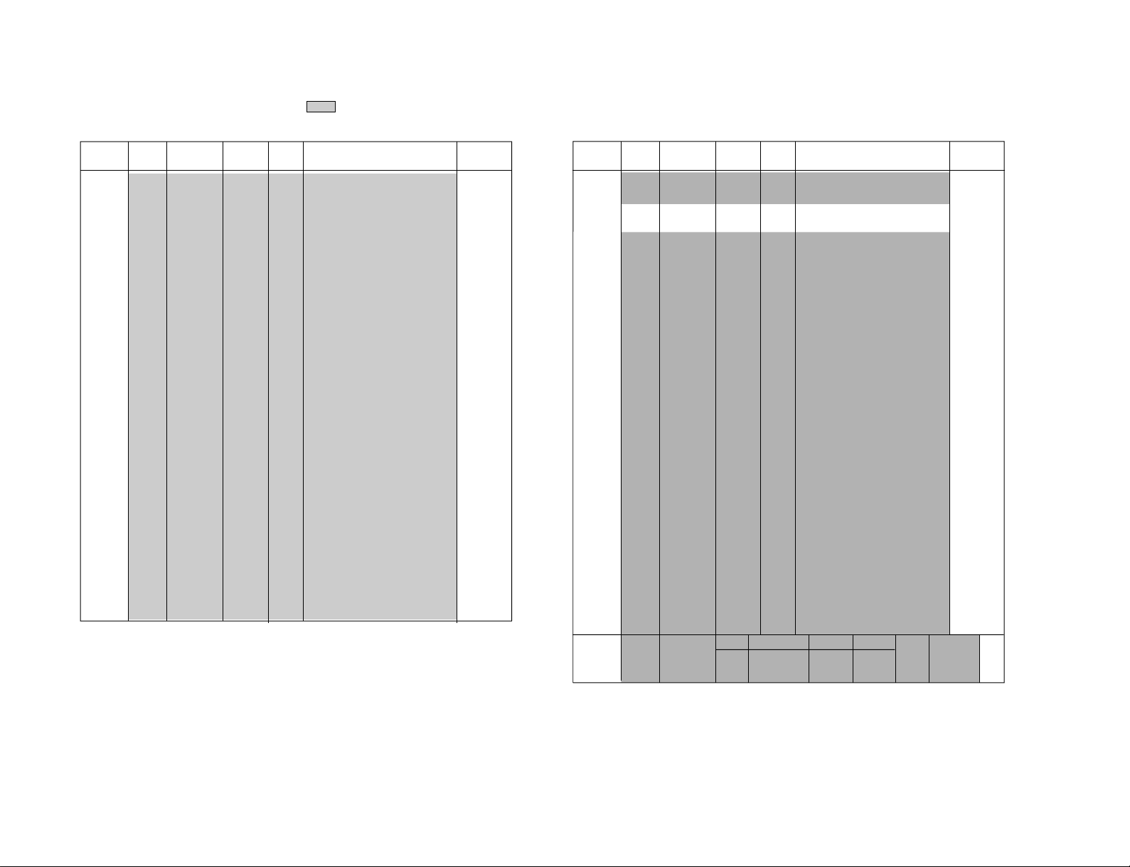
3-1-5. Service List (Projector Engine)
: Fixed data
D9512 TG
Category
D9512 TG 0 INV CTL 0 0, 1 INVERT CONTROL CXD9512
– 20 –
Item Adjustment Standard Data
number item data range
1 POS CTL 13 0-15 POSITION CONTROL
2 H POS 9 0-255 TG H POSITION
3 V POS H 4 0-255 TG V POSTION H
4 V POS D 30 0-255 TG V POSITION DOT
5 HST POL 0 0, 1 HST POLARITY
6 HCK W 0 0, 1 HCK WIDTH
7 HST POS 15 0-63 HST POSITION
8 HCK POL 1 0, 1 HCK POLARITY
9 HCK A-INV 0 0, 1 HCK AUT O INVERT
10 VST POL 0 0, 1 VST POLARITY
11 VST A-INV 0 0, 1 VST AUTO INVERT
12 HST PHA 1 0-15 HST PHASE
13 VCK POL 0 0, 1 VCK POLARITY
14 VST POS 0 0-127 VST POSITION
15 ENB POS 23 0-255 ENB POSITION
16 ENB W 40 0-255 EMB POSITION
17 BLK ON 0 0, 1 BLK ON
18 BLK POL 0 0, 1 BLK POLARITY
19 PCG POS 2 0-63 PCG POSITION
20 PCG B-OR 0 0, 1 PCG BLK OR
21 PCG B-SEL 0 0, 1 PCG BLK SELECT
22 PCG W 3 0-63 PCG WIDTH
23 PRG POS 2 0-63 PRG POSION
24 PRG B-OR 0 0, 1 PRG BLK OR
25 PRG B-SEL 0 0, 1 PRG BLK SELECT
26 PRG W 9 0-63 PRG WIDTH
27 BLK POS 0 0-255 BLK POSTION
28 BLK W 0 0-255 BLK WIDTH
29 CLR W 0 0-255 CLR WIDTH
Note Device
D9512 IM
Category
D9512 IM 0 V-ST-POS 9 0-255 V START POSITION CXD9512
Item Adjustment Standard Data
number item data range
1 H-ST-POS 97 0-255 H START POSITION
2 SUB CON 32 0-63 SUB CONTRAST LEVEL
3 SUB BRT 12 0-63 SUB BRIGHT LEVEL
4 V BLKT H 0 0-255 V BLANKING POSITION TOP
5 V BLKT L 0 0.-3 V BLANKING POSITION TOP2
6 V BLKB H 0 0-255
7 V BLKB L 0 0-3
8 H BLKL H 0 0-255 H BLANKING POSITION LEFT
9 H BLKL L 0 0-3 H BLANKING POSITION LEFT 2
10 H BLKR H 0 0-255 H BLANKING POSITION RIGHT
11 H BLKR L 0 0-3
12 ASL SW 0 0, 1 ASL SWITCH
13 ASL SEL 0 0-3 ASL SELECT
14 B PIC LV 0 0-15 BLUE PICASL LEVEL
15 B BRT LV 15 0-15 BLUE BRTASL LEVEL
16 G PIC LV 0 0-15 GREEN PICASL LEVEL
17 G BRT LV 15 0-15 GREEN BRTASL LEVEL
18 R PIC LV 0 0-15 RED PICASL LEVEL
19 R BRT LV 15 0-15 RED BRTASL LEVEL
20 PIC AREA 7 0-7 PICASL AREA
21 BRT AREA 7 0-7 BRTASL AREA
22 PIC ST 0 0-3 PICASL START TIMING
23 BRT ST 0 0-3 BRTASL START TIMING
24 PRE SL 3 0-3 PRE SLOPE
25 POST SL 3 0-3 POST SLOPE
26 APC MODE 2 0-2 APC MODE
27 APC SW 1 0, 1 APC SWITCH
28 APC TH 10 0-255 APC THRESHOLD
29 APC LIMT 30 0-63 APC LIMITTER
30 APC LEV 60 0-255 APC LEVEL
LIVE PERSONAL MOVIE GAME
31 G-PICT 100 69 66 69 0-100 PICTURE
32 G-BRIGHT 51 51 51 51 0-100 BRIGHT
V BLANKING POSITION BOTTOM
V BLANKING POSITION BOTTOM 2
H BLANKING POSITION RIGHT 2
Note Device
KF-50SX200/50SX200K/50SX200U
KRM-905
D9512 WB
Category
D9512 WB
– 21 –
Item Adjustment Standard Data
number item data range
0 B GAIN 127 0-255 W/B GAIN BLUE CXD9512
1 G GAIN 127 0-255 W/B GAIN GREEN
2 R GAIN 127 0-255 W/B GAIN RED
3 B BIAS 85 0-255 W/B BIAS BLUE
4 G BIAS 85 0-255 W/B BIAS GREEN
5 R BIAS 85 0-255 W/B BIAS RED
6 B GAIN H 143 0-255 W/B GAIN BLUE
7 G GAIN H 125 0-255 W/B GAIN GREEN
8 R GAIN H 130 0-255 W/B GAIN RED
9 B BIAS H 127 0-255 W/B BIAS BLUE
10 G BIAS H 130 0-255 W/B BIAS GREEN
11 R BIAS H 128 0-255 W/B BIAS RED
12 B GAIN L 115 0-255 W/B GAIN BLUE
13 G GAIN L 125 0-255 W/B GAIN GREEN
14 R GAIN L 144 0-255 W/B GAIN RED
15 B BIAS L 128 0-255 W/B BIAS BLUE
16 G BIAS L 127 0-255 W/B BIAS GREEN
17 R BIAS L 120 0-255 W/B BIAS RED
Note Device
D9512 TES
Category
D9512 TES
Item Adjustment Standard Data
number item data range
0 REF PER 1 0, 1 REFRESH PERMISSION CXD9512
1 REF LENG 0 0-7 REFRESH LENGTH
2 G-LUT SW 0 0, 1 GAMMA LUT THROUGH
3 CORR WGT 2 0-3 CORRECT WEIGHT
4 SHAD SW 0 0, 1 SHADING SWITCH
5 3D-G SW 1 0, 1 3D GAMMA SWITCH
6 3D-G Z 0 0, 1 3D GAMMA MODE Z
7 3D-G VH 0 0, 1 3D GAMMA MODE VH
8 3D-G BS 1 0, 1 3D GAMMA BLOCK SIZE
9 AGC P SW 1 0, 1 AGC PULSE SWITCH
10
11
12
AGC SHP POS
AGC SHP SEL
AGC SHP W
43 0-127 AGC SH PULSE POSITION
1 0-3 AGC SH PULSE SELECT
2 0-63 AGC SH PULSE WIDTH
Note Device
D9512 TPN
Category
D9512 TPN
number item data range
D9512 TFR
Category
D9512 TFR
number item data range
Item Adjustment Standard Data
0
T-PATN SW
1 T-SIG SEL 1 0-7 TEST SIGNAL SELECT
2 PATN DIR 1 0, 1 PATTERN DIRECTION
3 SIG LV DIR 0 0, 1 SIGNAL LEVEL DIRECTION
4
T-PATN PIT
5 B-LV 25 0-63 BLUE TEST PATTERN LEVEL
6 G-LV 25 0-63 GREEN TEST PATTERN LEVEL
7 R-LV 25 0-63 RED TEST PATTERN LEVEL
8
T-PATN RGB
Item Adjustment Standard Data
0 CRIP 1 0, 1 FRAME CRIP CXD9512
1 CUR TOP 0 0, 1 FRAME CURSOR TOP
2 CUR BOT 0 0, 1 FRAME CURSOR BOTTOM
3 CUR L 0 0, 1 FRAME CURSOR LEFT
4 CUR R 0 0, 1 FRAME CURSOR RIGHT
5 POS TOP 0 0-255 FRAME POSITION TOP
6 POS BOT 255 0-255 FRAME POSITION BOTTOM
7 POS L 0 0-255 FRAME POSION LEFT
8 POS R 255 0-255 FRAME POSITION RIGHT
9 OSD B 25 0-31 BLUE OSD LEVEL
10 OSD G 25 0-31 GREEN OSD LEVEL
11 OSD R 25 0-31 RED OSD LEVEL
12 OSD YM 0 0-7 PICTURE HALF TONE LEVEL
13 OSD I 3 0-7 OSD HALF TONE LEVEL
0 0, 1 TEST PATTERN SWITCH CXD9512
144 0-255 TEST PATTERN PITCH
4 0-7 RGB TEST ENABLE
Note Device
Note Device
KF-50SX200/50SX200K/50SX200U
KRM-905
GAMMA
Category
GAMMA 0 ADJ ON 0 0, 1 INVERT CONTROL
– 22 –
Item Adjustment Standard Data
number item data range
1 GAMMA R0 255 0-255 GAMME ADJ (R)
2 GAMMA R1 255 0-255 GAMME ADJ (R)
3 GAMMA R2 255 0-255 GAMME ADJ (R)
4 GAMMA R3 255 0-255 GAMME ADJ (R)
5 GAMMA R4 255 0-255 GAMME ADJ (R)
6 GAMMA R5 255 0-255 GAMME ADJ (R)
7 GAMMA R6 255 0-255 GAMME ADJ (R)
8 GAMMA R7 255 0-255 GAMME ADJ (R)
9 GAMMA G0 255 0-255 GAMME ADJ (G)
10 GAMMA G1 255 0-255 GAMME ADJ (G)
11 GAMMA G2 255 0-255 GAMME ADJ (G)
12 GAMMA G3 255 0-255 GAMME ADJ (G)
13 GAMMA G4 255 0-255 GAMME ADJ (G)
14 GAMMA G5 255 0-255 GAMME ADJ (G)
15 GAMMA G6 255 0-255 GAMME ADJ (G)
16 GAMMA G7 255 0-255 GAMME ADJ (G)
17 GAMMA B0 255 0-255 GAMME ADJ (B)
18 GAMMA B1 255 0-255 GAMME ADJ (B)
19 GAMMA B2 255 0-255 GAMME ADJ (B)
20 GAMMA B3 255 0-255 GAMME ADJ (B)
21 GAMMA B4 255 0-255 GAMME ADJ (B)
22 GAMMA B5 255 0-255 GAMME ADJ (B)
23 GAMMA B6 255 0-255 GAMME ADJ (B)
24 GAMMA B7 255 0-255 GAMME ADJ (B)
LCD-DR
Category
LCD-DR 0 FRP CNT 0 0, 1 FR PULSE CONT
Item Adjustment Standard Data
number item data range
1 R VCOM 127 0-255 V COM ADJ (R)
2 R ODD VR 24 0-255 ODD ADJ (R)
3 R EVEN VR 24 0-255 EVEN ADJ (R)
4
R DLY CNT
R DA VSET
5
6 G VCOM 127 0-255 V COM ADJ (G)
7 G ODD VR 194 0-255 ODD ADJ (G)
8
G EVEN VR
G DLY CNT
9
10
G DA VSET
11 B VCOM 127 0-255 V COM ADJ (B)
12 B ODD VR 245 0-255 ODD ADJ (B)
B EVEN VR
13
14
B DLY CNT
B DA VSET
15
16
R VREF SEL
G VREF SEL
17
18
B VREF SEL
127 0-255 DLY CONT (R)
44 0-255 D/A VOLTAGE SET (R)
24 0-255 EVEN ADJ (G)
127 0-255 DLY CONT (G)
109 0-255 D/A VOLTAGE SET (G)
97 0-255 EVEN ADJ (B)
127 0-255 DLY CONT (B)
11 0-255 D/A VOLTAGE SET (B)
0 0, 1 VOLTAGE REF SELECT (R)
0 0, 1 VOLTAGE REF SELECT (G)
0 0, 1 VOLTAGE REF SELECT (B)
Note Device
Note Device
GPLL-C-JPN
Category
GPLL-C-JPN
Item Adjustment Standard Data
number item data range
0 VCOL 248 0-255 COUNTER L
1 VCOH 5 0-15 COUNTER H
2 DIV 2 0-3 DIVIDER
3 CODL 0 0-3 DELAY
4 FIDL 15 0-31 FINE DELAY
5 PPOL 1 0, 1
6 CPMP 2 0-3 CHARGE PUMP
7 UNLO 1 0, 1 UNLOCK OUT ON/OFF
8 DSYN 1 0, 1 DELAY SYNC ON/OFF
9 CL2 1 0, 1 1/2 TTL CLOCK ON/OFF
10 DSYP 0 0, 1
11 SYP 0 0, 1 INPUT SYNC POLARITY
PLL-C-N/P
Category
PLL-C-N/P
Item Adjustment Standard Data
number item data range
0 VCOL 248 0-255 COUNTER L
1 VCOH 5 0-15 COUNTER H
2 DIV 2 0-3 DIVIDER
3 CODL 0 0-3 DELAY
4 FIDL 15 0-31 FINE DELAY
5 PPOL 1 0, 1
6 CPMP 2 0-3 CHARGE PUMP
7 UNLO 1 0, 1 UNLOCK OUT ON/OFF
8 DSYN 1 0, 1 DELAY SYNC ON/OFF
9 CL2 1 0, 1 1/2 TTL CLOCK ON/OFF
10 DSYP 0 0, 1
11 SYP 0 0, 1 INPUT SYNC POLARITY
Note Device
PHASE COMP. INPUT POLARITY SET
DELAY SYNC OUTPUT POLARITY
Note Device
PHASE COMP. INPUT POLARITY SET
DELAY SYNC OUTPUT POLARITY
KF-50SX200/50SX200K/50SX200U
KRM-905
IP00C741A
Category
IP00C741A
– 23 –
Item Adjustment Standard Data
number item data range
0
CALCULATION
1
OACTHST-L
2
OACTHST-H
3 SYRDLY 22 (11) 0-255 FORCED SYNC RESET DELAY
4 HZOOM-L 30 0-255 HORIZONTAL ENLARGEMENT
5 HZOOM-H 14 0-15 HORIZONTAL ENLARGEMENT
6 VZOOM-L 0 (10) 0-15 VERTICAL ENLARGEMENT
7 VZOOM-H 192 (160) 0-255 VERTICAL ENLARGEMENT
8 OHCYCL-L 127 (16) 0-255 OUTPUT PORT HORIZONTAL
9 OHCYCL-H 3 0-15 OUTPUT PORT HORIZONTAL
10 OVCYCL-L 232 0-255 OUTPUT PORT VERTICAL
11 OVCYCL-H 3 0-15 OUTPUT PORT VERTICAL
12 OACTHW-L 168 0-255
13 OACTHW-H 2 0-15
14 OACTVST-L 0 0-255 OUTPUT PORT ACT VERTICAL
15 OACTVST-H 0 0-15 OUTPUT PORT ACT VERTICAL
16 OACTVW-L 0 0-255 OUTPUT PORT ACT VERTICAL
17 OACTVW-H 3 0-15 OUTPUT PORT ACT VERTICAL
18 IACTHST-L 111 (116) 0-255 INPUT PORT ACT HORIZONTAL
19 IACTHST-H 0 0-15 INPUT PORT ACT HORIZONTAL
20 IACTHW-L 88 0-255 INPUT PORT ACT HORIZONTAL
21 IACTHW-H 2 0-15 INPUT PORT ACT HORIZONTAL
22 IACTVST-L 23 (4) 4-255 INPUT PORT ACT VERTICAL
No mark : PAL or commom, ( ) : NTSC
Note Device
0 0, 1
92 (95) 0-255
0 0-15
OUTPUT PORT ACT HORIZONTAL
START POINT
OUTPUT PORT ACT HORIZONTAL
START POINT
CONTROL
CONTROL
CONTROL
CONTROL
SYNC SIGNAL CYCLE
SYNC SIGNAL CYCLE
SYNC SIGNAL CYCLE
SYNC SIGNAL CYCLE
OUTPUT PORT ACT HORIZONTAL
WIDTH
OUTPUT PORT ACT HORIZONTAL
WIDTH
DIRECTION START POINT
DIRECTION START POINT
WIDTH
WIDTH
START POINT
START POINT
WIDTH
WIDTH
START POINT
Category
IP00C741E
Category
IP00C741E
Item Adjustment Standard Data
number item data range
23 IACTVST-H 0 0-15 INPUT PORT ACT VERTICAL
START POINT
24 IACTVW-L 64 (226) 0-255 INPUT PORT ACT VERTICAL
WIDTH
25 IACTVW-H 2 (1) 0-15 INPUT PORT ACT VERTICAL
WIDTH
Item Adjustment Standard Data
number item data range
0 OHSCT 8 0-31 OUTPUT PORT HORIZONTAL
SYNC SIGNAL
1 OVPH 0 0-7 OUTPUT PORT VERTICAL
SYNC SIGNAL
2 OVSCT 7 0-15 OUTPUT PORT VERTICAL
SYNC SIGNAL
3 IIMGCT 0 0, 1 INPUT IMAGE CONTROL SIGNA
4 IBIE 0 0, 1 BUSY/INT ENABLE BIT
5 BI 0 0, 1 BUSY/INT SPECIFICATION BIT
6 ICMD 1 0, 1 IMAGE INPUT COMMAND
7 OCMD 1 0, 1 IMAGE OUTPUT COMMAND
8 SYREN 1 0, 1 FORCED SYNCHRONIZATION
ENABLE
9 SYRMOD 1 0, 1 FORCED SYNCHRONIZATION
TIMING
10 ACTPOL 0 0, 1 POACT OUTPUT POLARITY
SELECT
11 ACTS 0 0-3 POACT SELECT
12 OGEN 1 0, 1 IMAGE OUTPUT PORT SYNC
SIGNAL GENERATION ENABLE
13 OHPOL 0 0, 1
14 OVPOL 0 0, 1 OUTPUT PORT VERTICAL
15 OACT-MOD 1 0, 1
16 OACT-DL 0 0-3
17 OACT-HMK 0 0, 1 OUTPUT PORT ACT START
18 OMOD 0 0, 1 IMAGE OUTPUT MODE
19 OBKSL 0 0, 1 IMAGE OUTPUT SELECT
20 OFILLEN 0 0, 1 OUTPUT FILL
21 OPXDLY 0 0, 1 OUTPUT 1 PIXEL DELAY
22 IAPOL 0 0, 1 PIACT SIGNAL POLARITY
23 IVPOL 1 0, 1 V SYNC SIGNAL POLARITY
POLARITY OF THE POHS SIGNAL
SYNC SIGNAL
OUTPUT PORT ACT MODE SELECT
OUTPUT PORT ACT START TIMING
POHS MARK
SELECT
SELECT
Note Device
Note Device
CONTROL
CONTROL
CONTROL
CONTROL
CONTROL
KF-50SX200/50SX200K/50SX200U
KRM-905
IP00C741L
Category
– 24 –
Item Adjustment Standard Data
number item data range
24 IHPOL 0 0, 1 H SYNC SIGNAL POLARITY
SELECT
25 IVSSEL 0 0-3 V SYNC SIGNAL SELECT
26 IHSSEL 0 0, 1 H SYNC SIGNAL SELECT
27 IMOD 0 0, 1 IMAGE INPUT MODE
28 VAL 0 0-3 PIXEL VALUE MEASUREMENT
MODE
29 UPSEL 0 0, 1 PIXEL SELECTION DURING
INTERLEAVED INPUT
30 MONSTV-L 5 0-255 IMAGE MONITOR VERTICAL
START POINT
31 MONSTV-H 0 0-7 IMAGE MONITOR VERTICAL
START POINT
32 MONEDV-L 5 0-255 IMAGE MONITOR VERTICAL
END POINT
33 MONEDV-H 1 0-7 IMAGE MONITOR VERTICAL
END POINT
34 MONSTH-L 0 0-255 I
35 MONSTH-H 0 0-7
36 MONVW 0 0-255 IMAGE MONITOR VERTICAL
37 MONHW 0 0-255
38 ECLP 0 0, 1
39 EDMOD0 0 0, 1 ERROR DIFFUSION MODE
40 EDEN 0 0, 1 ERROR DIFFUSION ENABLE
41 GOHSW-L 0 0-255 VERTICAL SYNC SIGNAL
42 GOHSW-H 0 0-15 VERTICAL SYNC SIGNAL
43 RTG1 2 0-3
44 RTG0 2 0-3 R
45 POSNEG 0 0, 1 IMAGE OUTPUT SYNC CLOCK
46 OBTSWP 0 0, 1 INPUT/OUTPUT SIGNAL
47 OBYSWP 0 0, 1 INPUT/OUTPUT SIGNAL
48 IBTSWP 0 0, 1
49 IBYSWP 0 0, 1
50 ISMPMD 0 0-3
MAGE MONITOR HORIZONTAL
START POINT
IMAGE MONITOR HORIZONTAL
START POINT
WIDTH
IMAGE MONITOR HORIZONTAL
WIDTH
ERROR PROPAGATIOON OVERFLOW
PROTECTION ENABLE
JUDGE COUNTER VALIE
JUDGE COUNTER VALIE
REGISTER TRANSFER CONTROL
EGISTER TRANSFER CONTROL
SELECT
SELECTION
SELECTION
INPUT/OUTPUT SIGNAL SELECTION
INPUT/OUTPUT SIGNAL SELECTION
INPUT/OUTPUT SIGNAL SELECTION
Note Device
Category
IP00C741L
Item Adjustment Standard Data
number item data range
0 HZAS 0 0, 1 H ZOOM AS
1 HZLE 0 0, 1 HORIZONTAL ENLARGEMENT
INTERPOLATION COEFFICIENT
LOOKUP TABLE ENABLE
2 HZMD 1 0, 1 HORIZONTAL ENLARGEMENT
MODE
3 HZIP 1 0, 1 HORIZONTAL ENLARGEMENT
INTERPOLATION ENABLE
4 VZAS 0 0, 1 V ZOOM AS
5 VZLE 0 0, 1 VERTICAL ENLARGEMENT
INTERPOLATION COEFFICIENT
LOOKUP TABLE ENABLE
6 VZMD 1 0, 1 VERTICAL ENLARGEMENT
MODE
7 VZIP 1 0, 1 VERTICAL ENLARGEMENT
INTERPOLATION ENABLE
8 COLUTH0 0 0-63 HORIZONTAL INTERPOLATION
COEFFICIENT LOOKUP TABLE
REGISTER
9 COLUTH1 0 0-63 HORIZONTAL INTERPOLATION
COEFFICIENT LOOKUP TABLE
REGISTER
10 COLUTH2 0 0-63 HORIZONTAL INTERPOLATION
COEFFICIENT LOOKUP TABLE
REGISTER
11 COLUTH3 0 0-63 HORIZONTAL INTERPOLATION
COEFFICIENT LOOKUP TABLE
REGISTER
12 COLUTH4 0 0-63 HORIZONTAL INTERPOLATION
COEFFICIENT LOOKUP TABLE
REGISTER
13 COLUTH5 0 0-63 HORIZONTAL INTERPOLATION
COEFFICIENT LOOKUP TABLE
REGISTER
14 COLUTH6 0 0-63 HORIZONTAL INTERPOLATION
COEFFICIENT LOOKUP TABLE
REGISTER
15 COLUTH7 0 0-63 HORIZONTAL INTERPOLATION
COEFFICIENT LOOKUP TABLE
REGISTER
16 COLUTV0 0 0-63 VERTICAL INTERPOLATION
COEFFICIENT LOOKUP TABLE
REGISTER
17 COLUTV1 0 0-63 VERTICAL INTERPOLATION
COEFFICIENT LOOKUP TABLE
REGISTER
Note Device
KF-50SX200/50SX200K/50SX200U
KRM-905
Category
– 25 –
IP00C741R
Category
IP00C741R
Item Adjustment Standard Data
number item data range
18 COLUTV2 0 0-63 VERTICAL INTERPOLATION
COEFFICIENT LOOKUP TABLE
REGISTER
19 COLUTV3 0 0-63 VERTICAL INTERPOLATION
COEFFICIENT LOOKUP TABLE
REGISTER
20 COLUTV4 0 0-63 VERTICAL INTERPOLATION
COEFFICIENT LOOKUP TABLE
REGISTER
21 COLUTV5 0 0-63 VERTICAL INTERPOLATION
COEFFICIENT LOOKUP TABLE
REGISTER
22 COLUTV6 0 0-63 VERTICAL INTERPOLATION
COEFFICIENT LOOKUP TABLE
REGISTER
23 COLUTV7 0 0-63 VERTICAL INTERPOLATION
COEFFICIENT LOOKUP TABLE
REGISTER
Item Adjustment Standard Data
number item data range
0 IFV L 0 0-255 NUMBER OF H SYNC SIGNALS
ON INPUT PORT DURING V
SYNC PERIOD
1 IFV H 0 0-3 NUMBER OF H SYNC SIGNALS
ON INPUT PORT DURING V
SYNC PERIOD
2 IPXCNT L 0 0-255 NUMBER OF IMAGE OUTPUT
CLOCKS FOR ARBITRARY
INPUT IMAGE LINES
3 IPXCNT M 0 0-255 NUMBER OF IMAGE OUTPUT
CLOCKS FOR ARBITRARY
INPUT IMAGE LINES
4 IPXCNT H 0 0-31 NUMBER OF IMAGE OUTPUT
CLOCKS FOR ARBITRARY
INPUT IMAGE LINES
5 IPX00 0 0-255 INPUT SCREEN SPECIFIED
POSITION PIXEL VALUE
MONITOR
6 IPX01 0 0-255 INPUT SCREEN SPECIFIED
POSITION PIXEL VALUE
MONITOR
Note Device
Note Device
Category
Item Adjustment Standard Data
number item data range
7 IPX02 0 0-255 INPUT SCREEN SPECIFIED
POSITION PIXEL VALUE
MONITOR
8 IPX03 0 0-255
9 IPX10 0 0-255
10 IPX11 0 0-255
11 IPX12 0 0-255
12 IPX13 0 0-255
13 IPX20 0 0-255
14 IPX21 0 0-255
15 IPX22 0 0-255 I
16 IPX23 0 0-255
17 IPX30 0 0-255 I
18 IPX31 0 0-255
19 IPX32 0 0-255
20 IPX33 0 0-255
INPUT SCREEN SPECIFIED
POSITION PIXEL VALUE MONITOR
INPUT SCREEN SPECIFIED
POSITION PIXEL VALUE MONITOR
INPUT SCREEN SPECIFIED
POSITION PIXEL VALUE MONITOR
INPUT SCREEN SPECIFIED
POSITION PIXEL VALUE MONITOR
INPUT SCREEN SPECIFIED
POSITION PIXEL VALUE MONITOR
INPUT SCREEN SPECIFIED
POSITION PIXEL VALUE MONITOR
INPUT SCREEN SPECIFIED
POSITION PIXEL VALUE MONITOR
NPUT SCREEN SPECIFIED
POSITION PIXEL VALUE MONITOR
INPUT SCREEN SPECIFIED
POSITION PIXEL VALUE MONITOR
NPUT SCREEN SPECIFIED
POSITION PIXEL VALUE MONITOR
INPUT SCREEN SPECIFIED
POSITION PIXEL VALUE MONITOR
INPUT SCREEN SPECIFIED
POSITION PIXEL VALUE MONITOR
INPUT SCREEN SPECIFIED
POSITION PIXEL VALUE MONITOR
Note Device
KF-50SX200/50SX200K/50SX200U
KRM-905

OSD E
Category
IOSD E 0 VPOS 8 0-31
Item Adjustment Standard Data
number item data range
1 HPOS 15 0-63
2 OUT SYNC 0 0, 1 NOT USED ON SERVICE
3 OUT TIMI 1 0, 1 NOT USED ON SERVICE
4 OUT PHAS 0 0, 1 NOT USED ON SERVICE
5 OUT SEL 1 0, 1 NOT USED ON SERVICE
ENGINE SERVICE INDICATION V POSTION
ENGINE SERVICE INDICATION H POSTION
Note Device
OPTION E
Category
OPTION E
– 26 –
Item Adjustment Standard Data
number item data range
0
LAMP TIME
1 LAMP OFF 0 0, 1 TIME FROM POWER OFF TO
2 FAN OFF 1 0, 1 TIME TO FAN STOP
3 FAN1 RPM1 2 0-3
4 FAN1 RPM2 2 0-3 ROTATING SPEED OF FAN FOR
5 FAN2 RPM1 1 0-3 ROTATING SPEED OF FAN FOR
6 FAN2 RPM2 1 0-3 ROTATING SPEED OF FAN FOR
7 FLAG1 8 0-15 NOT USED ON SERVICE
8 AGING PT 1 0, 1 NOT USED ON SERVICE
9
TEMP SHIFT
0 0, 1 LAMP LIGHTING TIME
LAMP OFF (0: 0sec., 1: 5sec.)
(0: 2min., 1: 2min.)
ROTATING SPEED OF FAN FOR
OPTICS ON NORMAL CONDITION
OPTICS AFTER POWER OFF
LAMP ON NORMAL CONDITION
LAMP AFTER POWER OFF
1 0, 1 TEMPERATURE CORRECTION
ON/OFF (0: OFF, 1: ON)
Note Device
KF-50SX200/50SX200K/50SX200U
LM75
Category
LM75 0 SET 41DEG
Item Adjustment Standard Data
number item data range
1 TIME 10MIN
0-99DG
TEMPERATURE SWITCHING TO
MAXIMUM VELOCITY OF WIND
0-99MIN TIME TO KEEP MAXIMUM
VELOCITY OF WIND AND TO DETECT
Note Device
KRM-905
KF-50SX200/50SX200K/50SX200U
KRM-905
3-2. LCD PROJECTOR ENGINE
3-2-1. Operation Method for Projector Engine Mode
MUTE
Write data to NVM
TV MODE
Adjustment item
up
Adjustment item
down
ON SCREEN
DISPLAY
PICTURE
MODE
Live/Personal/
Movie/Game
VOLUME +
MENU
TV
DVD
VCR
MODE
RM-905
REC
OK
PROG
MENU
TV
TV STANDBY
Change data value
(up)
Adjustment device
up
Change data value
(down)
Adjustment device
down
PAP
JOYSTICK
SCREEN
MODE
Wide/Zoom/
14:9/4:3/
Smart
PIP
RM-905
1. Functions of Keys on Commander
• 1 : Changes adjustment item. (item No. moves up)
• 4 : Changes adjustment item.
(item No. moves down)
• 3 : Changes data value. (up)
• 6 : Changes data value. (down)
• 2 : Changes adjustment device. (up)
• 5 : Changes adjustment device. (down)
•
(MUTE)+- : Writes data to NVM.
• 7+- : Reads data from NVM.
• 8+- : Initialize NVM data.
2. Operation Method for Projector Engine Adjustment
1) Enter the Service menu, and select “Device Register Setting” b
“Projector Engine”.
2) Press “1” or “4” button on the commander to select the item,
and press “3” or “6” on the commander to change the data.
Category
D9512TG
INVCTL
TEMP28DEG
LCD PJ ENGINE
Adjustment Item
3) Before returning to the Service menu, press “
Item Number
Data
00 G
VER.303
9/7
CABO
(MUTE)”
+“-” buttons on the commander to write the data.
(Omission of this operation causes the set data to be returned
to the data before adjustment)
4) Press “MENU” button on the commander to return to the
Service menu.
3-3. SUB COLOUR ADJUSTMENT
1. Input the colour bar (100% white) signal to AV4 and select
AV4.
2. Setting
MCP 4 Colour 23
MCP 8 D-Col OFF
MCP 26 Gamma 0
MCP 33 DC Tran 0
MCP 34 DPIC-Level 0
Initialising b Feature setting
6 Pict Boost Bypass ON
3. Connect an oscilloscope to pin 1 of CN702 on BB board.
4. Adjust by changing data of “MCP 18 Sub-Colour” as shown
in the figure.
5. Write the data into memory.
– 27 –
Before adjustment
After adjustment
Fig. 3-1
KF-50SX200/50SX200K/50SX200U
KRM-905
3-4. RGB OUTPUT LEVEL ADJUSTMENT
1. Input the colour bar signal (100% white) to AV4 and select
AV4.
2. Setting
MCP 26 Gamma 0
MCP 33 DPIC-Level 0
MCP 34 DC-Tran 0
3. Connect an oscilloscope to pin 5 (R), pin 3 (G) or pin 1 (B)
of CN702 on BB board.
4. Initialising b Feature setting
6 Pict Boost Bypass ON
5. Adjust drive; A and cutoff; B by changing data of followings as shown in the figure.
MCP 7 R-Drive
MCP 9 G-Drive
MCP 10 B-Drive
MCP 11 R-Cutoff
MCP 12 G-Cutoff
MCP 13 B-Cutoff
6. Write the data into memory.
CN702:5 (R)
A : 1.4 ± 0.025Vp-p
B : 2.275 ± 0.025Vp-p
CN702:3 (G)
A : 1.4 ± 0.025Vp-p
B : 2.275 ± 0.025Vp-p
CN702:1 (B)
A : 1.4 ± 0.025Vp-p
B : 2.275 ± 0.025Vp-p
Fig. 3-2
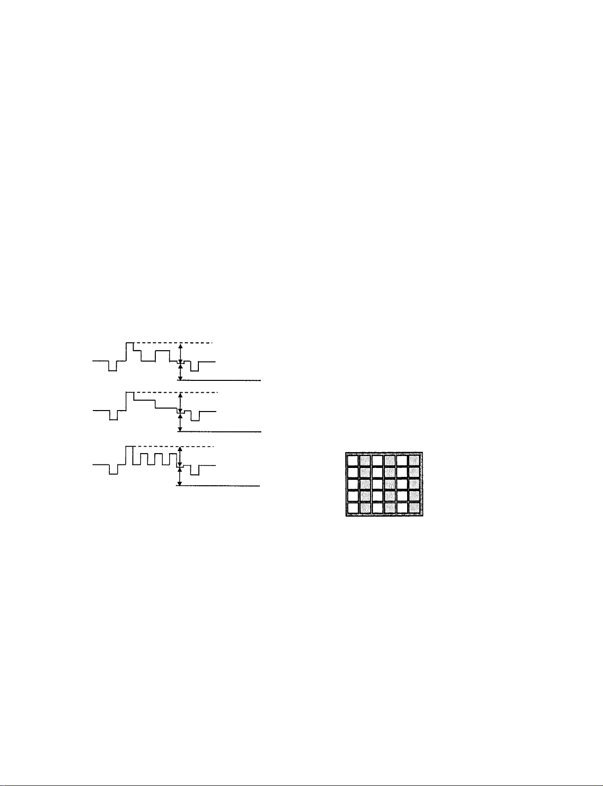
3-5. VERTICAL STRIPE ADJUSTMENT
1. Setting
D9512 TES 2 G-LUT SW 0
D9512 TPN 0 T-PA TN SW 1
D9512 TPN 1 T-SIG SEL 0
D9512 TPN 2 PATN DIR 1
D9512 TPN 3 SIG LV DIR 0
D9512 TPN 5 B-LV 15
D9512 TPN 6 G-LV 15
D9512 TPN 7 R-LV 15
2. Check the middle luminance of mono flat field on the
screen.
3. R adjustment
1) Set “D9512 TPN 8 T-PATN RGB” to 1.
2) Adjust by changing data of “LCD-DR 3 R EVEN VR” to
the vertical stripe (brightness difference ev ery two dots) to
minimum.
3) Write the data into memory.
4. G adjustment
1) Set “D9512 TPN 8 T-PATN RGB” to 2.
2) Adjust by changing data of “LCD-DR 8 G EVEN VR” to
the vertical stripe (brightness difference ev ery two dots) to
minimum.
3) Write the data into memory.
3. B adjustment
1) Set “D9512 TPN 8 T-PATN RGB” to 4.
2) Adjust by changing data of “LCD-DR 13 B EVEN VR” to
the vertical stripe (brightness difference ev ery two dots) to
minimum.
3) Write the data into memory.
Screen magnify
Should be minimize bright
difference every tw o dots.
– 28 –
Fig. 3-3
KF-50SX200/50SX200K/50SX200U
KRM-905
3-6. SUB BRIGHT ADJUSTMENT
1. Receive the monoscope signal.
2. Mode
PICTURE Personal
SCREEN Wide
3. Adjust b y changing data of “D9512 IM 3 SUB BRT” so
that the border between 0 IRE and 10 IRE becomes distinct.
4. Write the data into memory.
3-7. SCREEN CENTER ADJUSTMENT
3-7-1. Horizontal center adjustment
(1) 50Hz adjustment
1) Receive the PAL SPCB (RF) and adjust H center by
changing data of "IP00C741A 1.OACTHST-L".
2) Write the data into memory.
(2) 60Hz adjustment
1) Receive the PAL SPCB (RF) and change the picture to
PAP (Picture And Picture) mode.
2) Adjust H center by changing data of "IP00C741A
1.OA CTHST-L". At the same time conf irm no illuminated
pattern is visible on the right end of the screen. If you
should find one, change the register setting.
• Register Setting Change
6 VZOOM-L 0
7 VZOOM-H 161
8 OHCYCL-L 19
24 IACTVW-L 227
3) Write the data into memory.
3-7-2. Vertical center adjustment
(1) 50Hz adjustment
1) Receive the PAL SPCB (RF) and adjust V center by
changing data of "IP00C741A 3. SYRDLY".
2) Write the data into memory.
(2) 60Hz adjustment
*Input the NTSC monoscope (VIDEO). Adjust
"IP00C741A 3. SYRDLY" to find out the value terrible
picture flicker occurs. Note the value for 60Hz adjustment.
1) Receive the PAL SPCB (RF) and change the picture to
PIP (Picture In Picture) mode.
2) Adjust V center by changing data of "IP00C741A 3.
SYRDLY". (0 is prohibited for this register)
Be sure that ±1 step area of the noted value is prohibited.
3) Write the data into memory.
3-8. TEST -TEST MODE
Is available by pressing “OSD”, “5”, “Volume +”, “TV” button
in the standby mode, OSD “TT--”appears.
The diagnosis menu can be displayed by these methods :
TT mode : Press “33”
Service Menu : Monitoring t Error Monitor or
LCD-Engine Error Menu
For correction of any wrong input (first digit.) by mistake these
methods are possible :
Press“- -”
Press“0”
The Test-Test Mode can be left by these methods :
Press“0” twice.
Press TV button
Press standby button
00 TT mode off
01 picture maximum
02 picture minimum
03 volume = 30% (speaker and headphone)
04 volume = 50% (speaker and headphone)
05 volume = 65% (speaker and headphone)
06 volume = 80% (speaker and headphone)
07 Ageing Mode
This TT mode is stored in NVM, after power shut do wn
TV starts again in Ageing mode. Ageing Mode can be
left by pressing TV button.
Volume is set to minimum.
08 Shipping Conditions
Note : The u-controller checks all possible IC’s and
generate an internal list.
This list is the base of the error check procedure.
Production mode = off
Ignore Errors = off
Errors = cancelled
Standby = off
Parental lock = off
Ageing white = off
Flash = erased
Language = English
Country = off
AV1 = Normal, “AV1”
AV2 = Normal, “AV2”
AV3 = Normal, “AV3”
AV4 = Normal, “AV4”
AV In Main = AV1
AV In Sub = AV1
AV3 Out = TV
Main program = 1
Sub program = 2
– 29 –
KF-50SX200/50SX200K/50SX200U
KRM-905
Picture Mode = Live
AI = on
Noise reduction = AUTO
Colour Tone = Normal
volume = 35% (speaker and headphone)
All analogue values = reset (picture and sound)
Format = Smart
Sound mode = DYNAMIC
09 Enter the projector engine menu
10 No action
11 Sub picture adjustment
12 Sub colour adjustment
13 Display of software version and TV set configuration
16 Picture level 50%
17 Audio mute on
19 Sub brightness adjustment
20 No action
21 Destination A includes text settings, display TV status
22 Destination L includes text settings, display TV status
23 Destination E includes text settings, display TV status
24 Destination U includes text settings, display TV status
25 Destination D includes text settings, display TV status
26 Destination B includes text settings, display TV status
27 Destination K includes text settings, display TV status
28 Destination R includes text settings, display TV status
30 No action
32 Main H POS adjustment
Horizontal center adjustment for MID-X
input.Adjustment is done with left and right joystick
button, released by “TV” or “OK” button
33 Error monitor
35 Production monitor
39 No action (AE2 dealer commander)
40 No action
41 Screen Mode Check
TV set is toggling automatically screen modes
(4:3,14:9,zoom, zoom upwards)
46 Reserved for dealer commander
47 Reinitialize NVM (program 99)
48 Set NVM as non virgin:
49 Set NVM as virgin:
After next power on the complete NVM (except chan-
nel tables) are overwritten.
50 No action
59 Copy external NVM on service connector to internal
NVM
60 No action
61 Service Mode
62 Productions Mode
63 Copy the picture reset from ROM into the picture reset
location of NVM.
64 Copy the actual adj. Picture data from NVM into the
picture reset location of NVM.
65 Reset error codes
68 Ignore errors on
69 Ignore errors off
70 No action
71 Copy default data of PANORAMA/external PLL/MID/
MID-X from ROM into NVM.
73 Clear all programs except program 1-5 and all station
labels
77 Picture Booster check
78 No video blanking
80 No action
81 Smart Link test signal on AV3 Pin10
83 Balance left/right
84 Switch Main/Center
85 Special Picture mode (set personal pict. Mode, set
brightness to 50%, set picture to 80%)
87 Personal ID reset
Personal ID is rest and initialized with “-” (program99)
88 Parental lock off
89 OSD mute on/off
90 No action
94 PIP mode test command, released by OK or 00.
99 Speaker check, released by OK or 00.
– 30 –
 Loading...