

Sony KF-50SX100, KF-50SX100K, KF-50SX100U Service Manual
LE-3SERVICE MANUAL
CHASSIS
MODEL COMMANDER DEST. CHASSIS NO.
–––––––– ––––––––––––––– –––––– ––––––––––––––
KF-50SX100 RM-903 AEP SCC-P59A-A
KF-50SX100K RM-903 OIRT SCC-P60A-A
KF-50SX100U RM-903 UK SCC-P61A-A
MODEL COMMANDER DEST. CHASSIS NO.
–––––––– ––––––––––––––– –––––– ––––––––––––––
VIDEO TV
1
2
3
4
5
6
7
8
9
0
OK
PROGR
MENU
RM
903
SONY
TV
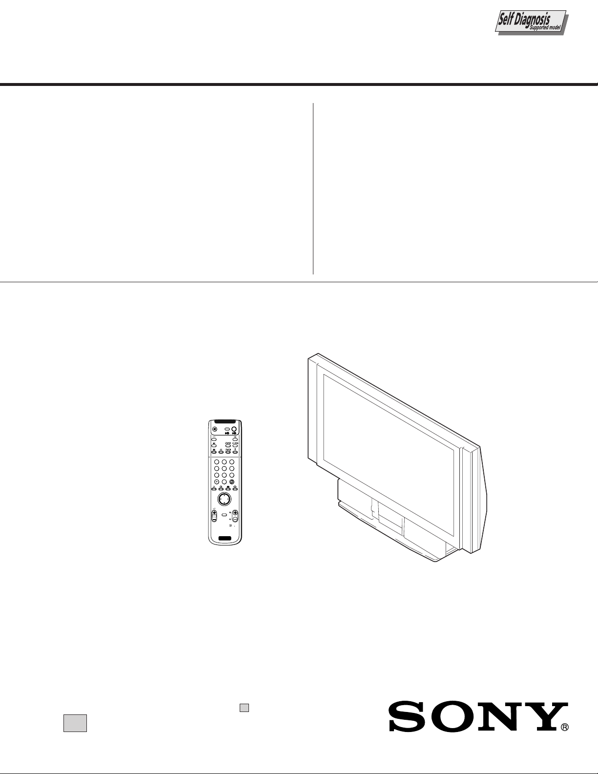
RM-903
KF-50SX100/50SX100K/50SX100U
LCD PROJECTION TV
∗ Please file according to model size. .......
50
KF-50SX100/50SX100K/50SX100U
RM-903RM-903 RM-903
SPECIFICATIONS
– 2 –
KF-50SX100/50SX100K/50SX100U
SELF DIAGNOSIS FUNCTION
1-1. LE-3 SELF DIAGNOSTIC SOFTWARE
The identification of errors within the LE-3 chassis is triggered in one of two ways : - 1: Busy or 2: Device failure to respond to IIC. In
the event of one of these situations arising the software will first try to release the bus if busy (Failure to do so will report with
continuous flashing LED) and then communicate with each device in turn to establish if a device is faulty. If a device is found to be
faulty the relevant device number will be displayed through the LED (Series of flashes which must be counted) See table 1., non fatal
errors are reported using this method.
RM-903RM-903 RM-903
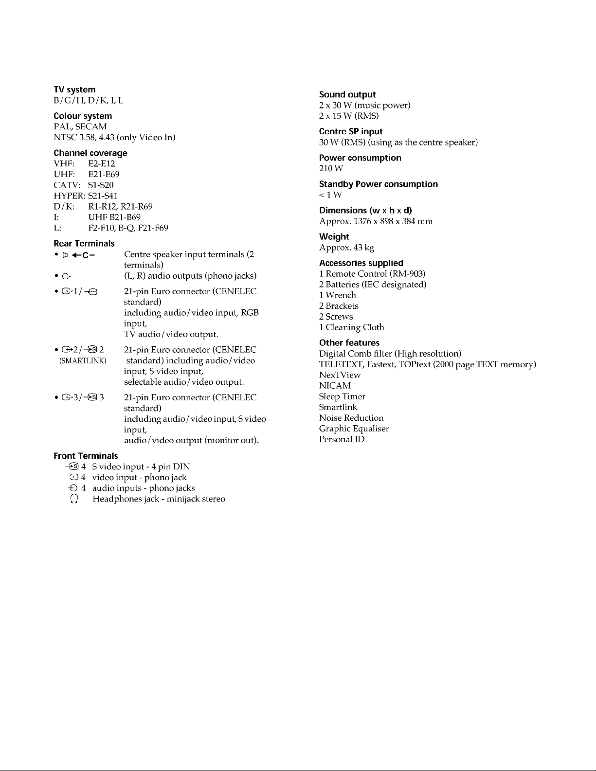
Diagnostic Item
Description
Power does not turn on Does not light
SET 5V Dowin 2 times
No. of times Standby
LED Flashes
ERROR STBY LED ERROR COUNT
No error 00
Not allowed (may be confused with Sircs response flash) 01
SET 5V Down 02
Lamp Cover error 03
Fan error 04
Lamp Driver error 05
Not used 06
Speaker Protection 07
General IIC Line 0 error 08
MEGATEXT (IC9502) 09
NVM (IC9108) 10
Main colour decoder (IC8301) 11
MCP (IC701) 14
Multi sound processor (IC4702) 15
Auto Wide (IC8700) 16
External RAM (IC9107) 17
Lamp error Lamp LED continnously on
Probable cause Location
Power cord is not plugged in
Fuse is Burned out
Q1606, 1607 Power FET is shorted Power does not come on
(G Board) Load on power line has shorted
Detected Symptoms
Power does not come on
No power is supplied to the TV
AC power supply is faulty
Flash Timing Example : e.g. error number 3
ON
OFF OFF
ON ONStandby LED
– 3 –
KF-50SX100/50SX100K/50SX100U
RM-903RM-903 RM-903
1-2. ERROR DETECTION MONITOR
Device acknowledge is used to check IIC errors.
Each device is checked three times, if there is no acknowledge after every attempt, it will be regarded as an error.
There are three step to check errors.
1. IIC line 0
If all devices except the NVM have errors, IIC line 0 error is displayed.
2. Each device check
if IIC line error and board error are not detected then the device with an error is displayed.
The detected errors can be displayed as follows:
1. Error Monitor Menu
2. Error Reader
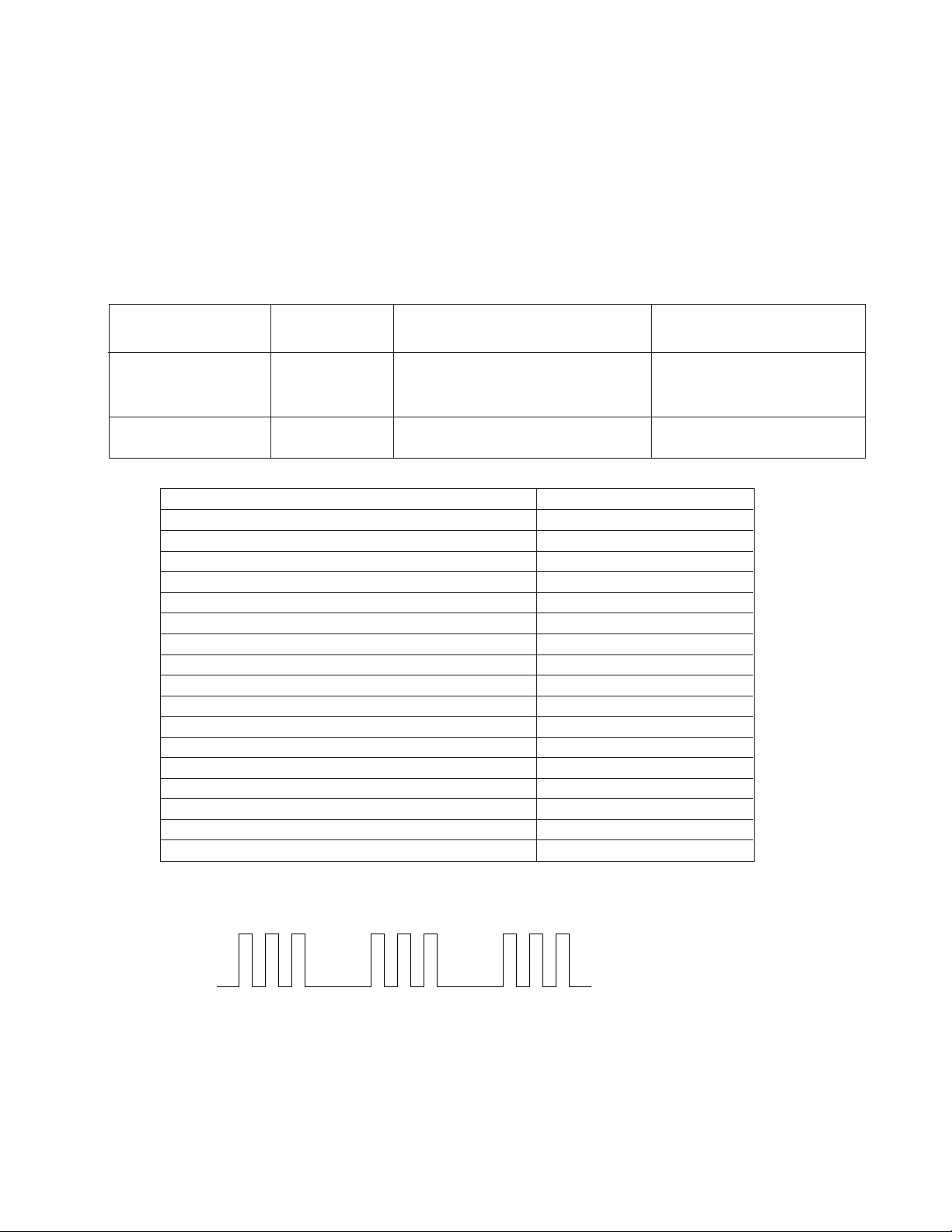
1-2-1. Error Monitor Menu
The error monitor menu is displayed by selecting Service mode : Monittoring. The following menu will be displayed:
Error Monitor
Ignore Errors OFF
1
Operating Time :
Stored Errors :
1. J-B MSP3410
2. B3-B CXA2101 MCP
3. J-B CXA2123 Main Col Dec
4. Error Code Not Valid
5. Error Code Not Valid
Current Error :
Start Error Sequence
000021 h 40 min
Error Monitor
1 LAMP : 0
5 LAMP DRIVER : 0
4FAM : 0
3 LAMP COVER : 1
WDT-E : 0
ON ON
Error Monittor
LCD-Engine error menu
– 4 –
KF-50SX100/50SX100K/50SX100U
1-2-2. Error Reader Display
The error reader display is connected to the service connector to read actual error codes. The part number for the error reader display is
S-188-900-10.
Once an error has been detected it will then be displayed on the two digit error reader. The errors displayed refer to the following table:
Send Data to Error Reader
Error Code Data High Data Low Error Type Function
00 00h – f0h no device
Gen. IIC Error
00 01h f0h 01h IIC 0 line
00 02h f0h 02h IIC 1 line not used
Device Error
A Board
01 01h f1h 01h CXA1875 Port Expander
01 02h f1h 02h TU1301 Main Tuner
01 03h f1h 03h TU1302 Sub Tuner
BB Board
04 01h f4h 01h CXD9509 MID-X
BB Board
06 01h f6h 01h CXA2101 MCP
J Board
04 04h f4h 04h TDA9178 Picture Booster
07 03h f7h 03h CXA2123 Sub Colour
07 04h f7h 04h CXA2123 Main Colour
07 0Ah f7h 0Ah CXA2149 AV SW
S Board
07 05h f7h 05h CXA1875 Sub Sound
07 08h f7h 08h MSP3410D Sound Proc
M Board
08 01h f8h 01h ST24C32 NVM
RM-903RM-903 RM-903
– 5 –

KF-50SX100/50SX100K/50SX100U
RM-903RM-903 RM-903
TABLE OF CONTENTS
Section Title Page
–––––– –––– ––––
SELF DIAGNOSIS FUNCTION ............................................ 3
1. GENERAL
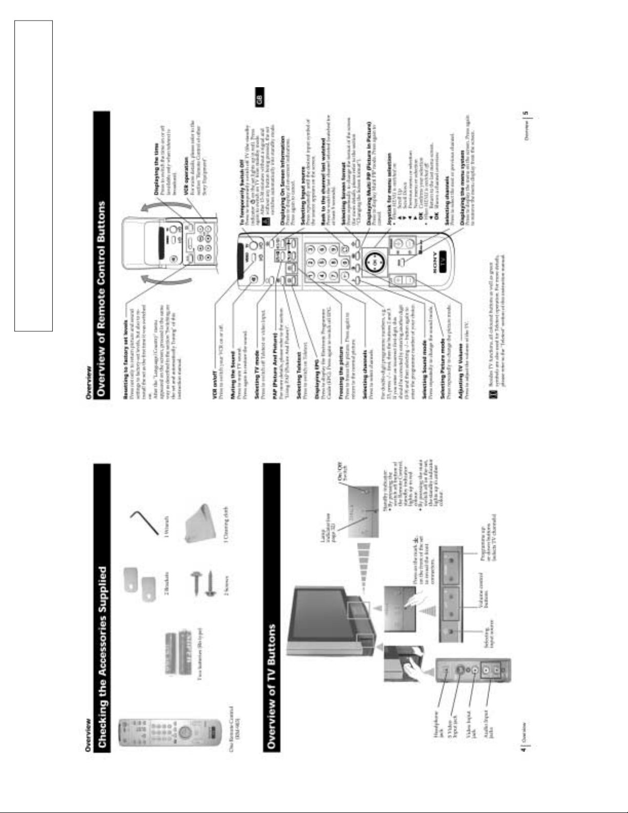
Overview ................................................................................. 8
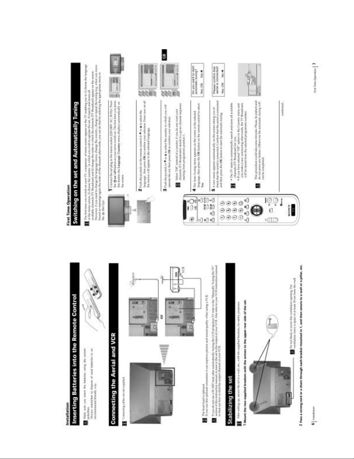
Installation ............................................................................... 9
First Time Operation ............................................................... 9
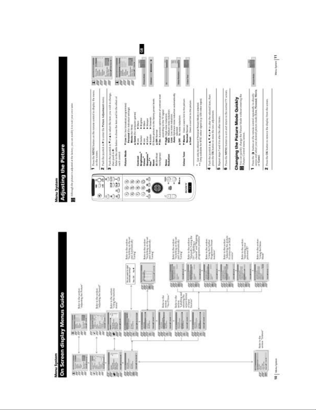
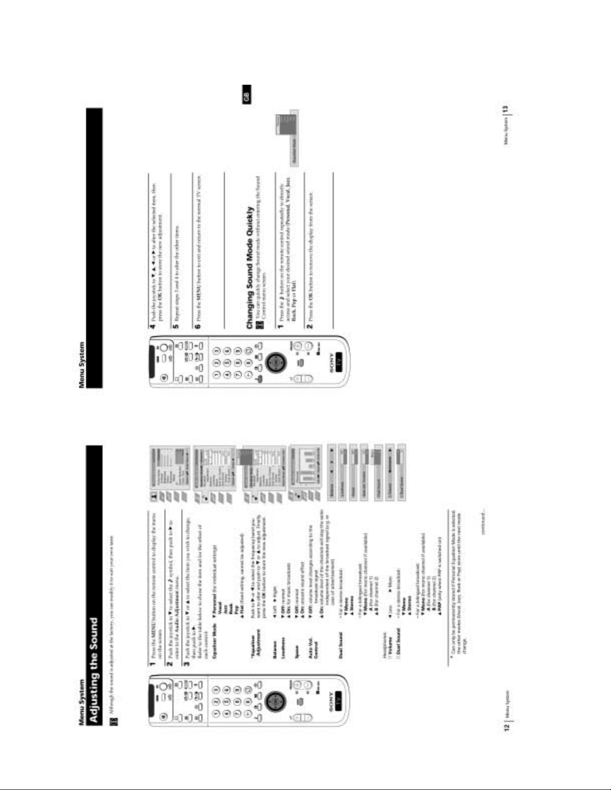
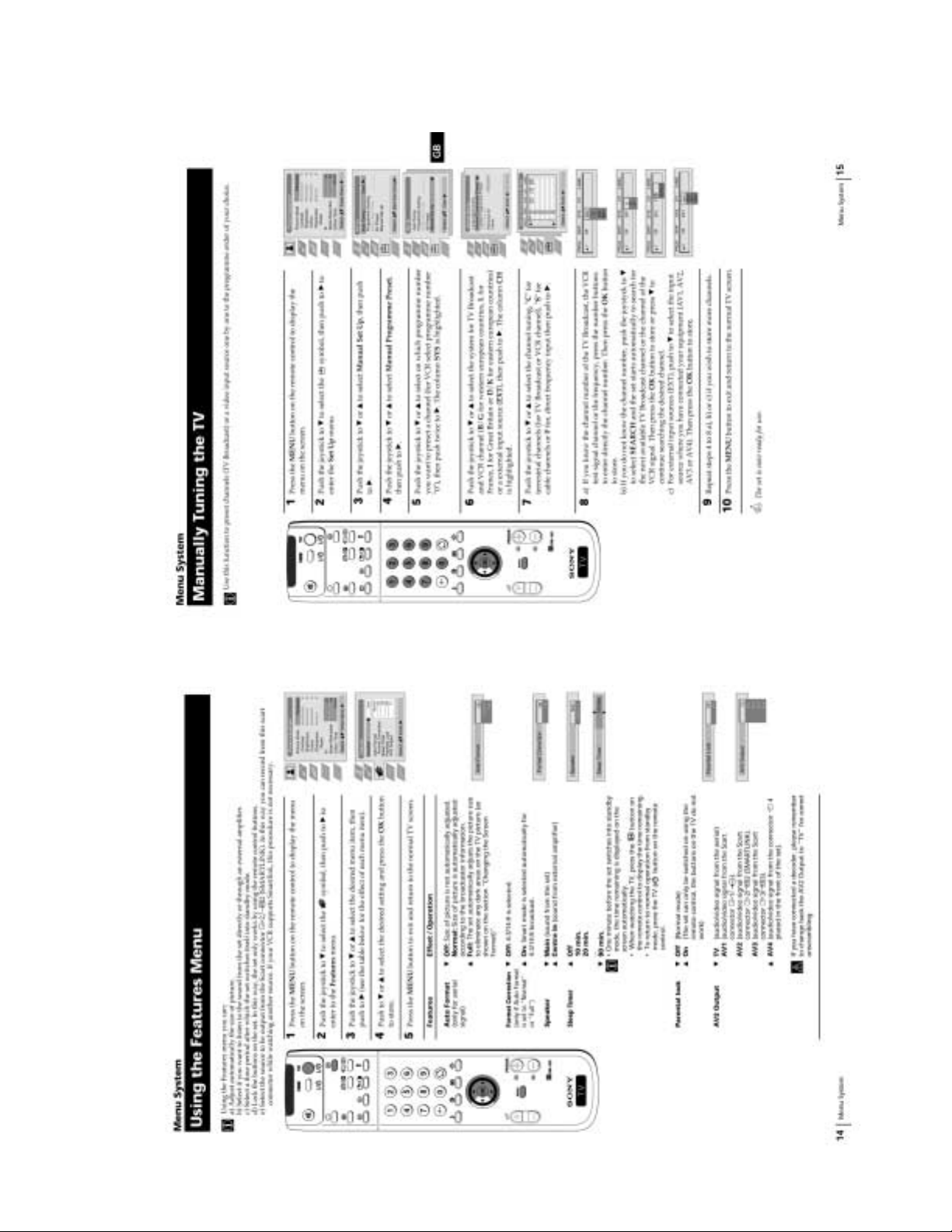
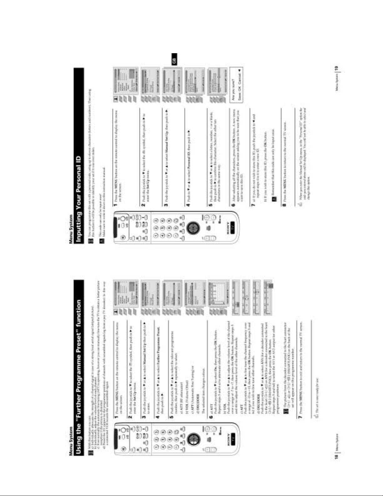
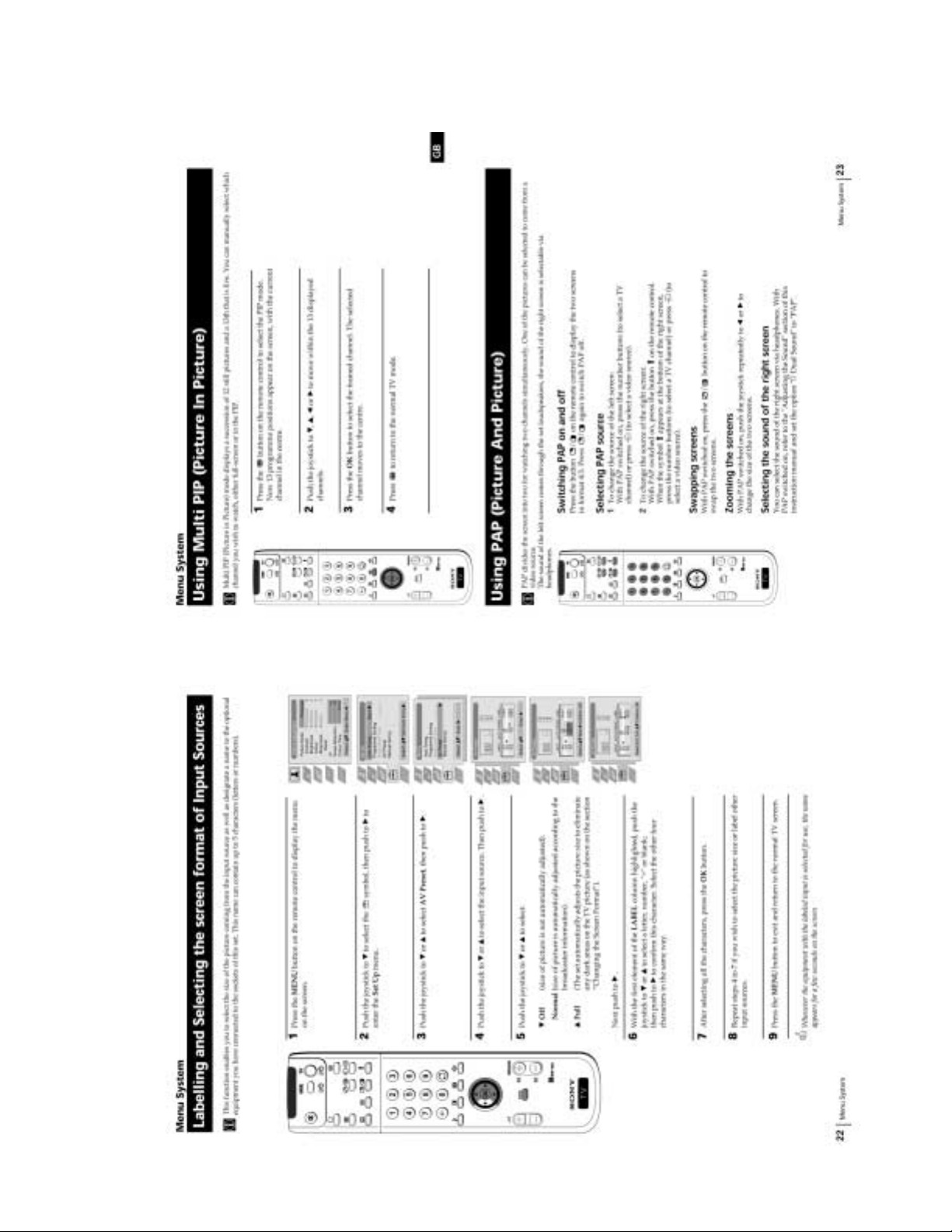
Menu System ......................................................................... 10
Teletext .................................................................................. 18
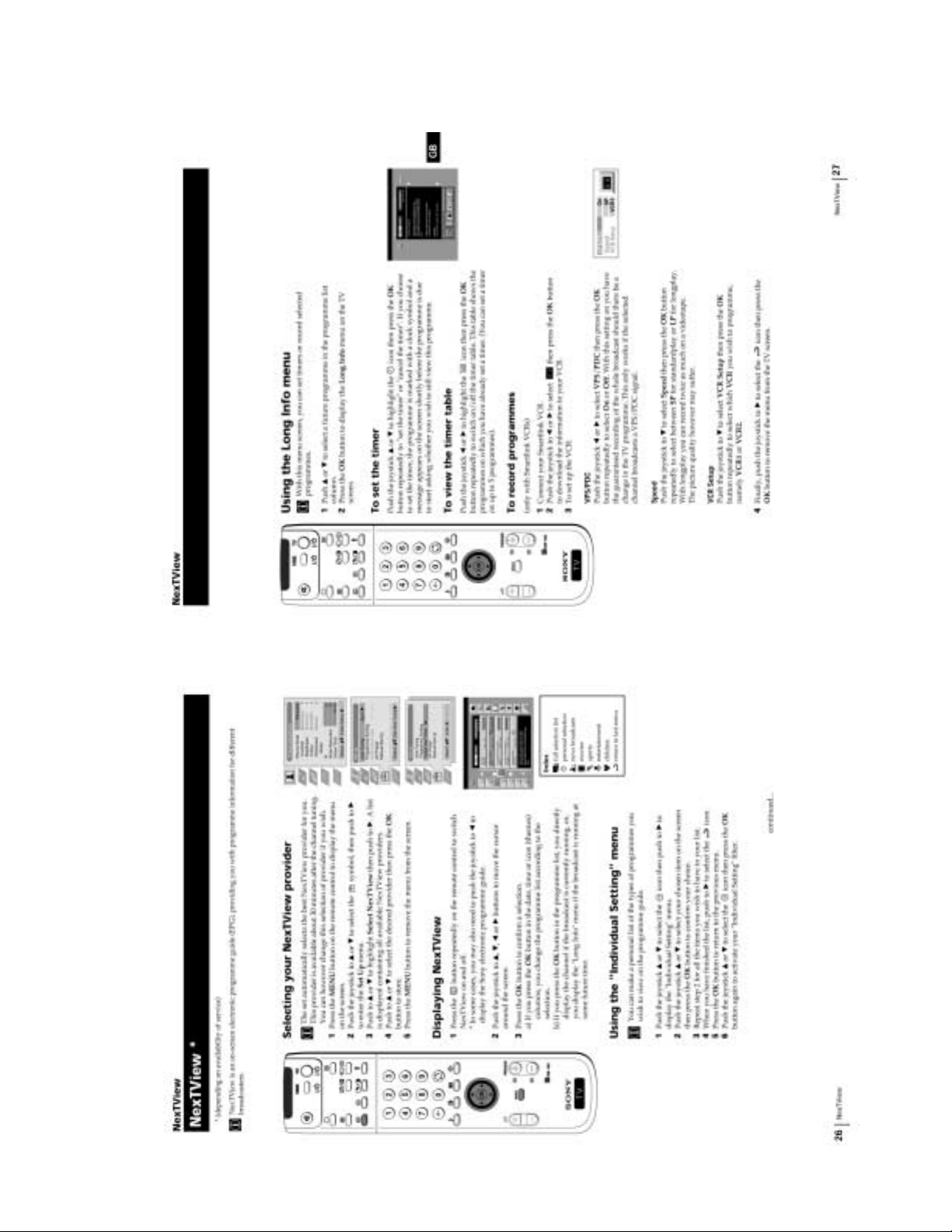
NexTView ............................................................................. 19
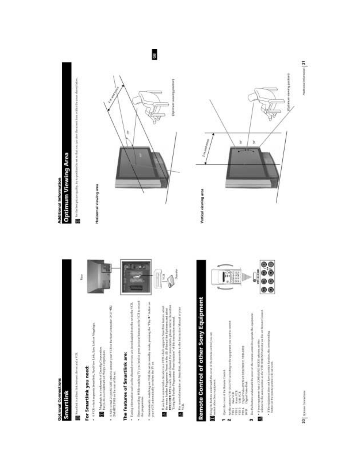
Optional Connections ............................................................ 20
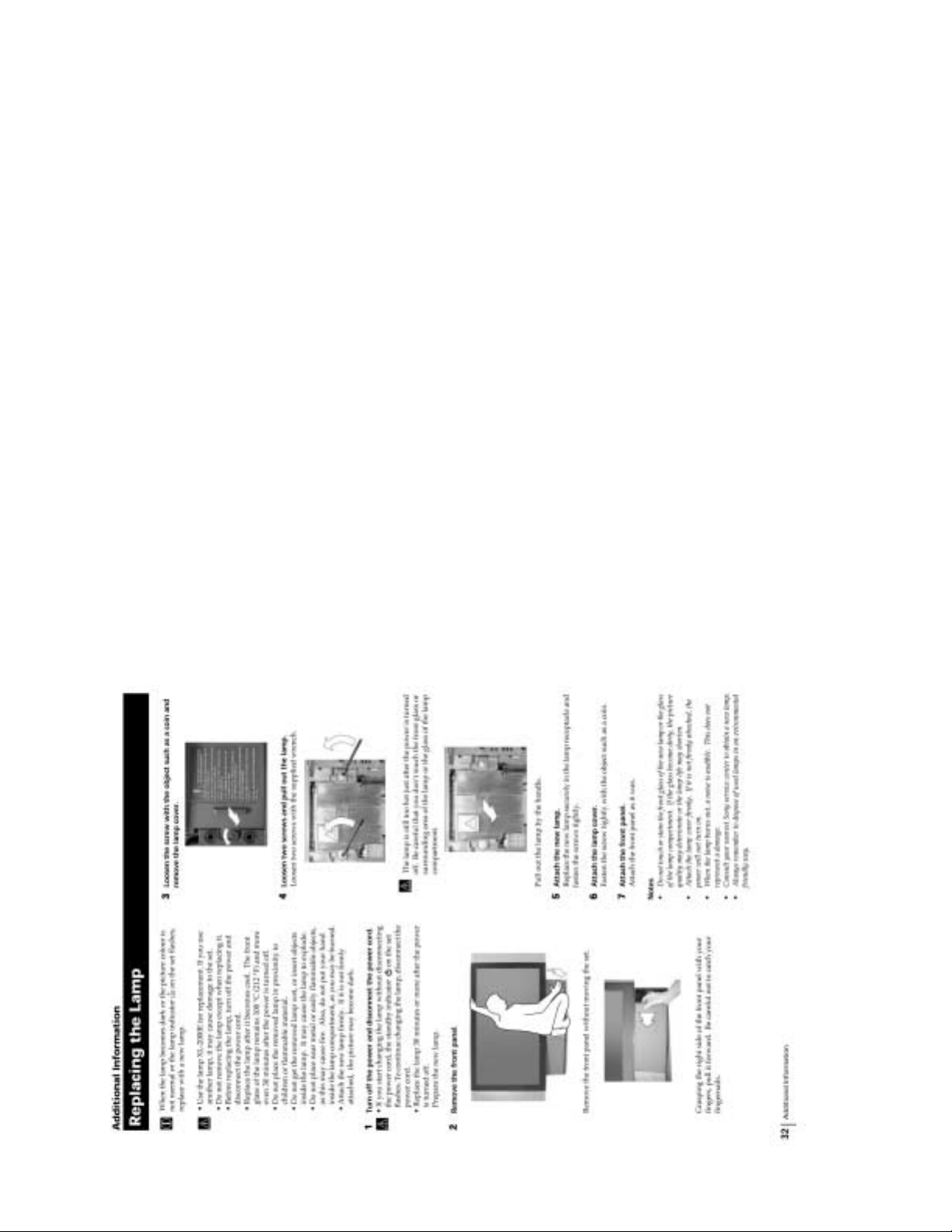
Additional Information .......................................................... 21
2. DISASSEMBLY
2-1. Rear Cover Assembly ................................................ 23
2-2. Service Position ......................................................... 23
2-3. OU Bracket Removal ................................................ 23
2-4. Duct Block Assembly................................................ 23
2-5. Power Block .............................................................. 24
2-6. Optical Unit Block Assembly.................................... 24
2-7. J Board Removal ....................................................... 25
2-8. M, BD, S, N Board Removal .................................... 25
2-9. T Board ...................................................................... 25
2-10. A Board Removal ...................................................... 25
2-11. G Block Assembly Removal ..................................... 26
2-12. G Board Removal ..................................................... 26
2-13. Front Cover Removal ................................................ 26
2-14. Control Panel Block Assembly Removal .................. 26
2-15. H4 Board Removal ................................................... 27
2-16. H2 Board Removal ................................................... 27
2-17. Screen, Mirror Block Assembly ................................ 27
2-18. Mirror Cover Block Assembly Removal ................... 27
2-19. Contrast Screen, Diffusion Plates Removal .............. 28
2-20. Squawker Block Assemblies, Woofer Block
Assembly Removal ................................................... 28
2-21. Speaker Removal ...................................................... 29
2-22. Mirror Removal ......................................................... 29
2-23. H1 Board Removal .................................................... 29
3. ELECTRICAL ADJUSTMENTS
3-1. Adjustment With Commander................................... 30
3-2. LCD Projecter Engine ............................................... 42
3-3. Sub Colour Adjustment ............................................. 42
3-4. RGB Output Level Adjustment................................. 43
3-5. Vertical Stripe Adjustment ........................................ 43
3-6. Sub Bright Adjustment .............................................. 43
3-7. Screen Center Adjustment ......................................... 44
3-8. Test-Test Mode .......................................................... 44
Section Title Page
–––––– –––– ––––
4. DIAGRAMS
4-1. Block Diagram (1) ..................................................... 47
Block Diagram (2) ..................................................... 50
Block Diagram (3) ..................................................... 53
Block Diagram (4) ..................................................... 57
Block Diagram (5) ..................................................... 61
Block Diagram (6) ..................................................... 61
Block Diagram (7) ..................................................... 64
4-2. Frame Schematic Diagrams ...................................... 67
4-3. Circuit Boards Location ............................................ 70
4-4. Printed Wiring Boards and Schematic Diagrams ...... 70
• A Board ................................................................... 71
• BB (1/4) Board ....................................................... 81
• BB (2/4) Board ....................................................... 85
• BB (3/4) Board ....................................................... 89
• BB (4/4) Board ....................................................... 93
• M (1/2) Board ......................................................... 97
• M (2/2) Board ....................................................... 101
• J (1/2) Board ......................................................... 109
• J (2/2) Board ......................................................... 113
• H1 Board ............................................................... 117
• T Board ................................................................. 117
• H2 Board ............................................................... 118
• H4 Board ............................................................... 119
• N Board ................................................................. 120
• S Board ................................................................. 125
• G Board ................................................................. 127
4-5. Semiconductors ....................................................... 132
5. EXPLODED VIEWS
5-1. Mirror Section ......................................................... 134
5-2. Screen Section ......................................................... 135
5-3. Cabinet Section ....................................................... 136
5-4. Optical Unit Section ................................................ 137
5-5. Chassis Section ........................................................ 138
6. ELECTRICAL PARTS LIST ...................................... 139
– 6 –

(CAUTION)
SHORT CIRCUIT THE ANODE OF THE PICTURE TUBE AND THE
ANODE CAP TO THE METAL CHASSIS, CRT SHIELD, OR CAR-
BON PAINTED ON THE CRT, AFTER REMOVING THE ANODE.
WARNING!!
AN ISOLATION TRANSFORMER SHOULD BE USED DURING
ANY SERVICE TO AVOID POSSIBLE SHOCK HAZARD, BECAUSE OF LIVE CHASSIS.
THE CHASSIS OF THIS RECElVER IS DIRECTLY CONNECTED
TO THE AC POWER LINE.
SAFETY-RELATED COMPONENT WARNING!!
COMPONENTS IDENTIFIED BY SHADING AND MARK ! ON THE
SCHEMATIC DIAGRAMS, EXPLODED VIEWS AND IN THE
PARTS LIST ARE CRITICAL TO SAFE OPERATION. REPLACE
THESECOMPONENTS WITH SONY PARTS WHOSE PART NUMBERS APPEAR AS SHOWN IN THIS MANUAL OR IN SUPPLEMENTS PUBLISHED BY SONY. CIRCUIT ADJUSTMENTS THAT
ARE CRITICAL TO SAFEOPERATION ARE IDENTIFIED IN THIS
MANUAL. FOLLOW THESE PROCEDURES WHENEVER CRITICAL COMPONENTS ARE REPLACED OR IMPROPER OPERATION IS SUSPECTED.
KF-50SX100/50SX100K/50SX100U
RM-903RM-903 RM-903
– 7 –
The operating instructions mentioned here are partial abstracts from the
Operating Instructions Manual. The page numbers of the Operating
Instruction Manual remain as in the manual. (Part no : 4-078-836-11)
GENERAL
SECTION 1
– 8 –
– 9 –

– 10 –
– 11 –
– 12 –
– 13 –

– 14 –
– 15 –

– 16 –
– 17 –

– 18 –
– 19 –

– 20 –
– 21 –
– 22 –

SECTION 2
DISASSEMBLY
KF-50SX100/50SX100K/50SX100U
RM-903RM-903 RM-903
2-1. REAR COVER ASSEMBLY
2 Rear cover assembly
1 Eleven screws
(+BVTP 4 X 16)
2-2. SERVICE POSITION
1
2-3. OU BRACKET REMOVAL
2-4. DUCT BLOCK ASSEMBLY
1 Remove the lamp
2 OU bracket
3 Connector
1 Five screws
(+BVTP 4 X 16)
4 Duct block
assembly
2 Screw
(+BVTP 4 X 16)
– 23 –
KF-50SX100/50SX100K/50SX100U
RM-903RM-903 RM-903
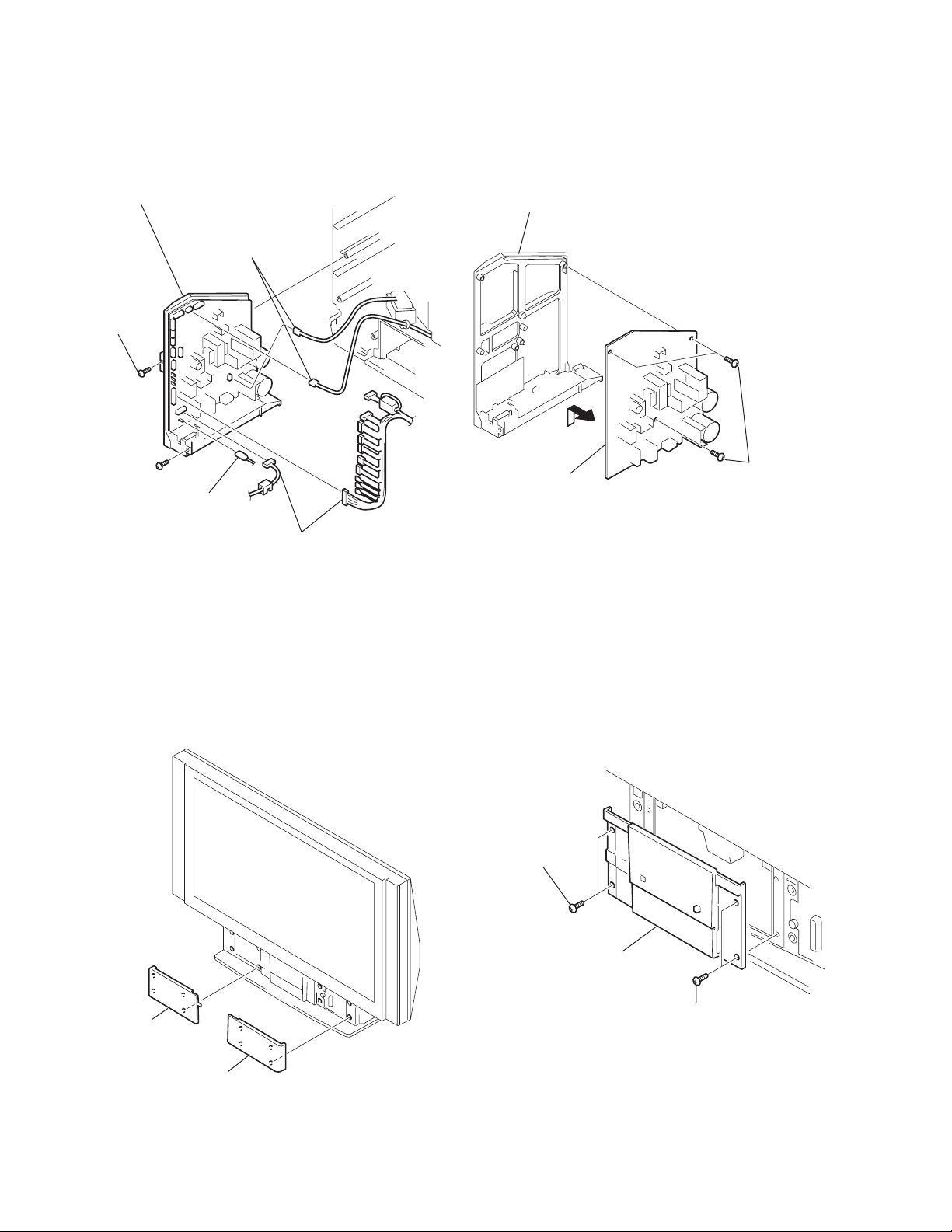
2-5. POWER BLOCK
3 Four screws
(+BVTP 3 X 12)
2 Two screws
(+BVWHTP 3 X 12)
1 Connector
4 Power block
2-6. OPTICAL UNIT BLOCK ASSEMBLY
1 Fasten tags
2 Connector
1 Fasten tag
4 Loosen cables
3 Conectors
Note: Be careful about the no dust or dirt are on the surface
contacts the optical unit block assembly.
• Clean the periphery of the set.
• Clean the periphery of the optical unit block assembly in
the set (the inside of the control panel, the surface contacts
between the optical unit block assembly and the bottom
cabinet and periphery).
q; Optical unit block assembly
9 Connectors
8
7 Two screws
(+P 4 X 35)
6 Connectors
5
4 Two screws
(+BVTP 4 X 16)
– 24 –

KF-50SX100/50SX100K/50SX100U
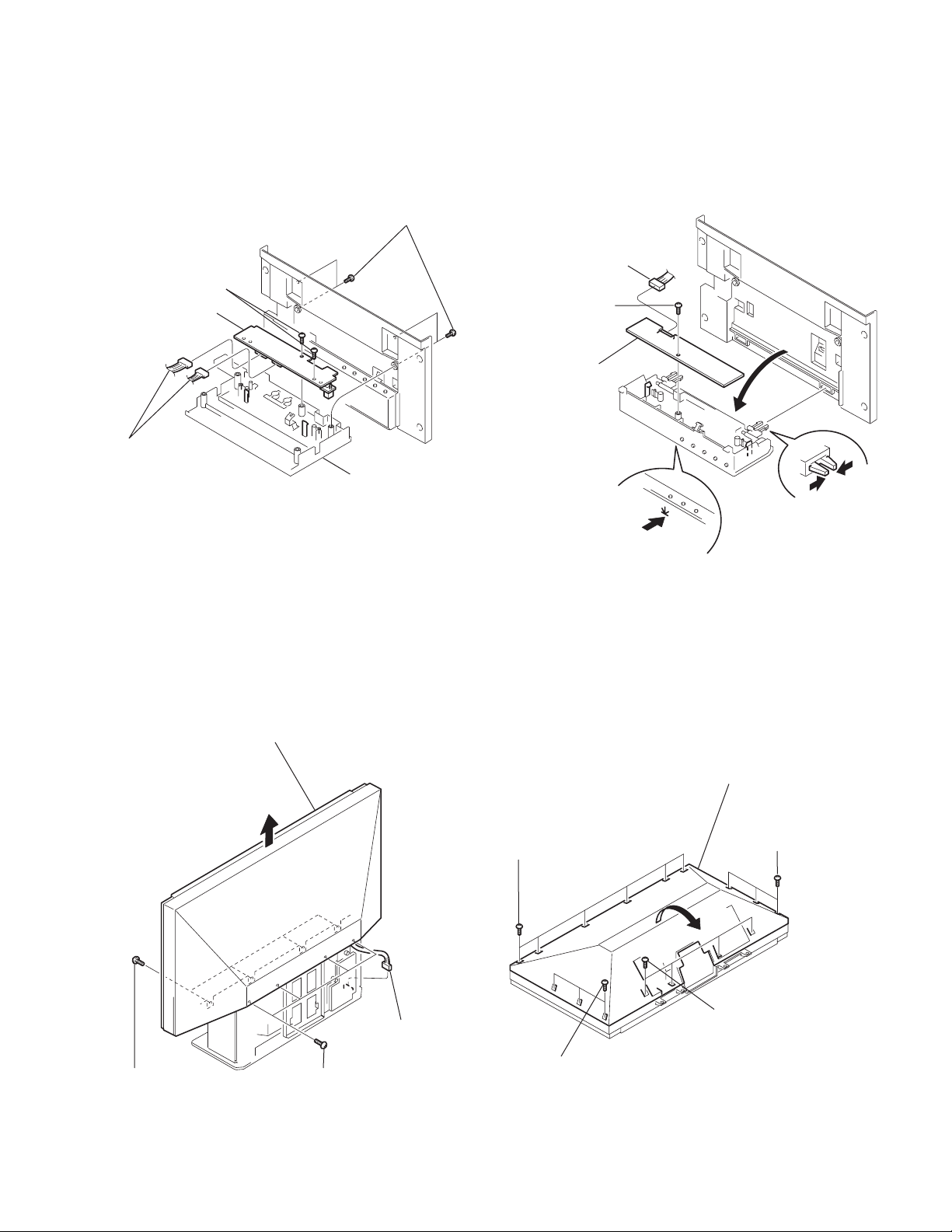
2-7. J BOARD REMOVAL 2-8. M, BD, S, N BOARDS REMOVAL
RM-903RM-903 RM-903
1 Connectors
6 Shield
cover J
5
2 Two screws
(+BVTP 3 X 12)
3 Three screws
(+BVTP 4 X 16)
4 Bracket J
2 BB board
2 M board
A board
3 S board
4 N board
2-9. T BOARD
1 Remove the optical block assembly
4 T board
3 Screw
(+BVTP 3 X 12)
2 Connectors
2-10. A BOARD REMOVAL
1 Fasten tag
2 Connector
2 Connectors
3 Claws
2 RF cable
2 Connectors
4 A board
2 Connectors
– 25 –
KF-50SX100/50SX100K/50SX100U
RM-903RM-903 RM-903
2-12. G BOARD REMOVAL2-11. G BLOCK ASSEMBLY REMOVAL
5 G block assembly
1 Two screws
(+BVTP 4 X 16)
2 Fasten tag
4 Connectors
3 Connectors
G bracket
3 G board
2
1 Three screws
(+BVTP 4 X 16)
2-13. FRONT COVERS REMOVAL
Front cover L
Front cover R
2-14. CONTROL PANEL BLOCK ASSEMBLY
REMOVAL
1 Two screws
(+BVTP 4 X 16)
2 Control panel
block assembly
1 Two screws
(+BVTP 4 X 16)
– 26 –
KF-50SX100/50SX100K/50SX100U
4 Screw
(+BVTP 3 X 12)
6 H2 board
5
2
1
3 Connector
2-15. H4 BOARD REMOVAL 2-16. H2 BOARD REMOVAL
1 Four screws
(+BVTP 4 X 16)
3 Two Screws
(+BVTP 3 X 12)
4 H4 board
2 Connector
Indication panel
assembly
RM-903RM-903 RM-903
2-17. SCREEN, MIRROR BLOCK ASSEMBLY
Screen mirror block assenbly
1 Four Screws
(+BVTP 4 X 16)
4
3 Connector
2 Four screws
(+BVTP 4 X 16)
2-18. MIRROR COVER BLOCK ASSEMBLY
REMOVAL
Mirror cover block assembly
1 Six screws
(+BVTP 4 X 16)
2
1 Four screws
(+BVTP 4 X 16)
1 Three screws
(+BVTP 4 X 16)
1 Three screws
(+BVTP 4 X 16)
– 27 –
KF-50SX100/50SX100K/50SX100U
RM-903RM-903 RM-903
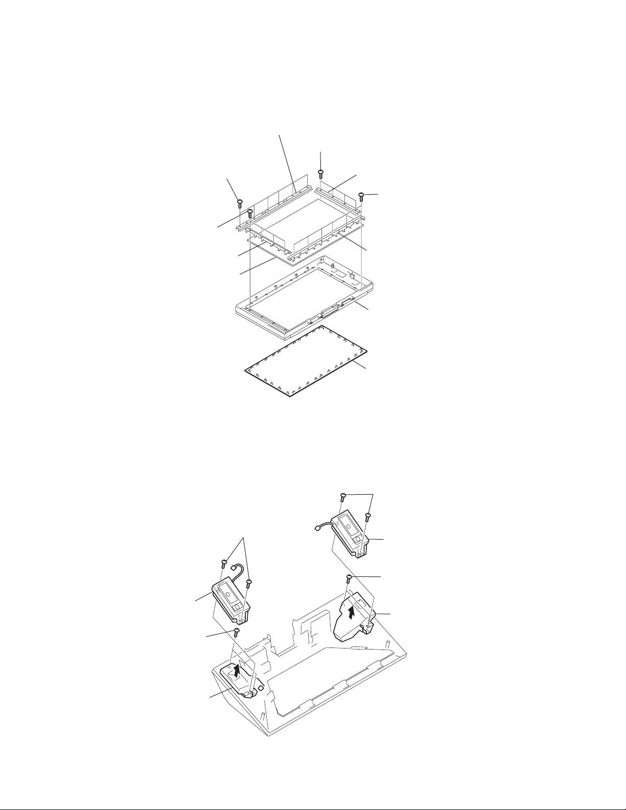
2-19. CONTRAST SCREEN, DIFFUSION PLATES REMOVAL
1 Six screws
(+BVTP 4 X 16)
1 Four screws
(+BVTP 4 X 16)
2 Screen holder (S)
3 Diffusion plates
2 Screen holder (L)
1 Four screws
(+BVTP 4 X 16)
2 Screen holder (S)
1 Six screws
(+BVTP 4 X 16)
2 Screen holder (L)
Screen frame assembly
4 Contrast screen
2-20. SQUAWKER BLOCK ASSEMBLIES, WOOFER BLOCK ASSEMBLY REMOVAL
1 Two screws
(+BVTP 4 X 16)
5 Two screws
(+BVTP 4 X 16)
6 Squawker
block (R)
assembly
7 Two screws
(+BVTP 4 X 16)
2 Squawker block (L)
assembly
3 Two screws
(+BVTP 4 X 16)
4 Woofer block (L)
assembly
8 Woofer block
(R) assembly
– 28 –
KF-50SX100/50SX100K/50SX100U
RM-903RM-903 RM-903
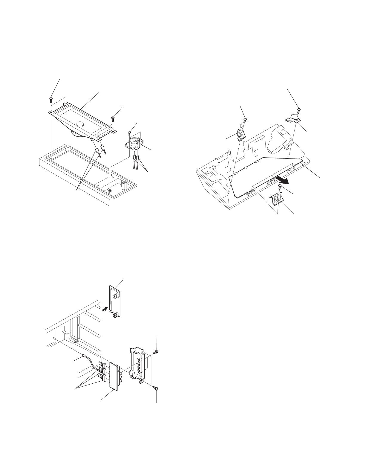
2-21. SPEAKERS REMOVAL
1 Two screws (+BVTP 4 X 16)
3 Speaker (13 X 7cm)
5 Fasten tags
1 Two screws
(+BVTP 4 X 16)
4 Two screws
(+BVTP 3 X 12)
6 Speaker
(2cm)
5 Fasten tags
2-22. MIRROR REMOVAL
1 Two screws
(+BVTP 4 X 16)
5 Two screws
(+BVTP 4 X 16)
6 Mirror
holder (R)
2 Mirror
holder (L)
7 Mirror
3 Screw
(+BVTP 4 X 16)
4 Mirror holder (U)
2-23. H1 BOARD REMOVAL
3 Fasten tag
4 Connectors
6 H1 board
1 H1 lid
1 Two screws
(+BVTP 3 X 8)
1 Two screws
(+BVTP 4 X 16)
– 29 –
KF-50SX100/50SX100K/50SX100U
RM-903RM-903 RM-903
ELECTRICAL ADJUSTMENTS
SECTION 3
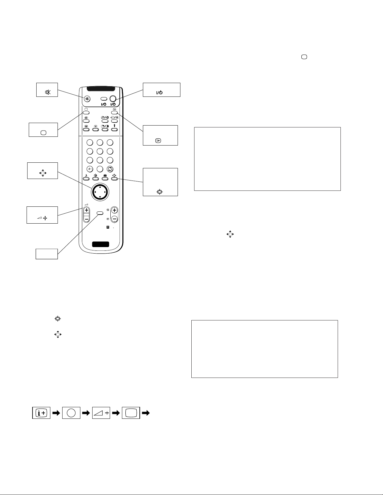
3-1. ADJUSTMENTS WITH COMMANDER
Service adjustment to this model can performed with the supplied
remote commander RM-903.
MUTE
TV MODE
JOYSTICK
VOLUME +
MENU
1
4
7
2
5
8
0
OK
MENU
SONY
TV
VIDE O TV
3
6
9
PROGR
RM
903
TV STANDBY
ON SCREEN
DISPLAY
SCREEN
FORMAT
4:3/16:9
RM-903
3. Press “-” + “-” on the commander. If “ (TV MODE)”
button is pressed, the set exits from the TT mode and returns to
normal TV mode.
3-1-2. How to Enter Service Menu
1. Select TT mode.
2. Press “MENU” button on the commander once, and normal
menu screen will appear, or press it once more, and the follow-
ing service menu screen will appear.
Service AE5(A)
Initialising
Reset Devices
Monitoring
Device Register Setting
Special Adjustment
Select : v V Next menu : B
3. Following the screen, press v or V key on the joystick to se-
lect the desired item, and press B key to enter the selected
item.
4. Press v or V key on the joystick to change data of each item,
and press “
(OK)” button to write changed data.
(Except Projector Engine mode)
5. To return from each item, press b key on the joystick. Or, to
return to the TT mode, press the “MENU” button.
(Except Projector Engine mode)
1. Selection of Mode Between PAL and NTSC
PAL mode : Enter PAL signal with color burst.
NTSC mode: Enter NTSC signal with color burst. (VIDEO
input only)
2. Selection of Screen Format
1) Press “
(BLUE)” button on the commander.
2) Press v or V key on the joystick to select screen format and
press “
(OK)” button. At this time, normal screen comes
back. (In the TT mode, the menu is switched to the Service
menu.)
3-1-1. How to Enter TT Mode
1. Turn on the main power switch to place this set in standby
mode. (LED will light in red.)
2. Press the buttons on commander as follows, and the TT
mode will be selected.
Enter the
“TT MODE”
(
DISPLAY
5
(DIGIT 5) (VOLUME +) (TV MODE)ON SCREEN
)
“TT - -” will appear in the top right corner of the screen.
Other status information will also be displayed.
3-1-3. Screen Display for Service Menu
If each item of service menu is selected, the following screen is
displayed.
• Initialising
Initialising
Model Setting
Destination Setting
Basic Setting
Feature Setting
Select : v V Next menu : B
– 30 –
 Loading...