

Sony KE-42XBR900 Schematic
MODIFICATION
No. DATA CONTENTS
1
2003. 2 Addition of Disassembly, Adjustments, Troubleshooting and Diagrams
HISTORY
MODEL NAME : KE-42XBR900
SERVICE MANUAL
P ARTS No. : 9-978-755-02
* Blue characters are linking.
(P.1-1, P.2-1, P.3-1, P.4-1)
Revised all pages for Exploded Views (P.5-1)
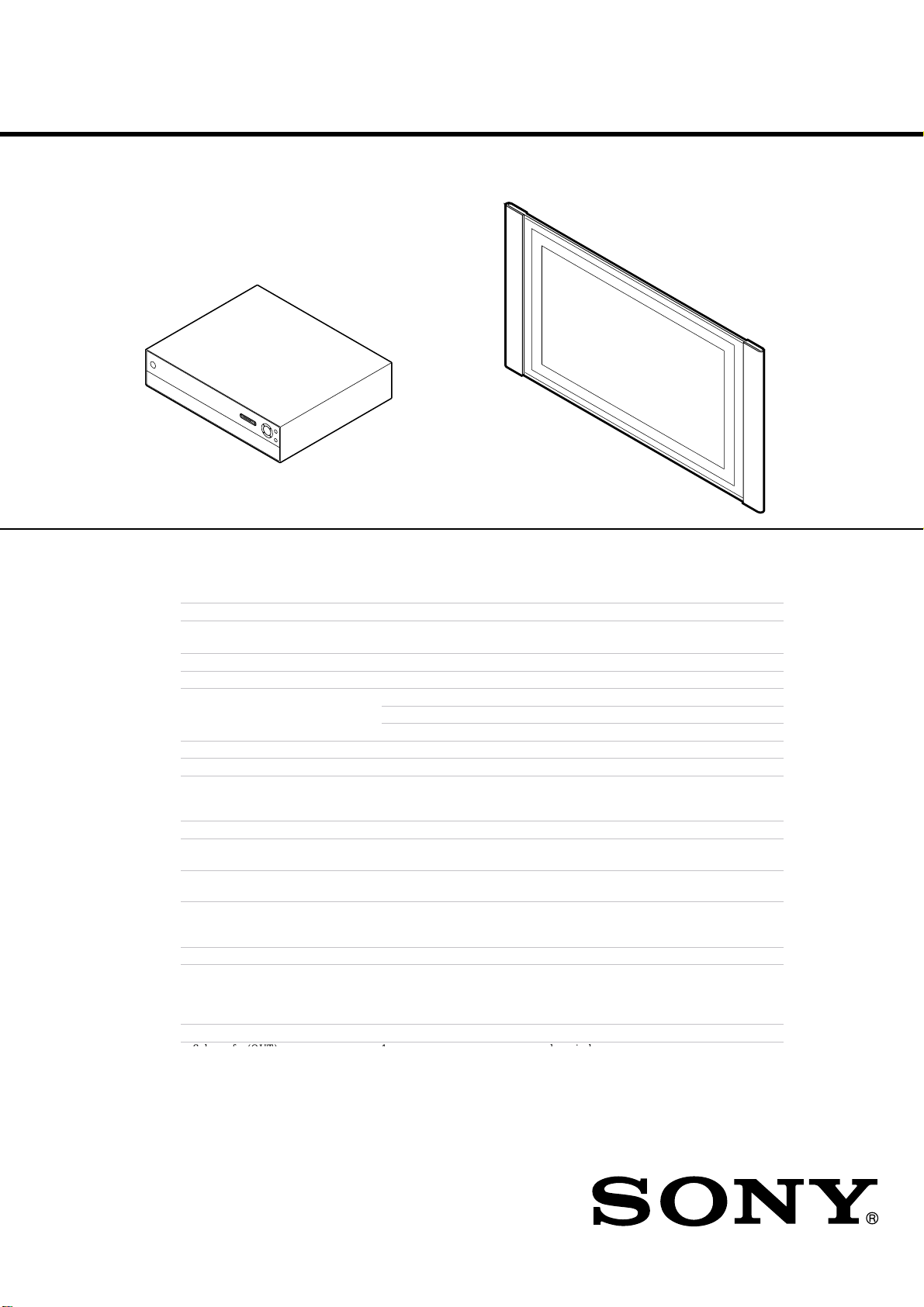
KE-42XBR900
SERVICE MANUAL
SPECIFICATIONS
US Model
Canadian Model
Panel System Plasma Display panel
Display resolution Display resolution:
Antenna 75 ohm external terminal for VHF/UHF
Television System NTSC, American TV Standard
Channel Coverage VHF 2-13
Power Requirements 120V, 60 Hz
Inputs/Outputs
DVI-HDTV 1 terminal, 3.3V T.M.D.S., 50 ohms
Video (IN) 3 total (1 on front panel) 1 Vp-p, 75 ohms unbalanced, sync negative
S Video (IN) (1 on front panel) Y: 1 Vp-p, 75 ohms unbalanced, sync negative
Audio (IN) (1 on front panel) 500 mVrms (100% modulation)
Component Video Input 2 (Y, P
CONTROL S (OUT)
Variable/Fixed Audio (OUT) More than 408 m Vrms at the maximum volume
Monitor/Fixed Audio (OUT) ×1
1024 pixels
UHF 14-69
CATV 1-125
The DVI-HDTV input terminal is compliant with the EIA-861 standard and is not
intended for use with personal computers.
3 total
6 total
1
1
(horizontal) × 768 pixels (vertical)
C: 0.286 Vp-p (Burst signal), 75 ohms
Impedance: 47 kilohm
B
, PR) Y: 1.0 Vp-p, 75 ohms unbalanced, sync negative;
B
: 0.7 Vp-p, 75 ohms
P
P
R
: 0.7 Vp-p, 75 ohms
setting (Variable)
More than 408 mVrms (Fixed)
Impedance (output): 2 kilohms
FLAT PANEL COLOR TV

()
Sub woofer (OUT) 1
RF Input
Converter
Supplied Accessories Remote Control RM-927Y
Screen Size (measured diagonally)
Speaker Output 15W × 2
Dimensions (W × H × D)
Mass Display unit
Power Consumption
2
1
AAA (LR03) Batteries 2 supp
KE-42XBR900 42 inches
PDM-4200 1352 × 720 × 102 mm
MBT-XBR900 430 × 105 × 360 mm
PDM-4200: 39kg (86 lbs )
Media receiver unit
MBT-XBR900: 7.5kg (16 lbs)
In Use
In Standby
phono jack
lied for remote control
AC power code (2)
Display interface cable (1)
Antenna cable (1)
Cleaning cloth
(53 1/4 × 28 3/8 × 4 1/8 in)
(17 × 4 1/4 × 14 1/4 in)
Display unit
Media receiver unit
Under 1.5 W
Design and specifications are subject to change without notice.
PDM-4200: 460 W
MBT-XBR900: 36 W
KE-42XBR900(UC) 2
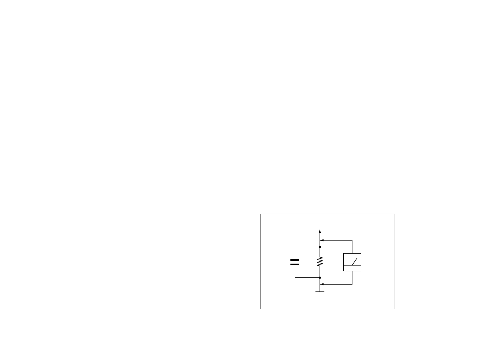
1.5 k
Ω
0.15 µF
AC
Voltmeter
(0.75 V)
To Exposed Metal
Parts on Set
Earth Ground
SAFETY CHECK-OUT
After correcting the original service problem, perform the following safety
checks before releasing the set to the customer:
1. Check the area of your repair for unsoldered or poorly-soldered
connections. Check the entire board surface for solder splashes and
bridges.
2. Check the interboard wiring to ensure that no wires are “pinched” or
contact high-wattage resistors.
3. Check that all control knobs, shields, covers, ground straps, and
mounting hardware have been replaced. Be absolutely certain that you
have replaced all the insulators.
4. Look for unauthorized replacement parts, particularly transistors, that
were installed during a previous repair. Point them out to the customer
and recommend their replacement.
5. Look for parts which, though functioning, show obvious signs of
deterioration. Point them out to the customer and recommend their
replacement.
6. Check the line cords for cracks and abrasion. Recommend the
replacement of any such line cord to the customer.
7. Check the connector shell, metal trim, “metallized” knobs, screws, and
all other exposed metal parts for AC Leakage. Check leakage as described right.
LEAKAGE TEST
The AC leakage from any exposed metal part to earth ground and from all
exposed metal parts to any exposed metal part having a return to chassis,
must not exceed 0.5 mA (500 microamperes).
Leakage current can be measured by any one of three methods.
1. A commercial leakage tester, such as the Simpson 229 or RCA WT540A. Follow the manufacturers’ instructions to use these instruments.
2. A battery-operated AC milliammeter. The Data Precision 245 digital
multimeter is suitable for this job.
3. Measuring the voltage drop across a resistor by means of a VOM or
battery-operated AC voltmeter. The “limit” indication is 0.75 V, so
analog meters must have an accurate low-voltage scale. The Simpson 250
and Sanwa SH-63Trd are examples of a passive VOMs that are suitable.
Nearly all battery operated digital multimeters that have a 2 V AC range
are suitable. (See Fig. A)
Fig. A. Using an AC voltmeter to check AC leakage.
KE-42XBR900(UC) 3

WARNING!!
AVERTISSEMENT!!
SAFETY-RELATED COMPONENT WARNING!!
COMPONENTS IDENTIFIED BY SHADING AND MARK ! ON THE
SCHEMATIC DIAGRAMS, EXPLODED VIEWS AND IN THE
PARTS LIST ARE CRITICAL FOR SAFE OPERATION. REPLACE
THESE COMPONENTS WITH SONY PARTS WHOSE PART
NUMBERS APPEAR AS SHOWN IN THIS MANUAL OR IN
SUPPLEMENTS PUBLISHED BY SONY. CIRCUIT ADJUSTMENTS THAT ARE CRITICAL FOR SAFE OPERATION ARE
IDENTIFIED IN THIS MANUAL. FOLLOW THESE PROCEDURES
WHENEVER CRITICAL COMPONENTS ARE REPLACED OR IMPROPER OPERATION IS SUSPECTED.
ATTENTION AUX COMPOSANTS RELATIFS À LA SÉCURITÉ!!
LES COMPOSANTS IDENTIFIÉS PAR UNE TRAME ET UNE
MARQUE ! SONT CRITIQUES POUR LA SÉCURITÉ. NE LES
REMPLACER QUE PAR UNE PIÈCE PORTANT LE NUMÉRO
SPECIFIÉ. LES RÉGLAGES DE CIRCUIT DONT L’IMPORTANCE EST
CRITIQUE POUR LA SÉCURITÉ DU FONCTIONNEMENT SONT
IDENTIFIÉS DANS LE PRÉSENT MANUEL. SUIVRE CES
PROCÉDURES LORS DE CHAQUE REMPLACEMENT DE
COMPOSANTS CRITIQUES, OU LORSQU’UN MAUVAIS
FONCTIONNEMENT EST SUSPECTÉ.
KE-42XBR900(UC) 4
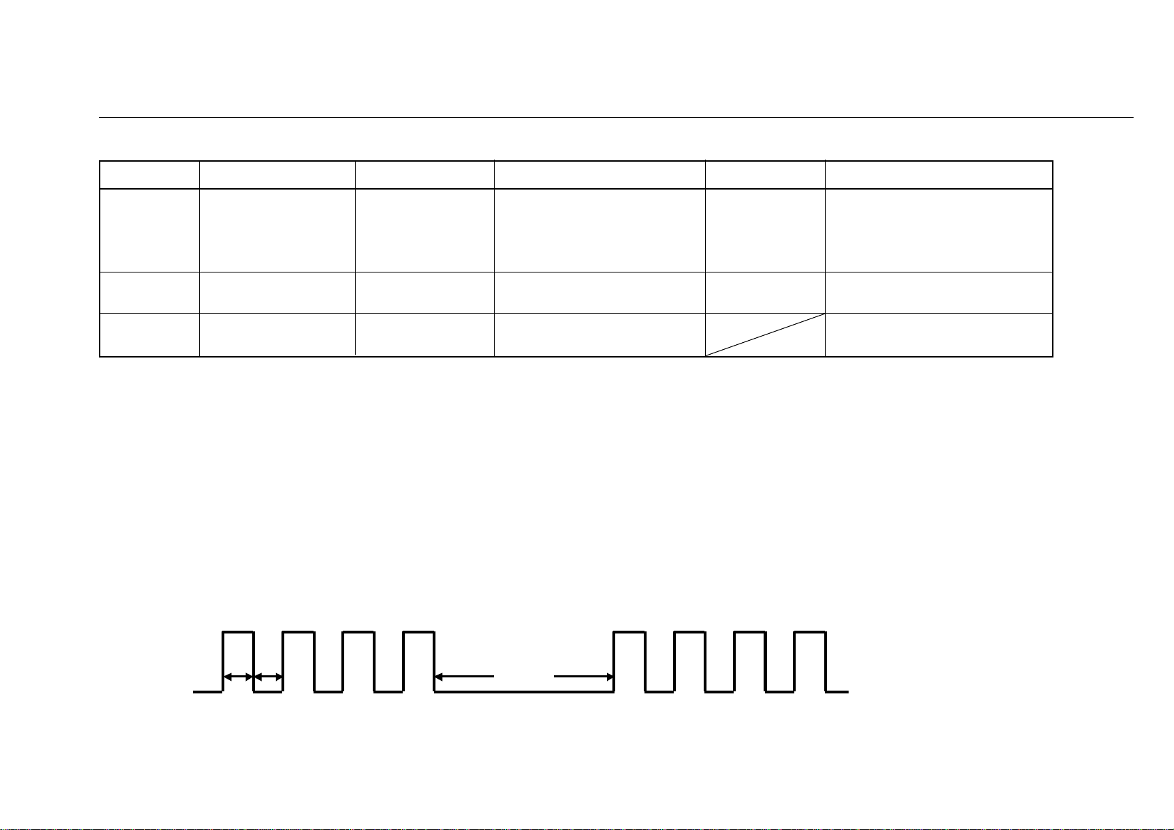
DIAGNOSIS (Reliability Self Diagnostic Display Specifications for MEDIA RECEIVER)
The abnormal conditions are indicated by the following LED flashes.
Flash Count Error Display Name Error Description Oprating Detection Port
4 Fan Error Error detected for Detects Low when fan IC6200 pin #2
fan box function normally.
Detects High when Fan stops
abnormally
8 Digtal OVP OVP for DD Con- Detects High when normal. IC5210 pin #49
verter on DP board Detects Low when abnormal.
9 Panel Error Panel malfunction Detects during communication
detected with panel.
1) *Operation count is based on WDT.
*For flashes, the Power/Standby LED flashes in red.
*The flash period is based on the reliability standard.
*A failure part can be expected by the number of times of blink of LED.
*When two failures occur, the failure item generated previously is detected.
*When failure occurs simultaneously, an item with little number of times of blink is detected.
*In other than “Fan Error”, the unit is in standby state and blink LED at intervals of regulation.
In “Fan Error”, the unit is in a standby state after display for 1 minute about the message of “Fan problem –
Powering down”
Repair part
• FAN
• FAN CONNECTOR
• SET 11V LINE
• SET 5V LINE
DP board
• Q1612, Q1613, Q1614
Panel Display Unit
• Timing of LED blink (example of 4 times blink)
ON
OFF
every about 0.3s
about 3s
KE-42XBR900(UC) 5

In the following case, POWER LED of Media Receiver Box blinks at a fixed interval in ORAN GE
2)
• When the cable which connects between Media Receiver Box and Panel Display has fallen out.
• When the AC code for Panel Display has fallen out.
In the following case, POWER LED of Panel Display
blinks at a fixed interval in ORANGE
• When the cable which connects between Media Receiver Box and Panel Display has fallen out.
• When the AC code for Media Receiver Box has fallen out.
The example which judges whether it is failure
3)
• POWER LED of Media Receiver Box: Blink 9 times in RED, and of Panel Display blink,
and No picture or Power circuit does not work → Large possibility that Panel Display is out of order.
• When turn on Media Receiver Box, and NO LED of Box shine
→ Large possibility that Media Receiver Box is out of order.
When NO Blue LED of Box shine → Large possibility that Media Receiver Box is out of order.
•
Check SET5V or IIC line on H1 board.
• When turn on Media Receiver Box, and Fan does not work
→ Large possibility that Media Receiver Box is out of order
KE-42XBR900(UC) 6

TABLE OF CONTENTS
Section Title Page Section Title Page
SAFETY CHECK-OUT ................................................... 3
DIAGNOSIS ...................................................................... 5
1. DISASSEMBLY
1-1. Display Unit (PDM-4200)
1-1-1.Rear Cover Removal ....................................... 1-1
1-1-2.K and F Boards Removal ................................ 1-2
1-1-3.P Board Removal ............................................ 1-3
1-1-4.G and F2 Boards Removal .............................. 1-4
1-1-5.R1 Board Removal .......................................... 1-5
1-1-6.R2 Board Removal .......................................... 1-6
1-2. Media Receiver Unit (MBT-XBR900)
1-2-1.Panel and Covers Removal.............................. 1-7
1-2-2.H1 Board Removal ......................................... 1-8
1-2-3.H4 Board Removal.......................................... 1-9
1-2-4.H3 Board Removal ......................................... 1-10
1-2-5.MS2 Board Removal....................................... 1-11
1-2-6.H2 Board Removal ......................................... 1-12
1-2-7.A Board Removal............................................ 1-13
1-2-8.B Block Assy Removal .................................. 1-14
1-2-9.M, AD, and AU Boards Removal ................... 1-15
1-2-10.A and AU Boards Removal........................... 1-16
1-2-11.M Board Removal ........................................ 1-17
1-2-12.IF Boards Removal........................................ 1-18
1-2-13.U1 Boards Removal ...................................... 1-19
1-2-14.U2 Boards Removal ...................................... 1-20
2. ADJUSTMENTS
2-1. VS, VD Voltage Adjustment (PDM-4200)............... 2-1
2-2. White Balance Adjustment (PDM-4200).................. 2-2
3. TROUBLESHOOTING
3-1. Display Unit (PDM-4200) ........................................ 3-1
3-2. Media Receiver Unit (MBT-XBR900) ..................... 3-2
4. DIAGRAMS
4-1. Block Diagrams
4-1-1.Display Unit(PDM-4200)................................ 4-1
4-1-2.Media Receiver Unit (MBT-XBR900) ........... 4-6
4-2. Frame Diagram ......................................................... 4-15
4-3. Circuit Boards Location
4-3-1.Display Unit(PDM-4200)................................ 4-16
KE-42XBR900(UC) 7

Section Title Page Section Title Page
4-3-2.Media Receiver Unit (MBT-XBR900)............ 4-17
4-4. Schematic Diagrams and Printed WiringBoards....... 4-18
4-4-1.Display Unit(PDM-4200)................................ 4-19
(1)Schematic Diagrams of F Board ......................... 4-19
(2)Schematic Diagram of F2 Board ......................... 4-20
(3)Schematic Diagrams of G Board ......................... 4-21
(4)Schematic Diagram of K Board .......................... 4-25
(5)Schematic Diagrams of P Board ......................... 4-27
(6)Schematic Diagrams of R1 amd R2 Boards ........ 4-32
4-4-2.Media Receiver Unit (MBT-XBR900)................... 4-33
(1)Schematic Diagrams of A Board ......................... 4-33
(2)Schematic Diagram of AD Board ....................... 4-36
(3)Schematic Diagrams of AU Board ...................... 4-41
(4)Schematic Diagram of DP Board ........................ 4-43
(5)Schematic Diagrams of H1 and H5 Boards ......... 4-45
(6)Schematic Diagrams of H2 Board ....................... 4-47
(12)Schematic Diagram of U2 Board ...................... 4-61
(13)Schematic Diagram of BM1C Board ................ 4-62
(14)Schematic Diagram of DICA Board ................. 4-65
4-5. Semiconductors......................................................... 4-71
5. EXPLODED VIEWS .................................................. 5-1
5-1. Display Unit (PDM-4200) ....................................... 5-2
5-2. Media Receiver Unit-1 (MBT-XBR900) ................. 5-4
5-3. Media Receiver Unit-2 (MBT-XBR900).................. 5-6
Packing Materials for Display Unit (PDM-4200)
5-4.
........ 5-7
5-5. Packing Materials for Media Receiver Unit
(MBT-XBR900) ...................................................... 5-8
6. ELECTRICAL PARTS LIST ................................... 6-1
(7)Schematic Diagram of H3 and H4 Board ............ 4-48
(8)Schematic Diagrams of IFA Board ..................... 4-49
(9)Schematic Diagrams of M Board ........................ 4-51
(10)Schematic Diagrams of MS2 Boards ................ 4-57
(11)Schematic Diagrams of U1 Board ..................... 4-59
KE-42XBR900(UC) 8
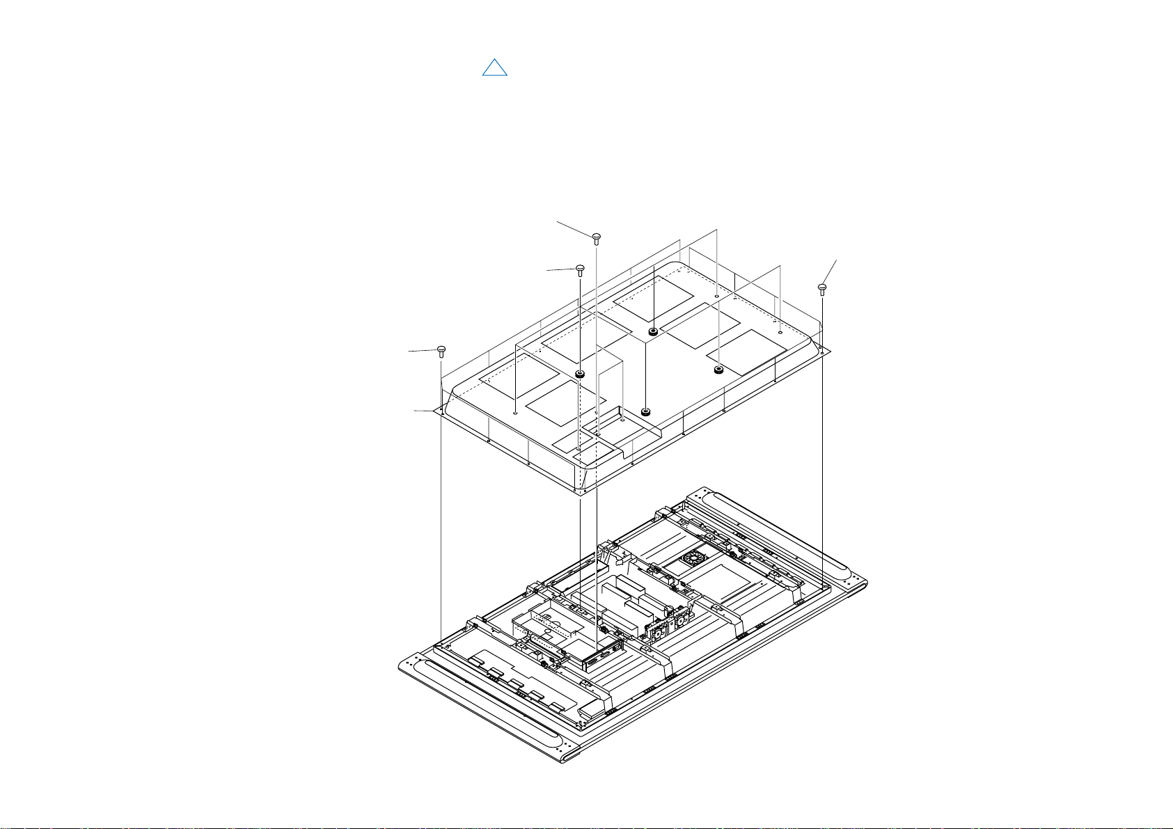
1-1. PANEL UNIT (PDM-4200)
1-1-1. REAR COVER REMOVAL
1
SECTION 1
DISASSEMBLY
2 Three screws
(+PSW 3X8)
3 Ten screws
(+BVTP 4X16)
4 Rear cover assy
1 Eight screws
(+PSW 5X16)
3 Ten screws
(+BVTP 4X16)
KE-42XBR900(UC) 1-1
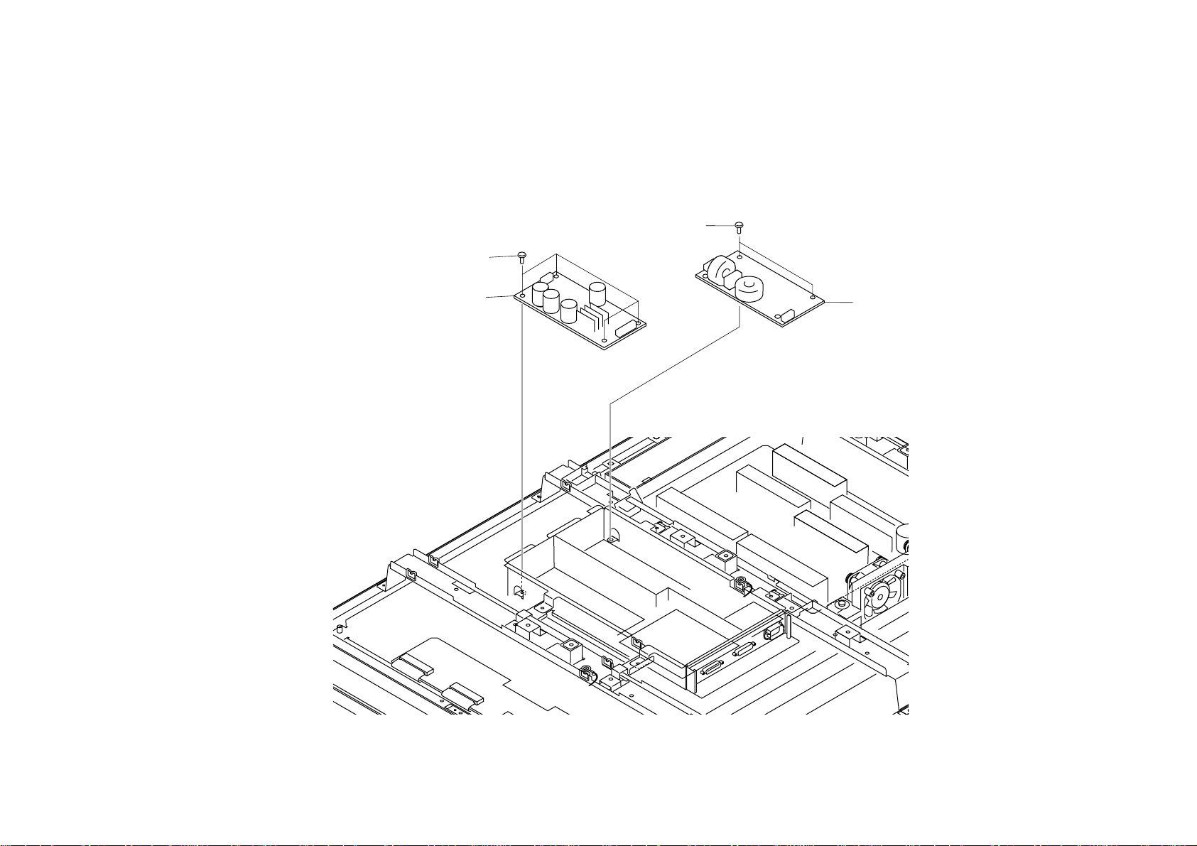
1-1-2. K AND F BOARDS REMOVAL
1 Two screws
(+PSW 3X8)
3 Four screws
(+PSW 3X8)
4 K Board
2 F Board
KE-42XBR900(UC) 1-2
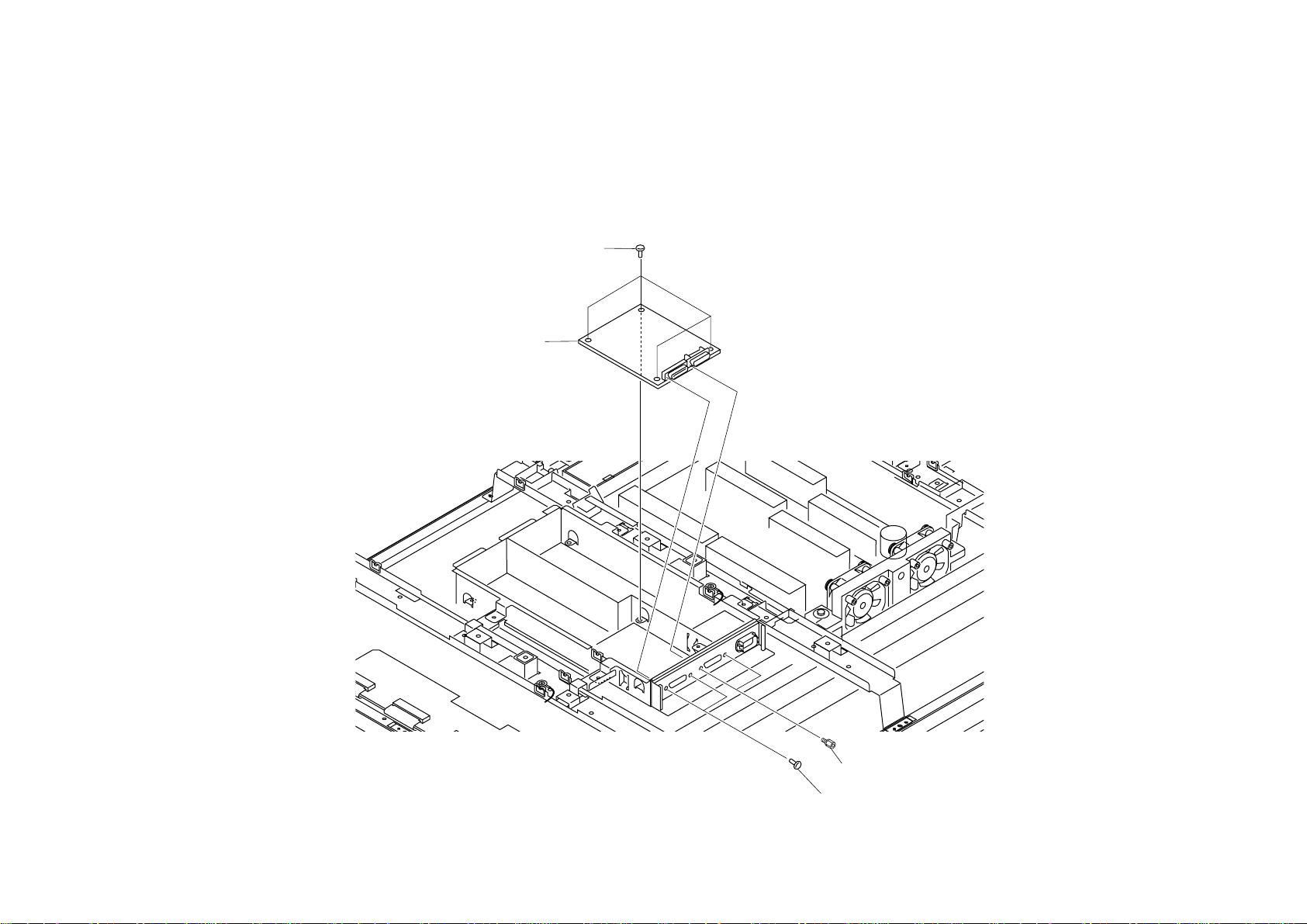
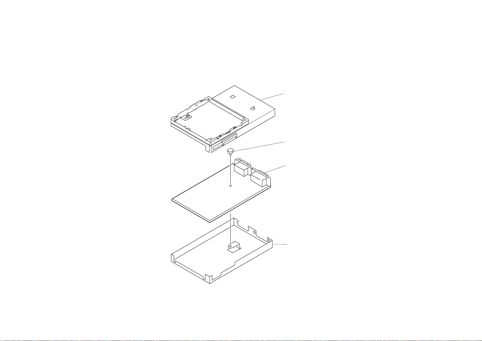
1-1-3. P BOARD REMOVAL
3 Four screws
(+PSW 3X8)
4 P Board
1 Two Connector screws
2 Two screws
(M2.6 S HEAD)
KE-42XBR900(UC) 1-3
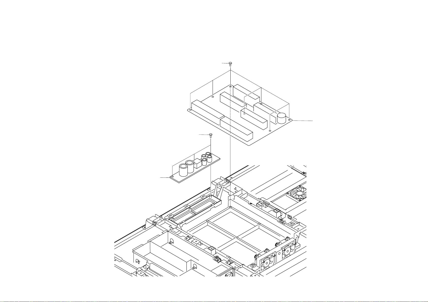
1-1-4. G AND F2 BOARDS REMOVAL
1 Three screws
(+BVTP 3X12)
2 F2 Board
3 Seven screws
(+BVTP 3X12)
4 G Board
KE-42XBR900(UC) 1-4
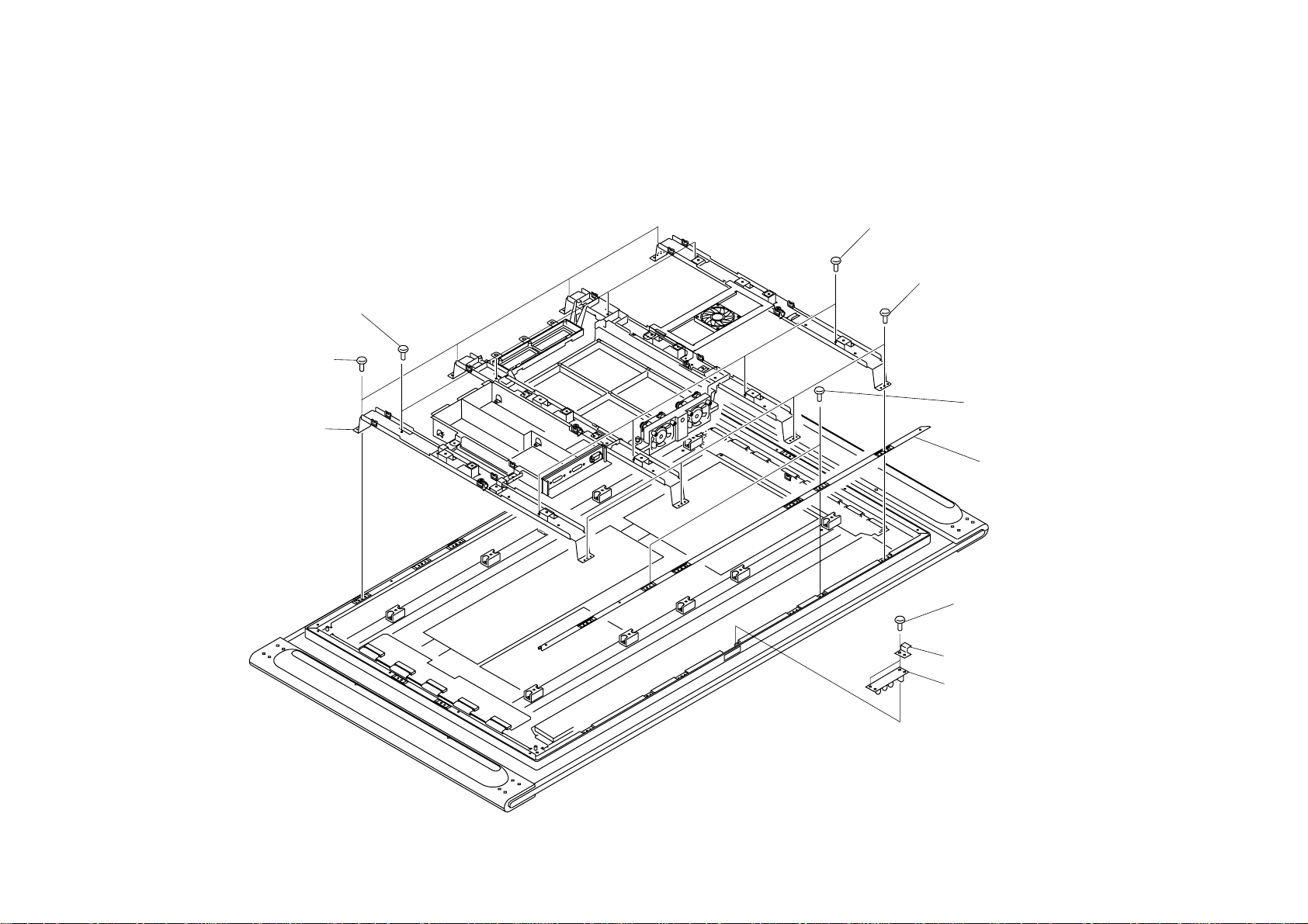
1-1-5. R1 BOARD REMOVAL
2 Filter bracket (V) assy
1 Two screws
(+BVTP 4X16)
3 Three screws
(+BVTP 3X10)
4 R1 Board
Earth plate
KE-42XBR900(UC) 1-5
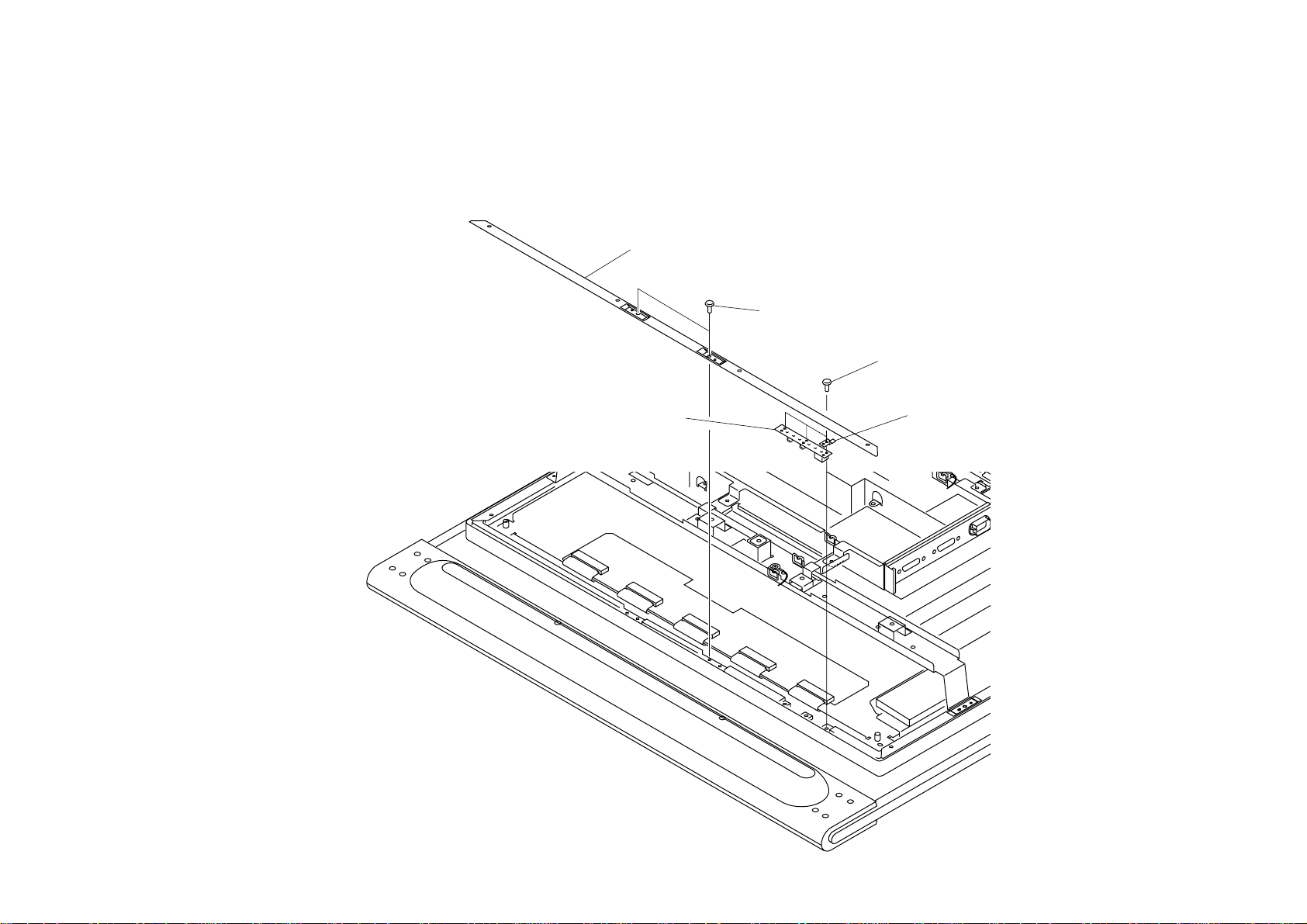
1-1-6. R2 BOARD REMOVAL
2 Four screws
(+PSW 5X16)
1 Four screws
(+BVTP 4X16)
3 Panel assy
2 Four screws
(+PSW 5X16)
1 Four screws
(+BVTP 4X16)
4 Two screws
(+BVTP 4X16)
5 Filter bracket (H) assy
6 Two screws
(+BVTP 3X10)
Earth plate
7 R2 Board
KE-42XBR900(UC) 1-6
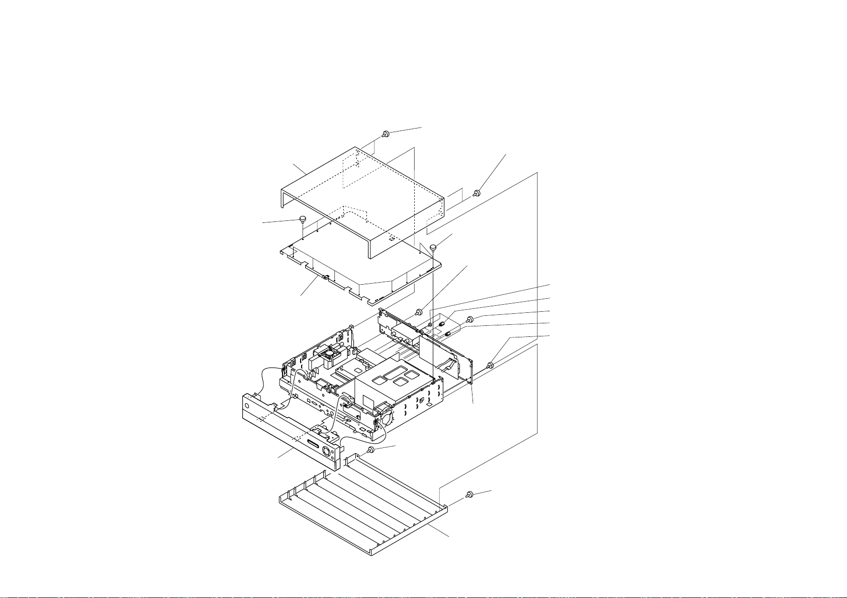
1-2. MEDIA RECEIVER UNIT (MBT-XBR900)
1-2-1. PANEL AND COVERS REMOVAL
5 Top cover assy
1 Two screws
(+PSW 3X8)
3 Two screws
(+PSW 3X8)
7 Four screws
(precision)
8 Top chassis assy
9 Front panel assy
7 Eight screws
(precision)
3 Two screws
(+PSW 3X8)
0 Two screws GRIP, M2.6 S'HEAD(EG)
!¡ Two screws (HEX)
!£ Four screws (+PSW 3X8)
!™ Two screws (HEX)
!¢ Two screws (+PSW 3X8)
!∞ Rear panel
2 Screw
(+PSW 3X8)
4 Screw
(+PSW 3X8)
6 Bottom cover assy
KE-42XBR900(UC) 1-7
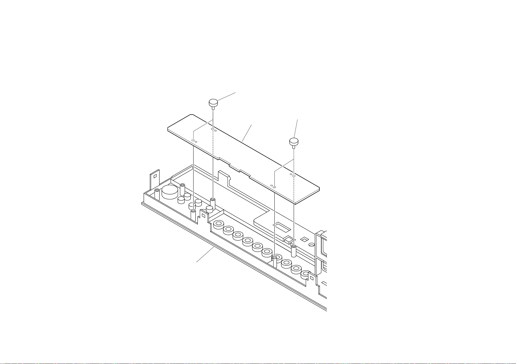
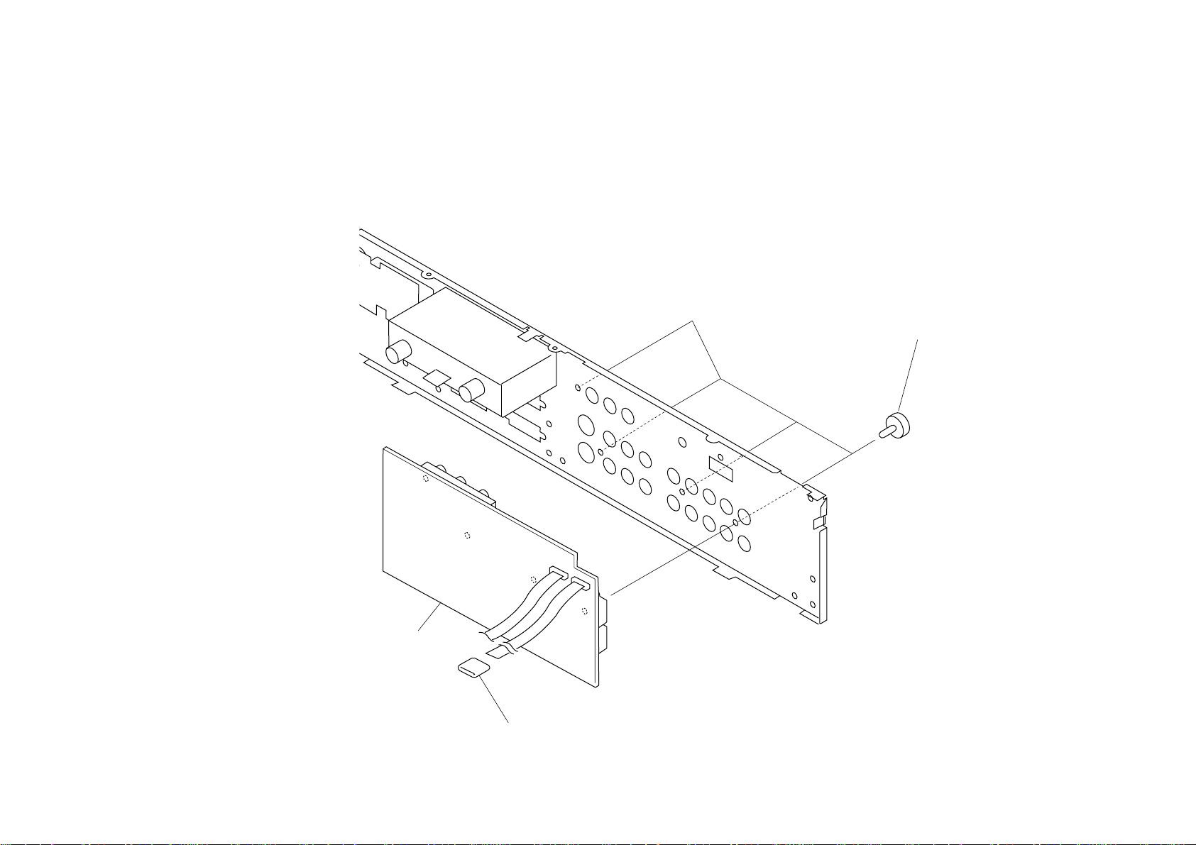
1-2-2. H1 BOARD REMOVAL
1 Two screws
(+BVTP 3X12)
Front panel
2 H1 Board
1 Two screws
(+BVTP 3X12)
KE-42XBR900(UC) 1-8
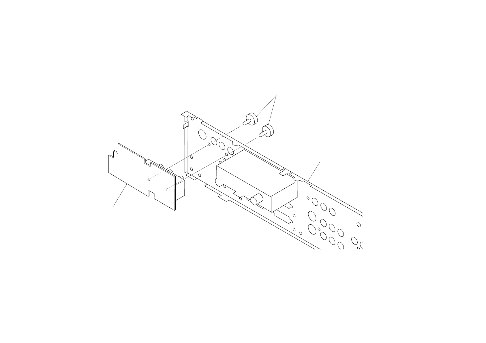
1-2-3. H4 BOARD REMOVAL
1 Two screws
(+BVTP 3X12)
2 H4 Board
Front panel
KE-42XBR900(UC) 1-9
1-2-4. H3 BOARD REMOVAL
1 Three screws
(+BVTP 3X12)
2 H3 Board
Front panel
KE-42XBR900(UC) 1-10
1-2-5. MS2 BOARD REMOVAL
1 Two screws
(+BVTP 3X12)
4 MS2 Board
3 Two screws
(+BVTP 3X12)
2 MS bracket
Front panel
KE-42XBR900(UC) 1-11
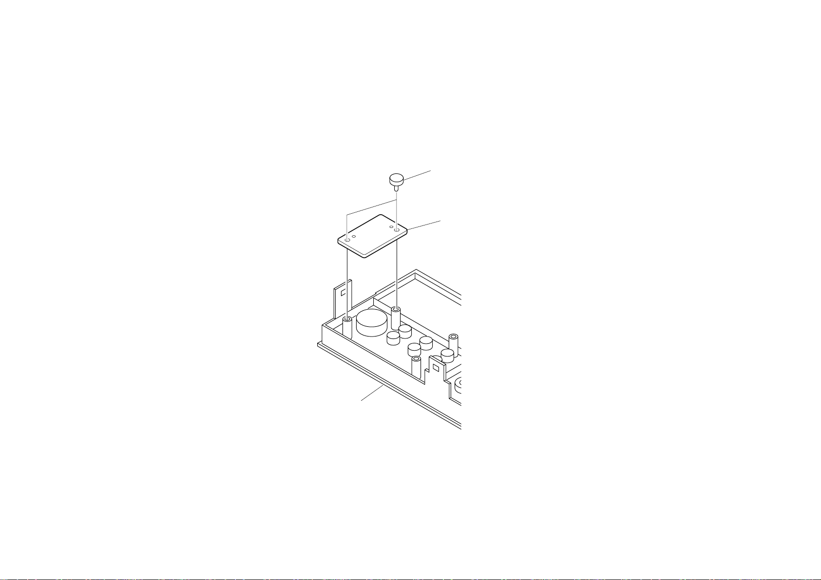
1-2-6. H2 BOARD REMOVAL
1 Two screws
(M 3X8),P,SW (+)
2 H2 Board
KE-42XBR900(UC) 1-12
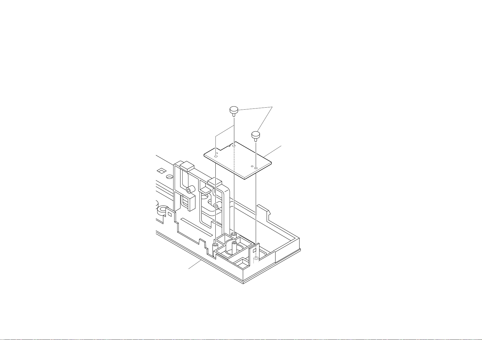
1-2-7. A BOARD REMOVAL
1 Two screws
(M 3X8),P,SW (+)
2 A Board
1 Two screws
(M 3X8),P,SW (+)
1 Screw
(M 3X8),P,SW (+)
KE-42XBR900(UC) 1-13
1-2-8. B BLOCK ASSY REMOVAL
1 B Block assy
KE-42XBR900(UC) 1-14
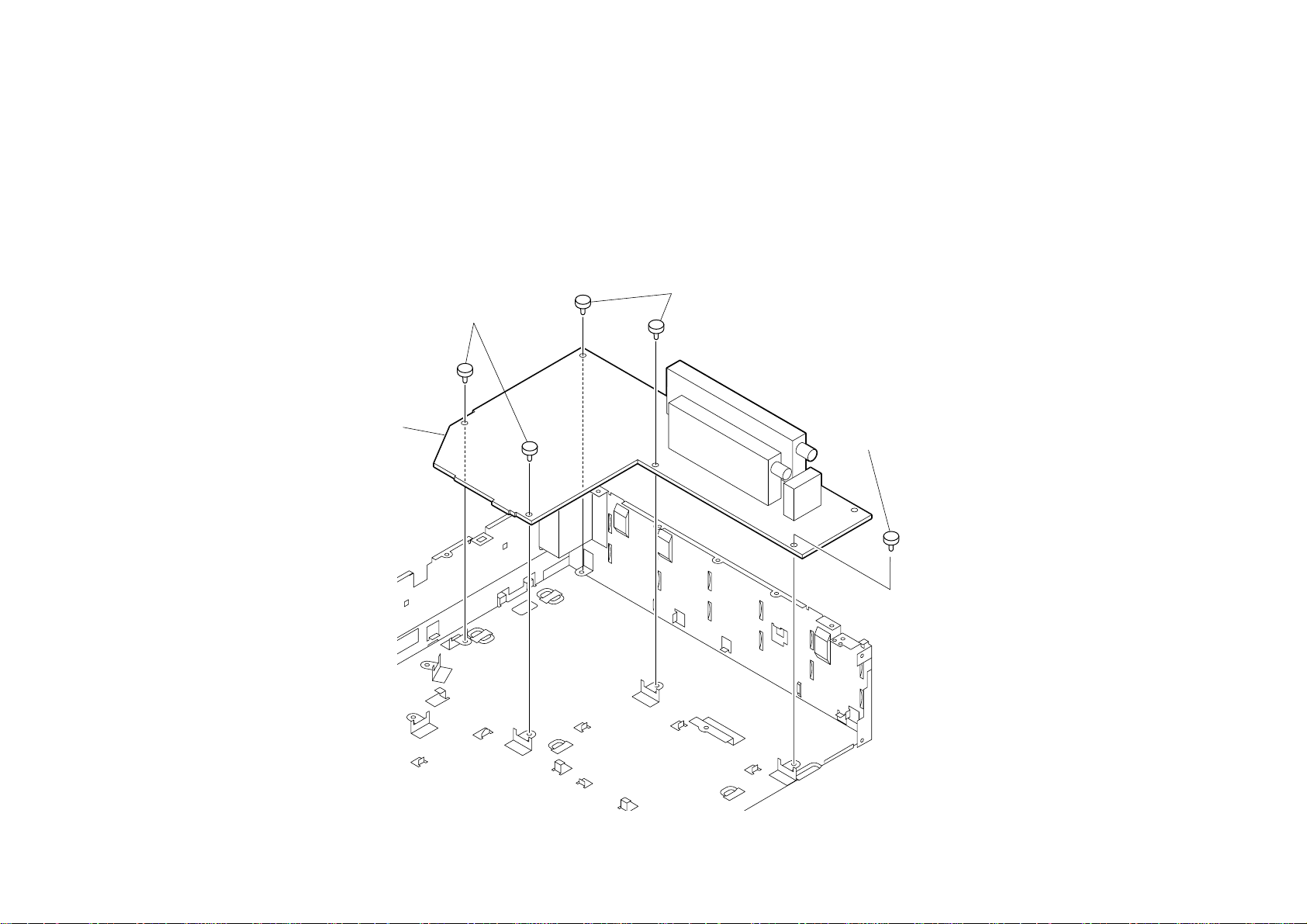
1-2-9. M, AD, AND AU BOARDS REMOVAL
1 Screw
(+PSW 3x8)
2 Shield case
KE-42XBR900(UC) 1-15
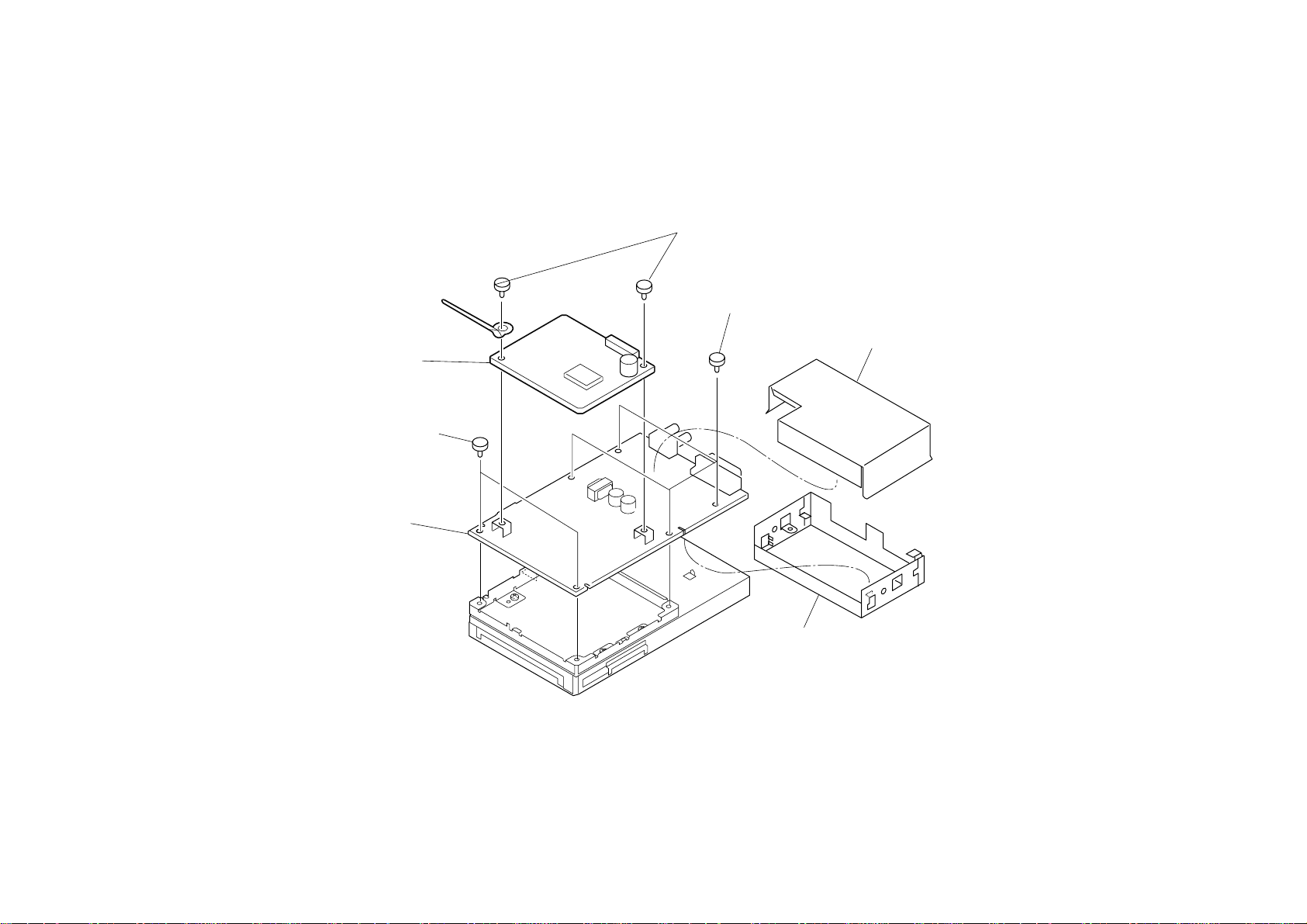
1-2-10.AD AND AU BOARDS REMOVAL
2 AU Board
3 Two screws
(PSW 3x8)
3 AD Board
1 Two screws
(PSW 3x8)
3 Four screws
(PSW 3x8)
Shield upper
Shield main
KE-42XBR900(UC) 1-16
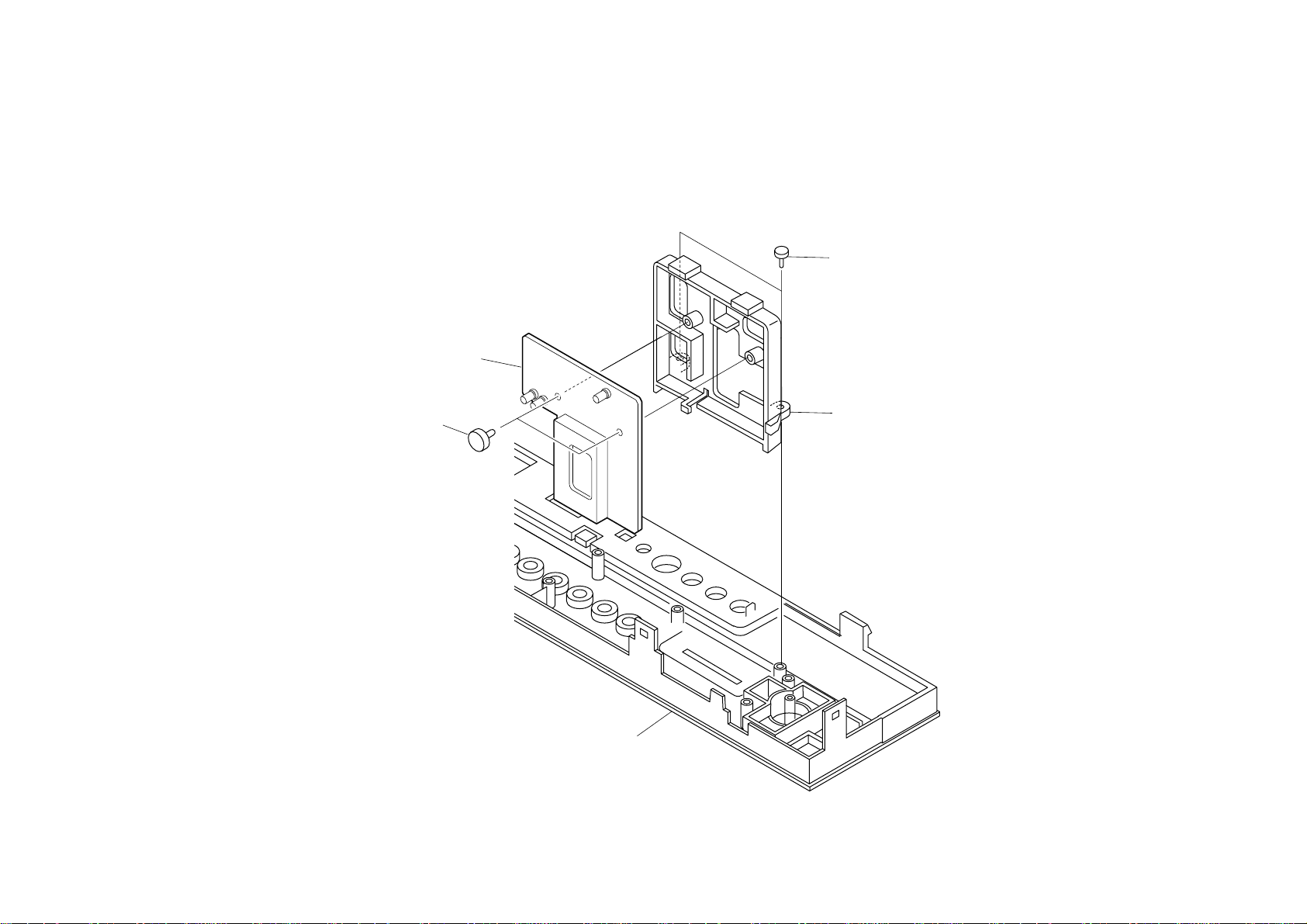
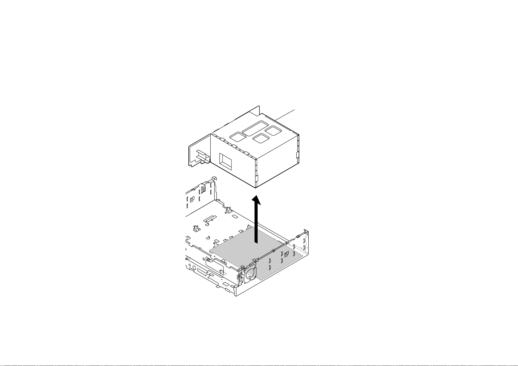
1-2-11.M BOARD REMOVAL
1 Shield case (upper)
2 Screw
(+PSW 3x8)
3 M Board
Shield case (main)
KE-42XBR900(UC) 1-17
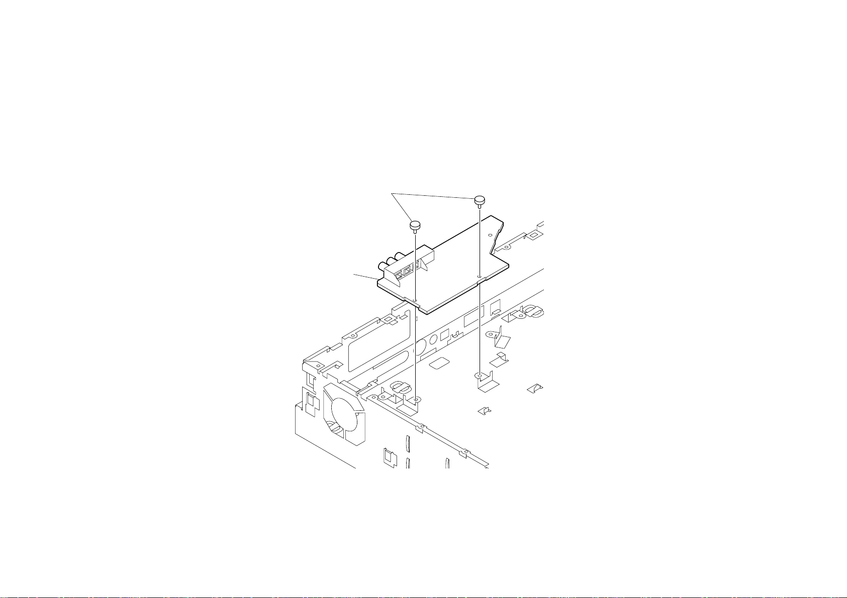
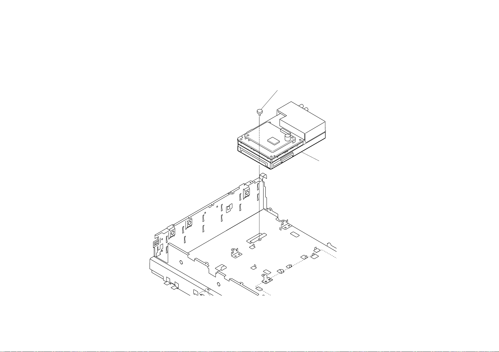
1-2-12.IF BOARD REMOVAL
2 Screw
(+PSW 3x8)
1 IF Shield sheet
3 IF Board
B Block assy
KE-42XBR900(UC) 1-18
1-2-13.U1 BOARD REMOVAL
1 Four screws
(+BVTP 3x12)
2 U1 Board
3 Core (FPC)
KE-42XBR900(UC) 1-19
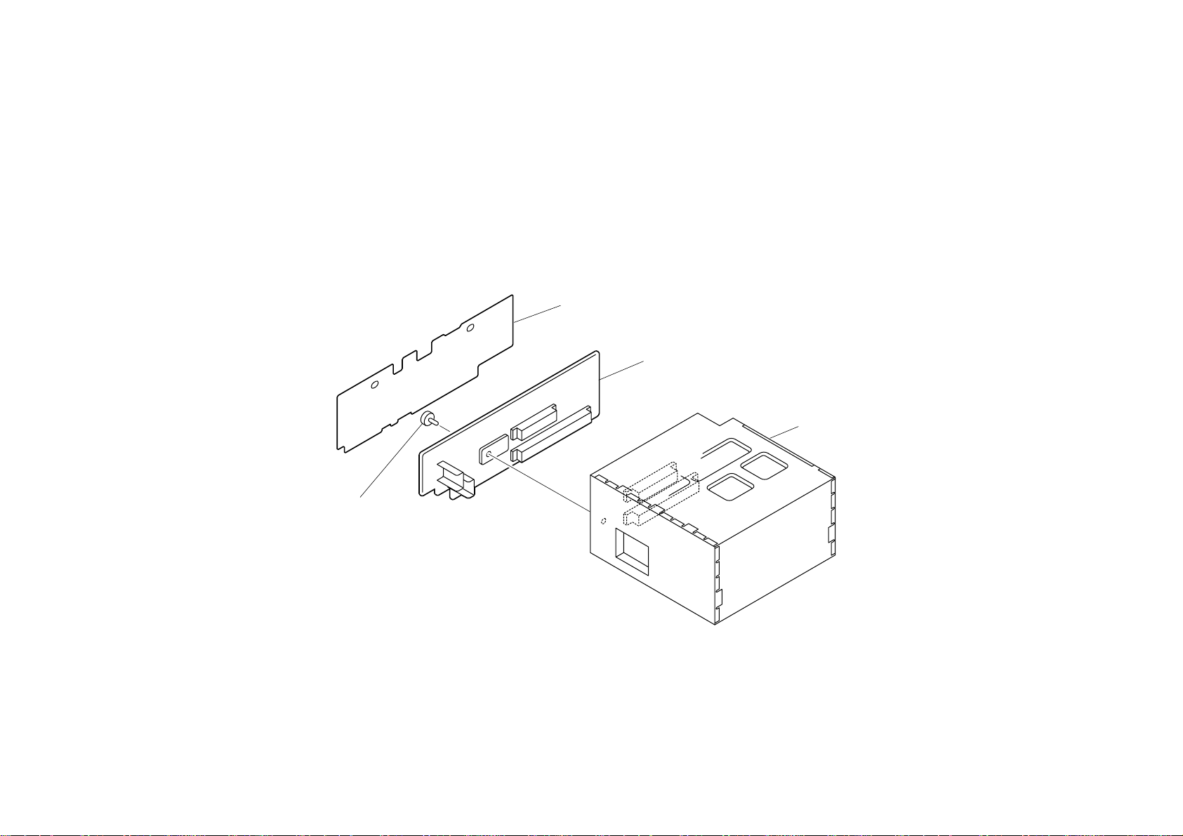
1-2-14.U2 BOARD REMOVAL
2 U2 Board
1 Tow screws
(+BVTP 3x12)
Rear panel
KE-42XBR900(UC) 1-20
1
SECTION 2
ADJUSTMENTS
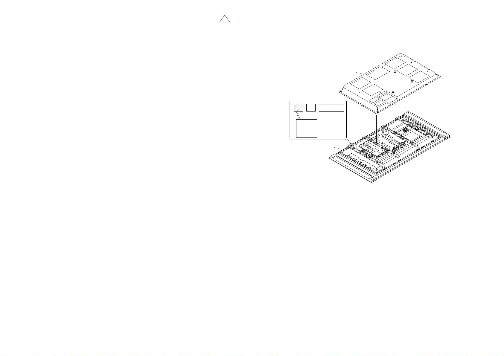
2-1. VS, VD Voltage Adjustment (PDM-4200)
• Preparation for adjustment
1.Slide the DIP switch (S3201) No. 8 of P board to on position with no silkscreen mark r.
2.Connect a digital voltmeter to the following terminals of G board.
VS voltage=G board TP1701 (VS)-TP1502 (GND)
VD voltage=G board TP1501 (VD)-TP1502 (GND)
3.Connect a AC cord in DISPLAY UNIT.
4.Perform the adjustment in 10 seconds after connecting the cord.
• Procedure for adjustment
1. Slide the DIP switch (S3201) No. 7 of P board to on position with no silkscreen mark r.
2. Confirm the lighting of SONY LOGO LED.
3. Adjust the VS voltage to the following voltage value.
VS voltage of proper value for each model.
Ex.) VS proper value=185V thru 185.6V at 185V.
(Check the proper value with a seal on upper left of panel unit. Refer to right Fig.)
4. Adjust the VD voltage to the following voltage value.
VD voltage ±0.3V of proper value for each model.
Ex.) VD proper value=64.7V thru 65.3V at 65.0V.
(Check the proper value with a seal on upper left of panel unit. Refer to right Fig.)
5. Check a Fan rotation.
6. Slide the DIP Switch (S3201) No. 7 of P board to the off position with the silkscreen mark
r.
7. Slide the DIP Switch (S3201) No. 8 of P board to the off position with the silkscreen mark
r.
8. Disconnect an AC cord of DISPLAY UNIT.
9. Reconnect the AC cord in one second.
10. Assure that “POWER ON/STANDBY” LEDs is flashing amber.
+6V
–0V
<SEAL POSITION>
SERIAL No.
301201440
Vd=65V
Vs=193.4V
CODE AA-01
Rear cover assy
BAR CODE SEAL
Panel unit
KE-42XBR900(UC) 2-1
 Loading...