

Sony KE 42XBR900 User Manual
Flat Panel Color TV KE-42XBR900/KE-50XBR900
4-092-940-15 (1)
Flat Panel Color TV
Operating Instructions
KE-42XBR900
KE-50XBR900
2002 Sony Corporation

WARNING
To reduce the risk of fire or shock hazard, do not expose the TV to rain or
moisture.
CAUTION
RISK OF ELECTRIC SHOCK
DO NOT OPEN
ATTENTION
RISQUE DE CHOC ELECTRIQUE,
NE PAS OUVRIR
PRECAUCION
RIESGO DE CHOQUE ELECTRICO
NO ABRIR
CAUTION: TO REDUCE THE RISK OF ELECTRIC SHOCK,
DO NOT REMOVE COVER (OR BACK).
NO USER-SERVICEABLE PARTS INSIDE.
REFER SERVICING TO QUALIFIED SERVICE PERSONNEL.
This symbol is intended to alert the user to the presence
of uninsulated “dangerous voltage” within the
product’s enclosure that may be of sufficient
magnitude to constitute a risk of electric shock to
persons.
This symbol is intended to alert the user to the presence
of important operating and maintenance (servicing)
instructions in the literature accompanying the
appliance.
Note on Caption Vision
This television receiver provides display of television closed captioning in
accordance with §15.119 of the FCC rules.
Note to CATV System Installer
This reminder is provided to call the CATV system installer’s attention to
Article 820-40 of the National Electrical Code (NEC) that provides
guidelines for proper grounding and, in particular, specifies that the cable
ground shall be connected to the grounding system of the building, as close
to the point of cable entry as practical.
Use of this television receiver for other than private viewing of programs
broadcast on UHF or VHF or transmitted by cable companies for the use
of the general public may require authorization from the broadcaster/cable
company and/or program owner.
NOTIFICATION
This equipment has been tested and found to comply with the limits for a
Class B digital device pursuant to Part 15 of the FCC Rules. Thes e limits
are designed to provide reasonable protection against harmful interference
in a residential installation. This equipment generates, uses, and can radiate
radio frequency energy and, if not installed and used in accordance with the
instructions, may cause harmful interference with radio communications.
However, there is no guarantee that interference will not occur in a
particular installation. If this equipment does cause harmful interference to
radio or television reception, which can be determined by turning the
equipment off and on, the user is encouraged to try to correct the
interference by one or more of the following measures:
s Reorient or relocate the receiving antennas.
s Increase the separation between the equipment and receiver.
s Connect the equipment into an outlet on a circuit different from that
to which the receiver is connected.
s Consult the dealer or an experienced radio/TV technician for help.
You are cautioned that any changes or modifications not expressly
approved in this manual could void your authority to operate this
equipment.
CAUTION
To prevent electric shock, do not use this polarized AC plug with an
extension cord, receptacle or other outlet unless the blades can be fully
inserted to prevent blade exposure.
CAUTION
When using TV games, computers, and similar products with your TV,
or viewing a TV station whose logo always stays on the screen, keep
the brightness and contrast functions at low settings. If a fixed
(non-moving) pattern such as a station logo is left on the screen for
long periods of time, especially at a high brightness or contrast setting,
the image can be permanently imprinted onto the screen. These types
of imprints are not covered by your warranty.
Safety
s Operate the TV only on 120 V AC.
s The plug is designed, for safety purposes, to fit into the wall outlet
only one way. If you are unable to insert the plug fully into the outlet,
contact your dealer.
s If any liquid or solid object should fall inside the cabinet, unplug the
TV immediately and have it checked by qualified service personnel
before operating it further.
s If you will not be using the TV for several days, disconnect the
power by pulling the plug itself. Never pull on the cord.
s For details concerning safety precautions, see “Important
Safeguards” on page 3.
Important Notice
s When used at an altitude of greater than 2400m or 7872feet (air
pressure less than 750hPa), this Plasma Display Panel may generate
a low buzzing sound as a result of the difference between the interior
and exterior air pressure of the panels. This is not considered a defect
and is not covered under by the Limited Warranty.
1
Installing
s To prevent internal heat buildup, do not block the ventilation
openings.
s Do not install the TV in a hot or humid place, or in a place subject to
excessive dust or mechanical vibration.
s Avoid operating the TV at temperatures below 5°C (41°F).
s If the TV is transported directly from a cold to a warm location, or if
the room temperature changes suddenly, the picture may be blurred
or show poor color due to moisture condensation. In this case, please
wait a few hours to let the moisture evaporate before turning on the
TV.
s To obtain the best picture, do not expose the screen to direct
illumination or direct sunlight. It is recommended to use spot
lighting directed down from the ceiling or to cover the windows that
face the screen with opaque drapery. It is desirable to install the TV
in a room where the floor and walls are not of a reflective material.
CAUTION
The following SONY appliance(s) for use only with the following TV
STAND or WALL-HANGING RACK UNIT. Use with other TV STAND
or WALL-HANGING RACK UNIT is capable of resulting in instability
causing possible injury.
SONY APPLIANCE MODEL NO.
KE-42XBR900 (PDM-4200)
KE-50XBR900 (PDM-5000)
TABLE TOP STAND MODEL NO.
SU-P42T1 (for PDM-4200)
SU-P50T1 (for PDM-5000)
RYOJU KAKO CO., LTD
CAUTION
How to reduce the risk of “Image Retention” on your TV
Bright, stationary images such as TV station logos displayed on your
TV can cause permanent damage to your TV, resulting in retention of
the image in the picture. Please take the following steps to reduce the
risk of causing image retention:
View a variety of program sources or programming material.
Image retention can occur when bright stationary images such as TV
station logos are viewed. Changing the program material viewed
reduces the possibility that a single image will become imprinted on
the picture tubes in your TV.
When viewing programs with stationary images, adjust the picture
setting to reduce the “Picture” and “Brightness” levels. Image
retention is accelerated by higher “Brightness” and higher “Picture”
settings.
Please see page 78 for instructions on adjusting picture settings.
This will help you reduce the risk of causing image retention.
IMAGE RETENTION IS NOT COVERED BY YOUR WARRANTY
WALL MOUNT UNIT MODEL NO.
SU-PW1 (for PDM-4200/5000)
JOLSON
FLOATING STAND MODEL NO.
SU-PF1 (for PDM-4200/5000)
NIPPON SHEET GLASS CO., LTD
Trademark Information
TruSurround and the symbol are trademarks of SRS Labs, Inc.
TruSurround technology is incorporated under license from SRS Labs, Inc.
BBE and BBE Symbol are trademarks of BBE Sound, Inc. and are licensed
by BBE Sound, Inc. under U.S. Patent No. 4,638,258 and 4,482,866.
Steady Sound, Digital Reality Creation, Caption Vision, CineMotion,
Memory Stick, and Twin View are registered trademarks of Sony
Corporation. ClearEdge VM, HD Detailer, and Uniform Brightness Screen
are trademarks of Sony Corporation.
Owner’s Record
The model and serial numbers are located at the rear of the TV, below the
Sony logo, on the sticker, and also on the TV box (white label). Record
these numbers in the spaces provided below. Refer to them whenever you
call upon your Sony dealer regarding this product.
Model No.________________________________
Serial No. ________________________________
2
Important
Safeguards
Before using your TV, please read these instructions completely, and keep
this manual for future reference.
Carefully observe and comply with all warnings, cautions and instructions
placed on the set or described in the operating instructions or service
manual.
WARNING
To guard against injury, the following basic safety precautions should be
observed in the installation, use and servicing of the set.
Use
Power Sources
This set should be operated only from the type of
power source indicated on the serial/model plate.
If you are not sure of the type of electrical power
supplied to your home, consult your dealer or local
power company. For those sets designed to operate
from battery power, refer to the operating
instructions.
Grounding or Polarization
This set is equipped with a polarized AC power cord plug (a plug having
one blade wider than the other), or with a three-wire grounding type plug
(a plug having a third pin for grounding).Follow the instructions below:
For the set with a polarized AC power cord plug
This plug will fit into the power outlet only one way.
This is a safety feature. If you are unable to insert the
plug fully into the outlet, try reversing the plug.
If the plug still fails to fit, contact your electrician to have a suitable outlet
installed. Do not defeat the safety purpose of the polarized plug by forcing
it in.
Wall outlet
Do not use a poor fitting outlet.
Insert the plug fully into the outlet. If it is loose, it
may cause arcing and result in fire.
Contact your electrician to have the outlet changed.
Wiring
Unplug the AC power cord when wiring cables.
Be sure to unplug the AC power cord for your safety, when hooking up.
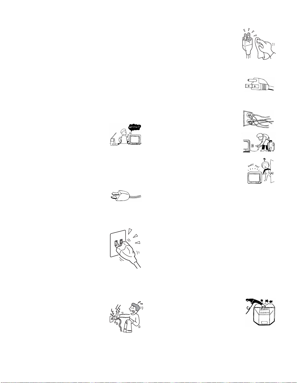
Moisture
Do not touch the AC power cord with a wet hand.
If you plug/unplug the AC power cord with a wet
hand, it may cause electric shock.
Cleaning
Clean the AC power plug regularly.
If the plug is covered with dust and it picks up
moisture, its insulation may deteriorate and result in
fire. Unplug the AC power plug and clean it
regularly.
For the set with a three-wire grounding type AC
plug
This plug will only fit into a grounding-type power
outlet. This is a safety feature. If you are unable to
insert the plug into the outlet, contact your electrician
to have a suitable outlet installed. Do not defeat the
safety purpose of the grounding plug.
Overloading
Do not overload wall outlets, extension cords or
convenience receptacles beyond their capacity, since
this can result in fire or electric shock.
Always turn the set off when it is not being used.
When the set is left unattended and unused for long
periods of time, unplug it from the wall outlet as a
precaution against the possibility of an internal
malfunction that could create a fire hazard.
If a snapping or popping sound from a TV set is
continuous or frequent while the TV is operating,
unplug the TV and consult your dealer or service
technician. It is normal for some TV sets to make
occasional snapping or popping sounds, particularly
when being turned on or off.
AC power cord and display cable
If you damage the AC power cord or display cable, it may result in fire or
electric shock.
s Do not pinch, bend, or twist the cable excessively. The core lines
may be bared and cut, and cause short-circuit, resulting in fire or
electric shock.
s Do not convert or damage the AC power cord or display cable.
s Do not put anything heavy on the AC power cord or display cable.
Do not pull the AC power cord or display cable.
s Keep the AC power cord or display cable away from heat sources.
s Be sure to grasp the plug when disconnecting the AC power cord.
s Refer to the operating instructions when disconnecting the display
cable.
If the AC power cord or display cable is damaged, stop using it and ask
your dealer or Sony service center to exchange it.
Cleaning
Unplug the AC power cord when cleaning this unit. If not, it may result in
electric shock.
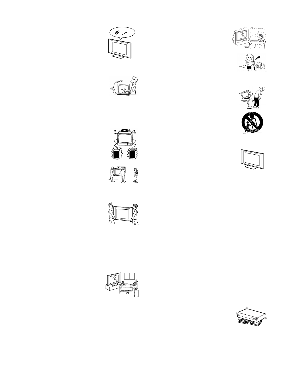
Object and Liquid Entry
Never push objects of any kind into the set through the
cabinet slots as they may touch dangerous voltage
points or short out parts that could result in a fire or
electric shock. Never spill liquid of any kind on the
set.
(Continued)
3
Ventilation holes
Do not insert anything in the ventilation holes. If
metal or something flammable enters, it may result in
fire or electric shock.
Cleaning
Clean the cabinet of the TV with a dry soft cloth. To
remove dust from the screen, wipe it gently with a soft
cloth. Stubborn stains may be removed with a cloth
slightly dampened with a solution of mild soap and
warm water. Never use strong solvents such as thinner
or benzine for cleaning.
If the picture becomes dark after using the TV for a long period of time, it
may be necessary to clean the inside of the TV. Consult qualified service
personnel.
Attachments
Do not use attachments not recommended by the
manufacturer, as they may cause hazards.
Installation
When installing the display unit on the wall, be sure to
have assemblers install and keep away from the unit.
If a person other than the assemblers install the display
unit on the wall using a wall mount unit, the unit may
fall and cause serious injury when an earthquake
occurs or when the unit is not installed securely.
Carrying
Carrying the set requires two or more people.
If you carry the set in a manner other than that
specified, it may drop and a serious injury may be
caused. Be sure two or more people carry the set.
When transporting, do not subject the set to shocks or
vibration excessive force. The set may fall and damage the set, causing
serious injury.
AC power cord
Unplug the AC power cord when moving the set.
Do not move the set with the AC power cord plugged in. It may damage
the AC power cord and result in fire or electric shock.
Medical institution
Do not place this unit in a place where medical
equipment is in use.
It may cause malfunction of medical instrume nts .
Water and Moisture
Do not use power-line operated sets near
water — for example, near a bathtub, washbowl,
kitchen sink, or laundry tub, in a wet basement, or
near a swimming pool, etc. It may result in fire or
electric shock.
Accessories
Do not place the set on an unstable cart, stand, table or
shelf. The set may fall, causing serious injury to a child
or an adult and serious damage to the set. Use only a
cart or stand recommended by Sony for the specific
model of TV. No part of the TV set should overhang
any edge of the TV cart or stand; any overhanging edge
is a safety hazard. An appliance and cart combination
should be moved with care. Quick stops, excessive
force, and uneven surfaces may cause the appliance and
cart combination to overturn.
Installation and moving
Optional accessories
Observe the following when installing the display unit
using a stand or wall mount unit. If not, the unit may fall
and cause serious injury.
s Be sure to follow the operating instructions
supplied with your stand when installing the unit.
s Be sure to attach the brackets supplied with your
stand.
Protruding location
Do not install the display unit in protruding locations. If you install the unit
in the following locations, injury may result.
s Do not install the unit in a location where the unit protrudes, such as
pillars.
s Do not install the unit in a location that may cause facial injury.
Oils
Do not install this unit in restaurants where oily vapours occur. Dust
absorbing oil may enter into the unit and damage the unit.
Corrosion
If you use this unit near the seashore, salt may corrode metal parts of the
unit and cause internal damage or fire.
It may also shorten the life of the unit.
Accessories
Secure the display unit from falling down.
If the display unit is not secured properly, it may fall and cause injury. Take
measures against it using a stand or other apparatus on the floor or wall in
the specified manner, referring to the operating instructions supplied with
your stand.
Recommended place for the Media receiver unit
Place the Media receiver unit on a stabl e, level surface.
Otherwise, the Media receiver unit may fall and cause
injury. Use an optional Sony stand, which has adequate
strength.
Weight
Do not stand on the Media receiver unit. The unit may fall or break, causing
injury. Pay special attention to little children.
4
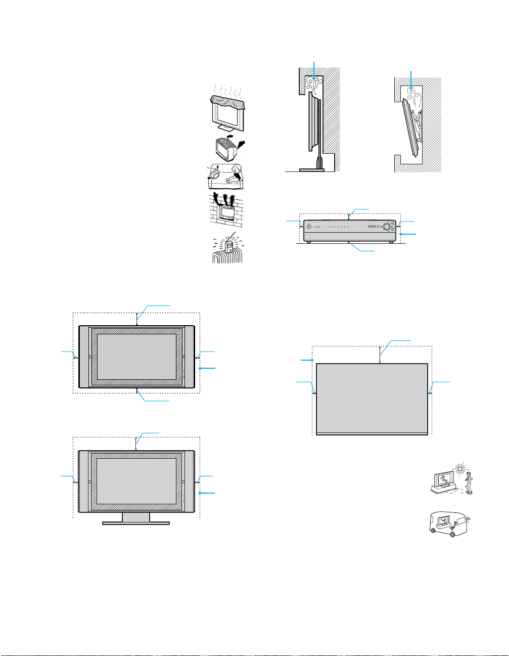
Ventilation
The slots and openings in the media receiver unit and display unit are
provided for necessary ventilation. To ensure reliable operation of the set,
and to protect it from overheating, these slots and openings must never be
blocked or covered.
Unless proper ventilation is provided, the unit may gathe r
dust and get dirty. For proper ventilation, Observe the
following:
s Do not install the unit turned backward or sideways.
s Do not install the unit turned over or upside down.
s Never cover the slots and openings with a cloth or
other materials.
s Never block the slots and openings by placing the set
on a bed, sofa, rug or other similar surface.
Never install the unit as follows:
Air circulation is b locked.
Air circulation is
blocked.
s Never place the set in a confined space, such as a
bookcase or built-in cabinet, unless proper ventilation
is provided.
s Do not place the set near or over a radiator or heat
register, or where it is exposed to direct sunlight.
Ventilation
Leave some space around the unit. Otherwise, adequate air-circulation may
be blocked causing overheating and cause fire or damage the unit.
When installing the unit on the wall
30 cm (11
10 cm
(4 in)
10 cm (4 in)
When installing the unit using a stand
30 cm (11
10 cm
(4 in)
7
/8 in)
7
/8 in)
10 cm
(4 in)
Leave
this
space at
least.
10 cm
(4 in)
Leave
this
space at
least.
Media receiver unit: Front view
7
7 cm (2
/8 in)
5 cm
(2 in)
PC
654321
MEMORY STICK
PROG
PROG
1 cm (
13
in)
/32
5 cm (2 in)
Leave this
space at least.
Place the Media receiver unit on a stable level surface so as not to block the
inlets at the bottom of the Media receiver unit.
Media receiver unit: Top view
Never place the Media receiver unit in a confined space. It may cause
overheating and result in fire, or damage the unit. Ensure reliable operation
of the unit by ensureing proper ventilation of the exhaust fan.
10 cm (4 in)
Leave this
space at
least.
5 cm
(2 in)
5 cm
(2 in)
Outdoor use
Do not install this unit outdoors. If the unit is exposed to
rain, it may result in fire or electric shock. If the unit is
exposed to direct sunlight, the unit may heat up and it may
damage the unit.
Vehicle and ceiling
Do not install this unit in a vehicle or hung from the
ceiling.
Bumping of the vehicle may cause the set to fall down and
cause injury.
(Continued)
5
Ship and vessel
Do not install this unit in a ship or vessel. If the unit is
exposed to seawater, it may cause fire or damage the unit.
Antenna Grounding According to the National
Electrical Code, ANSI/NFPA 70
Carrying
Carrying the set requires two or more people.
If you carry the set in a manner other than that specified, it may drop and a
serious injury may be caused. Be sure two or more people carry the set.
When transporting, do not subject the set to shocks or vibration, or
excessive force. The set may fall and be damaged, causing serious injury.
AC power cord
Unplug the AC power cord when moving the set.
Do not move the set with the AC power cord plugged in. It may damage
the AC power cord and result in fire or electric shock.
Fall
Do not hang anything on the unit.
The unit may fall from the stand or wall mount unit, causing
damage or serious injury.
Power-Cord Protection
Do not allow anything to rest on or roll over the
power cord, and do not place the set where the
power cord is subject to wear or abuse.
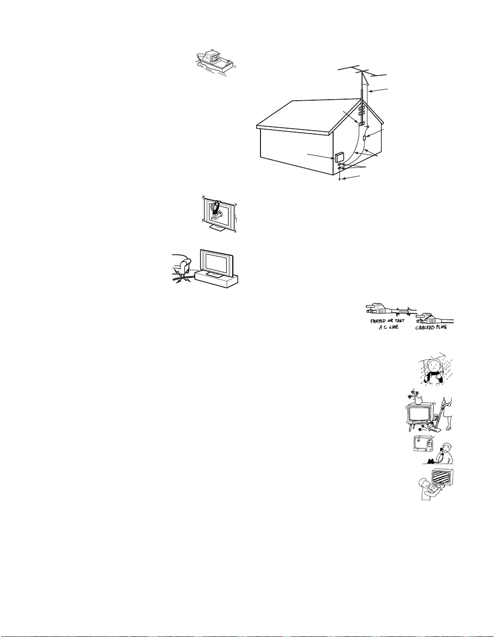
Antennas
Outdoor Antenna Grounding
If an outdoor antenna is installed, follow the precautions below. An
outdoor antenna system should not be located in the vicinity of overhead
power lines or other electric light or power circuits, or where it can come
in contact with such power lines or circuits.
WHEN INSTALLING AN OUTDOOR ANTENNA SYSTEM,
EXTREME CARE SHOULD BE TAKEN TO KEEP FROM
CONTACTING SUCH POWER LINES OR CIRCUITS AS CONTACT
WITH THEM IS ALMOST INVARIABLY FATAL.
Be sure the antenna system is grounded so as to provide some protection
against voltage surges and built-up static charges.
Section 810 of the National Electrical Code (NEC) in USA and Section 54
of the Canadian Electrical Code in Canada provides information with
respect to proper grounding of the mast and supporting structure,
grounding of the lead-in wire to an antenna discharge unit, size of
grounding conductors, location of antenna discharge unit, connection to
grounding electrodes, and requirements for the grounding electrode.
Antenna lead-in wire
Ground clamps
Antenna discharge unit
Electric service
equipment
NEC: National Electrical Code
(NEC Section 810-20)
Grounding conductors
(NEC Section 810-21)
Ground clamps
Power service grounding
electrode system
(NEC Art 25 0 Part H)
Lightning
For added protection for this television receiver during a lightning storm,
or when it is left unattended and unused for long periods of time, unplug it
from the wall outlet and disconnect the antenna. This will prevent damage
to the receiver due to lightning and power-line surges.
Service
Damage Requiring Service
Unplug the set from the wall outlet and refer servicing to qualified service
personnel under the following conditions:
s When the power cord or plug
is damaged or frayed.
s If liquid has been spilled into
the set.
s If the set has been exposed to rain or water.
s If the set has been subject to excessive shock by
being dropped, or the cabinet has been
damaged.
s If the set does not operate normally when
following the operating instructions. Adjust only
those controls that are specified in the operating
instructions. Improper adjustment of other
controls may result in damage and will often
require extensive work by a qualified technician
to restore the set to normal operation.
s When the set exhibits a distinct change in
performance, it indicates a need for service.
6
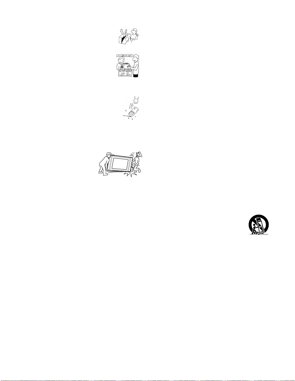
Servicing
Do not attempt to service the set yourself since opening the
cabinet may expose you to dangerous voltage or other
hazards. Refer all servicing to qualified service personnel.
Replacement Parts
When replacement parts are required, be sure the service
technician certifies in writing that he has used
replacement parts specified by the manufacturer that
have the same characteristics as the original parts.
Unauthorized substitutions may result in fire, electric
shock or other hazards.
Safety Check
Upon completion of any service or repairs to the set, ask the
service technician to perform routine safety checks (as
specified by the manufacturer) to determine that the set is in
safe operating condition, and to so certify. When the set
reaches the end of its useful life, improper disposal could
result in a picture tube implosion. Ask a qualified service
technician to dispose of the set.
For Safety
Be careful wh en moving the TV
When you place the TV in position, be careful
not to drop it on your foot or fingers.
Watch your footing while installing the TV.
Carry the TV in the specified manner
If you carry the TV in a manner other than specified and without the
specified number of persons, it may drop and a serious injury may be
caused. Be sure to follow the instructions mentioned below.
s Carry the TV with the specified number of persons.
s Do not carry the TV holding the speaker grill.
s Hold the TV tightly when carrying it.
The TV includes handles that you can use to carry the unit.
Others
Damage requiring service
If the surface of the display unit cracks, do not touch it until you unplug the
AC power cord.
Otherwise electric shock may result.
Object placement
Do not place something heavy on the Media receiver unit.
It may damage the unit.
Liquid placement
Do not place objects containing liquid on the Media receiver unit.
It may result in electric shock or damage the unit.
Moisture
Do not let this unit get wet. It may result in electric shock or damage the
unit.
Electric shock
Do not touch the unit with a wet hand.
Doing so may cause electric shock or damage to the unit.
Broken pieces
Do not throw anything at the unit.
The screen glass may explode by the impact and cause serious injury.
Cable wiring
Take care not to catch your feet on the cables. It may damage the unit.
Heat
Do not touch the surface of the display unit.
It remains hot, even for some time after the di splay unit is turned off.
Important Safety Instruction
1) Read these instructions.
2) Keep these instructions.
3) Heed all warnings.
4) Follow all instructions.
5) Do not use this apparatus near water.
6) Clean only with dry cloth.
7) Do not block any ventilation openings. Install in accordance with the
manufacturer’s instructions.
8) Do not install near any heat sources such as radiators, heat registers,
stoves, or other apparatus (including amplifiers) that produce heat.
9) Do not defeat the safety purpose of the polarized or grounding-type
plug. A polarized plug has two blades with one wider than the other.
A grounding type plug has two blades and a third grounding prong.
The wide blade or the third prong are provided for your safety. If the
provided plug does not fit into your outlet, consult an electrician for
replacement of the obsolete outlet.
10) Protect the power cord from being walked on or pinched particularly
at plugs, convenience receptacles, and the point where they exit from
the apparatus.
11) Only use attachments/accessories specified by the manufacturer.
12) Use only with the cart, stand, tripod, bracket, or table specified by the
manufacturer, or sold with the apparatus. When a cart is used, use
caution when moving the cart/apparatus combination to avoid injury
from tip-over.
13) Unplug this apparatus during lightning storms or when unused for
long periods of time.
14) Refer all servicing to qualified service personnel. Servicing is
required when the apparatus has been damaged in any way, such as
power-supply cord or plug is damaged, liquid has been spilled or
objects have fallen into the apparatus, the apparatus has been exposed
to rain or moisture, does not operate normally, or has been dropped.
7


Contents
Introducing the TV
Setting Up the TV
Welcome...............................................................................................13
Package Contents..........................................................................13
Features.........................................................................................13
Overview ..............................................................................................15
TV Controls and Connectors.............................................................. 16
Display unit.....................................................................................16
Media receiver unit Front Panel.....................................................17
Media receiver unit Rear Panel......................................................18
Installing the TV.......................................... ...... ................................. ..20
Basic Connections: Connecting a Cable or Antenna......................22
Cable or Antenna Only...................................................................23
Cable and Antenna Only................................................................24
Cable Box and Cable Only.............................................................25
Cable Box Only..............................................................................27
Connecting Optional Equipment .......................................................29
About Using S VIDEO .................................................. ..... ...... ..... ..29
VCR and Cable..............................................................................30
VCR and Cable Box.......................................................................32
Two VCRs for Tape Editing............................................................34
Satellite Receiver...........................................................................36
Satellite Receiver and VCR............................................................38
DVD Player with Component Video Connectors ............................40
DVD Player with S VIDEO and Audio Connectors.........................42
Digital TV Set-Top Box with Component Video Connectors..........43
Digital Satelite Receiver with DVI-HDTV connector....................... 44
Camcorder .....................................................................................45
Audio Receiver...............................................................................46
Sub Woofer....................................................................................47
Using the CONTROL S Feature..........................................................48
Setting Up the Channel List ...............................................................49
Using Auto Setup...........................................................................49
9

Using the Remote Control
Using the Features
Overview ..............................................................................................51
Inserting Batteries...............................................................................51
Button Descriptions............................................................................52
Programming the Remote Control.....................................................54
Using Other Equipment with Your TV Remote Control ...................56
All Equipment.................................................................................56
Operating a VCR............................................................................56
Operating a Satellite Receiver .......................................................56
Operating a Cable Box...................................................................57
Operating a DVD Player.................................................................57
Operating an MDP (Laserdisc Player) ...........................................57
Overview ..............................................................................................59
Watching TV.........................................................................................60
Using Wide Mode ................................................................................61
Using Twin View..................................................................................62
Displaying Twin Pictures................................................................62
Activating the Picture ........................................................ ...... ..... ..63
Changing the Picture Size..............................................................64
Using Favorite Channels....................................................................65
Creating a List of Favorite Channels..............................................65
Displaying a List of Favorite Channels...........................................65
Using the Freeze Function .................................................................66
Using Picture Off................................................................................. 67
Using the Memory Stick Picture Viewer............................................68
About Memory Stick............................................... ........................68
Supported Image Types.................................................................68
Unsupported Image Types................................................ ...... ..... ..69
Inserting and Removing a Memory Stick .......................................70
Displaying the Memory Stick Menu................................................72
Using the Memory Stick Index .......................................................73
Using the Memory Stick Slideshow................................................74
Changing the Memory Stick Setup Options...................................74
Using the Rotate Picture Screen....................................................75
10

Using the Menus
Other Information
Overview ..............................................................................................77
Navigating Through Menus................................................................77
Using the Video Menu.........................................................................78
Selecting Video Options.................................................................78
Using the Audio Menu ........................................................................80
Selecting Audio Options.................................................................80
Using the Screen Menu.......................................................................82
Selecting Screen Mode Options.....................................................82
Using the Channel Menu ....................................................................84
Selecting Channel Options.............................................................84
Using the Parent Menu .......................................................................86
Selecting Parent Options...............................................................86
US Models: Selecting Custom Rating Options...............................87
Viewing Blocked Programs............................................................ 87
Canadian Models: Selecting Custom Rating Options....................88
Viewing Blocked Programs............................................................ 88
Using the Setup Menu.........................................................................89
Selecting Setup Options.................................................................89
Overview ..............................................................................................93
Glossary...............................................................................................94
Notes on Using Memory Stick Media ................................................95
Memory Stick Precautions.............................................................95
Contacting Sony..................................................................................96
Troubleshooting..................................................................................96
Twin View.......................................................................................96
Remote Control..............................................................................97
Memory Stick .................................................................................97
Video..............................................................................................98
Audio..............................................................................................99
Channels........................................................................................99
General ........................................................................................100
Specifications....................................................................................101
Optional Accessories............................................................. ...... .....103
Index...................................................................................................104
11


Introducing t he TV
Welcome
Thank you for purchasing the Sony Flat Panel Color TV. This manual is to
be used with the following models:
s KE-42XBR900
s KE-50XBR900
Package Contents The package contains the following:
s Flat panel display unit (PDM-5000 or PDM-4200)
s Media receiver unit (MBT-XBR900)
s Remote control (RM-927Y) and two size AAA (LR03) batteries
s Two AC power cords
s AC plug holder
s Dis play interface cable
s Antenna cable
s Cleaning cloth
s Operating Instructions
These items are all you need to set up and operate the TV in its basic
configuration.
Most components (VCRs, DVD players, etc.) come with the necessary
cables to connect them. If you want to set up a complex system, you may
need to buy extra cables, connectors, etc. Be sure to have these on hand
before you start to connect your system.
Features Some of the features that you will enjoy with your new TV include:
s WEGA Engine
source by minimizing the signal deterioration caused by digital-toanalog conversion and stabilizing the signal processing. This engine
features unique Sony technology, including:
• The first step in the digital processing system, Composite
Component Processor (CCP), which enhances input signal to noise
ratio by chroma decoder degital processing;
™
: Delivers superb picture quality from any video
(Continued)
13

Welcome
• DRC® (Digital Reality Creation) Multifunction V1: Unlike
conventional line doublers, the DRC Multifunction feature replaces
the signal’s NTSC waveform with the near-HD equivalent by digital
mapping processing. The DRC Palette option lets you customize the
level of detail (Reality) and smoothness (Clarity) to create up to three
custom palettes.
• Multi-Image Driver (MID
™
-XU): (Twin View™) Allows you to
watch two programs side by side. You can watch pictures from two
different sources (1080i, 720p, 480p, and 480i) simultaneously.
(Only the left Twin Vie w win dow can display 10 80i, 720p, and 480p
sources.)
• CineMotion
™
: Provides an optimized display by automatically
detecting film content and applying a reverse 3/2 pulldown process.
Moving pictures will appear clearer and more natural-looking.
• Newly developed PDP driver IC: Achieves high-precision gamma
characteristics, using Sony’s unique digital technology. Fine
gradation of dark scenes, which is not possible with conventional
PDP , is realized by greatly enhancing resolution in the low brightness
range.
s Wide Screen Mode: Watch conventional 4:3 aspect ratio broadcasts in
wide screen (16:9) mode.
s Favorite Channels: Allows you to preview and select from eight of
your favorite channels.
s Steady Sound
®
: Equalizes volume levels so there is consistent output
between programs and commercials.
s Memory Stick
®
Picture Viewer: Allows you to view on your TV
screen digital images that are stored on Memory Stick media.
s Co mponent Video Inputs: Offers the best video quality for DVD
(480p, 480i), and digital set-top box (HD1080i, 720p) connections.
s HD Detailer
™
: Wideband video amplifier has a high bandwidth
frequency rating, which allows it to send more video information to the
screen, resulting in finer picture quality, especially for HD sources.
s Parental Control: V-Chip technology allows parents to block
unsuitable programming from younger viewers.
s Digital Visual Interface (DVI-HDTV): Can accommodate a copy-
protected digital connection (HDCP
*
) to other devices (such as digital
set-top boxes) that have compatible interfaces. The DVI-HDTV input
terminal is compliant with the EIA-861 standard and is not intended for
use with per s onal computers.
14
* High-bandwidth Digital Content Protection

Setting Up the TV
Overview
This chapter includes illustrated instructions for setting up your TV.
Topic Page(s)
TV Controls and Connectors 16-18
Installing the TV 20
Basic Connections: Connecting a Cable or Antenna 22-27
Connecting Optional Equipment
VCR and Cable
VCR and Cable Box
Two VCRs for Tape Editing
Satellite Receiver
Satellite Receiver and VCR
DVD Player with Component Video Connectors
DVD Player with S VIDEO and Audio Connectors
Digital TV Set-Top Box with Component Video Connectors
Digital Satelite Receiver with DVI-HDTV connector
Camcorder
Audio Receiver
Sub woofer
Using the CONTROL S Feature 48
Setting Up the Channel List 49
30
32
34
36
38
40
42
43
44
45
46
47
15
TV Controls and Connectors
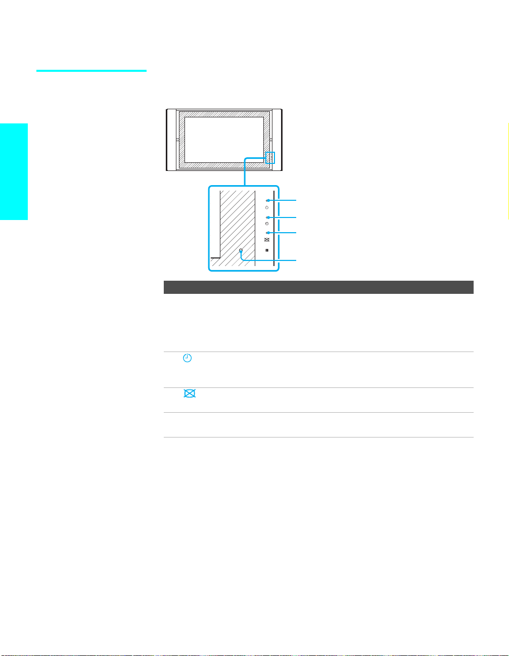
Display unit
Setup
Item Description
1 1 POWER
2 TIMER LED When lit, indicates one of the timers is set. When the timer
3 PICTURE
4 Infrared
ON/STAND BY
LED
OFF LED
Receiver (IR)
POWER ON/
STAND BY
TIMER
PICTURE
OFF
1
2
3
4
Lights up in green when the TV set is turned on. When in
standby mode, the LED li ghts up in red. The LED does not
light up when the main power is turned off. If the LED
blinks continuously, this may indicate the display unit
needs servicing (see “Contacting Sony” on page 96).
is set, this LED will remain lit even if the TV set is turned
off. For details, see page 89.
When lit, indicates that the Pictur e Off feature is activated.
For details, see page 67.
Receives IR signals from the TV’s remote control.
16
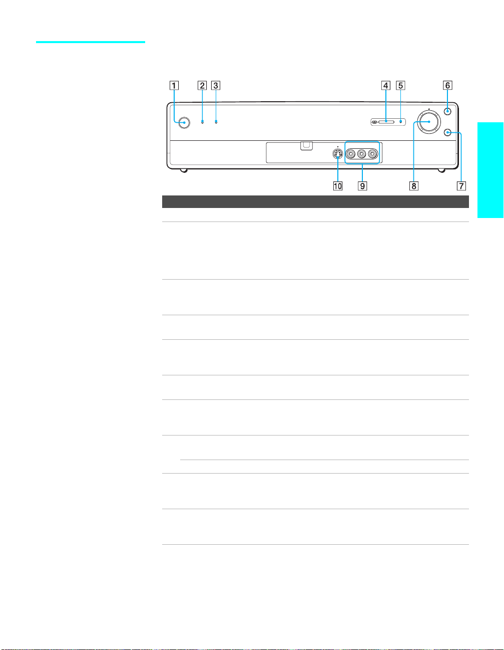
Media receiver unit Front Panel
INPUT SELECT
CHANNEL
POWER
POWER
TV VIDEO1 VIDEO2 VIDEO3 VIDEO4 VIDEO5 VIDEO6 MEMORY STICK
ON/OFF TIMER
S VIDEO
VIDEO
VIDEO 2 INPUT
–AUDIO–
LR
+
VOL
–
VOL
+
CHANNEL
–
MTS/SAP
Item Description
1 Main POWER Press to turn on and off the main power of the TV Set.
2 POWER LED Lights up in green when the TV set is turned on. The LED
lights up in red when in standby mode. The LED does not
light up when the main power is turned off. If the LED
blinks continuously, this may indicate the Media receiver
unit needs servicing (see “Contacting Sony” on page 96).
3 ON/OFF TIMER
LED
When lit, indicates one of the timers is set. When the timer
is set, this LED will remain lit even if the TV set is turned
off. For details, see page 89.
4 MEMORY
STICK
5 MEMORY
STICK ACCESS
Memory Stick insertion slot. For details, see “Inserting and
Removing a Memory Stick” on page 70.
When lit, indicates that the Memory Stick is being read.
(Do not remove the Mem ory Stick when the indica tor is lit.)
LED
6 INPUT SELECT Press repeatedly to cycle through the video equipment
connected to the Medi a receiver unit’s video inputs.
7 MTS/SAP Press repeatedly to cycle through the Multi-channel TV
Sound (MTS) options: Stereo, Auto SAP, and Mono. For
details on each option, see page 80.
8 – CHANNEL + Press to scan through channels. To scan quickly through
channels, press and hold down either CHANNEL.
– VOLUME + Press to adjust the volume.
9 VIDEO/
L-AUDIO-R
Connects to the composite A/V output jacks on your
camcorder or other video equipment.
VIDEO 2 INPUT
0 S VIDEO 2
INPUT
Connects to the S VIDEO OUT jack on your camc order or
other video equipment that has S VIDEO. Provides better
picture quality than composite video (9).
Setup
17
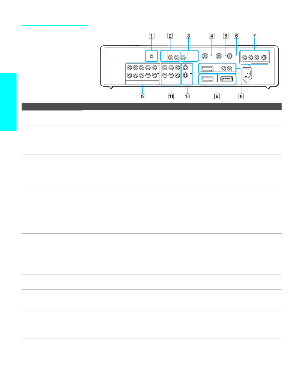
Media receiver unit Rear Panel
TO
CONTROL S
AV MOUSE
HD/DVD IN
OUT
BPR
AUDIO IN
R–AUDIO–L Y P
( 1080i / 720p / 480p / 480i )
Jack Description
Setup
1 CONTROL S OUT Allows the TV to send remote control signals to other Sony infrared-controlled audio or
R–AUDIO–L
AUDIO
OUT
(VAR/FIX) (VAR)
4
5
R–AUDIO–L
VIDEO S VIDEO
VIDEO IN
SUBWOOFER
OUT
1
3
VHF/UHF
DVI–HDTV
WHITE
DISPLAY SIGNAL OUT
video equipment tha t ha s the CO N TROL S function.
2 AUDIO OUT
(VAR/FIX) L/R
3 SUB WOOFER OUT
Connects to the left and right audio input jacks of your audio or video equipment. You can
use these outputs to listen to your TV’s audio through your stereo system.
Connects to the input jack of your sub woofer.
(VAR)
4 VHF/UHF Primary RF input that connects to your VHF/UHF antenna or cable.
5 TO CONVERTER Connects to your cable box input jack. This VHF/UHF output jack lets you set up your TV
to switch between scrambled channels (coming through a cable box) and unscrambled cable
channels. Use this jack instead of a splitter to get better picture quality when you need to
switch between scrambled and unscrambled cable channels. For details, see pages 24 and 25.
6 AUX Auxiliary RF input that connects to your antenna, CATV cable, or cable box output jack.
This is convenient if you are using two VHF/ UHF sources (antenna, CATV cable, or cable
box). For details, see pages 24 and 25.
7 MONITOR OUT Lets you record the program yo u are wa tching to a VCR. When two VCRs are connected,
you can use the T V a s a monitor for tape-to-tape editing (not available with 480p, 720p, or
1080i when the input is set to VIDEO 4-6).
8 DVI-HDTV IN
DVI-HDTV
AUDIO R/L
(VIDEO IN 6)
Can accommodate a copy-protected digital connection (HDCP*) to other devices (such as
digital set-top boxes) that ha ve compatible interfaces. The DVI-HDTV input terminal is
compliant with the EIA-861 standard and is not intended for use with personal computers.
See the instruction manual that came with your equipment for details about conne cting and
using it with the TV.
Use a DVI-D single link cable.
9 DISPLAY SIGNAL
OUT
Connects to the display input jack of the display unit by using the supplied display interface
cable.
0 S VIDEO IN 1/3 Connects to the S VIDEO OUT jack of your VCR or other video equipment that has
S VIDEO. S VIDEO provides bett er picture quality th an either composite vid eo (qa) or
VHF/UHF (4) connections .
qa VIDEO IN 1/3
VIDEO/
L-AUDIO-R
Connect to the composite A/V output jacks on your VCR or other video component. A third
component A/V input jack (VIDEO 2) is located on the front panel of the Media receiver
unit. These video connections provide better picture quality than the VHF/UHF (4)
connections.
CONVERTER
DVI–HDTV IN
AUX
R–AUDIO–L
BLACK
R–AUDIO–L VIDEO S VIDEO
6
MONITOR OUT
~ AC IN
18

Jack Description
qs HD/DVD IN 4/5
(1080i/720p/480p/
480i)
* High-bandwidth Digital Content Protection
Connect to your DVD player’s or digital set-top box’s component video (Y, PB, PR) and
audio (L/R) jacks. Component video provides better picture quality than 4, 0, or qa).
Setup
19
Installing the TV
Setup
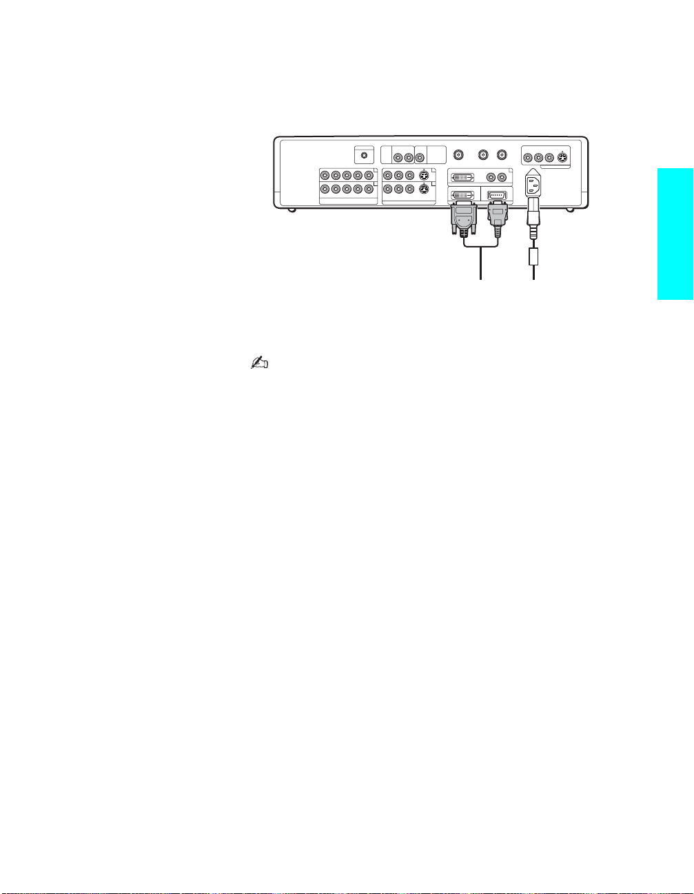
1 Connect the display interface cable (supplied) to the display unit’s DISPLAY
SIGNAL IN jack, and connect the AC power cord (supplied) to the display
unit’s AC IN jack.
Disconnect all power sources before making any connections.
SONY EXCLUSIVE CABLE ONLY
BLACK
DISPLAY SIGNAL IN
Display interface
cable (supplied)
2
Secure the AC power plug to the display’s AC IN jack.
AC IN (Power
supply input)
jack of the
display
AC power cord
(supplied)
1 Attach the AC plug holder
(supplied) to the AC
power cord.
AC plug holder
(supplied)
WHITE
Tighten the
screw slowly
until the
screw is
stabilized.
AC IN
AC Power cord
(supplied)
2 Clip on to the AC IN
jack until you hear
clicking.
20
When you unplug the AC power cord, drag the AC plug holder
down by pushing both sides of the holder, then pull out the
plug.
3
Install the display unit using an optional stand or rack unit.
For details, refer to the operating instructions supplied with your stand or rack unit.
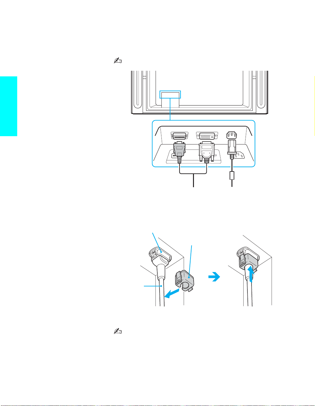
4 Connect the other end of display interface cable to the Media receiver unit’s
DISPLAY SIGNAL OUT jack, and connect the AC power cord (supplied) to the
media receiver unit’s AC IN jack.
TO
AUDIO IN
AV MOUSE
R–AUDIO–L Y P
HD/DVD IN
( 1080i / 720p / 480p / 480i )
CONTROL S
BPR
OUT
4
5
R–AUDIO–L
VIDEO S VIDEO
VIDEO IN
SUBWOOFER
AUDIO
OUT
(VAR/FIX) (VAR)
R–AUDIO–L
OUT
1
3
Tighten the screw slowly until
the screw is stabilized.
VHF/UHF
DVI–HDTV
CONVERTER
DVI–HDTV IN
WHITE
DISPLAY SIGNAL OUT
R–AUDIO–L
BLACK
AUX
R–AUDIO–L VIDEO S VIDEO
6
MONITOR OUT
~ AC IN
Setup
Display interface
cable (supplied)
AC power cord
(supplied)
5 After making all connections, connect the AC power cords (supplied) to wall
outlets.
Be sure to use the supplied AC power cords.
When connecting optional compon ents, do not conne ct the A C
power cords to wall outle ts until you ha ve completed makin g all
connections.
Do not tighten the screw s too m u c h. It m ay damage the screw s.
Handle the display interface cable with care. If you pull the
cable by catching your feet on the cable, this unit may fall and
cause injury.
Do not use damaged c ab le s, suc h as ca bles whose connector s
are deformed.
21

Basic Connections: Connecting a Cable or Antenna
The way in which you will connect your TV varies, depending on how your
home receives a signal (cable, cable box, antenna) and whether or not you
plan to connect a VCR.
If You Are Connecting See Page
Cable or Antenna Only
s No cable box or VCR
Cable and Antenna Only
s No cable box or VCR
Cable Box and Cable Only
s Cable box unscrambles only some channels
Setup
(usually premium channels)
s No VCR
Cable Box Only
s Cable box unscrambles all channels
s No VCR
If you are connecting a VCR
s See the connections described on pages 30 and 32.
23
24
25
27
22
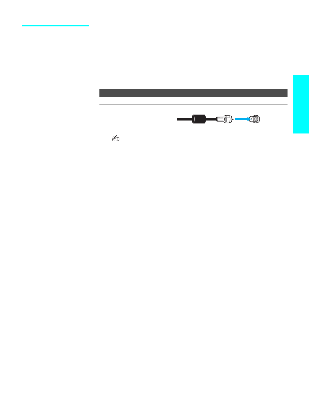
Cable or Antenna Only
For best results, use one of the following connections if you are
connecting a cable or an antenna and you:
s Do not need a cable box to unscramble channels. (If you have a cable
box, see page 27.)
s Do not intend to connect a VCR. (If you have a VCR, see pages 30 and
32.)
For antenna connection, use the supplied antenna cable.
75-ohm coaxial cable (usually found in newer homes)
Cable Type Connect As Shown
VHF Only or
combined
VHF/UHF or
Cable
When using an indoor antenna, such as rabbit-ear or dipoleantenna, keep the antenna away from the display unit. If not,
noise may appear on the screen.
Antenna
cable
(supplied)
Setup
VHF/UHF
23
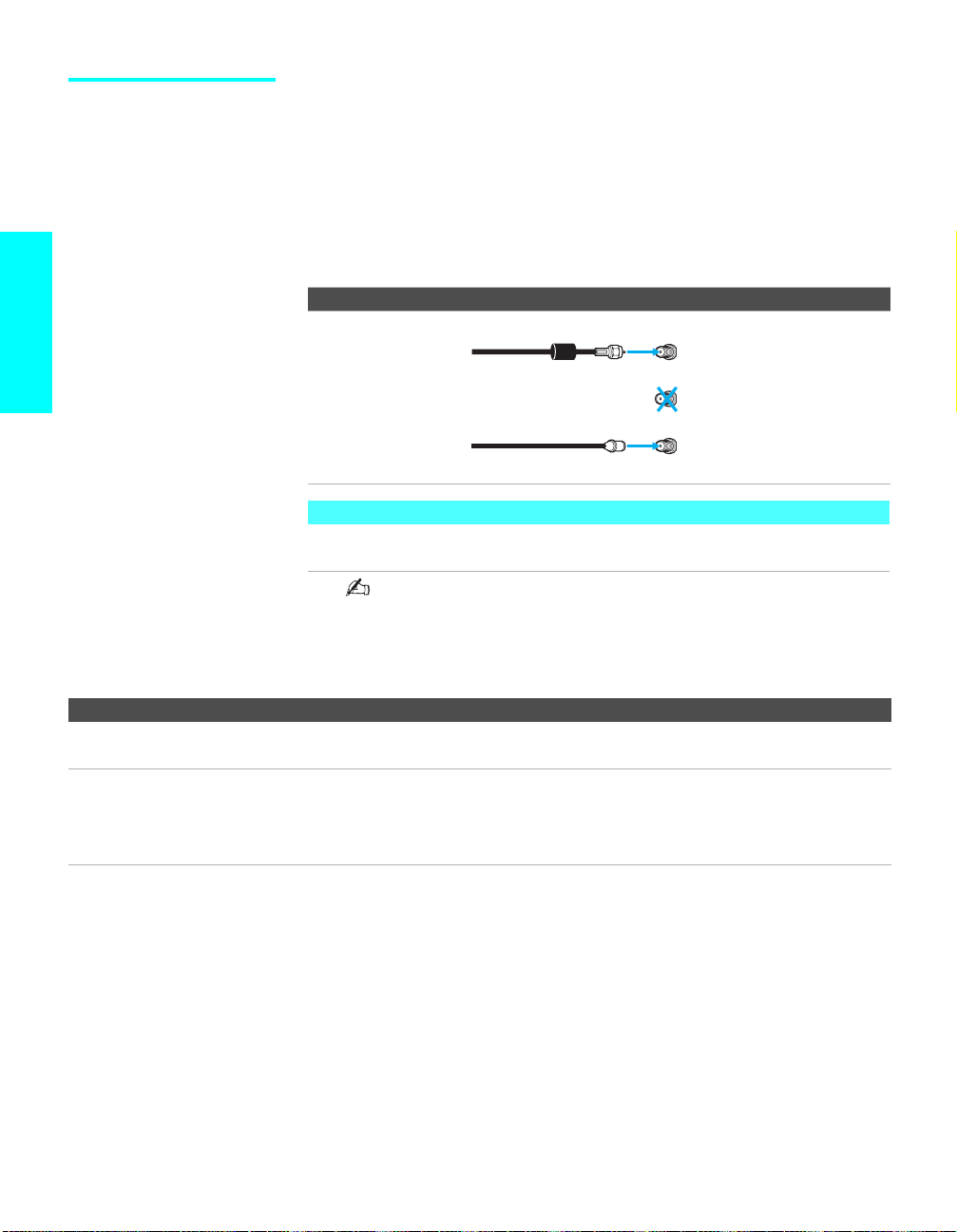
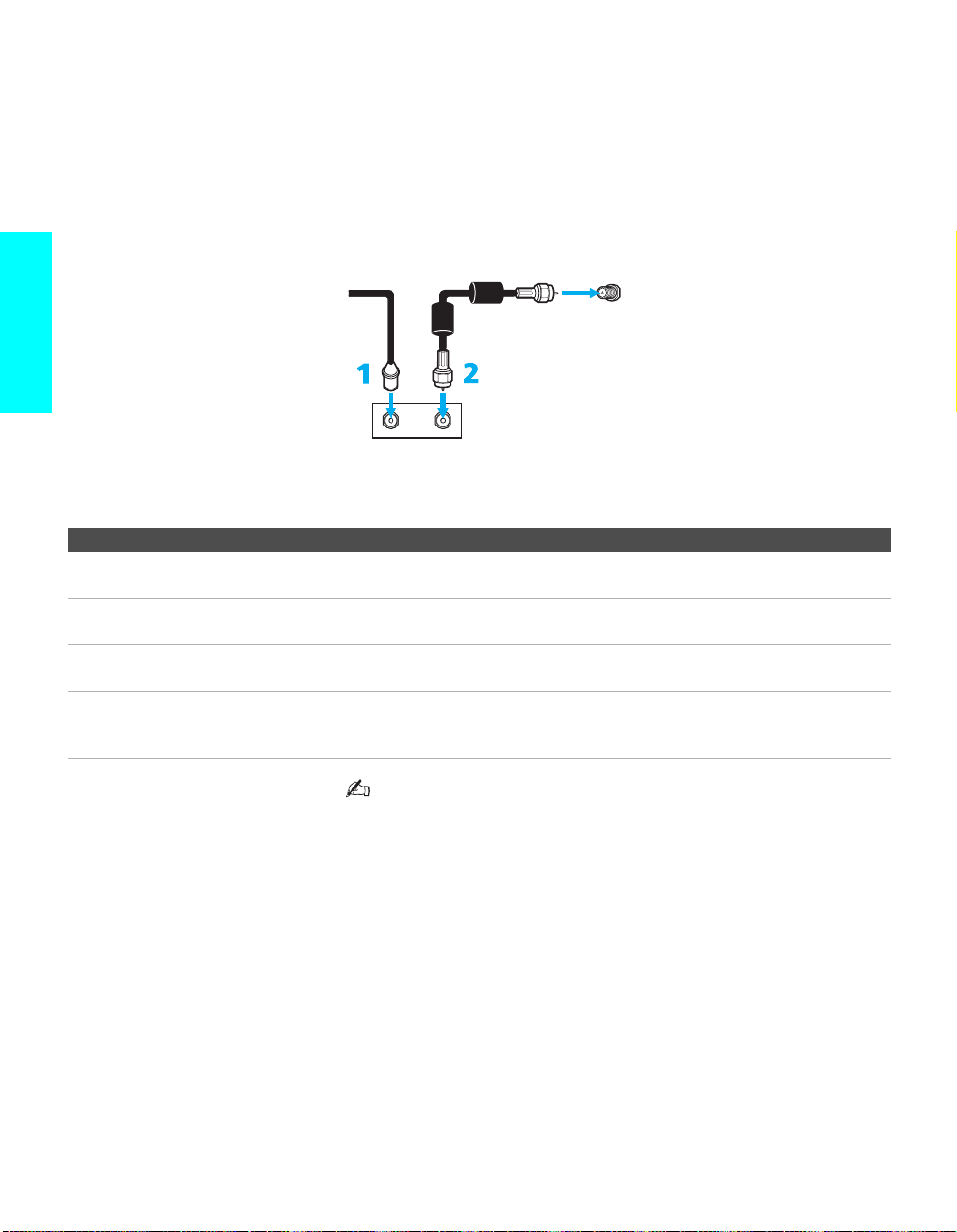
Cable and Antenna Only
Setup
For best results, use this connection if you:
s Have a cable and an antenna.
(This is con veni ent if you are u sing a separate rooftop ante nna to recei v e
additional channels that are not provided by your cable company.)
s Do not have a cable box or VCR. (If you have a cable box, see pages 25
to 27. If you have a VCR, see pages 30 and 32.)
For antenna connection, use the supplied antenna cable.
Cable Type Connect As Shown
Cable TV (CATV)
and Antenna
About Using This Connection with Dual Picture (Twin View, etc.) Features
With this connection, you cannot view antenna channels in the right dual picture
window.
When using an indoor antenna, such as rabbit-ear or dipoleantenna, keep the antenna away from the display unit. If not,
noise may appear on the screen.
Antenna cable (supplied)
TO CONVERTER
(No connection to
TO CONVERTER)
CATV cable
AUX
TV
VHF/UHF
Notes on Using This Connection
To Do This ... Do This ...
Switch the TV’s input between
the cable and antenna
Receive channels using an
antenna, instead of the cable
Press ANT to switch back and forth between the TV’s VHF/UHF and AUX inputs.
1 Press ANT to switch to the AUX input.
2 Set the Cable option to Off. For details, see “Selecting Channel Options” on
page 84.
3 Run the Auto Setup program, as described in “Us ing Auto Setup” on page 49.
24

Cable Box and Cable Only
For best results, use this connection if:
s Your cable company scrambles some channels, such as premium
channels (which requires you to use a cable b ox) , but does not scramble
all channels.
s You do not have a VCR. (If you have a VCR, see pages 30 and 32.)
With this connection you can:
s Use the TV remote control to change channels coming through the cable
box to the TV’s AUX input jack. (You must first program the remote
control for your specific cable box; see “Programming the Remote
Control” on page 54.)
s Use the TV remote control to change channels coming directly into the
TV’s VHF/UHF input. (The TV’s tuner provides a better signal than the
cable box.)
About Using This Connection with Dual Picture (Twin View, etc.) Features
With this connection, you can use all the dual picture features for unscrambled
channels coming directly into the TV’s VHF/UHF input jack.
However, you can use only some of the dual picture feature s fo r channels coming
through the cable box to the TV’s AUX input jack. For example, when you switch
the TV’s input to AUX — to select the cable box input — the picture displays only
in the left window. For example, if you turn on Twin View, you can watch cable
channels coming into the VHF/UHF jack in the right window, but you cannot swap
the pictures between the le ft and right windows.
Setup
(Continued)
25
Setup
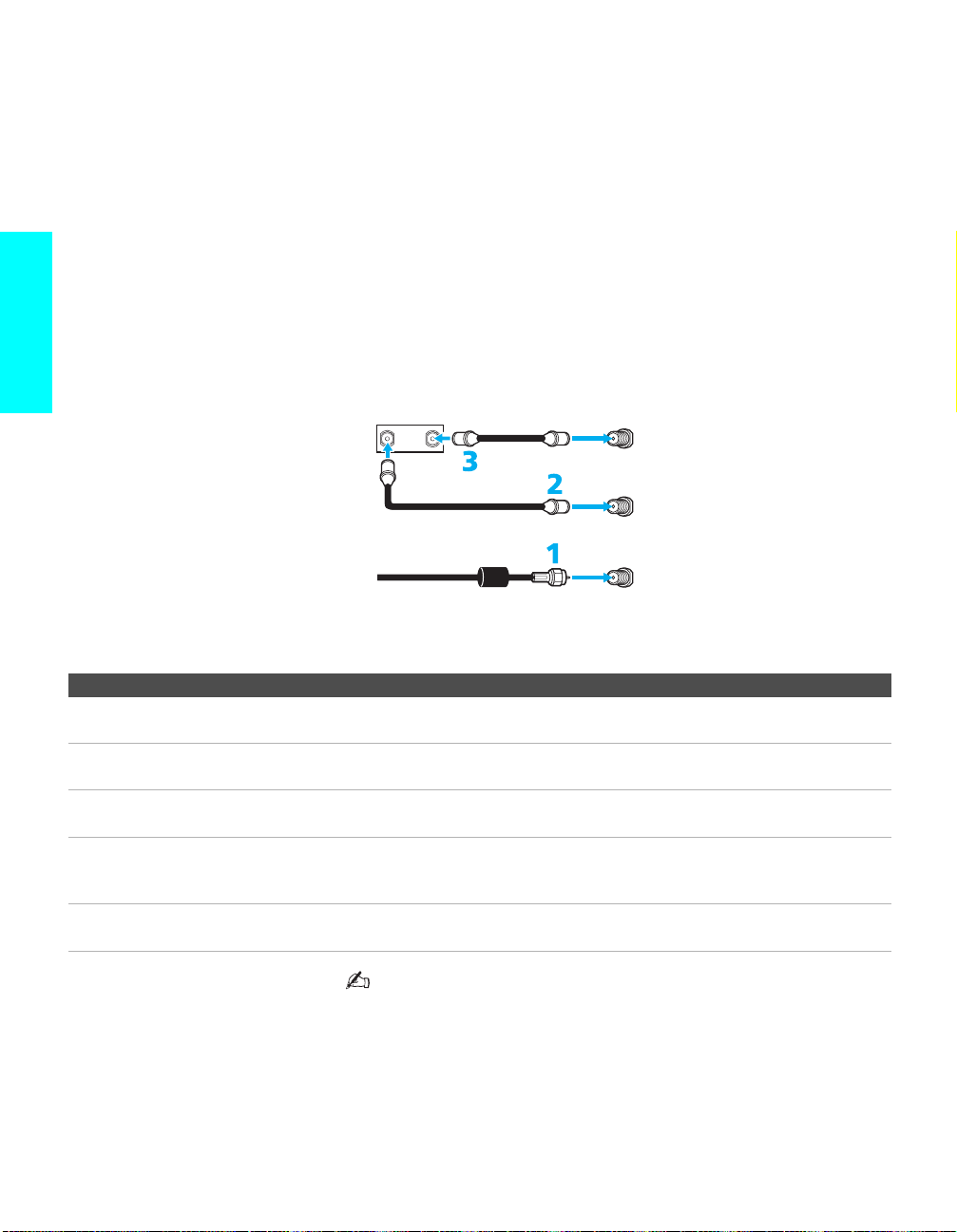
To connect the cable box and cable
1 Connect your cable company to the TV’s VHF/ UHF jack using the
supplied antenna cable.
2 Use a coaxial cable to connect the TV’s TO CONVERTER jack to the
cable box’s input jack. (The TV’s internal converter lets you switch
between unscrambled signals coming straight into the TV and
scrambled signals coming in through the cable box, eliminating the need
for an external splitter.)
3 Use a coaxial cable to connect the cable box’s output jack to the TV’s
AUX jack.
4 Run the Auto Setup program, as described in “Setting Up the Channel
List” on page 49.
Cable box
IN
OUT
75-ohm coaxial cable
(not supplied)
Antenna cable (supplied)
Notes on Using This Connection
To Do This ... Do This ...
Use the cable box Tune the TV to the channel the cable box is set to (usually channel 3 or 4) and then
use the cable box to switch channels.
Set up the TV remote control to
operate the cable box
Activate the remot e cont rol to
operate the cable box
Prevent the accidental switching
of TV channels
the TV’s input between
Switch
the cable box and cable
Program the re mote control. See “Programming the Remo te Control” on page 54.
Press SAT/CABLE FUNCTION repeatedly until the SAT/CABLE indicator lights
up.
When using the ca ble box, you need the TV to stay on the channel the cable box is
set to (usually channe l 3 o r 4). You can use the TV’s Channel Fix feature to lock in a
specific channel. For details, see “Using the Channel Menu” on page 84.
Press ANT to switch back and forth between the TV’s VHF/UHF (unscrambled
channels) and AUX (scrambled) inputs.
Coaxial cable
AUX
TO CONVERTER
TV
VHF/UHF
26
Do not leave the display indication of the cable box turned on.

Cable Box Only For best results, use this connection if:
s Your cable compan y scrambles all channels, which requires you to use a
cable box.
s You do not have a VCR. (If you have a VCR, see pages 30 and 32.)
With this connection you can:
s Use the TV remote control to change channels coming through the cable
box to the TV’s VHF/UHF jack. (You must first program the remote
control for your specific cable box.)
About Using This Connection with Dual Picture (Twin View, etc.) Features
With this connection, all channels come into the TV through your cable box and
only one unscrambled signal is sent to the TV, so you cannot use the dual picture
features.
Setup
(Continued)
27
To connect the cable box
1 Connect the CATV cable to the cable box’s input jack.
2 Use the supplied an tenna cable to con nect the cab le bo x’s output jack to
the TV’s VHF/UHF jack.
3 Run the Auto Setup program, as described in “Setting Up the Channel
List” on page 49.
CATV
cable
Antenna cable
(supplied)
VHF/UHF
Setup
OUTIN
Cable box
Notes on Using This Connection
To Do This ... Do This ...
Use the cable box Tune the TV to the channel the cable box is set to (usually channel 3 or 4) and then
use the cable box to switch channels.
Set up the TV remote control to
operate the cable box
Activate the remot e cont rol to
operate the cable box
Prevent the accidental switching
of TV channels
Program the re mote control. See “Programming the Remo te Control” on page 54.
Press FUNCTION repeatedly until the SAT/CABLE indicator lights up.
When using the ca ble box, you need the TV to stay on the channel the cable box is
set to (usually channe l 3 o r 4). You can use the TV’s Channel Fix feature to lock in a
specific channel. For details, see “Using the Channel Menu” on page 84.
Do not leave the display indication of the cable box turned on.
28
 Loading...