

Page 1

Flat Panel Color TV KE-32TS2U/KE-42TS2U
4-091-567-11 (2)
KE-32TS2U
KE-42TS2U
© 2002 Sony Corporation
US
FR
Operating Instructions
Mode d’emploi
ES
Manual de instrucciones
Page 2
WARNING
To Reduce the risk of fire or shock hazard,
do not expose the TV to rain or moisture.
CAUTION
RISK OF ELECTRIC SHOCK
DO NOT OPEN
ATTENTION
RISQUE DE CHOC ELECTRIQUE,
NE PAS OUVRIR
PRECAUCION
RIESGO DE CHOQUE ELECTRICO
NO ABRIR
CAUTION : TO REDUCE THE RISK OF ELECTRIC SHOCK,
DO NOT REMOVE COVER (OR BACK).
NO USER-SERVICEABLE PARTS INSIDE.
REFER SERVICING TO QUALIFIED SERVICE PERSONNEL.
This symbol is intended to alert the user to the
presence of uninsulated “dangerous voltage” within
the product’s enclosure that may be of sufficient
magnitude to constitute a risk of electric shock to
persons.
This symbol is intended to alert the user to the
presence of important operating and maintenance
(servicing) instructions in the literature
accompanying the appliance.
CAUTION
TO PREVENT ELECTRIC SHOCK, MATCH WIDE BLADE OF
PLUG TO WIDE SLOT, FULLY INSERT.
CAUTION
When using TV games, computers, and similar products with your
TV, keep the brightness and contrast functions at low settings. If a
fixed (non-moving pattern is left on the screen for long periods of
time at a high brightness or contrast setting, the image can be
permanently imprinted onto the screen. Continuously watching the
same program can cause the imprint of station logos onto the TV
screen. Theses types of imprints are not covered by your warranty
because they are the result of misuse.
Note on Caption Vision
This television receiver provides display of television closed
captioning in accordance with §15.119 of the FCC rules.
Notes on Cleaning the TV
Clean the TV with a soft dry cloth. Never use strong solvents such
as thinner or benzine, which might damage the finish of the cabinet.
Note on use in highlands
When used at an altitude of greater than 1900m or 6248 feet (air
pressure less than 800hPa), this Plasma Display Panel may generate
a low buzzing sound as a result of the difference between the interior
and exterior air pressure of the panels. This is not considered a
defect and is not covered under by the Limited Warranty. This
buzzing sound is an inherent characteristic of any Plasma Display
Panel.
2 (US)
Note to CATV system installer
This reminder is provided to call the CATV system installer’s
attention to Article 820-40 of the NEC that provides guidelines for
proper grounding and, in particular, specifies that the cable ground
shall be connected to the grounding system of the building, as close
to the point of cable entry as practical.
Use of this television receiver for other than private viewing of
programs broadcast on UHF, VHF, transmitted by cable companies
or satellite for the use of the general public may require
authorization from the broadcaster/cable company and/or program
owner.
NOTIFICATION
This equipment has been tested and found to comply with the limits
for a Class B digital device pursuant to Part 15 of the FCC Rules.
These limits are designed to provide reasonable protection against
harmful interference in a residential installation. This equipment
generates, uses, and can radiate radio frequency energy and, if not
installed and used in accordance with the instructions, may cause
harmful interference with radio communications. However, there is
no guarantee that interference will not occur in a particular
installation. If this equipment does cause harmful interference to
radio or television reception, which can be determined by turning the
equipment off and on, the user is encouraged to try to correct the
interference by one or more of the following measures:
– Reorient or relocate the receiving antennas.
– Increase the separation between the equipment and receiver.
– Connect the equipment into an outlet on a circuit different from
that to which the receiver is connected.
– Consult the dealer or an experienced radio/TV technician for help.
You are cautioned that any changes or modifications not expressly
approved in this manual could void your warranty and your
authority to operate this equipment.
Safety
– Operate the TV only on 120 V AC.
– The plug is designed, for safety purposes, to fit into the wall outlet
only one way. If you are unable to insert the plug fully into the
outlet, contact your dealer.
– If any liquid or solid object should fall inside the cabinet, unplug
the TV immediately and have it checked by qualified service
personnel before operating it further.
Installing
– To prevent internal heat buildup, do not block the ventilation
openings.
– Do not install the TV in a hot or humid place, or in a place subject
to excessive dust or mechanical vibration.
– The AC power cord is attached to the rear of the TV with hooks.
Do not attempt to remove the cord from these hooks. Doing so
could cause damage to the TV.
Owner’s Record
The model and serial numbers are provided on the front of this
instruction manual and at the rear of the TV. Refer to them whenever
you call upon your Sony dealer regarding this products.
CAUTION
The following SONY appliance(s) for use only with the following
TV STAND.
Use with other TV STAND is capable of resulting in instability
causing possible injury.
SONY APPLIANCE MODEL NO.
KE-32TS2U
KE-42TS2U
TV STAND MODEL NO.:
SU-TS1U
SONY ELECTRONICS INC.
Page 3
Important Safeguards
For your protection, please read these instructions completely, and keep this
manual for future reference.
Carefully observe and comply with all warnings, cautions and instructions
placed on the set or described in the operating instructions or service
manual.
WARNING
To guard against injury, the following basic safety precautions should be
observed in the installation, use and servicing of the set.
Use
Power Sources
This set should be operated only from the type of
power source indicated on the serial/model
plate. If you are not sure of the type of electrical
power supplied to your home, consult your
dealer or local power company. For those sets
designed to operate from battery power, refer to
the operating instructions.
Grounding or Polarization
This set is equipped with a polarized AC power cord plug (a plug having
one blade wider than the other), or with a three-wire grounding type plug
(a plug having a third pin for grounding). Follow the instructions below:
For the set with a polarized AC power cord plug
This plug will fit into the power outlet only one
way. This is a safety feature. If you are unable to
insert the plug fully into the outlet, try reversing
the plug. If the plug still fails to fit, contact your
electrician to have a suitable outlet installed. Do
not defeat the safety purpose of the polarized
plug by forcing it in.
Alternate Warning
For the set with a three-wire grounding type AC plug
This plug will only fit into a grounding-type power
outlet. This is a safety feature. If you are unable to
insert the plug into the outlet, contact your electrician
to have a suitable outlet installed. Do not defeat the
safety purpose of the grounding plug.
Overloading
Do not overload wall outlets, extension cords or
convenience receptacles beyond their capacity, since this
can result in fire or electric shock.
Always turn the set off when it is not being used. When
the set is left unattended and unused for long periods of
time, unplug it from the wall outlet as a precaution
against the possibility of an internal malfunction that
could create a fire hazard.
If a snapping or popping sound from a TV set is
continuous or frequent while the TV is operating, unplug
the TV and consult your dealer or service technician. It is
normal for some TV sets to make occasional snapping or
popping sounds, particularly when being turned on or
off.
Object and Liquid Entry
Never push objects of any kind into the set through the
cabinet slots as they may touch dangerous voltage
points or short out parts that could result in a fire or
electric shock. Never spill liquid of any kind on the set.
Cleaning
Unplug the set from the wall outlet before cleaning
or polishing it. Do not use liquid cleaners or aerosol
cleaners. Use a cloth lightly dampened with water
for cleaning the exterior of the set.
Installation
Attachments
Do not use attachments not recommended by the
manufacturer, as they may cause hazards.
Water and Moisture
Do not use power-line operated sets near water — for
example, near a bathtub, washbowl, kitchen sink, or
laundry tub, in a wet basement, or near a swimming pool,
etc.
Corrosion
Use of this set near the seashore may subject the set to excessive salt,
corrosion and internal damage and result in deterioration of the set’s
performance. If the set will be subjected to these conditions, steps should be
taken to reduce the humidity and temperature of the area where the set is
located.
Accessories
Do not place the set on an unstable cart, stand, table
or shelf. The set may fall, causing serious injury to a
child or an adult and serious damage to the set. Use
only a cart or stand recommended by Sony for the
specific model of TV. No part of the TV set should
overhang any edge of the TV cart or stand; any
overhanging edge is a safety hazard. An appliance and
cart combination should be moved with care. Quick
stops, excessive force, and uneven surfaces may cause the
appliance and cart combination to overturn.
Ventilation
The slots and openings in the cabinet and in the back or bottom are
provided for necessary ventilation. To ensure reliable operation of the set,
and to protect it from overheating, these slots and openings must never be
blocked or covered.
s Never cover the slots and openings with a cloth or
other materials.
s Never block the slots and openings by placing the set
on a bed, sofa, rug or other similar surface.
s Never place the set in a confined space, such as a
bookcase or built-in cabinet, unless proper ventilation
is provided.
s Do not place the set near or over a radiator or heat
register, or where it is exposed to direct sunlight.
Power-Cord Protection
Do not allow anything to rest on or roll over the power
cord, and do not place the set where the power cord is
subject to wear or abuse.
Carrying
This set should only be moved by two or more
people. If the set needs to be transported, it should
be protected to insure that it is not subject to
shock, vibration or excessive force.
Antennas
Outdoor Antenna Grounding
If an outdoor antenna is installed, follow the precautions below. An outdoor
antenna system should not be located in the vicinity of overhead power
lines or other electric light or power circuits, or where it can come in contact
with such power lines or circuits.
WHEN INSTALLING AN OUTDOOR ANTENNA SYSTEM, EXTREME
CARE SHOULD BE TAKEN TO KEEP FROM CONTACTING SUCH
POWER LINES OR CIRCUITS AS CONTACT WITH THEM IS ALMOST
INVARIABLY FATAL.
Be sure the antenna system is grounded so as to provide some protection
against voltage surges and built-up static charges. Section 810 of the
National Electrical Code (NEC) in USA and Section 54 of the Canadian
Electrical Code in Canada provides information with respect to proper
grounding of the mast and supporting structure, grounding of the lead-in
wire to an antenna discharge unit, size of grounding conductors, location of
antenna discharge unit, connection to grounding electrodes, and
requirements for the grounding electrode.
(US) 3
US
Page 4
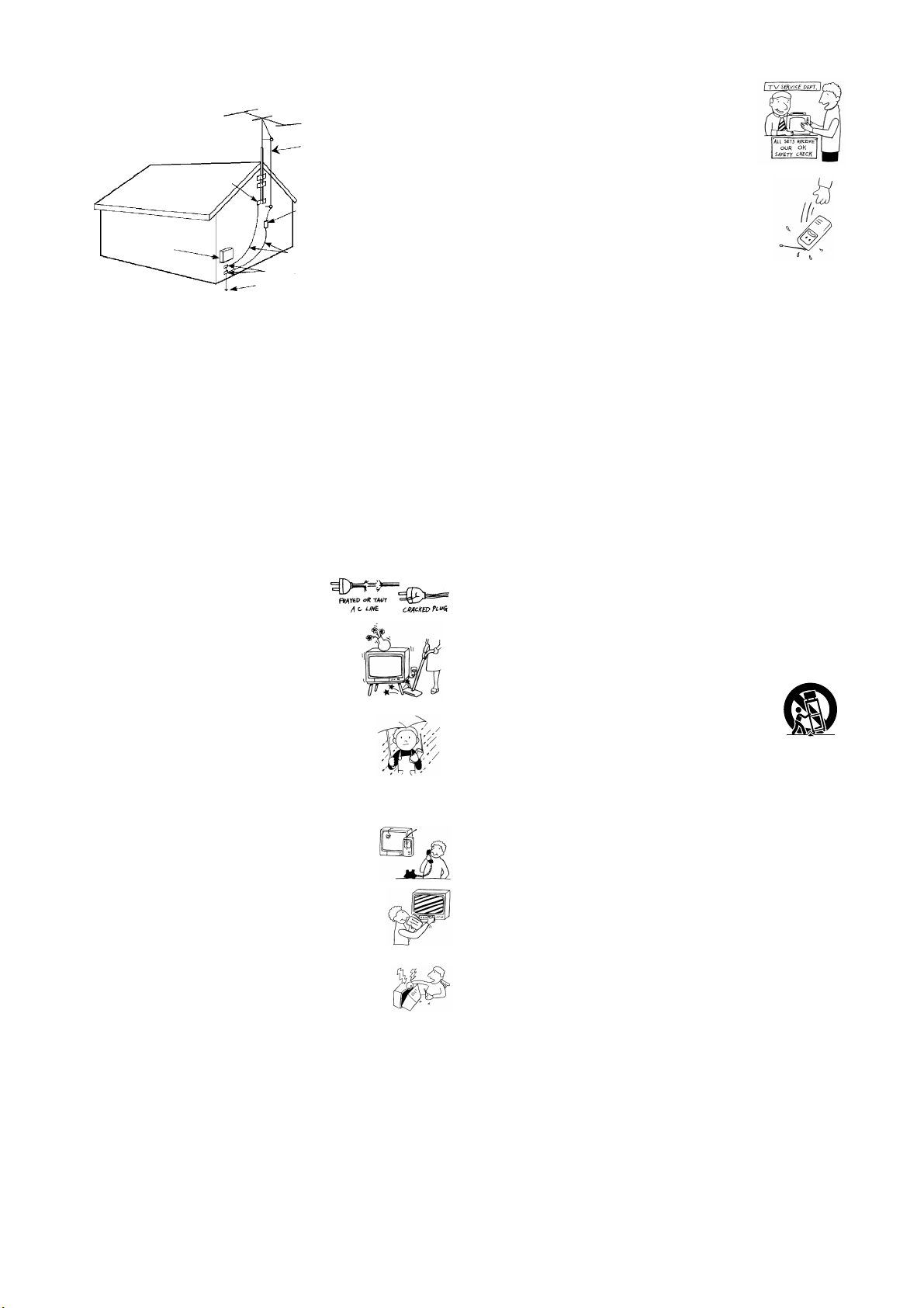
Antenna Grounding According to the NEC
Refer to section 54-300 of Canadian Electrical Code for Antenna Grounding.
Antenna lead-in wire
Ground clamp
Antenna discharge unit
(NEC Section 810-20)
Electrical wire
equipment
NEC: National Electrical Code
Ground clamps
Antenna lead-in wire
Power service grounding electrode
system (NEC Art 250 Part H)
Lightning
For added protection for this television receiver during a lightning storm, or
when it is left unattended and unused for long periods of time, unplug it
from the wall outlet and disconnect the antenna. This will prevent damage
to the receiver due to lightning and power-line surges.
Image retention
An image retention or ghost may appear on screen of the set if it a static
image is displayed on the screen for a period of time. To avoid this problem,
the “4:3 Default” or “Restore” mode should be used.
Refer to the operating instructions if an image retention or ghost appears.
Service
Damage Requiring Service
Unplug the set from the wall outlet and refer servicing to qualified service
personnel under the following conditions:
s When the power cord or plug is damaged or
frayed.
s If liquid has been spilled into the set.
Safety Check
Upon completion of any service or repairs to the set,
ask the service technician to perform routine safety
checks (as specified by the manufacturer) to
determine that the set is in safe operating condition,
and to so certify. When the set reaches the end of its
useful life, improper disposal could result in a
picture tube implosion. Ask a qualified service
technician to dispose of the set.
Important Safety Instruction
1) Read these instructions.
2) Keep these instructions.
3) Heed all warnings.
4) Follow all instructions.
5) Do not use this apparatus near water.
6) Clean only with dry cloth.
7) Do not block any ventilation openings. Install in accordance with the
manufacturer’s instructions.
8) Do not install near any heat sources such as radiators, heat registers,
stoves, or other apparatus (including amplifiers) that produce heat.
9) Do not defeat the safety purpose of the polarized or grounding-type
plug. A polarized plug has two blades with one wider than the other.
A grounding type plug has two blades and a third grounding prong.
The wide blade or the third prong are provided for your safety. If the
provided plug does not fit into your outlet, consult an electrician for
replacement of the obsolete outlet.
10) Protect the power cord from being walked on or pinched particularly
at plugs, convenience receptacles, and the point where they exit from
the apparatus.
11) Only use attachments/accessories specified by the manufacturer.
12) Use only with the cart, stand, tripod, bracket, or table specified by the
manufacturer, or sold with the apparatus. When a cart is used, use
caution when moving the cart/apparatus combination to avoid injury
from tip-over.
s If the set has been exposed to rain or water.
s If the set has been subject to excessive shock by being dropped, or the
cabinet has been damaged.
s If the set does not operate normally when following
the operating instructions. Adjust only those controls
that are specified in the operating instructions.
Improper adjustment of other controls may result in
damage and will often require extensive work by a
qualified technician to restore the set to normal
operation.
s When the set exhibits a distinct change in performance,
it indicates a need for service.
Servicing
Do not attempt to service the set yourself since opening the
cabinet may expose you to dangerous voltage or other
hazards. Refer all servicing to qualified service personnel.
Replacement Parts
When replacement parts are required, be sure the service technician certifies
in writing that he has used replacement parts specified by the manufacturer
that have the same characteristics as the original parts.
Unauthorized substitutions may result in fire, electric shock or other
hazards.
13) Unplug this apparatus during lightning storms or when unused for
long periods of time.
14) Refer all servicing to qualified service personnel. Servicing is required
when the apparatus has been damaged in any way, such as powersupply cord or plug is damaged, liquid has been spilled or objects have
fallen into the apparatus, the apparatus has been exposed to rain or
moisture, does not operate normally, or has been dropped.
4 (US)
Page 5

Table of Contents
Table of Contents
Installing and Connecting the TV
Unpacking .......................................................... 6
Inserting Batteries into the Remote Control ... 6
Preventing the TV from Falling Down ............6
Connector Types ................................................ 7
Identifying Front and Rear Connectors .......... 8
Basic Connections (Connecting Cable TV or
Antenna) ........................................................ 9
Connecting directly to cable or an antenna ...... 9
Cable box connections .............................. 9
Connecting a VCR and Cable ........................ 10
Connecting a Satellite Receiver ...................... 11
Connecting a Satellite Receiver with a VCR ....12
Connecting an Audio Receiver ....................... 13
Connecting a DVD Player with
Component Video Connectors .................. 14
Connecting a DVD Player with
A/V Connectors .......................................... 15
Setting the Video Inputs.................................. 32
Operating Video Equipment with Your TV
Remote Control .......................................... 33
Programming the remote control ............ 33
Operating optional equipment ................. 35
Using Favorite Channels ................................. 36
Setting your favorite channels................. 36
Watching Favorite Channel ....................37
Adjusting Your Setup
Adjusting the Picture Size/Position................ 38
Using the Picture Control Mode Option ....... 39
Using the Sound Control Option .................... 41
Selecting Stereo or Bilingual Programs......... 43
Using the Parental Control Feature............... 43
Activating the Parental Control feature ..... 44
Selecting a Custom Rating ...................... 46
What the Ratings Mean .................................. 48
Connecting a Digital Satellite Receiver ......... 16
Connecting a Digital TV Receiver .................17
Connecting a Sub Woofer ............................... 18
Connecting an RGB Equipment ....................19
Setting the Channels ........................................ 20
Selecting the On-screen Menu Language ...... 22
Watching the TV
Watching the TV .............................................23
Watching with closed caption .................24
Enjoying High-quality Pictures and Sounds .... 25
Selecting the Picture Mode ............................. 26
Selecting the Effect Mode ............................... 27
Saving the Power Consumption ..................... 28
Using the Wide Screen Mode .........................29
Changing the Wide Screen Mode
automatically ...................................... 29
Ratings in the U.S.A. ..............................48
Ratings in Canada ................................... 49
Adjusting Advanced AV Setting Options ...... 51
Using the Timer
Turning Off the TV Automatically ................ 54
Setting the Current Time ................................ 55
Controlling Power On/Off Automatically ..... 56
Additional Information
Troubleshooting ............................................... 58
Self-diagnosis function ...........................58
Trouble symptoms and remedies ............ 59
Specifications ................................................... 61
Index ................................................................. 62
US
Changing the Wide Screen Mode
manually ............................................. 30
Changing the Wide Setup ....................... 30
(US) 5
Page 6
Installing and Connecting the TV
Installing and
Connecting the
TV
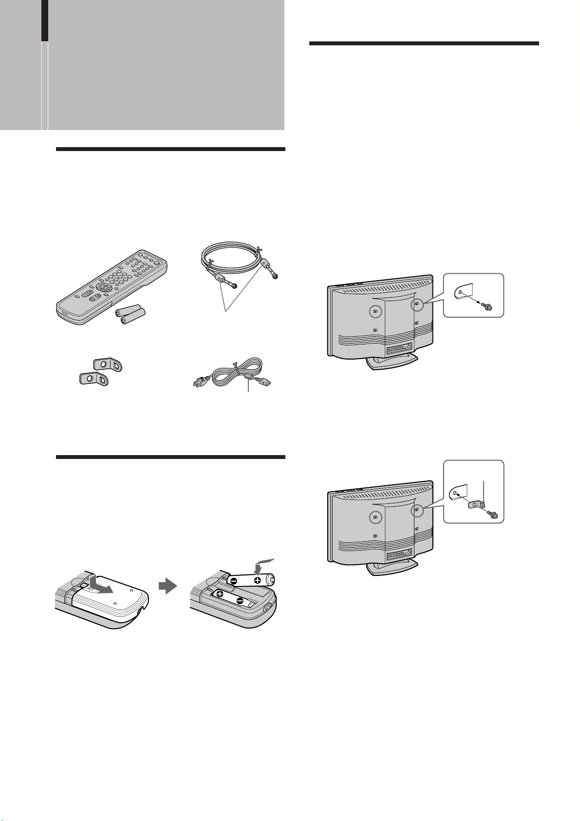
Unpacking
When you unpack this unit, make sure it includes the
following:
Remote control (1) and
size AA batteries (2)
75-ohm coaxial cable (1)
Do not remove
ferrite cores.
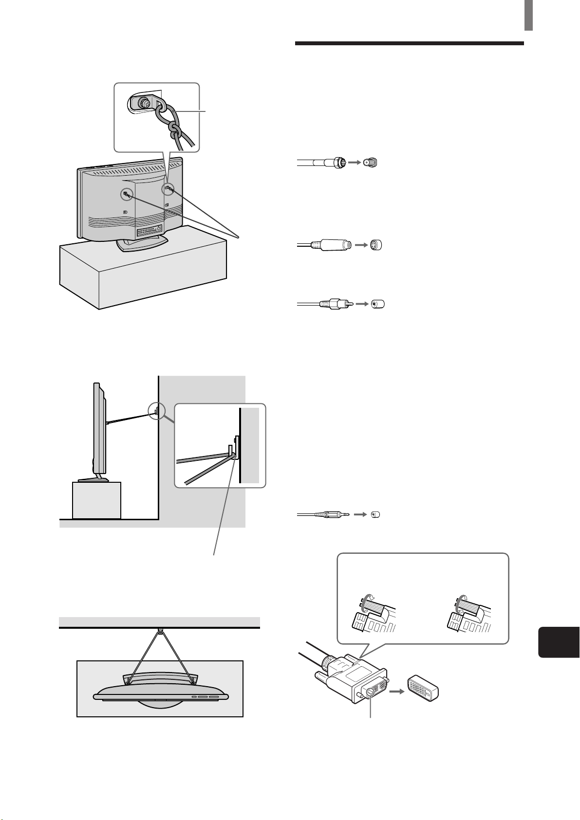
Preventing the TV from Falling Down
Attach the supplied brackets to the rear of the TV,
and pass a sturdy cord or chain and attach it to a wall
or pillar. Consult your dealer when attaching the
brackets, since the screws for the brackets also hold
the rear cabinet in a place.
1 Remove one of the screws attached at the rear of
the TV.
Note
Do not remove both screws at the same time as these screws
secure the rear cabinet. Never use the TV with the screws
removed.
Brackets (2)
Cleaning cloth (1)
Operating Instructions (1)
AC power cord (1)
Do not remove
ferrite core.
Inserting Batteries into the Remote Control
Insert two size AA batteries (supplied) by matching
the + and – on the batteries to the diagram inside the
remote control’s battery compartment.
2 Attach the supplied brackets with the screw.
Note
Be sure to use the screw that attaches the rear cabinet. A
different screw may damage the TV and result in electric
shock.
Bracket (supplied)
3 Repeat steps 1 and 2 to attach the other brackets.
Notes
• Remove the batteries to avoid damage from possible battery
leakage whenever you anticipate that the remote control will
not be used for an extended period.
• Handle the remote control with care. Avoid dropping it,
getting it wet, or placing it in direct sunlight, near a heater or
where the humidity is high.
• Your remote control can be programmed to operate most video
equipment. (See “Operating Video Equipment with Your TV
Remote Control” on page 33.)
6 (US)
Page 7
Installing and Connecting the TV
4 Attach a sturdy cord or chain securely to each
bracket on the rear of the TV.
Attach the cord
or chain
(not supplied)
securely.
5 Attach the cord or chain to a wall or pillar.
Side view
Connector Types
You may find it necessary to use some of the
following connector types during set up.
Supplied 75-ohm coaxial cable
Screw-on type
Screw into connection.
S VIDEO cable
High quality video cable for enhanced picture
quality
Align guides and push into
connection.
AUDIO/VIDEO cable
Push into connection.
VIDEO- Yellow
AUDIO (Left) - White
AUDIO (Right) - Red
Some DVD players are equipped with the following
three video connectors:
Top view
Screw a hook (not supplied) to
the wall or pillar securely.
Y - Green
B (CB, Cb or B–Y) - Blue
P
R (CR, Cr or R–Y) - Red
P
CONTROL S cable
CONTROL S connections are exclusive to Sony
equipment and allow greater control of all Sony
equipment.
Push into connection.
DVI-D single link cable
Loosen the screws
before connecting.
Tighten the screws
after connecting.
US
Align guides and push
into connection.
A
Note
The connector pin (A) of the DVI-D single link cable is “-” type.
“+” type cannot be used for this connection.
(US) 7
Page 8
Installing and Connecting the TV
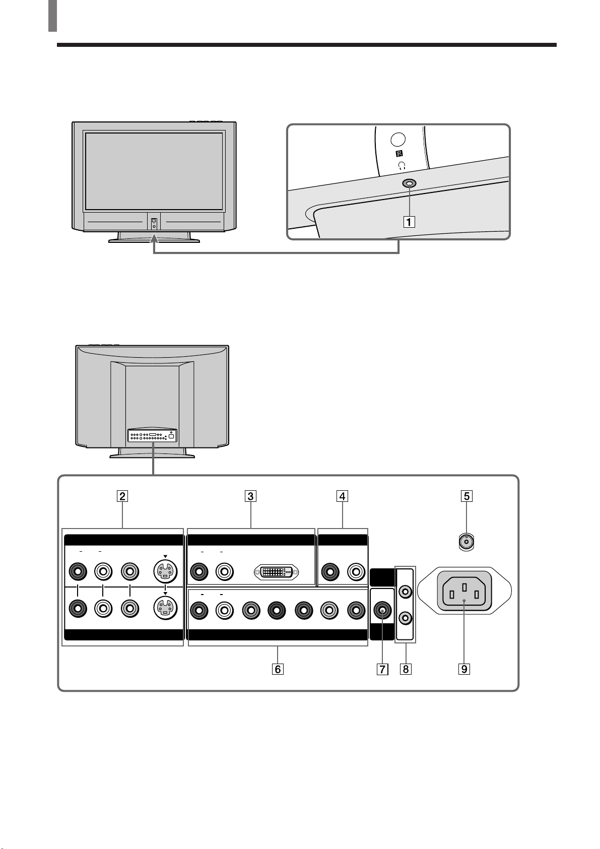
Identifying Front and Rear Connectors
TV front panel
Under the panel
Rear of TV
8 (US)
VIDEO IN 1 VIDEO IN 3
LR
AUDIO
VIDEO
S VIDEO
AUDIO
AUDIO
LR
LR
VIDEO IN 2
DVI-HDTV
PB/BY/G PR/R
VIDEO IN 4
AUDIO OUT
LR
HD VD
CONTROL
S
SUB
WOOFER
VHF/UHF
AC IN
IN
OUT
Page 9
1 Headphones jack
Connects to your headphones.
If your headphones do not match the jack, use a
suitable plug adaptor (not supplied).
2 VIDEO IN 1, 2 (pages 10 - 12, 15)
Connects to the output jacks of your VCR or
other video equipment.
3 VIDEO IN 3 (DVI-HDTV connector and
AUDIO (R/L) jacks) (page 16)
Accommodates a copy-protected digital
connection (HDCP*) to other devices (such as
digital set-top boxes) that have DVI-HDTV. The
DVI-HDTV input terminal is compliant with the
EIA-861 standard and is not intended for use
with personal computers. See the instruction
manual that came with your equipment for
details about connecting and using it with the
TV.
* High-bandwidth Digital Content Protection
4 AUDIO OUT (page 13)
Connects to the input jacks of your audio
equipment.
5 VHF/UHF (pages 10 - 12)
Connects to your VHF/UHF antenna or cable.
6 VIDEO IN 4
AUDIO (L/R) input jacks (pages 14, 17, 19):
Connects to the audio output jacks of your DVD
player or RGB equipment.
Y/G, P
B/B, PR/R, HD, VD input jacks:
Connecting a DVD player (page 14) or a Digital
TV Receiver (page 17)
Connect with component video connectors (Y/
C
B/CR, Y/B-Y/R-Y or Y/PB/PR) to the Y/G, PB/
B, P
R/R jacks on the TV.
Connecting an RGB equipment (page 19)
Connect the RGB equipment’s video/
synchronized signal output terminal to the Y/G,
P
B/B, PR/R, HD and VD jacks on the TV.
7 SUB WOOFER (page 18)
Connects to the input jack of your sub woofer.
8 CONTROL S IN/OUT
To control other Sony equipment with the TV’s
remote control,** connect the CONTROL
S IN jack of the equipment to the CONTROL S
OUT jack of the TV with the CONTROL S
cable.
To control the TV with a remote control for
another Sony equipment, connect the CONTROL
S OUT jack of the equipment to the CONTROL
S IN jack on the TV with the CONTROL S
cable.
** Only when the TV is turned on, or the STANDBY/
SLEEP indicator lights up in red. When the TV is turned
off (the STANDBY/SLEEP indicator goes off), you
cannot use this function.
9 AC IN
Connects the supplied AC power cord.
Installing and Connecting the TV
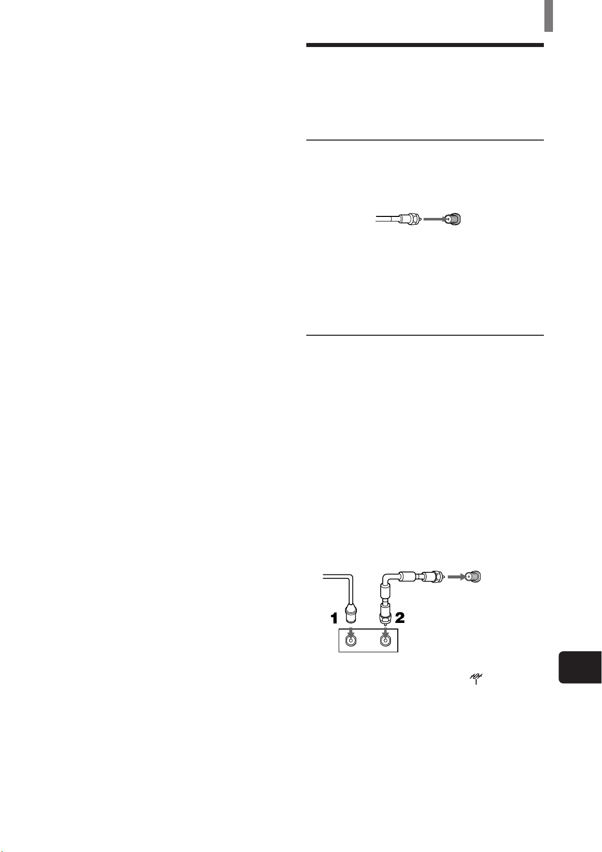
Basic Connections (Connecting Cable TV or Antenna)
Connecting directly to cable or an antenna
VHF only or VHF/UHF or cable
75-ohm coaxial
cable (supplied)
VHF/UHF
Note
It is strongly recommended to connect the antenna using a 75ohm coaxial cable to get optimum picture quality. A 300-ohm
twin lead cable can be easily affected by radio noise and the like,
resulting in signal deterioration. If you use a 300-ohm twin lead
cable, keep it away as far as possible from the TV.
Cable box connections
Use this hookup if:
• You subscribe to a cable TV system that uses
scrambled or encoded signals requiring a cable
box to view all channels, and
• You do not intend to hook up any other audio or
video equipment to your TV.
1 Connect the coaxial connector from your cable
service to the cable box’s IN jack.
2 Using the supplied 75-ohm coaxial cable,
connect the cable box’s OUT jack to the TV’s
VHF/UHF jack.
75-ohm coaxial
Cable
IN
Cable box
Also, set “Cable” to “On” in the
menu (See page 21).
Tips
• Your Sony remote control can be programmed to operate your
cable box. (See “Programming the remote control” on page
33).
• To change channels using the cable box, set your TV to
channel 3 or 4 depending on the cable box channel output.
cable (supplied)
VHF/UHF
OUT
Rear of TV
Rear of TV
(TV Setup)
US
(US) 9
Page 10
Installing and Connecting the TV
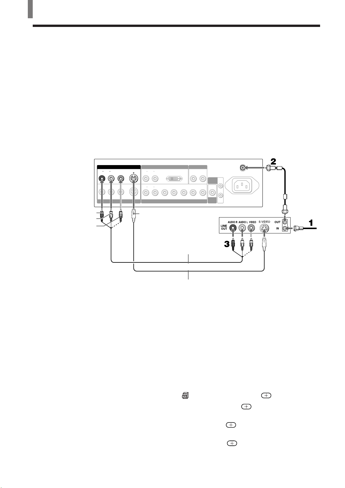
Connecting a VCR and Cable
Use this hookup if:
• You have cable TV that does not require a cable box.
Disconnect all power sources before making any connections.
1 Connect the cable TV cable to the VCR’s IN jack.
2 Using the supplied 75-ohm coaxial cable, connect the VCR’s OUT jack
to the TV’s VHF/UHF jack.
3 Using AUDIO and S VIDEO cables, connect the VCR’s Audio and S Video
OUT jacks to the TV’s AUDIO and S VIDEO IN jacks.
Rear of TV
AUDIO-R (red)
AUDIO-L (white)
VIDEO (yellow)
VIDEO IN 1 VIDEO IN 3
LR
AUDIO
VIDEO
S VIDEO
VIDEO IN 2
LR
AUDIO
LR
AUDIO
S VIDEO
Tip
If your VCR is not equipped with S VIDEO, use a VIDEO cable (yellow) instead of the S
VIDEO cable.
AUDIO OUT
HD VD
LR
CONTROL
S
SUB
WOOFER
OUT
VCR
DVI-HDTV
PB/BY/G PR/R
VIDEO IN 4
VMC-810S/820S
(not supplied)
YC-15V/30V (not supplied)
VHF/UHF
AC IN
IN
75-ohm
coaxial cable
(supplied)
Cable
10 (US)
When connecting both VIDEO OUT and S VIDEO OUT
You can select which jack the TV receives the input signal from on the menu
screen. You can set it for each video input (VIDEO IN 1 and VIDEO IN 2)
separately. The TV is factory set to receive S VIDEO input signals.
1 Press TV/VIDEO repeatedly until the desired video input appears.
2 Press MENU.
3 Press V/v to select (Custom Setup), then press .
4 Press V/v to select “Auto YC,” then press .
5 To watch the pictures input from the S VIDEO input jack:
Press V/v to select “On,” then press
To watch the picture input from the VIDEO input jack:
Press V/v to select “Off,” then press
.
.
6 Press MENU to exit the menu screen.
Page 11
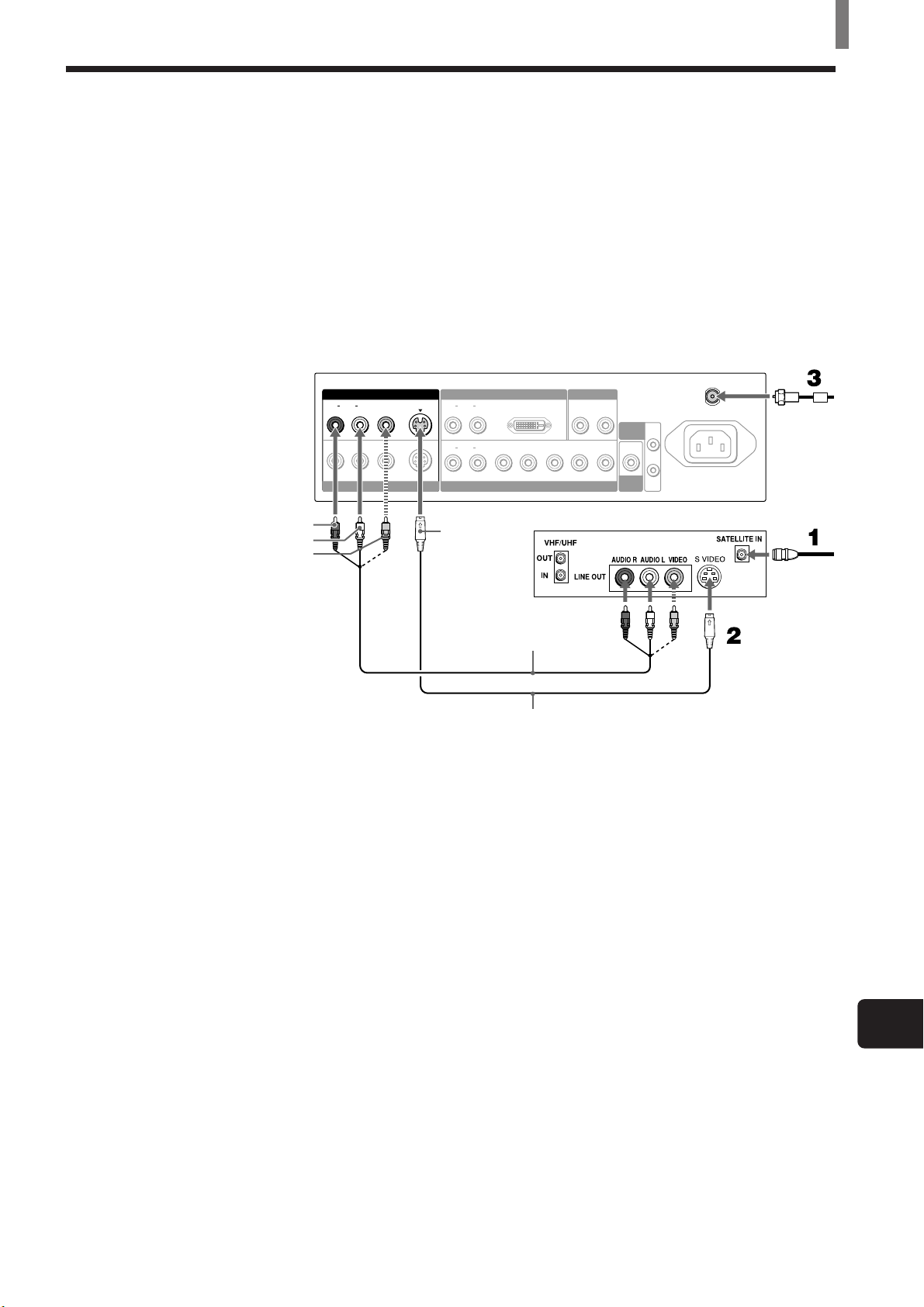
Connecting a Satellite Receiver
Disconnect all power sources before making any connections.
1 Connect the satellite antenna cable to the satellite receiver’s SATELLITE
IN jack.
2 Using AUDIO and S VIDEO cables, connect the satellite receiver’s AUDIO
and S VIDEO OUT jacks to the TV’s AUDIO and S VIDEO IN jacks.
3 Connect the supplied 75-ohm coaxial cable from your cable or antenna to the
TV’s VHF/UHF jack.
Rear of TV
VIDEO IN 1 VIDEO IN 3
LR
AUDIO
VIDEO
S VIDEO
VIDEO IN 2
AUDIO
AUDIO
LR
LR
DVI-HDTV
VIDEO IN 4
PB/BY/G PR/R
AUDIO OUT
LR
HD VD
Installing and Connecting the TV
VHF/UHF
CONTROL
S
SUB
WOOFER
AC IN
IN
OUT
75-ohm
coaxial
cable
(supplied)
AUDIO-R (red)
AUDIO-L (white)
VIDEO (yellow)
S VIDEO
Satellite receiver
Satellite
antenna
cable
VMC-810S/820S (not supplied)
YC-15V/30V (not supplied)
Tip
If your satellite receiver is not equipped with S VIDEO, use a VIDEO cable (yellow) instead
of the S VIDEO cable.
(US) 11
US
Page 12
Installing and Connecting the TV
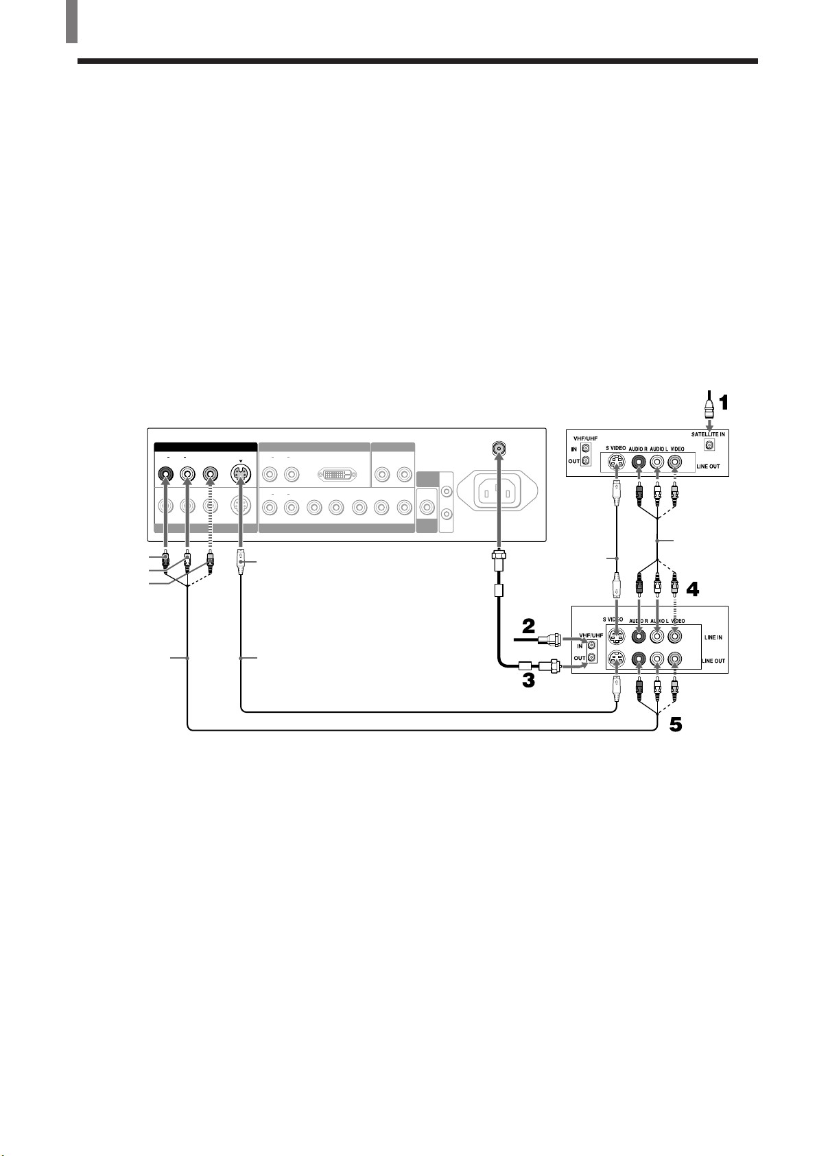
Connecting a Satellite Receiver with a VCR
Disconnect all power sources before making any connections.
1 Connect the satellite antenna cable to the satellite receiver’s SATELLITE
IN jack.
2 Connect the CATV cable to the VCR’s VHF/UHF IN jack.
3 Using the supplied 75-ohm coaxial cable, connect the VCR’s OUT jack
to the TV’s VHF/UHF jack.
4 Using AUDIO and S VIDEO cables, connect the satellite receiver’s
AUDIO and S VIDEO OUT jacks to the VCR’s AUDIO and S VIDEO
IN jacks.
5 Using AUDIO and S VIDEO cables, connect the VCR’s AUDIO and S
VIDEO OUT jacks to the TV’s AUDIO and S VIDEO IN jacks.
AUDIO-R (red)
AUDIO-L (white)
VIDEO (yellow)
Rear of TV
AUDIO
VIDEO IN 1 VIDEO IN 3
LR
VIDEO
S VIDEO
VIDEO IN 2
AUDIO
AUDIO
LR
LR
VIDEO IN 4
S VIDEO
DVI-HDTV
PB/BY/G PR/R
AUDIO OUT
LR
HD VD
CONTROL
IN
S
OUT
SUB
WOOFER
75-ohm
coaxial cable
(supplied)
VHF/UHF
AC IN
Satellite receiver
YC-15V/30V
(not supplied)
VCR
Satellite
antenna
cable
VMC810S/820S
(not supplied)
VMC-810S/820S
(not supplied)
YC-15V/30V (not supplied)
Cable
Tips
• Be sure your VCR’s video input is set correctly. Consult your VCR’s operating manual for
instructions.
• Use TV/VIDEO on the remote to select VIDEO IN 1 to watch satellite TV or the VCR
(your VCR must be turned on). Use 0-9 and ENTER or CH +/– on the remote to watch
cable TV.
• If your VCR or satellite receiver is not equipped with S VIDEO, use a VIDEO cable
(yellow) instead of the S VIDEO cable.
12 (US)
Page 13
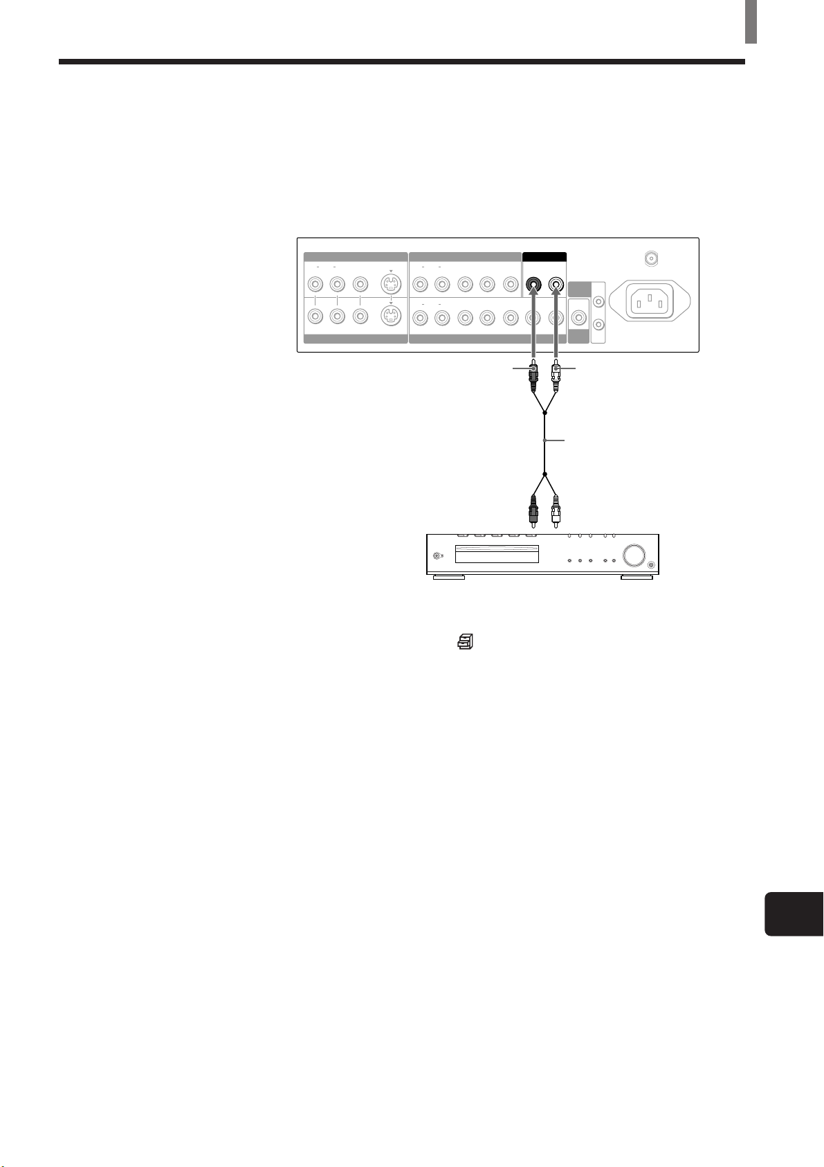
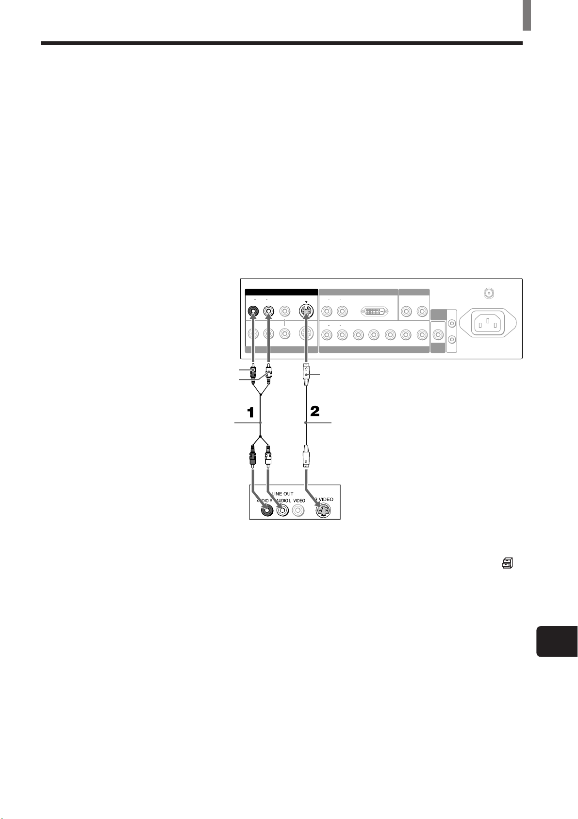
Connecting an Audio Receiver
Disconnect all power sources before making any connections.
Using an AUDIO cable, connect the TV’s AUDIO OUT jacks to the audio
receiver’s AUDIO IN jacks.
Rear of TV
VIDEO IN 1 COMPONENT VIDEO IN 1
LR
AUDIO
VIDEO
S VIDEO
VIDEO IN 2
LR
AUDIO
LR
AUDIO
COMPONENT VIDEO IN 2 / RGB IN
AUDIO OUT
PBYP
R
PB/BY/G PR/R
HD VD
Installing and Connecting the TV
VHF/UHF
LR
CONTROL
S
SUB
WOOFER
IN
OUT
AC IN
AUDIO-R (red)
AUDIO-L
(white)
RK-74A
(not supplied)
Audio
input
Audio reciever (Compact
AV system DAV-C990, etc)
When using your audio system speakers
Set “Speaker” to “Off” on the (Custom Setup) menu. The TV’s sound is
not output through the TV’s speakers.
Tip
The sound signal of an equipment connected to the VIDEO IN 4 jacks is also output through
the AUDIO OUT jacks. Note that the video signal is not output.
Note
Even though you change the TV’s volume or other sound settings, the sound of your audio
system does not change.
(US) 13
US
Page 14
Installing and Connecting the TV
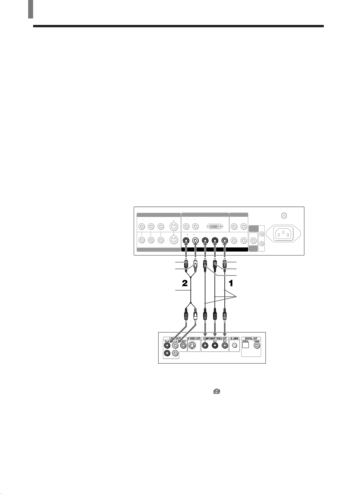
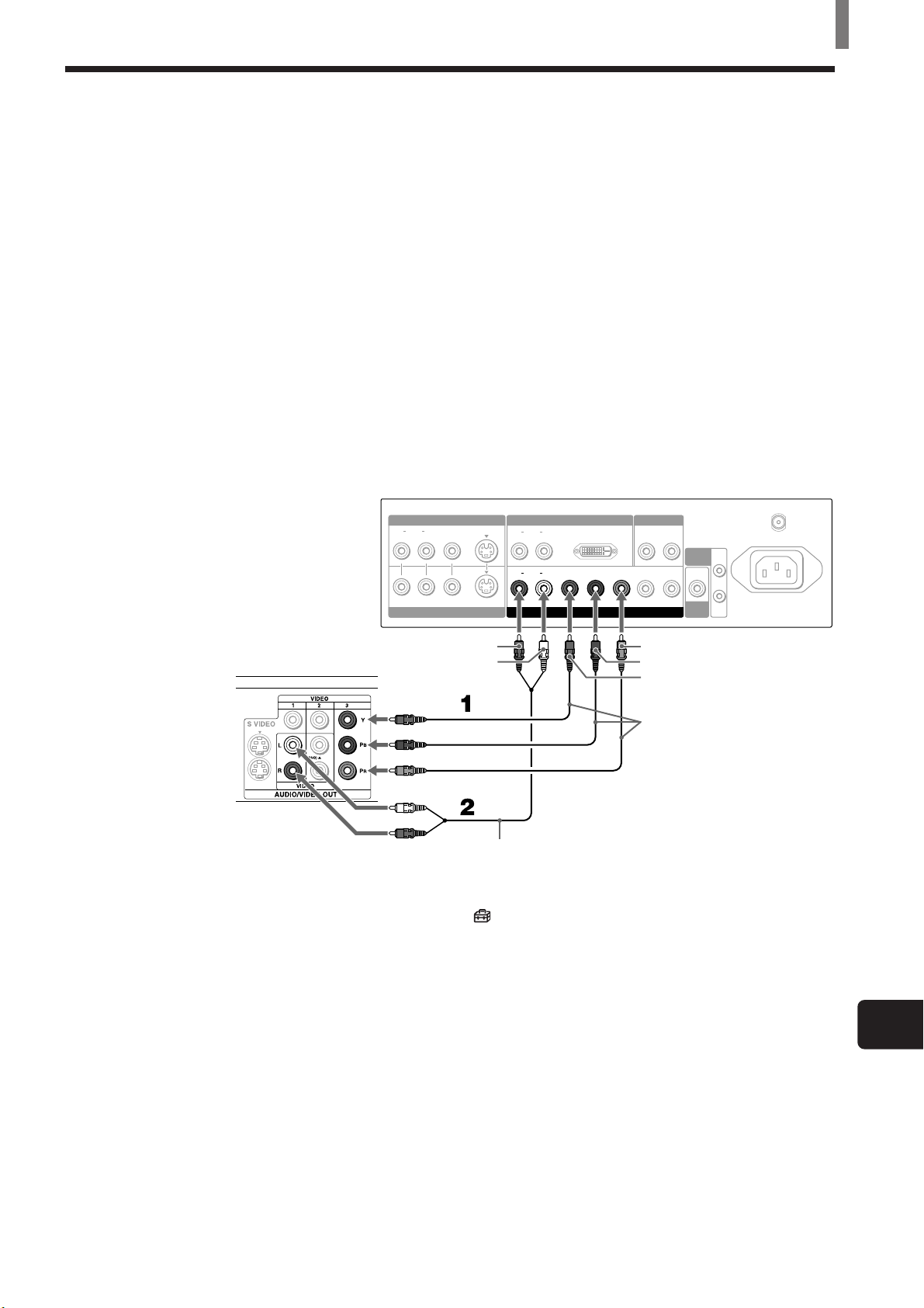
Connecting a DVD Player with Component Video Connectors
This is the preferred hookup to use if:
• Your DVD player has component (Y, B-Y, R-Y) jacks.
Disconnect all power sources before making any connections.
1 Using three separate component video cables, connect the DVD player’s
Y, B-Y and R-Y jacks to the Y/G, P
the VIDEO IN 4 connections.
Tip
The Y, B-Y and R-Y jacks on your DVD player are sometimes labeled as Y, CB and CR,
or Y, PB and PR. If so, connect the cables to the matching colors.
2 Using an AUDIO cable, connect the DVD player’s AUDIO OUT jacks to
the TV’s AUDIO IN jacks. Be sure to use the same row of inputs that
you used for the video connection.
B/B and PR/R jacks on the TV. Use
Rear of TV
VIDEO IN 1
LR
AUDIO
VIDEO
VIDEO IN 2
AUDIO-R (red)
AUDIO-L (white)
RK-74A (not supplied)
DVD player
S VIDEO
AUDIO
AUDIO
VIDEO IN 3
LR
LR
DVI-HDTV
B
/BY/G PR/R
P
VIDEO IN 4
AUDIO OUT
LR
CONTROL
IN
HD VD
S
OUT
SUB
WOOFER
P
R/R
P
B/B
Y/G
VMC-10HG (not supplied)
VHF/UHF
AC IN
14 (US)
Note
Set “Video 4 Mode” to “Y/PB/ PR” in the (Initial Setup) menu (see page 32).
Tips
• To take advantage of the Wide Screen Modes, set the TV’s aspect ratio to 16:9 on your
DVD player. For details, refer to the operating instructions supplied with your DVD player.
• Some DVD players are equipped with the three component video connectorsP: Y-Green, P
(CB, Cb or B-Y) -Blue and PR (CR, Cr or R-Y) -Red.
B
Page 15
Installing and Connecting the TV
Connecting a DVD Player with A/V Connectors
Use this hookup if:
• Your DVD player does not have component (Y, P
B, PR) jacks.
Tip
If your DVD player has video component output connectors, for best picture quality, use the
connection described on page 14.
Disconnect all power sources before making any connections.
1 Using an AUDIO cable, connect the DVD player’s AUDIO OUT jacks to
the TV’s AUDIO IN jacks.
2 Using an S VIDEO cable, connect the DVD player’s S VIDEO jack to
the TV’s S VIDEO jack.
Rear of TV
VHF/UHF
IN
AUDIO-R (red)
AUDIO-L (white)
VIDEO IN 1 VIDEO IN 3
LR
AUDIO
VIDEO
S VIDEO
VIDEO IN 2
AUDIO
AUDIO
LR
LR
S VIDEO
DVI-HDTV
PB/BY/G PR/R
VIDEO IN 4
AUDIO OUT
LR
HD VD
CONTROL
S
SUB
WOOFER
OUT
AC IN
RK-74A
(not supplied)
YC-15V/30V
(not supplied)
DVD player
Note
To watch the pictures input from the S VIDEO input jack, set “Auto YC” to “On” in the
(Custom Setup) menu (see page 10).
Tips
• To take advantage of the Wide Screen Modes, set the TV’s aspect ratio to 16:9 on your
DVD player. For details, refer to the operating instructions supplied with your DVD player.
• Use TV/VIDEO on the remote to switch between the VCR and DVD player inputs. Use 0-9
and ENTER or CH +/– on the remote to watch cable TV.
• If your DVD player is not equipped with S VIDEO, use a VIDEO cable (yellow) instead of
the S VIDEO cable.
US
(US) 15
Page 16
Installing and Connecting the TV
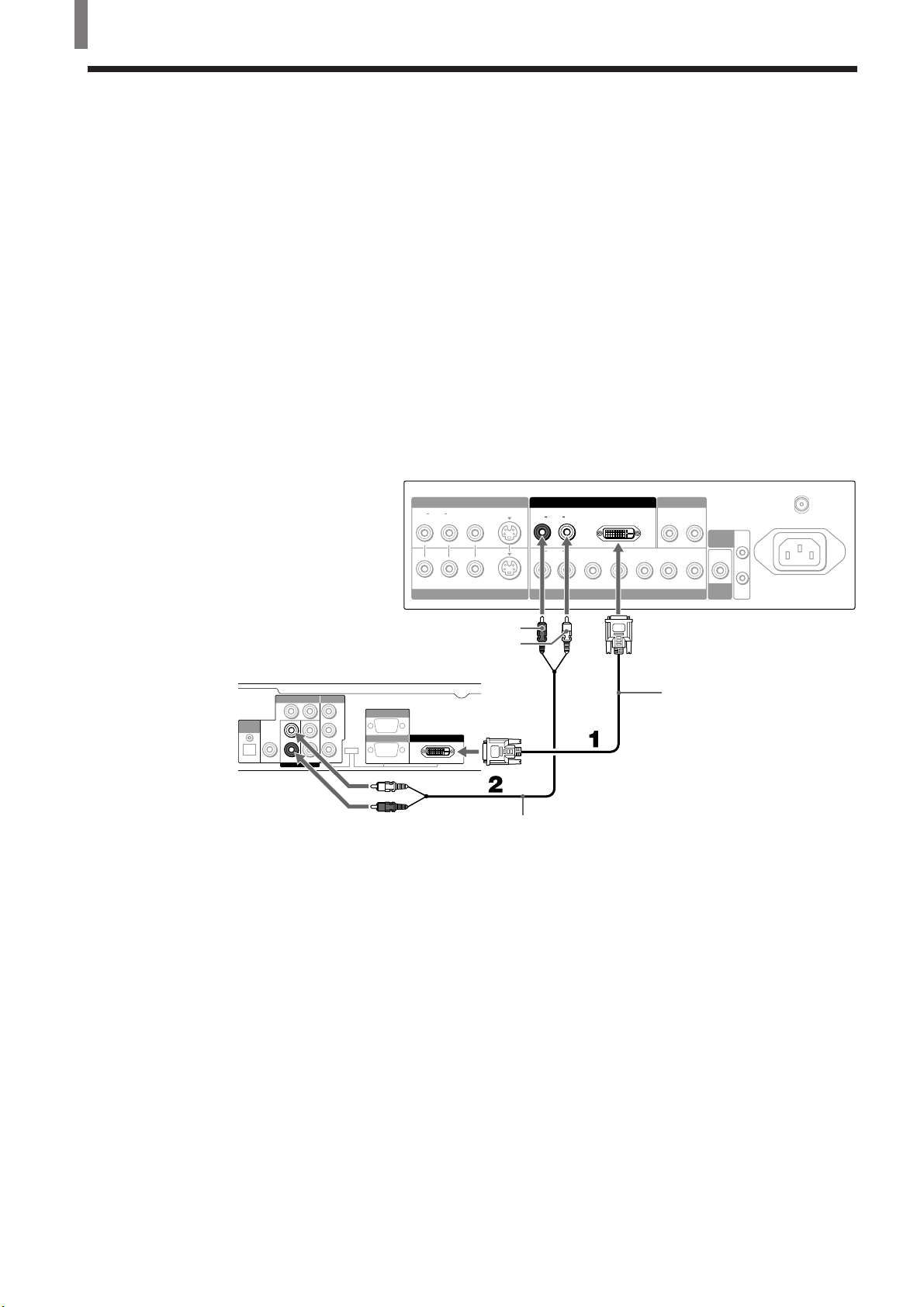
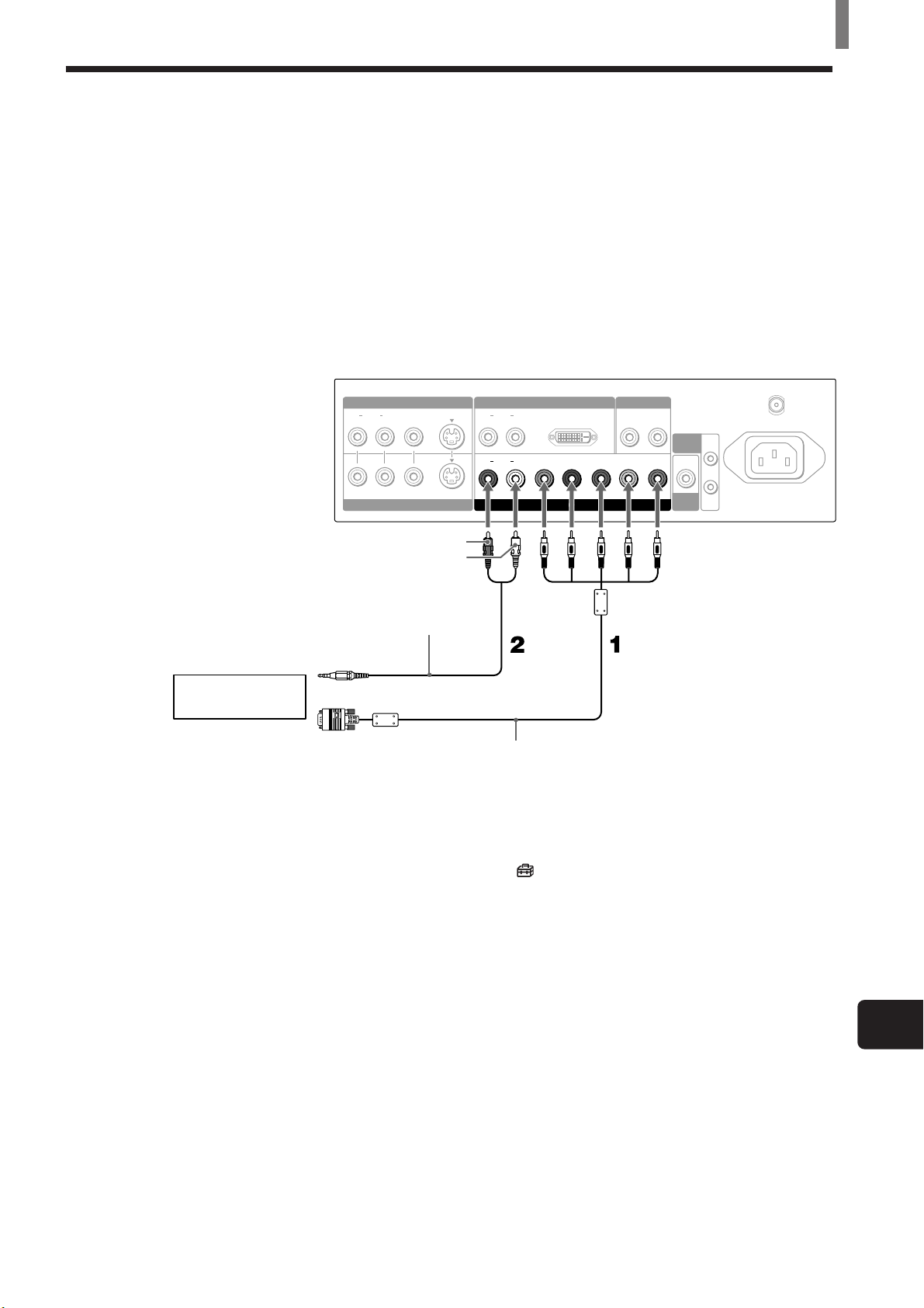
Connecting a Digital Satellite Receiver
Disconnect all power sources before making any connections.
1 Using a DVI-D singe link cable, connect the Digital Satellite Receiver’s
DVI-HDTV OUT connector to the TV’s DVI-HDTV IN connector.
Note
DVI-HDTV connection or component video (Y, PB, PR) connection is necessary to view 480p,
720p, and 1080i formats. Note that this TV displays all format types of picture in a resolution
of 852 dots × 1024 lines (KE-32TS2U), or 1024 × 1024 (KE-42TS2U).
2 Using an AUDIO cable, connect the Digital Satellite Receiver’s Audio
OUT jacks to the TV’s AUDIO IN jacks.
Note
The DVI-HDTV connector does not provide audio, so audio cables must be connected to
provide sound.
Rear of TV
VIDEO IN 1 VIDEO IN 3
LR
AUDIO
VIDEO
VIDEO IN 2
S VIDEO
AUDIO
AUDIO
LR
LR
DVI-HDTV
PB/BY/G PR/R
VIDEO IN 4
AUDIO OUT
LR
HD VD
CONTROL
S
SUB
WOOFER
VHF/UHF
AC IN
IN
OUT
Digital Satellite Receiver
(SAT-HD200)
VIDEO OUT
VIDEO OUT
(1080i/720p/480p)
(480i)
1
2
AUDIO OUT
Y
B
P
TYPE
PR
R2
OPTICAL
AUDIO
OUT
L1 L2
R1
S. VIDEOOPTICAL
AUDIO-R (red)
AUDIO-L (white)
AUTHORIZED
SERVICES ONLY
RGB OUT DVI-HDTV OUT
(1080i/720p/480p) (1080i/720p/480p)
DVI-D single link cable
(not supplied)
RK-74A (not supplied)
16 (US)
Page 17
Connecting a Digital TV Receiver
Disconnect all power sources before making any connections.
1 Using three separate component video cables, connect the Digital TV
Set-top box’s Y, P
TV. Use the VIDEO IN 4 connection.
Note
DVI-HDTV connection or component video (Y, PB, PR) connection is necessary to view 480p,
720p, and 1080i formats. Note that this TV displays all format types of picture in a resolution
of 852 dots × 1024 lines (KE-32TS2U), or 1024 × 1024 (KE-42TS2U).
2 Using an AUDIO cable, connect the Digital TV Set-top box’s Audio
OUT jacks to the TV’s AUDIO IN jacks.
Note
The Y, PB and PR jacks do not provide audio, so audio cables must be connected to provide
sound.
Rear of TV
AUDIO
B and PR jacks to the Y/G, PB/B and PR/R jacks on the
VIDEO IN 1 VIDEO IN 3
LR
VIDEO
S VIDEO
VIDEO IN 2
AUDIO
AUDIO
LR
LR
DVI-HDTV
PB/BY/G PR/R
VIDEO IN 4
Installing and Connecting the TV
AUDIO OUT
LR
HD VD
CONTROL
S
SUB
WOOFER
OUT
VHF/UHF
AC IN
IN
Digital TV Set-top box
Note
Select “Video 4 Mode” in the (Initial Setup) menu, then select “Y/PB/PR” or “RGB”
depending on the Digital TV Set-top box you connect (see page 32).
AUDIO-R (red)
AUDIO-L (white)
RK-74A (not supplied)
P
R/R
B/B
P
Y/G
VMC-10HG (not supplied)
US
(US) 17
Page 18
Installing and Connecting the TV
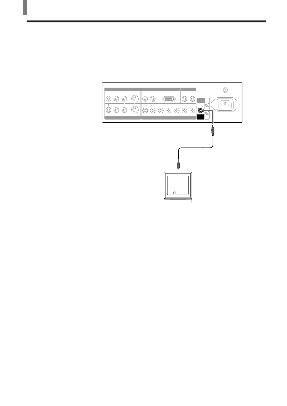
Connecting a Sub Woofer
Disconnect all power sources before making any connections.
Using a monaural audio cable, connect the TV’s SUB WOOFER jack to the
sub woofer’s input jack.
Rear of TV
VIDEO IN 1 VIDEO IN 3
LR
AUDIO
VIDEO
S VIDEO
VIDEO IN 2
AUDIO
AUDIO
LR
LR
Sub woofer input
Sub woofer
(SA-WD200 etc.)
DVI-HDTV
PB/BY/G PR/R
VIDEO IN 4
AUDIO OUT
LR
HD VD
VHF/UHF
CONTROL
S
SUB
WOOFER
IN
OUT
AC IN
SUB
WOOFER
Monaural audio cable
(not supplied)
18 (US)
Page 19
Connecting an RGB Equipment
Disconnect all power sources before making any connections.
1 Using an RGB cable, connect the RGB equipment’s video/synchronized
signal output terminal to the Y/G, P
TV. Use the VIDEO IN 4 connections.
2 Using an AUDIO cable, connect the RGB equipment’s AUDIO OUT
jacks to the TV’s AUDIO IN jacks. Be sure to use the same row of inputs
that you used for the video connection.
Rear of TV
Installing and Connecting the TV
B/B, PR/R, HD, and VD jacks on the
RGB equipment
VIDEO IN 1 VIDEO IN 3
LR
AUDIO
VIDEO IN 2
AUDIO-R (red)
AUDIO-L (white)
RK-G129
To the audio
(not supplied)
output jacks
To the video/
synchronized signal
output terminal
VIDEO
S VIDEO
LR
AUDIO
LR
AUDIO
VIDEO IN 4
SMF-403
(not supplied)
DVI-HDTV
PB/BY/G PR/R
AUDIO OUT
LR
HD VD
CONTROL
S
SUB
WOOFER
VHF/UHF
AC IN
IN
OUT
Note
Set “Video 4 Mode” to “RGB” in the (Initial Setup) menu (see page 32).
US
(US) 19
Page 20
Installing and Connecting the TV
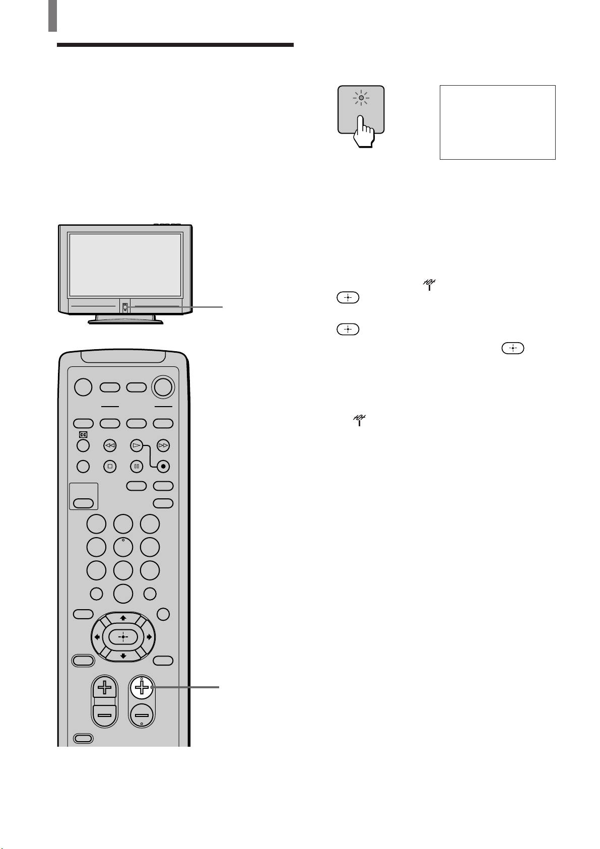
Setting the Channels
After you finish connecting your TV, you can run
Auto Program to set up your channels. The Auto
Program screen appears when you turn your TV on
for the first time after installing it.
To change or skip channels, see page 21.
Note
The Auto Program feature does not apply for an installation that
uses a cable box for all channels.
1
1 Press Power on the front panel of your TV. The
Auto Setup menu appears.
A uto Setup
[
[
POWER
,
A uto Program:
Exit
First please connect
cable antenna/
[
CH+
CH–
[
2 Press CH+ on the remote control or on the front
panel of your TV to perform Auto Program.
To perform Auto Program again
1 Press MENU.
2 Press V/v to select (TV Setup), then press
.
3 Press V/v to select “Auto Program,” then press
.
MUTING POWER
VCR/DVD
SYSTEM
OFF
SLEEP
PICTURE
MODE
FUNCTION
VCR/DVD
SAT/CABLE
SAT/CABLE
WIDE MODE DISPLAY
TV
TV
TV/VIDEO
123
456
7809
JUMP
FAVORITES
TV/SAT
ENTER
MTS/SAP
GUIDE
4 Press V/v to select “OK,” then press .
“Auto-Channel Set” appears and the TV starts
scanning and presetting channels automatically.
When all the receivable channels are stored, the
lowest numbered channel will be displayed, then
the
(TV Setup) menu appears.
5 Press MENU to exit the menu screen.
To cancel Auto Program
While “Auto-Channel Set” appears in step 4, press
MENU on the remote.
20 (US)
POWER
SAVING
VOL CH
CODE SET
MENU
2
Page 21
Installing and Connecting the TV
TV Set up
Channe l
Channe l Sk i p Add/
,,,to to
set
select
ENTER
1Skip
Skip
Add
Skip
Skip
Skip
Add
Add
:
2
:
3
:
4
:
5
:
6
:
7
:
8
:
+/–
To watch CATV channels
You have to subscribe to a cable TV company. Note
that cable TV cannot be received in some areas. This
TV receives 1-125 cable TV channels. For details on
cable TV subscription, consult your nearest cable TV
company.
1 Press MENU.
2 Press V/v to select (TV Setup), then press
.
3 Press V/v to select “Cable,” then press .
4 Press V/v to select “On,” then press .
5 Perform steps 3 and 4 on page 20.
Note
You cannot receive and set the CATV channels and UHF
channels at the same time.
When you have a cable box or satellite receiver
connected
The Channel Fix feature is useful when you have a
cable box or satellite receiver connected. For details,
see page 53.
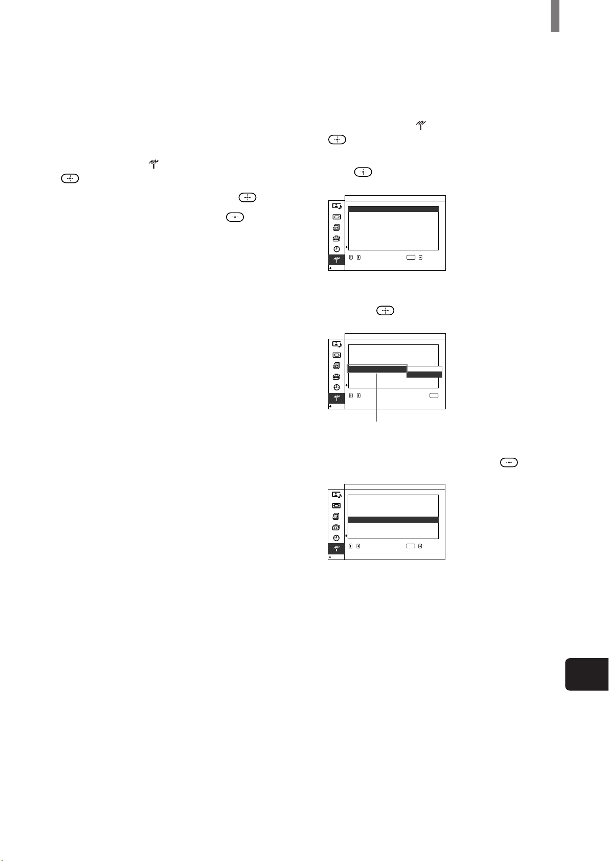
To skip channels
You can skip unnecessary channels when selecting
channels using the CH +/– buttons.
1 Press MENU.
2 Press V/v to select (TV Setup), then press
.
3 Press V/v to select “Channel Skip/Add,” then
press
.
TV Set up
Channe l Sk i p Add/
Channe l
+/–
:
1 Ski p
:
Skip
2
:
Add
3
:
Skip
4
:
Add
5
:
6
Skip
:
7
Add
:
8
Add
select
ENTER
,,,to to
set
4 Press V/v to select the channel you want to skip,
then press
TV Set up
Channe l Sk i p Add/
Channe l
to return
.
:
1 Ski p
:
Skip
2
:
Add
3
:
Skip
4
:
+/–
Add
5
Skip
:
6
Add
:
7
Add
:
8
Add
select,,to
select press
ENTER
Example: Select this
to skip channel 5.
5 Press V/v to select “Skip,” then press .
If you want to re-enter the skipped channel,
select “Add.”
6 Press MENU to exit the menu screen.
US
(US) 21
Page 22
Installing and Connecting the TV
Selecting the On-screen Menu Language
You can select the language to be displayed in all
menu.
MUTING POWER
VCR/DVD
SYSTEM
OFF
SLEEP
PICTURE
MODE
FUNCTION
VCR/DVD
123
456
SAT/CABLE
SAT/CABLE
WIDE MODE DISPLAY
TV
TV
TV/VIDEO
1 Press MENU.
Picture/Sound Control
MENU
Picture Mode
Adjust Picture
Adjust
Sound
:
Liv.Rm.
,
select
:
:
:
:
ENTER
On
/Off
Y/PB/PR
,,,to to
enter adj . menu
2 Press V/v to select (Initial Setup), then press
.
Init ial Setup
L anguage Engl i s h
Color Sy stem
MENU
Function
Vi deo
4Mode
,
select
ENTER
:
:
Francais
:
Español
:
Y/PB/PR
,,,to to
set
3 Press V/v to select “Language,” then press .
Init ial Setup
L anguage Eng l i s h
Color Sy stem
MENU
Function
Vi deo
4Mode
,
7809
JUMP
FAVORITES
TV/SAT
POWER
SAVING
VOL CH
CODE SET
ENTER
MTS/SAP
GUIDE
MENU
2 - 4
1, 5
select,,to
select press
to return
ENTER
4 Press V/v to select your preferred language, then
press
.
init ialRéglage
MENU
:
Francais
:
:
Mar/arr.
:
Y/PB/PR
L angue
Sy st. couleur
Fonction
Vidéo 4Mode
,
ENTER
pour
sélectionner
pour régler
5 Press MENU to exit the menu screen.
,,
22 (US)
Page 23
Watching the TV
123
456
7809
ENTER
VOL
Watching the TV
Watching the TV
STANDBY/
SLEEP
MUTING
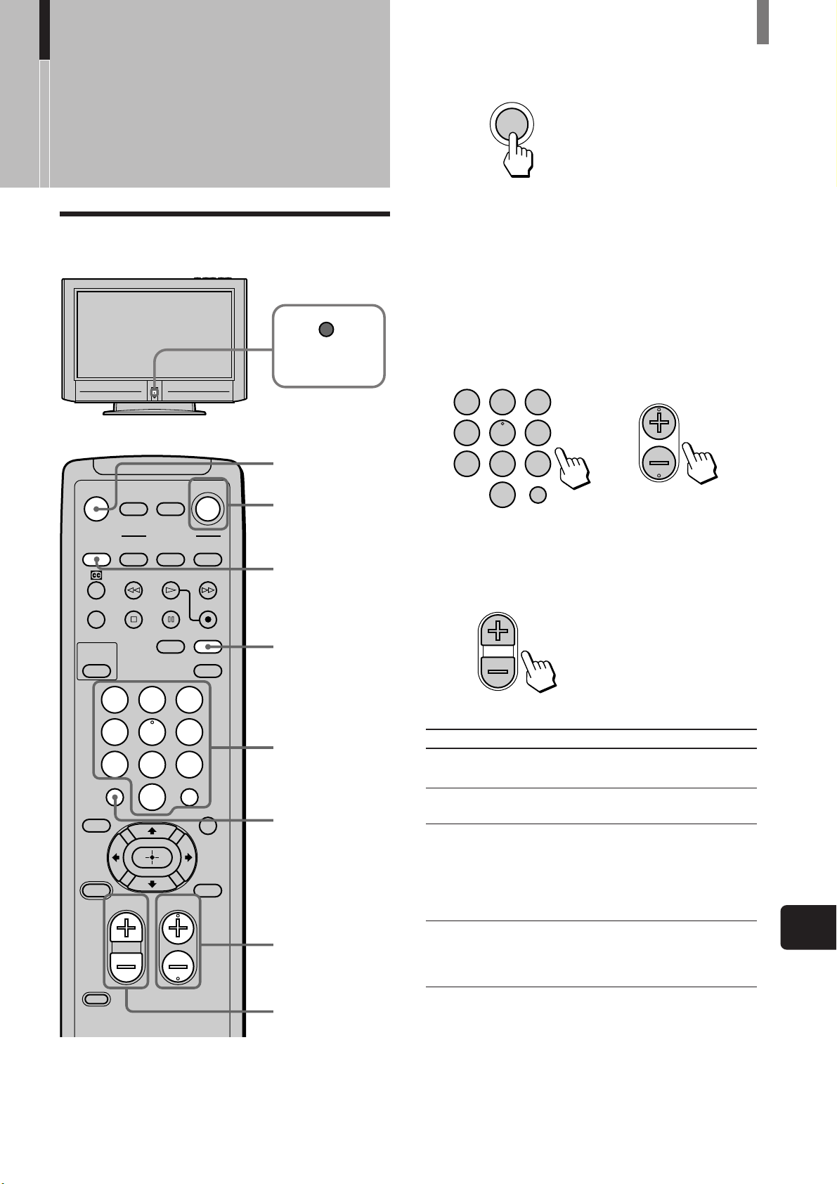
1 Press POWER on the remote.
POWER
TV
Tip
When the STANDBY/SLEEP indicator goes off, press
POWER on the TV.
2 Select the desired channel using the 0-9 and
ENTER buttons.
Press 0-9 to select a channel, the channel
changes after 2 seconds. Press ENTER to select
immediately.
Use the CH +/– buttons to scan through the
channels.
CH
or
MUTING POWER
SYSTEM
OFF
SLEEP
PICTURE
MODE
FAVORITES
TV/SAT
POWER
SAVING
CODE SET
VCR/DVD
SAT/CABLE
FUNCTION
SAT/CABLE
VCR/DVD
WIDE MODE DISPLAY
TV/VIDEO
123
456
7809
JUMP
VOL CH
ENTER
MTS/SAP
GUIDE
MENU
TV
TV
1
SYSTEM OFF
DISPLAY
2
JUMP
2
3
Tip
When you press and hold CH + or – the channel number
will change rapidly.
3 Adjust the volume using the VOL +/– buttons.
Other button operations
Press To
MUTING
SYSTEM OFF
DISPLAY
JUMP
Tips
• While the STANDBY/SLEEP indicator is lit, the TV turns on
automatically if you press the 0-9 and ENTER buttons or CH
+/– buttons on the remote.
• You can adjust the volume by referring to the value beside the
volume indication (on screen).
mute the sound. Press again or press
VOL + to restore sound.
turn off the TV and all other Sony
equipment.
display the current channel number.
Press again to turn display off.
The channel display will automatically
disappear after a few minutes.
To display the channel again, press
again.
jump back and forth between two
channels. The TV alternates between the
current channel and the last channel
selected using the 0-9 buttons.
(Continued)
US
(US) 23
Page 24
Watching the TV
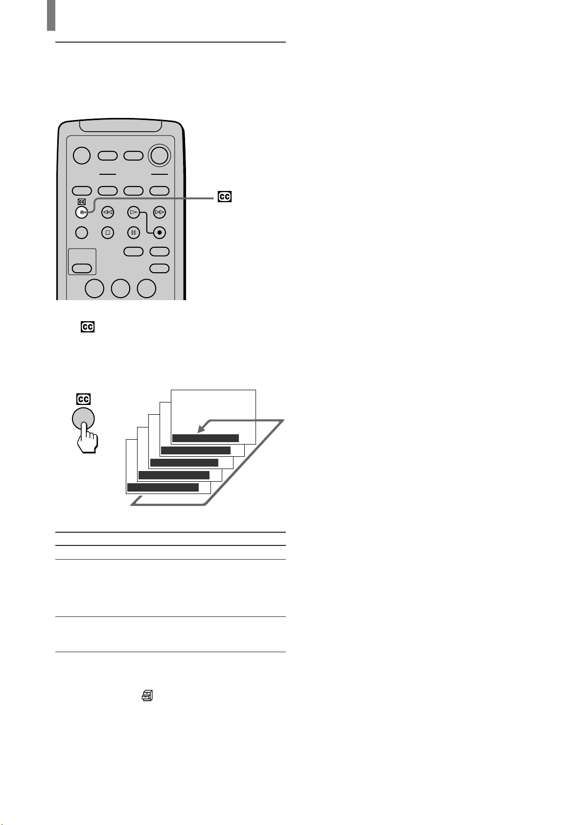
Watching with closed caption
You can display Caption Vision if the broadcaster
offers this service.
MUTING POWER
VCR/DVD
SAT/CABLE
TV
SYSTEM
OFF
SLEEP
PICTURE
MODE
FUNCTION
VCR/DVD
WIDE MODE DISPLAY
SAT/CABLE
TV
TV/VIDEO
123
Press repeatedly until the desired Caption Vision
appears.
Each time you press the button, Caption Vision
changes as follows:
,
Caption Vision : Off
Caption Vision : CC1
Caption Vision : CC2
Caption Vision : Text1
Caption Vision : Text2
Select
Off
CC1 (Capture 1),
CC2 (Capture 2)
Text1, Text2
To
turn off Caption Vision.
display a printed version of the
dialogue or sound effects of a
program. (The mode should be
set to CC1 (Capture 1) for
most programs.)
display network/station
information presented using
either half or the whole screen.
Tip
You can select Caption Vision on the menu screen. Select
“Caption Vision” in the
the desired Caption Vision.
(Custom Setup) menu, then select
24 (US)
Page 25
Enjoying High-quality Pictures and Sounds
To enjoy high-quality pictures and sound, refer to the
following and adjust the picture and audio options to
best suit the program you are watching.
When watching TV
Set Picture Mode to “Standard” (page 26)
To adjust the picture quality
Select “Liv. Rm.” (Living Room) and adjust the options,
referring to the following (See page 39).
• Adjust “Brightness” and “Contrast” according to the light
conditions in your room.
First, adjust the brightness. Note that increasing “Brightness”
too much whitens black color. Next, adjust the contrast. If
“Contrast” is reduced and there is little difference between
bright and dark areas, increase “Gamma Correct.” (Gamma
Correction).
• If antenna reception level is too low, the picture may be noisy.
In this case, increase “Noise Reduct.” (Noise Reduction). If
the picture is still noisy, decrease “Sharpness” to reduce any
noise.
• Set “Cine Motion” to “Off” except when watching movies.
Set Sound Mode to “Standard” (page 26)
To adjust the sound quality
Select “Liv. Rm.” (Living Room) and adjust the options,
referring to the following (See pages 27, 41).
• Adjust “Treble” and “Bass” to your taste.
• Set “Effect” as follows:
– When watching news: “Off”
– When watching music programs: “Hall”
– To add a surround-like effect to mono programs: “Simul.”
(Simulated).
Note
If “Auto Shutoff” is activated (page 53), the TV changes to the
standby mode automatically when there is no broadcast. You can
prevent the TV from remaining on even if you fall asleep.
Watching the TV
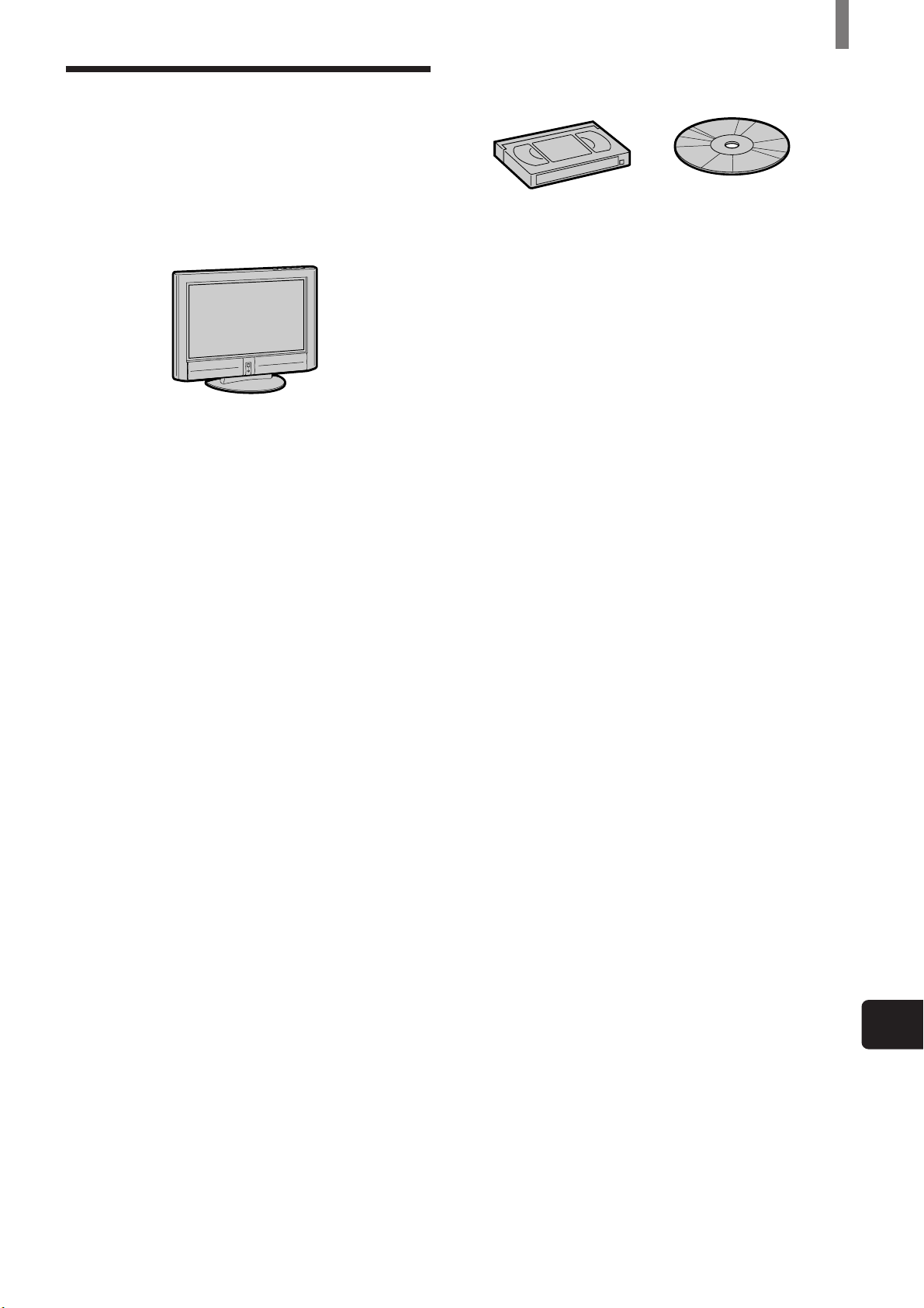
When watching movies on videotapes or
DVD
Set Picture Mode to “Movie” (page 26)
To adjust the picture quality
Select “Movie” and adjust the options, referring to the following
(See page 39).
• Set “Cine Motion” to “Auto” for smoothest presentation of
movies on screen (24 frame per second).
• If there is too much noise when watching a rental videotape,
increase “Noise Reduct.” (Noise Reduction). If the picture is
still noisy, decrease “Sharpness” to reduce noise.
• To enjoy high-level picture quality of DVD, increase
“Sharpness” to a degree where the picture appears clear, but
not overly sharp (See page 40).
Set Sound Mode to “Movie” (page 26)
To adjust the sound quality
Select “Movie” and adjust the options, referring to the following
(See page 27).
• For surround sound, set “Effect” to “TS” (TruSurround) (See
page 27).
Tip
Caption Vision is displayed if you activate the Closed Caption
feature (See page 24).
Notes on Image Retention
If the 1-5 images (below) are displayed for an extended
period of time, image retention (afterimage) in areas of the
screen may result due to the characteristics of the Plasma
Display Panel. It is possible to reduce image retention by
following steps A-C.
Situations which can result in burn-in and picture
retention
1 Black bars at the top and bottom that appear with wide video
source (Letter box picture)
2 Black bars to the left and right that appear with 4:3 video
source (conventional TV broadcast)
3 Video game sources
4 DVD on-screen menu displays
5 On-screen menus, channel numbers, etc., of connected
equipment such as DSS, Cable box, video decks, etc.
Precautions to avoid/reduce burn-in and picture
retention
A Use the automatic orbiting Screen Saver function.
B Avoid displaying channel numbers, on-screen menus etc. of
connected equipment such as DSS, Cable box, video decks,
etc. To erase channel numbers, on-screen menus, refer to the
user manual of connected equipment.
C Reduce brightness of the picture and/or display video source
in Wide Zoom or Full Mode.
US
(US) 25
Page 26
Watching the TV
Selecting the Picture
Press PICTURE MODE repeatedly until the desired
mode appears.
Mode
You can select one of the five different picture
modes that best suits the program you are watching.
You can also adjust the picture quality for the
Liv.Rm. (Living Room), Movie, and AV Pro modes
to suit your taste (See page 39).
When selecting Picture Mode, see “Enjoying Highquality Pictures and Sounds” on page 25.
You can set a different Picture Mode for each picture
signal format and store them in memory.
MUTING POWER
VCR/DVD
SAT/CABLE
SYSTEM
OFF
SLEEP
PICTURE
MODE
FUNCTION
VCR/DVD
SAT/CABLE
WIDE MODE DISPLAY
123
456
7809
JUMP
TV
TV
TV/VIDEO
PICTURE MODE
ENTER
If you press the button once, the current Picture
Mode appears. Each time you press the button, the
Picture Mode changes as follows.
PICTURE
MODE
,
Picture Mode : Vivid
Picture Mode :
Picture Mode : Liv.Rm.
Picture Mode : Movie
Picture Mode : AV Pro
Standard
Vivid
Select for enhanced picture contrast and sharpness.
Standard
Select to display a picture with contrast to suit your
room’s lighting conditions.
Liv.Rm. (Living Room)
Select to display a picture with moderate contrast,
which may better suit the living room’s lighting
conditions.
Adjust the options to your taste (See pages 39, 41).
Movie
Select to display a finely detailed picture. The sound
automatically changes to “TS” (TruSurround) (See
page 28).
Adjust the options to your taste (See pages 39, 41).
FAVORITES
TV/SAT
POWER
SAVING
VOL CH
CODE SET
MTS/SAP
GUIDE
MENU
AV Pro
Use this mode for your own custom settings (See
pages 39, 41).
26 (US)
Page 27
Watching the TV
Selecting the Effect
Mode
You can select one of the three different Effect
modes that best suits the program you are watching.
You can select the Effect mode, when watching the
picture of connected equipment as well.
TruSurround* produces a virtual surround effect, and
enables you to enjoy the sound effects of a movie
theater.
You can set a different Effect mode for each picture
signal format and store them in memory.
* TruSurround and the symbol are trademarks of SRS
Labs, Inc.
TruSurround technology is incorporated under license from
SRS Labs, Inc.
Tip
You can adjust other sound options. For details, see “Using the
Sound Control Option” on page 41.
1 Press PICTURE MODE repeatedly to select
“Liv.Rm.” (Living Room), “Movie,” or “AV
Pro.”
Note
Effect mode cannot be set for the “Vivid” and “Standard”
modes (See page 26).
PICTURE
MODE
,
Picture Mode : Liv.Rm.
Picture Mode : Movie
Picture Mode : AV Pro
2 Press MENU.
Picture/Sound Control
MENU
Picture Mode
Adjust Picture
Adjust
Sound
:
Liv.Rm.
,
select
ENTER
,,,to to
enter adj . menu
MUTING POWER
VCR/DVD
SYSTEM
OFF
SLEEP
PICTURE
MODE
FUNCTION
VCR/DVD
SAT/CABLE
SAT/CABLE
WIDE MODE DISPLAY
TV
TV
TV/VIDEO
123
456
7809
JUMP
FAVORITES
TV/SAT
POWER
SAVING
VOL CH
CODE SET
ENTER
MTS/SAP
GUIDE
MENU
1
3 - 6
2, 7
3 Press V/v to select (Picture/Sound Control),
then press
.
Picture/Sound Control
Picture Mode
Adjust Picture
Adjust
Sound
:
Liv.Rm.
,
,,,to to
set
4 Press V/v to select “Adjust Sound,” then press
.
Picture/Sound Control
Adjust
Sound
T reble
Bass
Bal ance
Effect Off
,
Reset
,,,to to
set
5 Press V/v to select “Effect,” then press .
Picture/Sound Control
Adjust ( )Liv Rm..
Sound
T reble
Bass
Bal ance
Effect Off
,
Reset
,,to
to return
ENTER
select
()
Liv.Rm.
:
ENTER
select
:
Hall
Simul.
TS
select
select press
ENTER
US
(Continued)
(US) 27
Page 28
Watching the TV
6 Press V/v to select “Hall,” “Simul.”
(Simulated), or “TS” (TruSurround), then press
.
Hall
Select for movies and music programs.
Simul. (Simulated)
Select for normal broadcast. It adds a surroundlike effect to mono programs.
TS (TruSurround)
Select for surround sound (for example, DVD
software). It produces a virtual surround effect.
Picture/Sound Control
Adjust
Sound
T reble
Bass
Bal ance
,
Effect
Reset
,,,to to
select
set
7 Press MENU to exit the menu screen.
()
Liv.Rm.
:
Hall
ENTER
Saving the Power Consumption
You can save the power consumption of the TV.
7809
JUMP
FAVORITES
TV/SAT
POWER
SAVING
VOL CH
CODE SET
ENTER
MTS/SAP
GUIDE
MENU
POWER SAVING
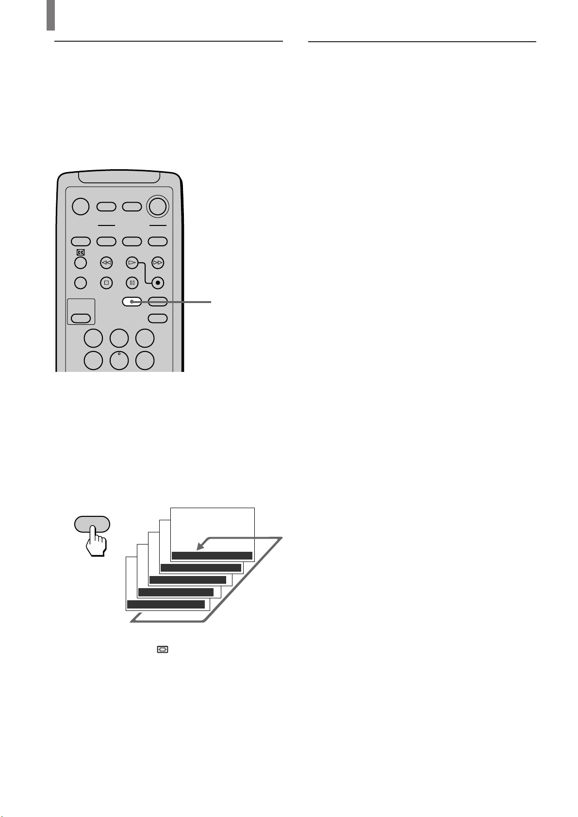
Press POWER SAVING.
POWER
SAVING
,
Power Saving : Reduce
To cancel the Power Saving mode
Press POWER SAVING again.
“Power Saving: Standard” appears.
Tips
• If you turn off the TV while the Power Saving mode is on, the
mode stays on next time you turn on the TV.
• You can set the Power Saving mode to on using the menu
screen. Select “Power Saving” in the
menu, then set it to “Standard” or “Reduce.”
• If you select “Liv.Rm.” (Living Room), “Movie” or “AV Pro”
using the PICTURE MODE button, you can adjust the picture
option even if the Power Saving mode is set to on (page 39).
Note that if you increase “Contrast” or “Brightness,” the
power consumption is not reduced.
(Custom Setup)
28 (US)
Page 29
Watching the TV
Using the Wide Screen Mode
Changing the Wide Screen Mode automatically
The Auto Wide Mode lets you watch 4:3 normal
broadcasts or other sizes of the picture such as
movies in several Wide Screen Modes (16:9 aspect
ratio). The following example shows the default
settings. (The “Auto Wide” screen mode is set to
“Mode2,” and “4:3 Default” is set to “Widezoom.”
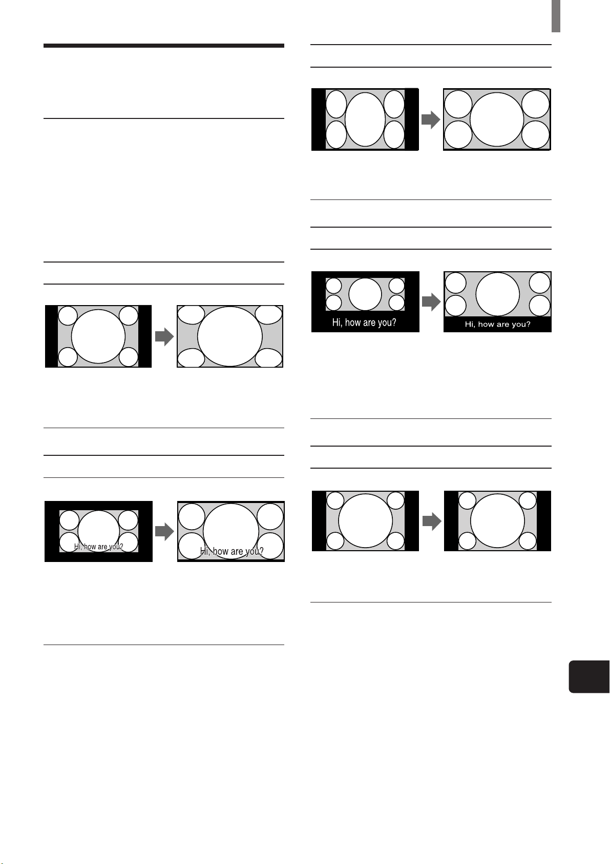
Widezoom
Original Picture
• Normal 4:3 aspect ratio
picture
• DTV 4:3 aspect ratio picture
Auto Wide
“Widezoom” enlarges the
4:3 picture to fill the 16:9
screen, keeping the
original image as much as
Full
Original Picture
• 4:3 squeezed video camera or
DVD picture
• DTV 16:9 aspect ratio picture
Subtitle
Original Picture
• Letter box movies with
subtitles outside the picture
(2.35:1 aspect ratio)
Auto Wide
“Full” stretches the 4:3
picture horizontally only,
to fill the 16:9 screen.
Auto Wide
“Subtitle” enlarges the
picture horizontally and
vertically to an equal
aspect ratio that fills the
screen, while the subtitle
area is compressed to fit
Zoom
Original Picture
• Letterbox movie of a video
tape or a DVD disc
Auto Wide
“Zoom” enlarges the 4:3
picture horizontally and
vertically to an equal
aspect ratio that fills the
16:9 screen. Useful for
watching Letterbox
Normal
Original Picture
• Normal 4:3 aspect ratio
picture
• DTV 4:3 aspect ratio picture
Auto Wide
“Normal” returns the 4:3
picture to its original size.
US
(Continued)
(US) 29
Page 30
Watching the TV
Changing the Wide Screen Mode manually
You can change the Wide Screen Mode manually
with the WIDE MODE button. When the antenna
reception is low, or the picture is too dark, the Auto
Wide function may not work properly. In this case,
set the Wide Screen Mode manually.
MUTING POWER
VCR/DVD
SYSTEM
OFF
SLEEP
PICTURE
MODE
FUNCTION
VCR/DVD
SAT/CABLE
SAT/CABLE
WIDE MODE DISPLAY
TV
TV
TV/VIDEO
WIDE MODE
123
456
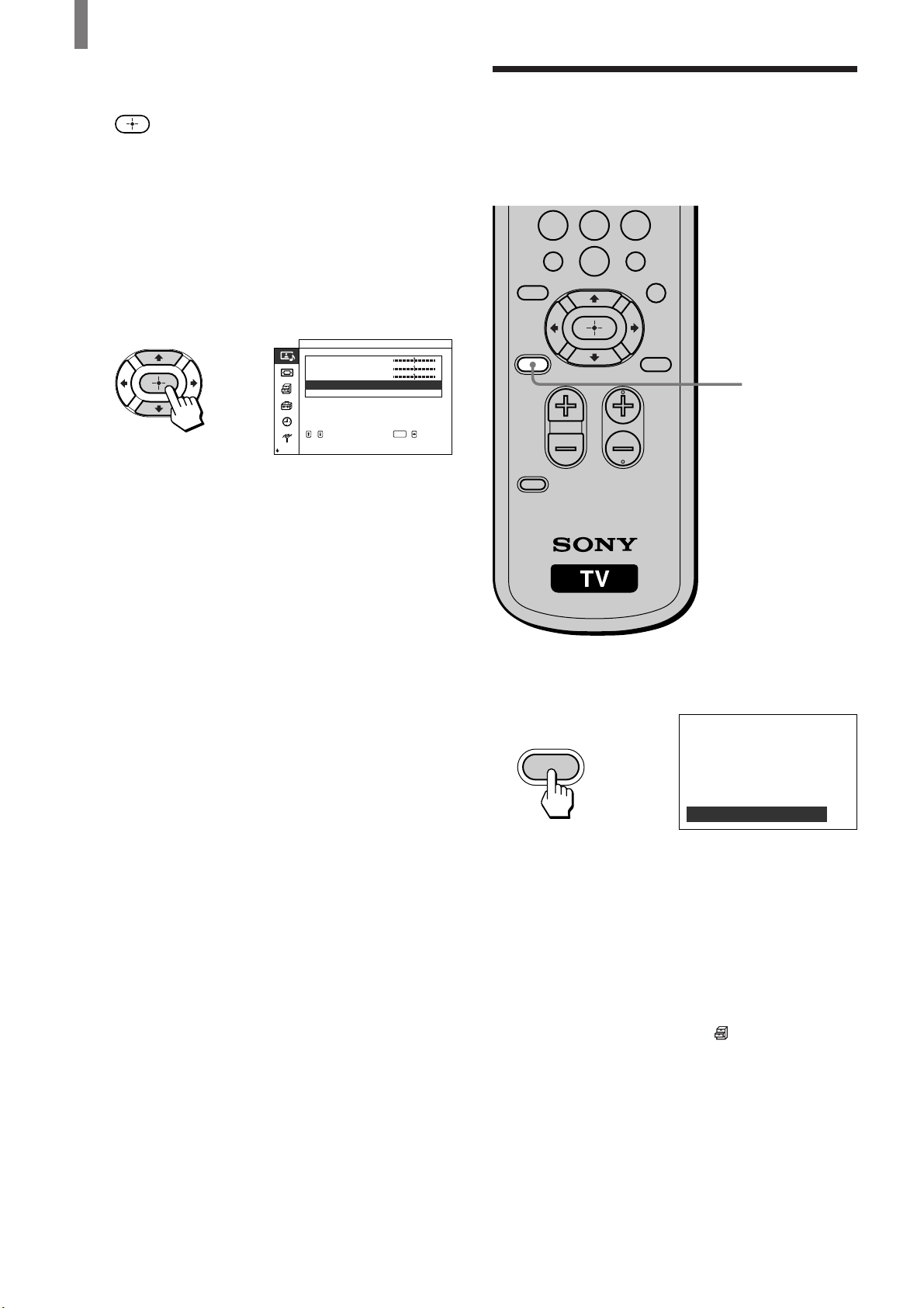
Press WIDE MODE repeatedly until the desired
Wide Screen Mode appears.
Changing the Wide Setup
Auto Wide setting has two options: “Mode1” and
“Mode2.”
Auto Wide: “Mode1”
Normal broadcast (4:3 aspect ratio) transmits the
control signal together with the picture signal. Some
video equipment, such as camcorders, transmit the
control signal*
the control signal and displays the picture with its
original aspect ratio. Note that black bands may
appear near the frame, or part of the picture may not
appear, if you select the Wide Screen Mode
manually while watching the picture without the
control signal.
Auto Wide: “Mode2”
In “Mode2,” the TV selects the best Wide Screen
Mode automatically to fit the wide screen, regardless
of the control signal.
The factory setting of this TV is:
“Auto Wide” is set to “Mode2,” and “4:3 Default” is set to
“Widezoom.”
1
Control signal which returns the picture to its original aspect
*
ratio. The following include the control signal.
– Pictures from camcorder with specified aspect ratio
– Broadcasts with the 4:3 aspect ratio signal
1
as well. In “Mode1,” the TV detects
Pressing the WIDE MODE button once lets the TV
select the best Wide Screen Mode, and the selected
Wide Screen Mode appears.* Each time you press
the button, Wide Screen Mode changes as follows.
For details on Wide Screen Mode, see page 29.
WIDE MODE
,
Wide Mode : Widezoom
Wide Mode : Zoom
Wide Mode : Full
Wide Mode : Subtitle
Wide Mode : Normal
* When “Auto Wide” in the (Screen Control) menu is set to
“Mode2,” and the “4:3 Default” is set to “Normal” (page 31),
the picture remains 4:3 aspect ratio (“Normal”).
Tip
Set “Auto Wide” to “Off” when changing the Wide Screen
Mode manually (See page 31).
30 (US)
Page 31

How Wide Screen Mode works in Auto Wide “Mode1” and “Mode2”
Wide Screen Mode
Original picture Auto Wide: “Mode1” Auto Wide: “Mode2”
Normal broadcasts
Broadcasts with the 4:3
aspect ratio signal*
Letterbox movies with subtitles
inside the picture
Letterbox movies with subtitles
outside the picture
Pictures from camcorder or DVD “Zoom” or “Full”
software with the 16:9 aspect ratio
3
signal*
Pictures from camcorder or DVD
software with the 4:3 aspect ratio
3
signal*
*2Set it on the menu screen (See below right). When purchasing, it is set to “Widezoom.”
3
Pictures with control signal (page 30).
*
3
Wide Screen Mode selected with the
WIDE MODE button
“Normal”
Wide Screen Mode selected with the
WIDE MODE button
Wide Screen Mode selected with the
WIDE MODE button
“Normal”
”Widezoom” or “Normal”*
”Widezoom” or “Normal”*
“Zoom”
“Subtitle”
“Widezoom” or “Normal”*
Watching the TV
2
2
2
Tips
• If you select the Wide Screen Mode manually (page 30), the
Wide Screen Mode may not change as noted above.
• If you press the WIDE MODE button (page 30) with Auto
Wide set to on, Auto Wide functions noted above. If you press
the WIDE MODE button repeatedly, Wide Screen Mode
changes as follows (according to the control signal).
– If the TV receives a picture with control signal, Wide
Screen Mode changes according to the control signal.
– If the TV receives a picture without control signal, Auto
Wide does not function even if “Auto Wide” is set to
“Mode2.” Note that it functions again when you select other
channels or inputs, or turn the TV off and on again.
• This TV features superior presentation of movie films by
identifying movie signals and processing them accordingly.
When Wide Screen Mode changes
automatically with Auto Wide set to on
• The TV receives the picture with a control signal
and selects the best Wide Screen Mode
automatically to fit the wide screen (See page 29).
• While “Auto Wide” is set to “Mode2,” the picture
size may change during commercial breaks. This is
because the TV selects the best Wide Screen Mode
automatically for each program (See page 29).
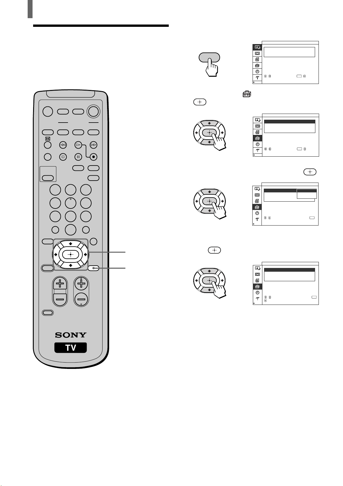
Changing the Auto Wide setting
For details on Auto Wide, see page 29.
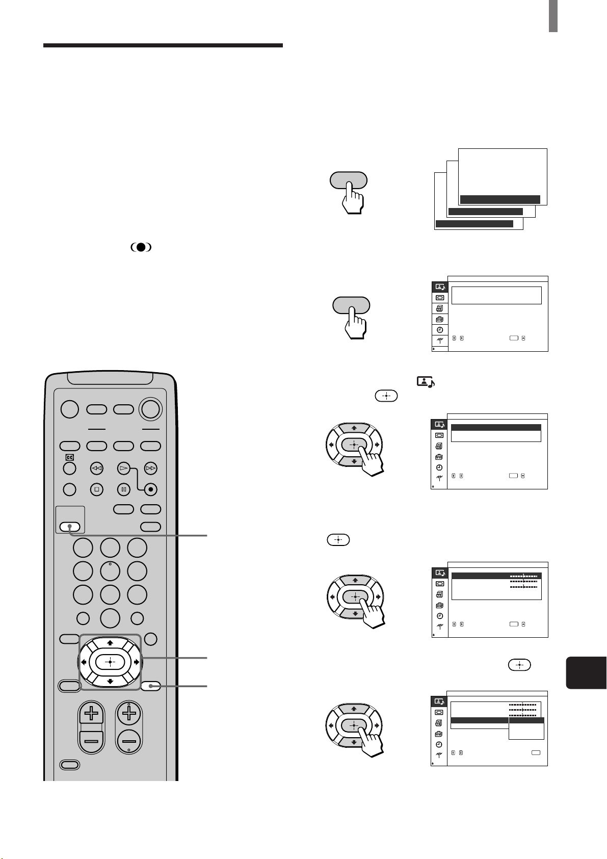
1 Press MENU.
2 Press V/v to select (Screen Control), then
press
.
3 Make sure that “Wide Setup” is selected, then
press
If not, press V/v to select “Wide Setup,” and
then press .
.
4 Press V/v to select “Auto Wide,” and then press
.
5 To set “Auto Wide” to “Off”:
Press V/v to select “Off,” then press
(Go to step 8.)
To set “Auto Wide” to “Mode1”:
Press V/v to select “Mode1,” then press
(Go to step 8.)
To set “Auto Wide” to “Mode2”:
Press V/v to select “Mode2,” then press
.
.
.
Notes on Wide Screen Mode
• The Wide Screen Mode function of this TV allows for various
display options: select the appropriate Wide Screen Mode for
the original aspect ratio of the picture you are watching.
• If you change the screen size using the WIDE MODE feature
with the TV installed in a public space for commercial use or
public purpose, it might be an infringement of copyright.
• If you select “Widezoom” when watching the picture with 4:3
aspect ratio, par of the picture is transformed. You can watch
the picture with its original aspect ratio in “Normal” mode.
• The upper and lower parts may not appear or subtitles may not
go in the screen according to the size of the original picture. In
this case, adjust the size or position (See page 38).
6 If you set “Auto Wide” to “Mode2,” press V/v
to select “4:3 Default,” then press
.
7 Press V/v to select “Normal” or “Widezoom,”
then press
.
8 Press MENU to exit the menu screen.
US
(US) 31
Page 32

Watching the TV
123
456
7809
ENTER
Setting the Video Inputs
You can enjoy images (and sound) from optional
video equipment connected to this unit by selecting
the appropriate input. For details on connection, see
pages 9 through 19.
MUTING POWER
VCR/DVD
SYSTEM
OFF
SLEEP
PICTURE
MODE
FUNCTION
VCR/DVD
123
456
7809
JUMP
FAVORITES
SAT/CABLE
SAT/CABLE
WIDE MODE DISPLAY
TV/VIDEO
ENTER
MTS/SAP
TV
TV
1
0-9 and ENTER
buttons
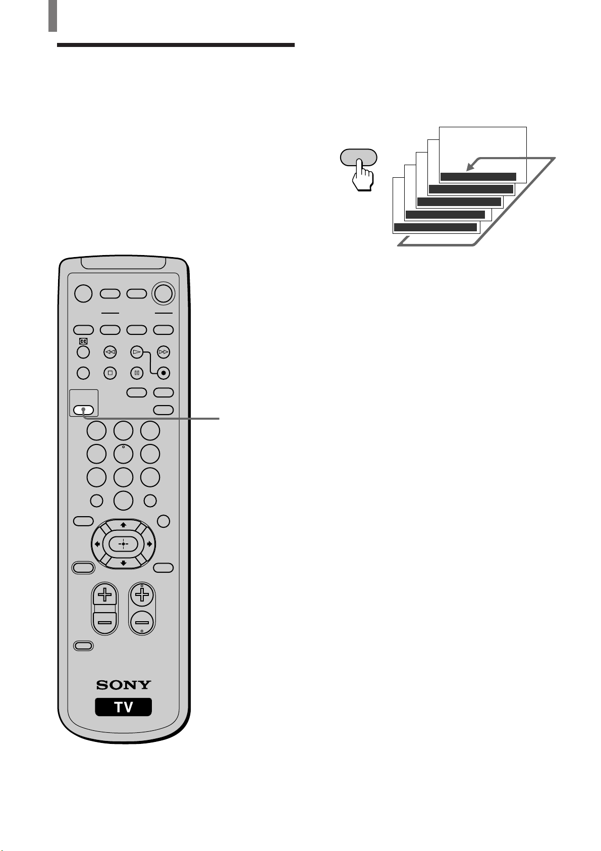
1 Press TV/VIDEO repeatedly until the desired
video input appears.
Each time you press TV/VIDEO, the input
changes as follows:
Select
• TV
• VIDEO IN 1
• VIDEO IN 2
• VIDEO IN 3
• VIDEO IN 4
* If a video equipment is connected to S VIDEO input and
“Auto YC” in the
(page 10), “S VIDEO1,” or “S VIDEO2” appears.
Display indication
TV T
r
VIDEO1*
r
VIDEO2*
r
VIDEO3
r
VIDEO4
(Custom Setup) menu is set to “On”
2 Operate the selected optional equipment.
For details, see “Operating Video Equipment
with your TV Remote Control” on page 33, or
refer to the instructions supplied with each
equipment.
When connecting optional video equipment
to VIDEO IN 4
TV/SAT
POWER
SAVING
VOL CH
CODE SET
GUIDE
MENU
CH +/–
Tip
You can select the inputs by using the INPUT button on the TV.
Each time you press the button, the input changes as follows:
TVtVIDEO1/S VIDEO1*tVIDEO2/S VIDEO2*
Rr
VIDEO 4 T VIDEO 3
1 Press MENU.
2 Press V/v to select (Initial Setup), then press
.
3 Press V/v to select “Video 4 Mode,” then press
.
4 Press V/v to select “Y/PB/PR” or “RGB,” then
press
.
5 Press MENU to exit the menu screen.
To watch the TV
Press the 0-9 and ENTER buttons or CH +/–.
CH
or
32 (US)
Page 33

Operating Video
Watching the TV
The remote control is preset to operate Sony brand
video equipment.
Equipment with Your TV
Remote Control
Programming the remote control
5
MUTING POWER
VCR/DVD
SYSTEM
OFF
FUNCTION
VCR/DVD
SAT/CABLE
SAT/CABLE
TV
TV
2
SLEEP
WIDE MODE DISPLAY
PICTURE
MODE
123
TV/VIDEO
Sony equipment
Beta, ED Beta VCRs
8mm VCR
VHS VCR
DV VCR
DVD player
Programmable code number
303
302
301
348
751
If you have video equipment other than Sony brand
that you want to control with the TV’s remote
control, use the following procedures to program the
remote control.
Note
The equipment must have infrared (IR) remote capability in
order to be used with this remote control.
From the “Manufacturer’s codes” listed on page 34,
select the three-digit code number for the
manufacturer’s code of your equipment. If more than
one code number is listed, start with the number
listed first. Use the code number to complete the
following procedure.
456
7809
JUMP
FAVORITES
TV/SAT
POWER
SAVING
VOL CH
CODE SET
ENTER
MTS/SAP
GUIDE
MENU
3
4
1
1 Press CODE SET.
2 Press the function button you want to program.
To program a cable box or a satellite receiver
Press SAT/CABLE (FUNCTION).
To program video equipment
Press VCR/DVD (FUNCTION).
3 Enter the three-digit manufacturer’s code number
using the 0-9 buttons.
4 Press ENTER.
5 To check if the code number works, aim the
TV’s remote control at the equipment and press
the VCR/DVD and/or SAT/CABLE (POWER)
button that corresponds with that equipment. If it
responds, the programming is completed. If not,
try using the other codes listed for that
manufacturer.
Tips
• If more than one number is listed, try entering them one by
one until you come to the correct code for your equipment.
• If you enter a new code number, the code number you
previously entered at that setting is erased.
• In some rare cases, you may not be able to operate your
equipment with the Sony remote control. In this case, use the
equipment’s own remote control unit.
US
(Continued)
(US) 33
Page 34

Watching the TV
Manufacturer’s codes
VCRs
Manufacturer Code
Sony 301
Admiral (M. Ward) 327
Aiwa 338, 344
Audio Dynamic 314, 337
Broksonic 319, 317
Canon 309, 308
Citizen 332
Craig 302, 332
Criterion 315
Curtis Mathes 304, 338, 309
Daewoo 341, 312, 309
DBX 314, 336, 337
Dimensia 304
Emerson 319, 320, 316,
317, 318, 341
Fisher 330, 335
Funai 338
General Electric 329, 304, 309
Go Video 322, 339, 340
Goldstar 332
Hitachi 306, 304, 305,
338
Instant Replay 309, 308
JC Penney 309, 305, 304,
330, 314, 336,
337
JVC 314, 336, 337,
345, 346, 347
Kenwood 314, 336, 332,
337
LXI (Sears) 332, 305, 330,
335, 338
LG 332
Magnavox 308, 309, 310
Marantz 314, 336, 337
Marta 332
Memorex 309, 335
Minolta 305, 304
Mitsubishi/MGA 323, 324, 325,
326
Multitech 325, 338, 321
NEC 314, 336, 337
Olympic 309, 308
Optimus 327
Panasonic 308, 309, 306,
307
Manufacturer Code
Pentax 305, 304
Philco 308, 309
Philips 308, 309, 310
Pioneer 308
Quasar 308, 309, 306
RCA/PROSCAN 304, 305, 308,
309, 311, 312,
313, 310, 329
Realistic 309, 330, 328,
335, 324, 338
Sansui 314
Samsung 322, 313, 321
Sanyo 330, 335
Scott 312, 313, 321,
335, 323, 324,
325, 326
Sharp 327, 328
Shintom 315
Signature 2000 338, 327
(M. Ward)
SV2000 338
Sylvania 308, 309, 338,
310
Symphonic 338
Tashiro 332
Tatung 314, 336, 337
Teac 314, 336, 338,
337
Technics 309, 308
Toshiba 312, 311
Wards 327, 328, 335,
331, 332
Yamaha 314, 330, 336,
337
Zenith 331
DVD Players
Manufacturer Code
Sony 751
Panasonic 753
Pioneer 752
RCA 755
Toshiba 754
Cable Boxes
Manufacturer Code
Sony 230
Hamlin/Regal 222, 223,
224, 225, 226
Jerrold/G. I. 201, 202, 203,
204, 205, 206,
207, 208, 218
Oak 227, 228, 229
Panasonic 219, 220, 221
Pioneer 214, 215
Scientific Atlanta 209, 210, 211
Tocom 216, 217
Zenith 212, 213
Satellite Receivers
Manufacturer Code
Sony 801
General Electric 802
Hitachi 805
Hughes 804
Panasonic 803
RCA/PROSCAN 802, 808
Toshiba 806, 807
34 (US)
Page 35

Watching the TV
Operating optional equipment
POWER buttons
(VCR/DVD, SAT/
MUTING POWER
VCR/DVD
SYSTEM
OFF
SLEEP
PICTURE
MODE
FUNCTION
VCR/DVD
SAT/CABLE
SAT/CABLE
WIDE MODE DISPLAY
TV
TV
TV/VIDEO
123
CABLE)
FUNCTION
buttons (VCR/
DVD, SAT/
CABLE)
VCR/DVD
operating buttons
DISPLAY
0-9 buttons
456
7809
JUMP
FAVORITES
TV/SAT
POWER
SAVING
VOL CH
ENTER
MTS/SAP
GUIDE
MENU
ENTER
JUMP
GUIDE
V, v, B, b,
MENU
Operating a DVD player
To
Turn on/off
Control a DVD player
Play
Stop
Pause
Step through different
tracks of an audio disc
Step through different
chapters of a video disc
Select tracks directly
Display the menu (Setup)
Operate the DVD menu
Press
VCR/DVD (POWER)
VCR/DVD (FUNCTION)
H
s
S (press again to resume normal
playback)
J to step forward or j to step
backward
CH + to step forward or CH – to
step backward
0-9 buttons
MENU
V, v, B, b,
Operating a cable box
To
Turn on/off
Select cable box
Select a channel
Change channels
Go to previous channel
Press
SAT/CABLE (POWER)
SAT/CABLE (FUNCTION)
0-9 buttons, ENTER
CH +/–
JUMP
CODE SET
Operating a VCR
To
Turn on/off
Control a VCR
Change channels
Record
Play
Stop
Fast forward
Rewind the tape
Pause
Search the picture
forward or backward
CH +/–
Press
VCR/DVD (POWER)
VCR/DVD (FUNCTION)
CH +/–
H and z simultaneously
H
s
J
j
S (press again to resume normal
playback)
J or j during playback
(release to resume normal playback)
Operating a satellite receiver
To
Turn on/off
Select satellite receiver
Select a channel
Change channels
Go to previous channel
Display channel number
Display DBS guide
Display DBS menu
Move highlight (cursor)
Select item
Press
SAT/CABLE (POWER)
SAT/CABLE (FUNCTION)
0-9 buttons, ENTER
CH +/–
JUMP
DISPLAY
GUIDE
MENU
V, v, B, b,
US
(US) 35
Page 36

Watching the TV
Using Favorite Channels
You can select programs from a list of favorite
channels that you preset.
Setting your favorite channels
MUTING POWER
VCR/DVD
SYSTEM
OFF
SLEEP
PICTURE
MODE
FUNCTION
VCR/DVD
123
456
7809
JUMP
FAVORITES
SAT/CABLE
SAT/CABLE
WIDE MODE DISPLAY
TV
TV
TV/VIDEO
ENTER
MTS/SAP
2 Press V/v to select (TV Setup), then press
.
TV Set up
Fav or i t e Channel
,
Auto Program
Channe l Sk i p Add/
Cable
Channel F i x
,,,to to
enter set menu
select
::
:
ENTER
3 Press V/v to select “Favorite Channel,” then
press
.
,
TV Set up
Fav or i t e Channel
Fav or ite No. 1 1CH
,,,to to
set
select
:
:
22
:
33
:
44
:
55
:
66
:
77
:
88
ENTER
4 Press V/v to select the position you want to
change, then press
,
.
TV Set up
Fav or i t e Channel
Fav or ite No.
,,to
to return
:
11CH
:
22
:
33
:
44
:
CH
55
:
66
:
77
:
88
select press
off
off
ENTER
TV/SAT
POWER
SAVING
VOL CH
CODE SET
1 Press MENU.
MENU
GUIDE
MENU
,
2 - 6
1, 7
Picture/Sound Control
Picture Mode Standard
Adjust Picture
Adjust
,,,to to
enter adj . menu
Sound
select
:
ENTER
5 Press V/v to select the desired channel, then
press
You have now selected a favorite channel for the
position selected in step 4.
.
,
TV Set up
Fav or i t e Channel
Fav or ite No.
,,,to to
set
select
:
11CH
:
22
:
33
:
44
:
524
:
66
:
77
:
88
ENTER
6 Repeat steps 4 and 5 to program other favorite
channels.
7 Press MENU to exit the menu screen.
36 (US)
Page 37

Watching Favorite Channel
MUTING POWER
VCR/DVD
SAT/CABLE
TV
Watching the TV
SYSTEM
OFF
SLEEP
PICTURE
MODE
FUNCTION
VCR/DVD
123
456
7809
JUMP
FAVORITES
TV/SAT
POWER
SAVING
VOL CH
SAT/CABLE
WIDE MODE DISPLAY
TV
TV/VIDEO
ENTER
MTS/SAP
GUIDE
MENU
1
2
1 Press FAVORITES.
The Favorite Channel options appear.
FAVORITES
,
TV/SAT
Favo ri tes
1
2
3
4
42
6
7
8
2 Press V/v to select the desired channel, then
press
The selected channel will be displayed.
.
,
42
US
(US) 37
Page 38

Adjusting Your Setup
Wide Setu p
:
:
,,,to to
set
select
ENTER
Screen Control
Normal
Wide Mode
ScreenHZoom
Pixel
VSize
Size
HShift
Sh ift
V
Adjust
Adjusting Your
Setup
Adjusting the Picture Size/Position
You can adjust the size and position of the picture for
each Wide Screen Mode (page 29) in the following
cases:
• To move the position of the picture in
“Widezoom” and “Zoom” modes
• When subtitles may not go in the screen in
“Subtitle” mode
”H Size” (Horizontal Size) and “H Shift” (Horizontal
Shift) cannot be adjusted in “Widezoom.”
MUTING POWER
VCR/DVD
SAT/CABLE
TV
1 Receive the picture you want to adjust, then
press MENU.
Picture/Sound Control
MENU
,
Picture Mode Standard
Adjust Picture
Adjust
,,,to to
enter adj . menu
Sound
select
:
ENTER
2 Press V/v to select the (Screen Control), then
press
.
,
Screen
Control
Wide Se tup
Wide
Mode
Screen Zoom::
Screen Siz e
Screen
Adjust
Reset
,,,to to
enter set menu
Sh ift
Pixel
select
Normal
ENTER
3 Press V/v to select the option you want to
adjust.
To adjust screen size
Press V/v to select “Screen Size,” then press
.
SYSTEM
VCR/DVD
OFF
SLEEP
PICTURE
MODE
123
456
7809
JUMP
FAVORITES
TV/SAT
POWER
SAVING
VOL CH
FUNCTION
SAT/CABLE
WIDE MODE DISPLAY
TV
TV/VIDEO
ENTER
MTS/SAP
GUIDE
MENU
2 - 4
1, 5
,
H Size 00
V Size 00
To adjust screen position
Press V/v to select “Screen Shift,” then press
.
,
H Shift 00
V Shift 00
Note
The menu screen changes as follows when “Menu
Function” is set to “Return” in the (Initial Setup) menu.
38 (US)
Page 39

Adjusting Your Setup
4 Press V/v/B/b to adjust each option, then press
.
To adjust the “Screen Size”
Enlarges
vertically
Shrinks
horizontally
Enlarges
horizontally
Shrinks
vertically
To adjust the “Screen Shift”
Moves up Moves to
Moves to
the left
the right
Moves
down
5 Press MENU to exit the menu screen.
Using the Picture Control Mode Option
You can precisely set the picture quality with
“Liv.Rm.” (Living Room), “Movie,” or “AV Pro”
(selected with the PICTURE MODE button).
You can set a different picture control option for
each picture signal format and store them in
memory.
MUTING POWER
VCR/DVD
SYSTEM
OFF
SLEEP
PICTURE
MODE
FUNCTION
VCR/DVD
SAT/CABLE
SAT/CABLE
WIDE MODE DISPLAY
TV
TV
TV/VIDEO
123
456
7809
JUMP
FAVORITES
TV/SAT
POWER
SAVING
VOL CH
CODE SET
1
ENTER
MTS/SAP
GUIDE
3 - 7
MENU
2, 8
(Continued)
(US) 39
US
Page 40

Adjusting Your Setup
1 Press PICTURE MODE repeatedly until
“Liv.Rm.” (Living Room), “Movie,” or “AV
Pro” appears.
Note
The picture control option cannot be adjusted in “Vivid” or
“Standard” modes (See page 26).
PICTURE
MODE
,
Picture Mode : Liv.Rm.
Picture Mode : Movie
Picture Mode : AV Pro
2 Press MENU.
Picture/Sound Control
MENU
Picture Mode
Adjust Picture
Adjust
Sound
:
Liv.Rm.
,
,,,to to
select
enter adj . menu
3 Press V/v to select (Picture/Sound Control),
then press
.
Picture/Sound Control
Picture Mode
Adjust Picture
Sound
Adjust
ENTER
:
Liv.Rm.
,
,,,to to
select
set
ENTER
5 Press V/v to select the option you want to
adjust, then press
.
,
Contrast 204
6 Press V/v/B/b to make the desired adjustment,
then press
Adjustable options
Option
Contrast
Brightness
Color
Hue
Sharpness
.
,
Press v/B
To reduce picture
contrast
To darken the
picture
To decrease color
intensity
To decrease the
green tones
To soften the
picture
Picture/Sound Cont r o l
PictureAdjust
Contr ast
Brightness
Color
Hue
Sharpness
Noise Reduct.
Cine Motion
Dynamic
,,,to to
set
()
:
:
Pictur
:
select
Liv.Rm.
ENTER
Press V/b
To enhance picture
contrast
To brighten the
picture
To increase color
intensity
To increase the
green tones
To sharpen the
picture
Low
Of f
On
4 Press V/v to select “Adjust Picture,” then press
.
,
Picture/Sound Control
PictureAdjust
Con trast
Brightness
Color
Hue
Shar pness
Noise Reduct.
Cine Motion
Dynamic
,,,to to
set
Pictur
select
()
Liv.Rm.
Low
:
Of f
:
On
:
ENTER
Tip
Option adjustments are indicated by a numerical value.
40 (US)
Page 41

If you press and hold v, the following options
appear.
Adjusting Your Setup
Using the Sound Control
Picture/Sound Control
Adjust
Sharpness
Noise Reduct.
C ine Motion
Dynamic
Color Temp.
Color Correct.
Gamma C orrect.
Reset
,,,to to
set
Adjustable options
Option
Noise
Reduct.
(Noise
Reduction)
Cine Motion
Dynamic
Picture
Color
Temp.
(Color
Temperature)
Color
Correct.
(Color
Correction)
Gamma
Correct.
(Gamma
Correction)
Description
Select to reduce the noise
level of equipment
connected to the VHF/
UHF, VIDEO IN* jacks.
It is most effective on the
signal from the VHF/
UHF jack.
Obtains a smooth picture
movement that
approaches the original
film-like quality when
reproducing movies or
other video sources on 24
frame per second films.
Select to enhance the
picture contrast.
Select to give bright
colors a red tint (Setting
variable from “Cool” to
“Warm”).
Select to emphasize reds
and blues.
Select to adjust the
balance between bright
and dark areas of the
picture.
Picture
Picture
select
()
Liv.Rm.
Low
:
Of f
:
On
:
:
Cool
On
:
Mid
:
ENTER
Setting
Off/Low/
Mid (Middle)/
High
Auto/Off
On/Off
Cool/Neutral/
Warm/
USER1**/
USER2**/
USER3**
On/Off
High/
Mid (Middle)/
Low
Option
You can precisely adjust the sound settings for
“Liv.Rm.” (Living Room), “Movie,” or “AV Pro”
(selected with the PICTURE MODE button).
You can set a different sound control option for each
picture signal format and store them in memory.
For details on Effect mode, see page 27.
MUTING POWER
VCR/DVD
SYSTEM
VCR/DVD
OFF
SLEEP
PICTURE
MODE
123
456
7809
JUMP
FAVORITES
TV/SAT
POWER
SAVING
VOL CH
SAT/CABLE
FUNCTION
SAT/CABLE
WIDE MODE DISPLAY
TV
TV
TV/VIDEO
1
ENTER
MTS/SAP
GUIDE
3 - 7
MENU
2, 8
* You cannot adjust “Noise Reduct.” (Noise Reduction) for
an equipment connected only to the RGB (Y/G, P
R) input.
**For details on these settings, see page 51.
7 Repeat steps 5 and 6 to adjust other options.
8 Press MENU to exit the menu screen.
To reset to the factory settings
Select “Reset” in step 5, then press
.
B/B, PR/
CODE SET
US
(Continued)
(US) 41
Page 42

Adjusting Your Setup
1 Press PICTURE MODE repeatedly until
“Liv.Rm.” (Living Room), “Movie,” or “AV
Pro” appears.
Note
The sound control option cannot be adjusted in “Vivid” or
“Standard” modes (page 26).
PICTURE
MODE
,
Picture Mode : Liv.Rm.
Picture Mode : Movie
Picture Mode : AV Pro
2 Press MENU.
MENU
Picture/Sound Control
Picture Mode
Adjust Picture
Sound
Adjust
,
,,,to to
select
enter adj . menu
:
Liv.Rm.
ENTER
6 Press V/v/B/b to make the desired adjustment,
then press
Option
Treble
Bass
Balance
Effect
Tip
Option adjustments are indicated by a numerical value.
.
Press v/B
To decrease higherpitched sounds.
To decrease lowerpitched sounds.
To emphasize the
left speaker.
See page 27.
Press V/b
To increase higherpitched sounds.
To increase lowerpitched sounds.
To emphasize the
right speaker.
7 Repeat steps 5 and 6 to adjust other options.
8 Press MENU to exit the menu screen.
3 Press V/v to select (Picture/Sound Control),
then press
.
Picture/Sound Control
Picture Mode
Adjust Picture
Adjust
Sound
:
Liv.Rm.
,
,,,to to
select
set
4 Press V/v to select “Adjust Sound,” then press
.
Picture/Sound Control
Adjust
Sound
T reble
Bass
Bal ance
Effect Off
,
Reset
,,,to to
select
set
5 Press V/v to select the option you want to
adjust, then press
.
ENTER
()
Liv.Rm.
:
ENTER
To reset to the factory settings
Select “Reset” in step 5, then press
.
42 (US)
,
Treble +20
Page 43

Adjusting Your Setup
Selecting Stereo or Bilingual Programs
You can enjoy stereo, bilingual and mono programs.
7809
JUMP
FAVORITES
TV/SAT
POWER
SAVING
VOL CH
CODE SET
ENTER
MTS/SAP
MTS/SAP
GUIDE
MENU
Using the Parental Control Feature
The TV programs and movies shown on TV are
given a rating signal based on the following rating
systems.
In U.S.A.: U.S. Television Parental Guidelines to
rate television programs (U.S. TV ratings), and
Motion Picture Association of America (MPAA)
Guidelines to rate movies including those shown on
TV (movie ratings).
In Canada: Canadian English Language ratings to
rate television programs in English, and Canadian
French Language ratings to rate those in French.
To block programs you feel are unsuitable for your
children, you need to set the TV for the desired
rating systems. Sony’s predetermined ratings are also
available. See page 48 for a description of the
ratings.
Press MTS/SAP repeatedly until the desired sound
indication appears.
Each time you press the button, the sound indication
changes as follows:
MTS/SAP
,
GUIDE
Sound indication
Stereo
Auto-SAP
Mono
Description
Select for stereo reception when
viewing a program broadcast in stereo.
Select to automatically switch the TV
to second audio programs when a signal
is received. (If no SAP signal is
present, the TV remains in Stereo
mode.)
Select for mono reception. (Use to
reduce noise during weak stereo
broadcasts.)
MTS : Stereo
MTS : Auto
MTS : Mono
SAP-
The TV’s Parental Control feature functions by
receiving the rating signal from your local
broadcasting station or cable service provider.
US
(Continued)
(US) 43
Page 44

Adjusting Your Setup
123
456
7809
123
456
7809
Activating the Parental Control feature
MUTING POWER
VCR/DVD
SYSTEM
OFF
SLEEP
PICTURE
MODE
FUNCTION
VCR/DVD
SAT/CABLE
SAT/CABLE
WIDE MODE DISPLAY
TV
TV
TV/VIDEO
123
456
4 - 5
7809
JUMP
FAVORITES
ENTER
MTS/SAP
3 Make sure that “Parental Control” is selected,
then press
.
Custom Set up
Pa rental Control
Enter Passwo r d
– –––
,
4 Enter a four digit password using the 0-9 buttons.
The factory preset password is “0000.”
Custom Set up
Pa rental Control
Con f i rm Pas sword
,
Note
Do not enter “4357” corresponding to “HELP” on a phone
number pad (See page 45).
– –––
TV/SAT
POWER
SAVING
VOL CH
GUIDE
MENU
2 - 3,
6 - 9
1, 10
1 Press MENU.
Picture/Sound Control
MENU
Picture Mode Standard
Adjust Picture
Adjust
:
Sound
,
select
ENTER
:
Standard
:
Stereo
:
:
:
:
ENTER
,,,to to
enter adj . menu
2 Press V/v to select (Custom Setup), then
press
.
,
Custom Set up
Pa rental Control
Powe r Saving
MTS
Speaker
Caption Vision
Display
Screen
Saver
YC
Auto
,,,to to
select
enter set menu
On
Of f
On
5 Confirm your password by entering it again.
Your password is stored and the Parent menu
options appear.
Custom Set up
Pa rental Control
Lock
Coun t r y
,
Change Passwo rd
,,,to to
set
Tips
• You need to enter the password here for any feature
access into the Parental Control menu. If you lose your
password, see “Tip” on page 45.
• If you want to change the password, see page 45.
select
:
:
ENTER
U.S A.
Of
6 Press V/v to select “Country,” then press .
Custom Set up
Pa rental Control
Lock
Coun t r y
Change Passwo rd
:
:
:
U.S A.
Canada
Off
,
select,,to
select press
to return
ENTER
f
44 (US)
Page 45

7 Press V/v to select your country (U.S.A. or
Canada), then press
.
Custom Set up
Pa rental Control
Lock
Coun t r y
Change Passwo rd
:
:
Canada
,
,,,to to
set
8 Press V/v to select “Lock,” then press .
Custom Set up
Pa rental Control
Lock
Coun t r y
Change Passwo r d
,
to return
ENTER
select
:
Off
:
Ch i l d
Youth
Y.
Adult
Custom
select,,to
select press
Off
ENTER
Adjusting Your Setup
To deactivate the Parental Control feature
Set “Lock” to “Off” in the Parental Control menu.
To change the password
1 Select “Parental Control” from the (Custom
Setup) menu (See page 44).
2 Enter your four digit password using the 0-9
buttons.
The “Parental Control” menu appears.
3 Press V/v to select “Change Password,” then
press
.
4 Enter a new four digit password using 0-9
buttons.
5 Enter the password set in step 4 again to confirm,
then press
.
6 Press MENU to exit the menu screen.
9 Press V/v to select a desired rating , then press
.
If you select “Child,” “Youth,” or “Y.Adult”
(Young Adult), the Parental Control is activated
automatically.
Custom Set up
Pa rental Control
Lock
Coun t r y
Change Passwo rd
:
:
Ch i l d
Canada
,
,,,to to
select
set
If you want to select the ratings from “Custom,”
see “Selecting a Custom Rating” on page 46.
10
Press MENU to exit the menu screen.
Viewing blocked programs
You can view a blocked programs by entering the
password.
ENTER
Tip
If you have forgotten your password, enter the master password
“4357” (corresponding to “HELP” on a phone number pad) in
step 2. You can then store a new password.
Notes
• If you entered “4357” as your password the first time, you
cannot store a new password (See step 4 of “Activating the
Parental Control feature” on page 44).
• When you select a Parental Control program and the s
indicator is displayed on the screen, you cannot view that
program even if you enter “4357.” (See “Viewing blocked
programs” on the left.)
1 Press ENTER to display the “Password” screen.
2 Enter your password using the 0-9 buttons.
The Parental Control feature will be canceled
(“Lock” set to “Off”) until you turn the TV off.
US
(US) 45
Page 46

Adjusting Your Setup
Selecting a Custom Rating
If you want to select the ratings to be blocked from
Custom once you have activated the Parental Control
feature (page 44), follow the procedure below.
For a detailed description of each rating, see “What
the Ratings Mean” on page 48.
MUTING POWER
VCR/DVD
SYSTEM
OFF
SLEEP
PICTURE
MODE
FUNCTION
VCR/DVD
SAT/CABLE
SAT/CABLE
WIDE MODE DISPLAY
TV
TV
TV/VIDEO
123
3 Make sure that “Movie Rating” is selected, then
press
.
,
Custom Set up
Pa rental Control
Custom
Movie Rati ng
–:
G
–:
PG
–:
PG13
–:
R
–:
NC17
–:
X
4 Press V/v to select the rating to be blocked, then
press
The s indication automatically appears beside
the selected rating and all “higher” ratings,
indicating that the programs that match the
ratings will be blocked.
.
,
Custom Set up
Pa rental Control
Custom
Movie Rati ng
–:
G
:
PG
:
PG13
:
R
:
NC17
:
X
456
7809
JUMP
FAVORITES
TV/SAT
POWER
SAVING
VOL CH
ENTER
MTS/SAP
GUIDE
MENU
2 - 9
10
1 Perform the steps 1 to 8 in “Activating the
Parental Control feature” on page 44 to display
the Parental Lock options.
2 Press V/v to select “Custom,” then press .
In U.S.A.
Custom Set up
Pa rental Control
Custom
Mo vie Rat i ng
TV
Ra ting
Un r a ted Al low
:
,
5 Press B to return to the “Custom” menu.
Custom Set up
Pa rental Control
Custom
Mo vie Rat i ng
TV
Ra ting
Un r a ted Al low
,
,,,to to
select
set
6 To select a TV rating in U.S.A.:
Press V/v to select “TV Rating,” then press
.
Custom Set up
Pa rental Control
Custom
TV Ra ting
– –:
TV Y
–––:
TV Y7
––:
,
TV G
––
TV PGFVD
–:
–
TV 14
–:
–
TV MA
set
–:
L–S–V
D–L–S–V
L–S–V
select
:
ENTER
,,,, to to
–
–
–
ENTER
46 (US)
,,,to to
select
set
In Canada
Custom Set up
Pa rental Control
Custom
Eng lish
F rench
U.S.A .
set
Ra ting
Ra ting
Ra ting
,,,to to
select
To select a rating in Canada, go to step 6.
ENTER
ENTER
Page 47

Adjusting Your Setup
To select a TV ratings in Canada:
Press V/v to select “English Rating,” “French
Rating,” or “U.S.A. Rating,” then press
English Rating
Custom Set up
Pa rental Control
Custom
Eng lishRating
–:
C
–:
+
C8
–:
,
G
–:
PG
–:
+
14
–:
+
18
French Rating
Custom Set up
Pa rental Control
Custom
F rench
Rating
G
+
8ans
+
13ans
+
16ans
+
18ans
U.S.A. Rating
Custom Set up
Pa rental Control
Custom
U.S.A . Ra ting
– –:
TV Y
–––:
TV Y7
––:
TV G
––
TV PGFVD
–:
–
TV 14
–:
–
TV MA
set
–:
–:
–:
–:
–:
–:
L–S–V
D–L–S–V
L–S–V
select
.
–
–
–
ENTER
,,,, to to
7 Press V/v to select the TV rating to be blocked,
then press
.
8 Press B/b to select the extender to be viewed,
then press
“–” appears beside the selected extender,
indicating that the programs that match the
extender can be viewed.
If you re-press
the programs that match the extender will be
blocked again.
.
Custom Set up
Pa rental Control
Custom
TV Ra ting
––:
TV Y
–––:
TV Y7
––:
,
TV G
–––:
TV PGFVD
–:
TV 14
–:
TV MA
to
set
, s is displayed to show that
–
S–V
L
–
DL SV
LSV
,,,, to
select
–
ENTER
9 Repeat step 8 for other extenders.
All programs that match the ratings you select
and higher, except for the extenders that were
canceled, will be blocked.
10
Press MENU to exit the menu screen.
To block TV programs and/or movies for
which a rating is not given (NR and N/A)
For a description of the NR and N/A ratings, see
page 48.
The s indication automatically appears beside
the selected rating and all “higher” ratings,
indicating that the programs that match the
ratings will be blocked.
Example: TV rating in U.S.A.
Custom Set up
Pa rental Control
Custom
TV Ra ting
––:
TV Y
–––:
TV Y7
––:
,
TV G
–––:
TV PGFVD
–:
TV 14
–:
TV MA
set
L–S–V
DL SV
LSV
,,,, to to
select
–
ENTER
Some U.S.TV ratings have additional content
ratings called “extenders.” The extenders are
defined as follows: D (sexually suggestive
Dialog), FV (Fantasy Violence), L (coarse
Language), S (Sexual situations) and V
(Violence). By setting the extenders, you can
define additional viewing limits. For more details
of extenders, see page 49.
All of the extenders included in the selected
ratings will be blocked. If you wish to allow any
of them to be viewed, go to step 8.
1 Perform steps 1-2 of “Selecting a Custom
Rating” on page 46.
2 Press V/v to select “Unrated,” then press .
3 Press V/v to select “Block,” then press .
4 Press MENU to exit the menu screen.
US
(US) 47
Page 48

Adjusting Your Setup
What the Ratings Mean
Ratings in the U.S.A.
Sony’s predetermined ratings
These are original ratings that Sony has
predetermined according to the viewer’s age. Each
rating allows for viewing of certain programs, as
follows. (See the next column for a description of
TV and movie ratings.)
Option
CHILD:
YOUTH:
YOUNG ADULT:
U.S. movie ratings
U.S. movie ratings are for movies (including those
shown on TV) rated according to the Motion Picture
Association of America (MPAA) Guidelines.
Option
G (General Audiences—
All Ages Admitted):
PG (Parental Guidance
Suggested. Some Material May
Not Be Suitable For Children):
PG-13 (Parents Strongly
Cautioned. Some Material May
Be Inappropriate For Children
Under 13):
R (Restricted, Under 17
Require Accompanying Parent
Or Adult Guardian):
Description
Suitable for children under the
age of 6.
Viewable U.S. movie ratings:
G, NR, and N/A
Viewable U.S. TV ratings:
TV-Y, TV-G, and TV-NR
Suitable for children aged 7
and older.
Viewable U.S. movie ratings:
G, PG, NR, and N/A
viewable U.S. TV ratings: TVY, TV-Y7, TV-G, TV-PG, and
TV-NR
Suitable for children aged 13
and older.
Viewable U.S. movie ratings:
G, PG, PG-13, NR, and N/A
Viewable U.S. TV ratings:
TV-Y, TV-Y7, TV-G, TV-PG,
TV-14, and TV-NR
Description
In G-rated films no strong
words are used, the violence is
at a minimum, nudity and sex
scenes are not present, nor is
there any drug use.
This is a film which may need
to be monitored first by
parents.
Parents are alerted to be very
careful about the attendance of
their under-teenage children
when viewing.
This film includes hard
language, tough violence,
nudity, drug abuse or other
elements of concern.
Option
NC-17 or X (No One 17 Or
Under Admitted.):
NR (Not Rated):
N/A (Not Applicable):
Description
This is a film that most parents
would consider not suitable for
children aged 17 and under.
There may be violence, sex,
abhorrent behavior, drug abuse
or other elements of concern.
This is a film that a producer
has not rated, intending to have
his film widely released.
This is a film that a producer
considers outside the scope of
the MPAA ratings.
Note
NR and N/A ratings are shown together as “Unrated” in the
menu.
U.S. TV ratings
U.S. TV ratings are for TV programs rated according
to the U.S. Television Parental Guidelines.
Option
TV-Y (All Children):
TV-Y7 (Directed to Older
Children):
TV-G (General Audience):
TV-PG (Parental Guidance
Suggested):
TV-14 (Parents Strongly
Cautioned):
TV-MA (Mature Audience
Only):
TV-NR (Not Rated/Unrated):
Note
The TV-NR rating is shown as “Unrated” in the menu.
Description
This program is designed for
young children aged 2–6 and
is appropriate for all children.
This program is designed for
children aged 7 and above.
Themes and elements in this
program may include mild
fantasy violence or slapstick
violence, or may frighten
children under the age of 7.
Most parents would find this
program suitable for all ages.
It contains little or no
violence, no strong language
and little or no sexual dialog
or situations.
This program contains some
material that parents may find
unsuitable for younger
children.
This program contains some
material that many parents
would find unsuitable for
children under the age of 14.
This program is specifically
designed to be viewed by
adults and therefore may be
unsuitable for children under
the age of 17.
This is a program broadcast
without any rating, such as
news, news flashes or sports.
48 (US)
Page 49

Adjusting Your Setup
About the extenders of U.S. TV ratings
TV-Y7, TV-PG, TV-14 and TV-MA ratings have
additional content ratings called “extenders” to
define additional viewing limits. The extenders are
defined as follows:
Option
D (sexually suggestive
Dialog):
FV (Fantasy Violence):
L (coarse Language):
S (Sexual situations):
V (Violence):
Description
Programs containing
suggestive dialog, or sexual
innuendo
Programs containing cartoon
violence occurring in TV-Y7
programs only
Programs containing coarse
language
Programs containing sexual
content
Programs containing violence
There may be some profanity,
violence or brief nudity in
these programs.
Ratings in Canada
Sony’s predetermined ratings
These are original ratings that Sony predetermined
according to the viewer’s age. Each rating allows
you to view the certain programs, as follows.
See the next column for a description of each rating.
Option
CHILD:
YOUTH:
YOUNG ADULT:
Description
Suitable for children under the
age of 7.
Viewable Canadian English
Language ratings: C and G
Viewable Canadian French
Language ratings: G
Viewable U.S. TV ratings:
TV-Y, TV-G, and TV-NR
Suitable for children aged 8
and older.
Viewable Canadian English
Language ratings: C, G, C8+
and PG
Viewable Canadian French
Language ratings: G and 8
ans+
Viewable U.S. TV ratings:
TV-Y, TV-Y7, TV-G, TV-PG,
and TV-NR
Suitable for children aged 14
and older.
Viewable Canadian English
Language ratings: C, G, C8+,
PG and 14+
Viewable Canadian French
Language ratings: G, 8 ans+,
13 ans+
Viewable U.S. TV ratings:
TV-Y, TV-Y7, TV-G, TV-PG,
TV-14, and TV-NR
(Continued)
(US) 49
US
Page 50

Adjusting Your Setup
Canadian English Language ratings
The Canadian English Language Ratings are for TV
programs in English broadcast in Canada.
Option
C (Programming intended for
children under age 8):
C8+ (Programming generally
considered acceptable for
children 8 years and over to
watch on their own):
G (General Audience):
PG (Parental Guidance):
14+ (Programming contains
themes or content which may
not be suitable for viewers
under the age of 14):
18+ (Adult):
E (Exempt):
Description
There will be no realistic
scenes of violence or no
offensive language, nudity or
sexual content. Careful
attention is paid to themes,
which could threaten
children’s sense of security
and well-being.
Violence will not be portrayed
as the preferred, acceptable, or
only way to resolve conflict;
or encourage children to
imitate dangerous acts which
they may see on television.
There will be no profanity,
nudity or sexual content.
Will contain very little
violence, either physical or
verbal or emotional. There
may by some inoffensive
slang, no profanity and no
nudity.
Programming intended for a
general audience but which
may not be suitable for
younger children. Parents
may consider some content
inappropriate for unsupervised
viewing by children aged 8 –
13.
Parents are strongly cautioned
to exercise discretion in
permitting viewing by preteens and early teens.
May contain violence integral
to the development of the plot,
character or theme, intended
for adult audiences. May
contain graphic language and
explicit portrayals of nudity
and/or sex.
Exempt programming
includes: news, sports
documentaries and other
information programming:
talk shows, music videos, and
variety programming.
Canadian French Language ratings
The Canadian French Language Ratings are for TV
programs in French broadcast in Canada.
Option
G (General):
8 ans+ (8+ General - Not
recommended for young
children):
13 ans+ (Programming may
not suitable for children under
the age of 13):
16 ans+ (Programming is not
suitable for children under the
age of 16):
18 ans+ (Programming
restricted to adults):
E (Exempt):
Note
The E (Exempt) rating is not shown in the menu.
Description
Programming intended for
audience of all ages. Contains
no violence, or the violence it
contains is minimal or is
depicted appropriately with
humor or caricature or in an
unrealistic manner.
Programming intended for a
broad audience but contains
light or occasional violence
that could disturb young
children. Viewing with an
adult is recommended for
young children (under the age
of 8).
Viewing with an adult is
strongly recommended for
children under 13.
Contains frequent scenes of
violence or intense violence.
Contains constant violence or
scenes of extreme violence.
Exempt programming.
Note
The E (Exempt) rating is not shown in the menu.
50 (US)
Page 51

Adjusting Advanced AV
Picture/Sound Control
Contr ast
Pictur
Brightness
Sharpness
Noise Reduct.
Dynamic
Low
On
Of f
:
:
:
PictureAdjust
()Living
Color
Hue
Cine Motion
,,,to to
set
select
ENTER
Setting Options
Advanced AV settings can be optimally set on the
menu screen.
• Items which appear in yellow are selected.
• You cannot select items which appear in pale
color.
Adjusting Your Setup
To select the option
MENU
,
Press V/v to select the option,
then press b or
(The b button cannot be used
on some menus.)
To adjust the setting
Maximize the
setting value
.
Minimize the
setting value
Menu category
Picture/Sound Control
Picture Mode
Adjust Picture
Adjust
,,,to to
enter adj . menu
,
Setting option
(Example: when selecting “Adjust
Picture” in the
Menu item
:
Sound
Liv.Rm.
Control) menu)
,
ENTER
select
Example: when selecting “Contrast”
from the setting options
Contrast 204
(Picture/Sound
Menu category
Picture/Sound
Control
Menu item
Adjust Picture
Setting option
“USER1,” “USER2,” and “USER3” of “Color Temp.” (Color Temperature):
Select to customize the “Color Temp.”(Color Temperature) by adjusting “Red Gain,”
“Green Gain,” and “Blue Gain” (tint) in the range of “-127” – “+126,” and store these 3
settings as the user setting.
Name Set: Select to name your original settings. Press V/v/B/b to select the letter, then
press
“Menu Function” to “Return” in the
. To correct the letter, select B on the screen to go back. If you set
(Initial Setup) menu (page 53), you
can select letters by V/v buttons.
Picture/Sound Control
Picture
Adjust
()
SER 1
U
:
Name
0123456789ABCDEFGH
MNOPQ
%
c& ;:.,'
RSTUVWXYZ
m
nopq r
i
()[]
<>+–x /
select
IJKL
a bcde fgh j k l
stuvwxyz
=
set
Liv.Rm.
End
,,,, to to
ENTER
(Continued)
US
(US) 51
Page 52

Adjusting Your Setup
Menu category
Screen
Control
Custom Setup
Menu item
Screen Zoom
Adjust Pixel
Display
Screen Saver
Color Matrix
RGB Mode
Setting option
Select to enlarge the picture with the center position fixed (only when “Wide Mode” is set
to “Full”). Select from “Standard” (normal size), “×2” (doubled), “×3” (tripled), or “×4”
(quadrupled).
Select to adjust the picture from an RGB equipment.
Auto Adjust: Select “OK” to make best possible adjustment for the input signal
automatically. Note that it may not be adjusted perfectly depending on the
input signal condition or picture pattern. In this case, perform “Auto Adjust”
again.
Dot Phase: Adjust in the range of “01” – “62” if part of a displayed text or image is not clear.
Total H Pixel (Total Horizontal Pixel): Adjust when the letter or picture is not clear as a
whole.
Reset: Reset to the factory settings.
Select “On” to display which input is selected.
Select to reduce image retention.
Pic. Orbit (Picture Orbit) (To prevent image retention)
Move the picture position to reduce image retention. This does not prevent image
retention completely if the same picture is displayed for an extended period of time.
Orbit: Select “On” or “Off” to set the Pic. Orbit. The factory setting is “On.”
A stop-start moving picture goes around the screen edge (one cycle per hour).
The picture shifts a little once every one to two minutes. This is because the
"Orbit" option is set to "On" to prevent image retention. When the "Orbit"
option is set to "Off," note that displaying the same patterned signals or 4.3
aspect ratio pictures for a long time may result in image retention.
Select to give the picture a neutral tint, if the output signal from the DVD player
connected to the VIDEO IN 4 jacks is 525p (480p), 1125i (1080i), or 750p (720p) signal
format. Adjust this only when the picture tint goes out of tune. Select the signal format for
each input, then set it to “Y/C
b/Cr,” or “Y/Pb/Pr.” When purchasing, all formats are set to
“Y/Pb/Pr.”
Select if an equipment which outputs the RGB signal is connected to the Y/G, P
B/B, PR/R
jacks of the VIDEO IN 4 jacks.
Sync Mode
DTV: Select when a digital tuner with RGB signal is connected.
Others: Select when other RGB equipment is connected.
Set according to the input signal from the HD jack of the VIDEO IN 4 jacks.
H/Comp: Select when the input signal is a horizontal synchronized signal or a composite
signal.
Video: Select when the input signal is a video signal.
52 (US)
Page 53

Adjusting Your Setup
Menu category
Initial Setup
Timer/Clock
TV Setup
Unit Status
Menu item
Color System
Menu Function
Auto Shutoff
Channel Fix
Model Name
Serial Number
Temperature
Fan
Setting option
Select when the picture from a VCR of other television system is not very good. You can
adjust the setting only when the VIDEO input is selected.
Select how the MENU button on the remote functions.
On/Off: If the MENU button is pressed, the menu screen appears. If the button is pressed
again, the menu screen disappears. (factory setting)
Return: If the MENU button is pressed, the menu screen appears. If the button is pressed
while the menu screen appears, the menu returns to the previous screen. Some
menu operation changes.
Select to set the TV to change to the standby mode automatically if there is no broadcast
or input signal through the connected equipment.
Off: “Auto Shutoff” does not function.
5min: Changes to the standby mode after 5 minutes if there is no broadcast or input
signal.
10min: Changes to the standby mode after 10 minutes if there is no broadcast or input
signal.
Select this when you have a cable box or satellite receiver connected.
2-6: Select this to ‘fix’ your TV’s channel setting to 2-6 and use the cable box or satellite
receiver to change channels. Select one of these settings if you have connected the
equipment to the VHF/UHF jack.
Video 1: Select this if you have connected the equipment to the AUDIO and VIDEO IN
jacks.
Select “Off” to turn off the Channel Fix feature.
Notes
• When you select Channel Fix, the Favorite channel cannot be used.
• When you select Channel Fix, you cannot use Channel Skip/Add or Auto Program in the
TV Setup menu. To use them, set Channel Fix to “Off.”
Model name of this TV.
Serial number allocated for each TV
If “NG” flashes, follow the procedure in “Self-diagnosis function” (See page 58).
If “NG” flashes, follow the procedure in “Self-diagnosis function” (See page 58).
(US) 53
US
Page 54

Using the Timer
Using the Timer
Turning Off the TV Automatically
You can set the TV to turn off automatically after a
predetermined period of time (30, 60, 90 or 120
minutes).
MUTING POWER
VCR/DVD
SYSTEM
OFF
SLEEP
PICTURE
MODE
FUNCTION
VCR/DVD
SAT/CABLE
SAT/CABLE
WIDE MODE DISPLAY
TV
TV
SLEEP
TV/VIDEO
Press SLEEP repeatedly until the desired period of
time appears.
Each time you press the button, the period of time
changes as follows. While the Sleep timer is
activated, the STANDBY/SLEEP indicator on the
TV lights up in red.
SLEEP
,
Sleep:Off
Sleep:30min
Sleep:60min
Sleep:90min
Sleep:120min
To cancel the Sleep timer
Press SLEEP repeatedly until “Sleep: Off” appears.
Tips
• If you press the SLEEP button while the Sleep timer is
activated, the remaining time appears for a few seconds.
• If you turn off and on the TV, the Sleep timer returns to “Off.”
• You can set the Sleep timer on the menu screen. Select
“Sleep” in the
period of time.
(Timer/Clock) menu, then set the desired
123
456
7809
JUMP
FAVORITES
TV/SAT
POWER
SAVING
VOL CH
CODE SET
ENTER
MTS/SAP
GUIDE
MENU
54 (US)
Page 55

Using the Timer
Setting the Current Time
The error range of the built-in clock is ± 30 seconds
a month.
MUTING POWER
VCR/DVD
SYSTEM
OFF
SLEEP
PICTURE
MODE
FUNCTION
VCR/DVD
123
456
7809
JUMP
FAVORITES
TV/SAT
POWER
SAVING
VOL CH
SAT/CABLE
SAT/CABLE
WIDE MODE DISPLAY
TV
TV
TV/VIDEO
ENTER
MTS/SAP
GUIDE
2 - 7
MENU
1, 8
3 Press V/v to select “Clock Set,” then press
.
Timer/Clock
00:00:00SetClock
,
4 Set the current time.
1 Press V/v to set the hour, then press
2 Press V/v to set the minute, then press
.
If you want to set the second to "00," press
V/v to set the second, then press .
3 Press
The clock starts.
Tip
Pressing and holding the V/v buttons moves the hours or
minutes quickly.
or b at the time signal.
Timer/Clock
Sleep
Set
Clock
,
Clock Di splay
On T imer/
Of f
Auto Shutoff
,,,to to
select
set
:
20:03:00
:
:
SavingDaylight On
:
:
ENTER
Of f
Of f
Of f
Of f
.
1 Press MENU.
Picture/Sound Control
MENU
,
Picture Mode Standard
Adjust Picture
Adjust
,,,to to
enter adj . menu
Sound
select
:
ENTER
2 Press V/v to select (Timer/Clock), then press
.
Timer/Clock
:
Of f
00:00:00
:
Of f
:
:
Of f
:
Of f
ENTER
,
Sleep
Set
Clock
Clock Di splay
On T imer/
Auto Shutoff
,,,to to
set
Of f
select
SavingDaylight On
5 Press V/v to select “Clock Display,” then press
.
Timer/Clock
:
Of f
20:03:00
Of f
:
Of f
:
Of f
ENTER
,
Sleep
Set
Clock
Clock Di splay
On T imer/
Auto Shutoff
to return
Of f
,,to
SavingDaylight On
select press
US
(Continued)
(US) 55
Page 56

Using the Timer
6 Press V/v to select “On,” then press .
Timer/Clock
:
Of f
20:03:00
:
:
:
Of f
:
Of f
ENTER
On
,
Sleep
Set
Clock
Clock Di splay
On T imer/
Auto Shutoff
set
SavingDaylight On
Of f
,,,to to
select
To cancel Clock Display, select “Off.”
7 Press MENU to exit the menu screen.
Note
The clock display will automatically disappear after 5 minutes.
To display the clock again, select “On” for the “Clock Display”
in the menu screen.
Setting the daylight saving
The clock adjusts the time for daylight-saving time
automatically.
1 Press MENU.
Controlling Power On/ Off Automatically
You can turn the TV on and off at a specified time
automatically. To use this function, set the clock in
advance (page 55).
Note
When using this function, do not turn off the TV with the
POWER button on the TV as the On Timer function will not
work.
MUTING POWER
VCR/DVD
SYSTEM
OFF
SLEEP
FUNCTION
VCR/DVD
SAT/CABLE
SAT/CABLE
TV
TV
2 Press V/v to select (Timer/Clock), then press
.
3 Press V/v to select “Daylight Saving,” then
press
.
Timer/Clock
Sleep
Clock
Clock Di splay
On T imer/
Of f
Auto Shutoff
,,to
to return
:
Set
20:03:00
:
:
Of
SavingDaylight
On
:
select press
Of f
Of f
f
Of f
ENTER
4 Press V/v to select “On” or “Off,” then press
.
Daylight-saving setting
On
Off
Description
Select to compensate for
daylight-saving time in
spring. The current time
automatically moves ahead
one hour.
Select at the end of daylightsaving time in fall. The
current time moves back one
hour.
WIDE MODE DISPLAY
PICTURE
MODE
123
456
7809
JUMP
FAVORITES
TV/SAT
POWER
SAVING
VOL CH
1 Press MENU.
MENU
TV/VIDEO
ENTER
MTS/SAP
GUIDE
MENU
,
2 - 9
1, 10
Picture/Sound Control
Picture Mode Standard
Adjust Picture
Adjust
:
Sound
5 Press MENU to exit the menu screen.
56 (US)
,,,to to
select
enter adj . menu
ENTER
Page 57

Using the Timer
2 Press V/v to select (Timer/Clock), then press
.
Timer/Clock
:
Of f
20:03:00
:
Of f
:
:
Of f
:
Of f
ENTER
,
Sleep
Set
Clock
Clock Di splay
On T imer/
Auto Shutoff
set
SavingDaylight On
Of f
,,,to to
select
3 Press V/v to select “On/Off Timer,” then press
.
Timer/Clock
:
Of f
20:03:00
:
Of f
:
Of f
On
On
ENTER
,
Sleep
Set
Clock
Clock Di splay
On T imer/
Auto Shutoff
to return
Of f
,,to
SavingDaylight
select press
4 Press V/v to select “On,” then press .
,
Timer/Clock
On Timer/
Of f
Repeat
Mode
Timer
Time
On
Time
Of f
:
On
Of f
:
:
Of f
:
00:00
:
00:00
7 To set the time to turn off the TV:
Press V/v to select “Off Time,” then press
.
To set the time to turn on the TV:
Press V/v to select “On Time,” then press
Timer/Clock
On T imer/
Of f
Repeat
Timer
Mode
Time
On
Time
,
Of f
8 Set the time.
1 Press V/v to set the hour, then press
2 Press V/v to set the minute, then press
3 Press B.
Tip
Pressing and holding the V/v buttons moves the hours or
minutes quickly.
Timer/Clock
On T imer/
Of f
Repeat
Mode
Timer
Time
On
Time
,
Of f
.
:
On
Of f
:
:
Of f
:
00:00
:
00:00
.
.
:
On
Of f
:
:
Of f
:
07:30
:
00:00
,,,to to
select
set
ENTER
5 Press V/v to select “Timer Mode,” then press
.
,
Timer/Clock
On T imer/
Of f
Repeat
Mode
Timer
Time
On
Of f
Time
,,to
to return
:
:
:
Of f
:
On
:
On
Of f/
select press
6 Press V/v to select “Off,” “On,” or “On/Off,”
then press
Timer Mode
Off
On
On/Off
.
Description
Select to set the time to turn
off the TV.
Select to set the time to turn
on the TV.
Select to set the time to turn
on and off the TV.
Of f
On
ENTER
9 If you select “On/Off” in step 6, repeat steps 7
and 8 to set both “Off Time” and “On Time.”
10
Press MENU to exit the menu screen.
To turn the TV on and off at a specified time
everyday
After step 4, do the following, then go to step 5.
1 Press V/v to select “Repeat,” then press .
2 Press V/v to select “On,” then press .
To cancel, select “Off.”
3 Go to step 5.
To cancel On/Off Timer
Select “Off” in step 4.
US
,
Timer/Clock
On T imer/
Of f
Repeat
Mode
Timer
Time
On
Time
Of f
,,,to to
set
select
:
:
:
:
:
ENTER
On
Of f
OfOn/ f
00:00
00:00
Tip
You can set the TV to turn off automatically after a certain
period if there is no broadcast or input signal (Auto Shutoff, see
page 53).
(US) 57
Page 58

Additional Information
Additional
Information
Troubleshooting
Case 2:
When the STANDBY/SLEEP indicator on the
front panel flashes while the picture is turned on
1 Press MENU on the remote.
2 Press V/v to select (Unit Status), then press
.
StatusUnit
:
Name
KE–32TS2U
:
:
2000001
OK
OK
“Temperature” and
“Fan”
Mod e l
Ser ial Number
Tempe rature
Fan
:
If, after reading the following instructions, you
have additional questions related to the use of
your Sony TV, please call one of the following
numbers (English only).
Customers in the continental United States
contact the Direct Response Center at:
1-800-222-SONY (7669)
Customers in Canada contact the Customer
Relations Center at:
(416) 499-SONY (7669)
Self-diagnosis function
The TV is equipped with a self-diagnosis function. If
there is a problem with your TV, the STANDBY/
SLEEP indicator on the front panel will flash
repeatedly. Counting the number of flashes helps
you inform qualified Sony personnel of the TV’s
condition.
Case1:
When the picture turns off and the STANDBY/
SLEEP indicator on the front panel flashes
1 Count how many times the STANDBY/SLEEP
indicator flashes in total. It flashes at 3 second
intervals. If, for example, the indicator flashes
twice, stops flashing for 3 seconds, and flashes
twice again, that counts as twice.
STANDBY/SLEEP indicator
,toselect i tem
3 Check the indication of “Temperature” and
“Fan” columns.
If “NG” lights in red, and the STANDBY/
SLEEP indicator flashes, press POWER on the
TV to turn off the TV, and disconnect the AC
power cord.
STANDBY/SLEEP indicator
Case 2-a: If “NG” appears in the
“Temperature” column
Install the TV in a cool location so that the
temperature of the TV fells.
If the ventilation openings are blocked
The ventilation openings must never be blocked
or covered. Install the TV in a well ventilated
place to allow adequate air circulation.
Make sure that the STANDBY/SLEEP indicator
stops flashing. If the STANDBY/SLEEP
indicator still flashes, consult your nearest Sony
dealer or Direct Response Center (See the left
column).
Case 2-b: If “NG” appears in the “Fan”
column
Consult your nearest Sony dealer or Direct
Response Center (See the left column).
2 Press POWER on the TV to turn it off, and
disconnect the AC power cord, then inform
qualified Sony personnel or the above Direct
Response Center of the number of flashes.
58 (US)
Page 59

Trouble symptoms and remedies
Problem Possible remedies
No picture.
Cannot receive any channels.
• Make sure the power cord is connected securely.
• Turn on the power of the TV.
• Check antenna/cable connections.
Additional Information
Cannot receive certain
channels.
The TV turns off
automatically.
(The TV enters the standby
mode.)
Some video sources do not
appear.
“No Sync” appears, or the
STANDBY/SLEEP indicator
lights up in red.
Poor picture.
Double images or ghosts.
Only snow and noise appear
on the screen.
Dotted lines or stripes
No color.
Color is not correct.
Dark picture.
• Set the channels again (page 20).
• Check that the Sleep timer is activated (page 54).
• Check that the On/Off Timer is activated (page 56).
• Check that Auto Shutoff is activated (page 53).
• Check the connection between the optional video equipment and the TV.
• Press TV/VIDEO on the remote (page 32).
• If you connect the video equipment to the S VIDEO input of the TV, set “Auto YC” in the
(Custom Setup) menu to “On” (page 10).
• Check antenna/cable connections.
• Check the antenna location and direction.
• Check if the antenna is broken or bent.
• Check if the antenna has reached the end of its serviceable life. (3-5 years in normal use,
1-2 years at the seaside)
• Keep the TV away from noise sources such as cars, motorcycles, or hair-dryers.
• Press PICTURE MODE to select the desired Picture Mode (page 26).
• Adjust the picture mode options in the
• If you set the POWER SAVING function to “Reduce,” the picture may become dimmer
(page 28).
(Picture/Sound Control) menu.
Some tiny black points and/
or bright points on the screen.
The screen flickers when
turning on the TV.
The picture is too bright.
Picture (stripe) noise.
Distorted picture and noisy
sound.
Striped noise during
playback/recording of a
VCR.
The whole screen is green
when VIDEO 4 input is
selected.
The whole screen reddens
when VIDEO 4 input is
selected.
• The picture of a flat panel display is composed of pixels. Tiny black points and/or bright
points (pixels) on the screen, this does not indicate a malfunction.
• This is caused by the Plasma Display Panel feature, and does not indicate a malfunction.
• Press PICTURE MODE to select the desired Picture Mode (page 26).
• Make sure that the antenna is connected using the supplied 75-ohm coaxial cable.
• Keep the antenna cable away from other connecting cords.
• Do not use 300-ohm twin lead cables as interference may occur.
• Check if the connected optional equipment are installed in front of the TV or at the side of
the TV. When installing optional equipment, leave some space between the optional
equipment and TV.
• Video head interference. Keep your VCR away from the TV.
• Leave a space of 30 cm (11
• Avoid installing your VCR in front of the TV or at the side of the TV.
• Y, PB/CB, PR/CR signal is applied to the VIDEO IN 4 jacks. Set “Video 4 Mode” to “Y/
PB/PR” in the
• RGB signal is applied to the VIDEO IN 4 jacks. Set “Video 4 Mode” to “RGB” in the
(Initial Setup) menu.
(Initial Setup) menu.
7
/8 inch) between your VCR and the TV to avoid noise.
US
(Continued)
(US) 59
Page 60

Additional Information
Problem Possible remedies
Moving pictures.
The picture moves a little.
No sound./Noisy sound.
Good picture, no sound.
• The"Orbit" option of "Screen Saver" in the (Custom Setup) menu (page 52) is set to
"On" by the default. This setting moves the picture position periodically to prevent image
retention and this is not a malfunction. If this screen movement bothers you, set "Orbit" to
"Off." When the "Orbit" option is set to "Off," note that displaying the same patterned
signals or 4.3 aspect ratio pictures for a long time may result in image retention.
• Check the volume control.
• Press MUTING or VOL + so that “Muting” disappears from the screen (page 23).
• Disconnect your headphones.
• Set “Speaker” to “On” in the
sound is not output from the TV’s speakers regardless of the TV’s volume control.
(Custom Setup) menu (page 13). If it is set to “Off,”
Audio noise.
The TV fan noise becomes
bigger.
Cannot operate the menu.
Wide Screen Mode changes
automatically.
Wide Screen Mode changes
automatically while Auto
Wide is set to on.
• Make sure that the antenna is connected using the supplied 75-ohm coaxial cable.
• Keep the antenna cable away from other connecting cords.
• Do not use 300-ohm twin lead cables as interference may occur.
• Press MTS/SAP to select “MONO” (page 43).
• Communication problems may occur if the infrared communication equipment (e.g.,
infrared cordless headphones) is used near the TV. Please use headphones other than
infrared cordless headphones. Also, if you use the infrared communication equipment
other than infrared cordless headphones, move the infrared transceiver away from the TV
until the noise is eliminated, or move the transmitter and receiver of the infrared
communication equipment closer together.
• The ventilation holes can accumulate dust over a period of time. The accumulated dust
may make the cooling function of the built-in fan less effective. To prevent this, we
recommend removing the dust periodically (once a month) using a vacuum cleaner.
• If the item you want to select appears in a pale color, you cannot select it.
• The picture size may change when the program has commercial breaks, because the TV
selects the best Wide Screen Mode automatically for each program (See page 29).
• The TV receives the picture with control signal and selects the best Wide Screen Mode
automatically to fit the wide screen (See page 29).
• When you change the channel or input, the TV selects the best Wide Screen Mode
automatically. If you want to fix the Wide Screen Mode selected with the WIDE MODE
button, set “Auto Wide” to “Off” in the
(Screen Control) menu (page 31).
Strange sound.
The TV cabinet creaks.
The TV whirs.
The TV ticks.
The TV buzzes.
Remote control does not
operate.
60 (US)
• Changes in room temperature sometimes causes the TV cabinet to expand or contract,
which can make slight noises. This does not indicate a malfunction.
• The TV’s fan setting is working. This does not indicate a malfunction.
• An electrical circuit inside the TV is activated when the TV is turned on. This does not
indicate a malfunction.
• There might be a surge sound when turning on the TV. This does not indicate a
malfunction.
• The batteries could be weak. Replace the batteries.
• Check the polarity of the batteries.
• If the STANDBY/SLEEP indicator on the TV does not light in red, press POWER on the
TV.
• Point the remote control at the remote control sensor of the TV.
• Install the TV away from fluorescent lights.
Page 61

Specifications
Television system:
American TV standard
Channel coverage:
VHF: 2–13/UHF: 14–69/CATV: 1–125
Antenna:
75 ohm external terminal for VHF/UHF
Screen size (measured diagonally):
32 inches (KE-32TS2U)
42 inches (KE-42TS2U)
Panel System:
Plasma Display panel
Display resolution:
852 dots (horizontal) × 1024 lines (vertical)
(KE-32TS2U)
1024 dots (horizontal) × 1024 lines (vertical)
(KE-42TS2U)
VIDEO IN 1/2:
S VIDEO IN (4-pin mini DIN):
Y:1 Vp-p, 75-ohms unbalanced,
sync negative
C:0.286 Vp-p (Burst signal),
75 ohms
VIDEO (phono jack):
1 Vp-p, 75-ohms unbalanced, sync
negative
AUDIO (phono jacks):
500 mVrms (100% modulation),
Impedance: 47 kilohms
VIDEO IN 3:
DVI-HDTV : 1 terminal, 3.3V T.M.D.S., 50 ohms
DVI-HDTV input terminal is compliant
with the EIA-861 standard and is not
intended for use with personal
computers.
AUDIO (phono jacks):
500 mVrms (100% modulation),
Impedance: 47 kilohms
VIDEO IN 4:
Y:1 Vp-p, 75 ohms, 0.3 V negative sync
B:0.7 Vp-p, 75 ohms
P
PR:0.7 Vp-p, 75 ohms
or
G:0.7 Vp-p, 75 ohms, Sync on Green
B:0.7 Vp-p, 75 ohms, Sync on Green
R:0.7 Vp-p, 75 ohms, Sync on Green
or
G:0.7 Vp-p, 75 ohms, non Sync on Green
B:0.7 Vp-p, 75 ohms, non Sync on Green
R:0.7 Vp-p, 75 ohms, non Sync on Green
Additional Information
HD:1–5 Vp-p
VD:1–5 Vp-p
AUDIO (phono jacks):
500 mVrms (100% modulation),
Impedance: 47 kilohms
SUB WOOFER: phono jack
AUDIO OUT (phono jacks):
500 mVrms (100% modulation)
Headphones: Stereo minijack
CONTROL S IN/OUT:
minijacks
Speaker: 50 × 130 mm (2 × 5
× 2
1
/8 inches)
Speaker output: 7W × 2 (KE-32TS2U)
9W × 2 (KE-42TS2U)
Power requirement:
120 V AC, 60 Hz
Power consumption:
In use (Max.): KE-32TS2U:300W
KE-42TS2U:415W
In standby: KE-32TS2U:1.7W
KE-42TS2U:2.9W
Dimensions (W/H/D):
856 × 627 × 132 mm
3
/4 × 24 3/4 × 5 1/4 inch)
(33
(KE-32TS2U)
1,056 × 764 × 124 mm
5
/8 × 30 1/8 × 5 inch)
(41
(KE-42TS2U)
Mass: 26 kg (57 lbs 3 oz.)
(KE-32TS2
37.5 kg (82 lbs 7 oz.)
(KE-42TS2U)
U)
Supplied accessories
Remote control RM-928Y (1)
Batteries size AA (2)
75-ohm coaxial cable (1)
AC power cord (1)
Brackets (2)
Cleaning cloth (1)
Operating instructions (1)
Optional accessories
Note that some optional accessories may be out of
stock.
Headphones plug adapter
Connecting cables
VMC-810S/820S, YC-15V/30V,
RK-74A, VMC-10HG, SMF-403
Design and specifications are subject to change
without notice.
US
(US) 61
Page 62

Additional Information
Index
A
Adjust Picture ....................................... 38
Adjust Pixel .......................................... 52
Adjust Sound ........................................ 41
Advanced AV setting options ............... 51
Auto Program ....................................... 20
Auto Shutoff ......................................... 53
Auto YC ............................................... 10
Auto Wide ...................................... 29, 30
C
Channel setting ..................................... 20
Clock Display ....................................... 55
Clock Set .............................................. 55
CONTROL S jacks ................................. 9
Closed Caption ..................................... 24
Color Matrix ......................................... 52
Color System ........................................ 53
Connecting .............................................. 7
antenna ................................................ 9
audio receiver.................................... 13
cable box ............................................. 9
digital TV receiver ............................ 17
DVD player .................................. 14,15
RGB equipment ................................ 19
satellite receiver ................................ 11
sub woofer ........................................ 18
VCR .................................................. 10
D
Daylight Saving .................................... 56
Display .................................................. 52
E
Effect .................................................... 27
F
Favorite Channel .................................. 36
Front and rear connectors ....................... 8
Full ........................................................ 29
I
Initial Setup .......................................... 53
Input select ........................................... 32
L
Language selection ............................... 22
M
Menu Function ..................................... 53
MTS ...................................................... 43
Muting .................................................. 23
N
Normal .................................................. 29
O
On/Off Timer ........................................ 56
Optional equipment .............................. 33
P
Parental Control .................................... 43
password ........................................... 45
ratings ............................................... 48
Picture Mode ........................................ 26
Power Saving ........................................ 28
R
RGB Mode ........................................... 52
Remote control ....................................... 6
battery installation .............................. 6
operating optional equipment ........... 35
programming .................................... 33
S
Screen Saver ......................................... 52
Screen Shift .......................................... 38
Screen Size ........................................... 38
Screen Zoom ......................................... 52
Self-diagnosis function ......................... 58
Sleep timer ............................................ 54
Speaker ................................................. 13
Specifications ....................................... 61
Subtitles ................................................ 29
Sync Mode ............................................ 52
T
Troubleshooting .................................... 58
U
Unit Status ............................................ 53
Unpacking .............................................. 6
V
VIDEO IN 4 jacks .......................... 14, 17
W
Wide Screen Mode ............................... 29
Wide Setup ........................................... 30
Wide Zoom ........................................... 29
Z
Zoom .................................................... 29
62 (US)
Page 63

Page 64

AVERTISSEMENT
Afin d’éviter tout risque d’incendie
ou d’électrocution, n’exposez pas ce
téléviseur à la pluie ou à l’humidité.
CAUTION
RISK OF ELECTRIC SHOCK
DO NOT OPEN
ATTENTION
RISQUE DE CHOC ELECTRIQUE,
NE PAS OUVRIR
PRECAUCION
RIESGO DE CHOQUE ELECTRICO
NO ABRIR
CAUTION : TO REDUCE THE RISK OF ELECTRIC SHOCK,
DO NOT REMOVE COVER (OR BACK).
NO USER-SERVICEABLE PARTS INSIDE.
REFER SERVICING TO QUALIFIED SERVICE PERSONNEL.
Ce symbole vise à signaler à l’utilisateur la présence,
au sein de l’appareil, d’une “tension dangereuse” non
isolée, dont la puissance peut être suffisante pour
représenter un risque d’électrocution.
Ce symbole vise à signaler à l’utilisateur la présence
d’instructions importantes concernant le mode
d’emploi et l’entretien, dans les documents
accompagnant l’appareil.
ATTENTION
AFIN DE PRÉVENIR TOUT DANGER D’ÉLECTROCUTION,
INSÉRER ENTIÈREMENT LA LAME LA PLUS LARGE DE LA
FICHE DANS LA FENTE LA PLUS LARGE DE LA PRISE.
ATTENTION
Lorsque des jeux, des ordinateurs ou tout autre produit semblable
sont utilisés avec le téléviseur, il est préférable de régler les
fonctions de brillance et de contraste à des valeurs basses. Une
image restant fixe (non mobile) à l’écran pendant une période
prolongée peut s’y imprimer en permanence lorsque la brillance et le
contraste sont trop élevés. De même, la visualisation continue du
même canal peut causer l’impression du logo du canal sur l’écran du
téléviseur. Ces impressions ne sont pas couvertes par la garantie car
elles résultent d’une utilisation incorrecte du téléviseur.
Remarque sur la fonction de sous-titrage
Ce téléviseur permet d’afficher les sous-titres en conformité avec
l’article § 15.119 des règlements FCC.
Remarque sur le nettoyage du téléviseur
Nettoyer le téléviseur avec un chiffon doux et sec. Ne pas utiliser de
solvants tels que les diluants ou la benzine, ceux-ci peuvent
endommager la finition du boîtier.
Remarque sur l’utilisation en altitude
En cas d’utilisation à une altitude supérieure à 1900 m ou 6248 pi,
où la pression atmosphérique est inférieure à 800 hPa, cet écran à
plasma peut émettre un léger bourdonnement causé par la différence
de pression entre l’intérieur et l’extérieur de l’écran. Ceci n’est pas
considéré comme un problème de fonctionnement et n’est pas
couvert par la garantie limitée. Ce bourdonnement est typique de
tous les écrans à plasma.
2 (FR)
Remarque destinée à l’installateur du câble
CATV
Cette remarque vise à attirer l’attention des installateurs au sujet de
l’article 820-40 du NEC énonçant les directives concernant le
raccordement à la masse, stipulant en particulier que le raccordement
doit se faire à la masse de l’immeuble (ou maison), et aussi près que
possible du point d’entrée du câble.
L’utilisation de ce téléviseur à des fins autres qu’un visionnement
privé d’émissions diffusées par les canaux UHF ou VHF ou celles
transmises par les sociétés de câblodistribution pour le grand public
peut nécessiter l’obtention d’une autorisation auprès des sociétés de
diffusion et de câblodistribution et/ou du propriétaire de l’émission.
AVIS
Cet appareil a été testé et approuvé en conformité avec les limites
qui définissent un appareil numérique de classe B suivant la partie
15 des règlements du FCC. Ces limites sont conçues pour assurer
une protection raisonnable pour une installation dans une résidence
privée. Cet appareil génère, utilise et peut émettre de l’énergie sur
les fréquences radio et, s’il n’est pas installé en suivant les
instructions, peut causer des interférences nuisibles aux
communications radio. Cependant, il n’y a pas de garantie qu’aucune
interférence ne sera produite dans une installation particulière. Si cet
appareil cause une interférence nuisible à la réception de la radio ou
de la télévision, ce qui peut être déterminé en éteignant et en
rallumant l’appareil, l’utilisateur peut tenter de corriger la situation
en prenant les mesures suivantes :
– Réorienter ou déplacer les antennes de réception.
– Augmenter la distance entre l’appareil et le récepteur.
– Brancher l’appareil à une prise d’un circuit différent de celui du
récepteur.
– Consulter le revendeur ou un technicien qualifié en radio/
télévision pour obtenir de l’aide.
Prendre note que tout changement ou modification qui n’est pas
expressément approuvé dans ce manuel peut annuler l’autorisation
de faire fonctionner l’appareil.
Sécurité
– N’utiliser l’appareil que sur courant alternatif de 120 V CA.
– Par mesure de sécurité, une des lames de la fiche est plus large
que l’autre et ne peut donc s’insérer que d’une seule manière dans
la prise murale. En cas de difficulté à enfoncer complètement la
fiche, consulter le revendeur.
– Si un liquide ou un objet quelconque venait à s’introduire dans
l’appareil, débrancher immédiatement l’appareil et faire vérifier le
téléviseur par un technicien qualifié avant de l’utiliser à nouveau.
Installation
– Afin d’éviter une accumulation de chaleur à l’intérieur de
l’appareil, ne pas obstruer les ouvertures d’aération.
– Ne pas installer le téléviseur dans un endroit chaud ou humide, ni
dans un endroit où il serait soumis à des vibrations mécaniques, ni
exposé à des accumulations excessives de poussière.
– Le cordon d’alimentation pour courant alternatif est attaché à l’arrière du
téléviseur à l’aide de deux crochets. Ne pas tenter de retirer le cordon de
ces crochets. Cela pourrait endommager le téléviseur.
Fiche du propriétaire
Les numéros de modèle et de série sont inscrits dans la page de
couverture de ce mode d’emploi ainsi qu’à l’arrière du téléviseur.
S’y référer pour toute question au sujet de ce produit.
ATTENTION
Le ou les appareils SONY suivants doivent uniquement être utilisés
avec le SUPPORT DE TÉLÉVISEUR indiqué ci-dessous.
L’utilisation avec un autre type de SUPPORT DE TÉLÉVISEUR
peut rendre l’installation instable, posant ainsi un risque de blessure.
N° DU MODÈLE D’APPAREIL SONY
KE-32TS2U
KE-42TS2U
N° DU MODÈLE DE SUPPORT DE TÉLÉVISEUR :
SU-TS1U
SONY ELECTRONICS INC.
Page 65

Importantes
consignes de sécurité
Pour votre sécurité, il est recommandé de lire toutes les instructions et de
garder ce mode d’emploi afin de s’y référer au besoin.
Respecter les mises en garde, les avertissements et les instructions placés sur
l’appareil ou décrits dans le mode d’emploi ou le guide d’entretien.
AVERTISSEMENT
Afin de prévenir les blessures, suivre les consignes de sécurité de base lors
de l’installation, l’utilisation et l’entretien de l’appareil.
Utilisation
Alimentation électrique
Cet appareil ne devrait être utilisé qu’avec le
type d’alimentation électrique indiqué sur la
plaque de modèle/série. En cas de doute
concernant le type d’alimentation électrique de
l’immeuble, consulter le revendeur ou l’entreprise locale d’électricité. Pour
les appareils fonctionnant à pile, se référer au mode d’emploi.
Mise à la terre ou polarisation
Cet appareil est muni d’un cordon d’alimentation électrique pour courant
alternatif dont la fiche est polarisée (une des lames est plus large que l’autre)
ou du type trois lames (avec une lame pour la mise à la terre). Selon le type
de fiche, suivre les instructions correspondantes.
Pour un téléviseur muni d’un cordon d’alimentation
polarisé pour courant alternatif
Cette fiche ne peut être insérée dans la prise que
d’une seule manière. Il s’agit d’une mesure de
sécurité. Si vous n’arrivez pas à enfoncer
totalement la fiche dans la prise, tourner la fiche.
Si la fiche ne pouvait être insérée correctement,
faire appel à un électricien afin de faire installer
une prise convenable. Ne pas contourner cette mesure de sécurité en forçant
la fiche polarisée dans la prise.
Autre avertissement
Installation
Ajouts d’appareils
Ne pas ajouter d’appareils non recommandés par le
fabricant, ceux-ci pourraient être dangereux.
Eau et humidité
Ne pas utiliser d’appareils électriques près de l’eau —
baignoire, évier de cuisine ou cuve de lavage – dans un
sous-sol mouillé, près d’une piscine, etc.
Corrosion
Lorsqu’il est utilisé au bord de la mer, une exposition trop importante à
l’iode risque de faire rouiller et d’endommager cet appareil, provoquant
ainsi des problèmes de fonctionnement. Si l’appareil est utilisé dans un tel
environnement, prenez les mesures nécessaires afin de réduire le taux
d’humidité et de faire baisser la température de l’endroit où vous utilisez
l’appareil.
Accessoires
Ne pas placer l’appareil dans un endroit instable
comme un meuble, un support, une table ou une
tablette. La chute de l’appareil peut causer des
blessures sérieuses à un enfant ou un adulte en plus
d’endommager sérieusement l’appareil. Aucune
portion du téléviseur ne devrait dépasser du support ou
du meuble où se trouve le téléviseur. Déplacer l’appareil
et le meuble avec soin. Des arrêts brusques, une force
excessive ou une surface inégale pourraient les faire
basculer.
Ventilation
Les fentes et les ouvertures du boîtier, situés à l’arrière et au bas de
l’appareil, sont essentiels à la ventilation de l’appareil. Afin d’assurer le bon
fonctionnement de l’appareil et le protéger d’un surchauffement, les
ouvertures ne doivent jamais être bloquées ou couvertes.
s Ne jamais couvrir les fentes et les ouvertures avec
une étoffe ou tout autre matériau.
Pour un téléviseur muni d’un cordon d’alimentation c.a.
à trois lames pour courant alternif
Cette fiche ne peut être utilisée qu’avec une prise
munie d’une mise à la terre. Il s’agit d’une mesure de
sécurité. Si vous n’arrivez pas à enfoncer totalement
la fiche dans la prise, faire appel à un électricien afin
de faire installer une prise convenable. Ne pas contourner la mesure de
sécurité de la fiche munie d’une mise à la terre.
Surcharge
Ne pas surcharger les prises murales, les rallonges ou
les prises au-delà de leur capacité, cela pourrait
provoquer un incendie ou un choc électrique.
Toujours éteindre le téléviseur lorsqu’il n’est pas utilisé.
Si le téléviseur n’est pas utilisé pour une période
prolongée, débrancher l’appareil afin de prévenir toute
possibilité de mauvais fonctionnement interne qui
pourrait constituer un risque d’incendie.
Si un claquement ou un craquement continu ou fréquent
se fait entendre lors du fonctionnement de l’appareil,
débrancher le téléviseur et contacter le revendeur ou un
technicien. Ces bruits sont normaux pour certains
appareils particulièrement lors de la mise sous/hors
tension.
Intrusion de liquide ou d’objet
Ne jamais introduire d’objets dans les fentes du boîtier
car ceux-ci pourraient entrer en contact avec des points
de tension dangereux ou sectionner des pièces et
provoquer un incendie ou un choc électrique. Ne
jamais renverser de liquide sur l’appareil.
s Ne jamais bloquer les fentes ou les ouvertures en
plaçant le téléviseur sur un lit, un canapé, un tapis
ou toute autre surface semblable.
s Ne jamais placer l’appareil dans un endroit clos, tel
que bibliothèque ou étagère intégrée à moins de
prévoir une ventilation suffisante.
s Ne pas placer l’appareil près ou sur un radiateur, une
source de chaleur, ou l’exposer aux rayons du soleil.
Protection du cordon d’alimentation
Ne rien poser ni rouler sur le cordon d’alimentation. Ne
pas placer l’appareil dans un endroit où le cordon
d’alimentation pourrait être abîmé.
Transport
Deux personnes au moins sont nécessaires pour
transporter cet appareil. Si vous devez transporter
cet appareil, emballez-le de manière à ne pas le
soumettre à des chocs, des vibrations ou une
pression excessive.
FR
Nettoyage
Débrancher l’appareil avant le nettoyage ou le
polissage. Ne pas employer de nettoyants liquides
ou en aérosol. Utiliser un chiffon légèrement humide
pour le nettoyage de l’extérieur de l’appareil.
(FR) 3
Page 66

Antennes
Mise à la terre d’une antenne extérieure
En cas d’installation d’une antenne extérieure, suivre les précautions cidessous. Une antenne extérieure ne devrait pas être située près des fils
électriques, d’un lampadaire, d’un circuit d’alimentation électrique ou
encore, dans un endroit où l’antenne pourrait toucher des installations ou
des circuits électriques.
LORS DE L’INSTALLATION DE L’ANTENNE EXTÉRIEURE, UNE
ATTENTION TOUTE PARTICULIÈRE DOIT ÊTRE PORTÉE AFIN
D’ÉVITER TOUT CONTACT AVEC LES LIGNES D’ALIMENTATION
ÉLECTRIQUE OU DES CIRCUITS PUISQUE CELA POURRAIT CAUSER
UN ACCIDENT FATAL.
S’assurer que l’antenne est mise à la terre afin d’offrir une protection contre
les sauts de courant ou l’accumulation de charge statique. La section 810 du
National Electrical Code (NEC) aux États-Unis et la section 54 du Code
canadien de l’électricité au Canada fournissent les informations concernant
la mise à la terre correcte du mât et du bâti, la mise à la terre du câble
d’antenne à un dispositif de décharge d’antenne, le calibre des conducteurs
de mise à la terre, l’emplacement du dispositif de décharge d’antenne, le
raccordement aux électrodes de mise à la terre et les spécifications de
l’électrode de mise à la terre.
Mise à la terre de l’antenne selon les recommandations
du NEC
Se référer à la section 54-300 du Code canadien d’électricité pour la mise à
la terre de l’antenne.
Câble d’antenne
Collier de mise
à la terre
Installation
électrique
NEC: code électrique national
Dispositif de décharge
d’antenne
(Section 810-20 du NEC)
Colliers de mise à la terre
Câble d’antenne
Système avec électrode de mise à
la terre du service de courant
(Art. 250, partie H du NEC)
Foudre
Afin de mieux protéger le téléviseur lors d’orage, en cas d’absence ou de
période prolongée pendant laquelle l’appareil n’est pas utilisé, il est
recommandé de débrancher le téléviseur et l’antenne. Cette mesure vise à
prévenir les dommages causés au récepteur lors d’orage ou de saut de
courant.
Image rémanente
Une image rémanente ou fantôme peut apparaître à l’écran de l’appareil si
une image fixe reste affichée pendant un certain temps. Afin d’éviter ce
problème, réglez l’appareil au mode “4:3 Default” ou au “Réglage par
défaut”.
Consultez le mode d’emploi si vous constatez l’apparition d’une image
rémanente ou fantôme.
Entretien
Dommages exigeant des réparations
Débrancher l’appareil et le confier à un technicien qualifié lorsque l’une ou
l’autre des situations suivantes se produit :
s Lorsque le cordon d’alimentation ou la fiche
est abîmé ou usé.
s Si un liquide a été renversé dans l’appareil.
s Si le téléviseur a été exposé à la pluie ou à l’eau.
s Si l’appareil ne fonctionne pas normalement après
avoir suivi le mode d’emploi. Ne procéder qu’aux
ajustements spécifiés dans le mode d’emploi. Tout
ajustement supplémentaire non conforme, pourrait
occasionner des dommages pouvant exiger
d’importants travaux de réparation de la part d’un
technicien qualifié, afin de remettre l’appareil en état normal de
fonctionnement.
s Faire vérifier l’appareil, s’il cesse de fonctionner
normalement.
Entretien
Ne pas tenter de procéder soi-même à l’entretien de
l’appareil puisque l’ouverture du boîtier pourrait vous
exposer à des tensions dangereuses et à d’autres risques.
Confier tout entretien à un technicien qualifié.
Pièces de rechange
Lors du remplacement de certaines pièces, demander au technicien de
certifier par écrit que les pièces de rechange utilisées sont celles qui sont
spécifiées par le fabricant et dont les caractéristiques correspondent aux
pièces d’origine.
Toute substitution non autorisée pourrait causer un incendie, un choc
électrique ou d’autres dangers.
Vérification de sécurité
Par mesure de prudence, après la réparation ou
l’entretien de l’appareil, demander au technicien
d’effectuer une vérification de routine (telle spécifiée
par le fabricant), afin de s’assurer que l’appareil peut
fonctionner normalement. Le technicien pourra
certifier que l’appareil fonctionne en toute sécurité.
Lorsque l’appareil ne sera plus utilisable, en disposer de
façon inappropriée pourrait provoquer l’implosion du
tube. Demander à un technicien de s’en débarrasser.
Consignes de sécurité importantes
1) Lisez les directives suivantes.
2) Conservez ces directives.
3) Observez et respectez tous les avertissements.
4) Suivez toutes les directives.
5) N’utilisez pas cet appareil près de l’eau.
6) Nettoyez cet appareil uniquement avec un chiffon sec.
7) Ne bouchez pas les fentes de ventilation. Respectez les directives du
fabricant pour l’installation de l’appareil.
8) N’installez pas l’appareil à proximité d’une source de chaleur telle
qu’un radiateur, une bouche d’air chaud, une cuisinière ou tout autre
appareil (y compris des amplificateurs) émettant de la chaleur.
9) Ne désactivez pas le dispositif de sécurité appliqué à la fiche polarisée
ou à la fiche avec mise à la terre. Une fiche polarisée est équipée de
deux lames dont l’une est plus large que l’autre. Une fiche avec mise à
la terre est équipée de deux lames et une broche destinée à la mise à la
terre. Sur ces types de fiches, la lame la plus large et la troisième broche
sont des dispositifs de sécurité. Si vous ne réussissez pas à brancher la
fiche fournie dans la prise de courant, consultez un électricien et faites
remplacer la prise par une neuve.
10) Ne placez pas le cordon d’alimentation dans des endroits passants et
assurez-vous qu’il ne peut pas être pincé, surtout au niveau des fiches,
de la prise de courant et à l’endroit où il sort de l’appareil.
11) Utilisez uniquement les éléments de raccordement et les accessoires
recommandés par le fabricant.
12) Utilisez l’appareil uniquement avec le chariot, le socle, le trépied, le
support ou la table recommandés par le fabricant ou achetés avec
l’appareil. Lorsque vous utilisez un chariot, prenez des précautions en
déplaçant le chariot et l’appareil afin de ne pas les renverser, ce qui
pourrait entraîner des blessures.
s Si le téléviseur a subit un choc violent suite à une chute ou si le boîtier
a été endommagé.
4 (FR)
13) Débranchez cet appareil en cas d’orage ou lorsque vous ne l’utilisez
pas pendant de longues périodes.
14) Pour toute réparation, adressez-vous à un réparateur qualifié. Faites
réparer l’appareil s’il a été endommagé de quelque manière que ce soit,
par exemple si le cordon d’alimentation ou sa fiche sont endommagés,
si du liquide ou tout autre corps étranger a pénétré dans l’appareil, si
l’appareil a été exposé à la pluie ou à l’humidité, s’il ne fonctionne pas
normalement ou s’il a été échappé.
Page 67

Table des matières
Installation et raccordement du
téléviseur
Déballage ............................................................ 6
Insertion des piles dans la télécommande ....... 6
Prévention des chutes du téléviseur .................6
Types de connecteurs ........................................ 7
Identification des connecteurs avant
et arrière ........................................................ 8
Raccordements de base (Raccordement au
câble ou à l’antenne) .................................... 9
Raccordement direct au câble ou à
l’antenne............................................... 9
Raccordements du décodeur ..................... 9
Raccordement d’un magnétoscope et
du câble........................................................ 10
Raccordement d’un récepteur satellite.......... 11
Raccordement d’un récepteur satellite avec un
magnétoscope .............................................. 12
Raccordement d’un récepteur audio ............. 13
Raccordement d’un lecteur DVD avec des
connecteurs vidéo composants .................. 14
Raccordement d’un lecteur DVD avec des
connecteurs A/V.......................................... 15
Raccordement d’un récepteur satellite
numérique ................................................... 16
Raccordement d’un récepteur de télévision
numérique ................................................... 17
Raccordement d’un caisson de graves ........... 18
Raccordement d’un appareil RVB ................ 19
Réglage des canaux .......................................... 20
Sélection de la langue des menus à l’écran.... 22
Regarder la télévision
Regarder la télévision ...................................... 23
Utilisation des sous-titres ........................24
Pour profiter d’images et de sons de haute
qualité .......................................................... 25
Sélection du Mode image ................................ 26
Sélection du mode Effet ..................................27
Réduction de la consommation d’énergie .....28
Table des matières
Utilisation du mode grand format ................. 29
Modification automatique du mode grand
format ................................................. 29
Modification manuelle du mode grand
format ................................................. 30
Modification du Réglage grand format ... 30
Réglage des entrées vidéo................................ 32
Pilotage d’appareils vidéo avec la
télécommande de votre téléviseur ............. 33
Programmation de la télécommande ....... 33
Pilotage d’appareils en option ................. 35
Utilisation de la fonction Canal préféré ........ 36
Réglage de vos canaux préférés ..............36
Regarder votre canal préféré ...................37
Réglage de votre configuration
Réglage de la taille et de la position
de l’image .................................................... 38
Options de réglage des Modes image ............. 39
Utilisation de l’option Réglages son ...............41
Sélection d’émissions stéréo ou bilingues ...... 43
Utilisation de la fonction Surveillance
parentale...................................................... 43
Activation de la fonction Surveillance
parentale ............................................. 44
Sélection d’un classement personnalisé ..46
Signification des classements .......................... 48
Classements aux États-Unis ....................48
Classements au Canada ...........................49
Réglage des options de réglage AV avancées ... 51
Utilisation de la minuterie
Mettre le téléviseur automatiquement hors
tension .......................................................... 54
Réglage de l’heure actuelle ............................. 55
Contrôle automatique de la mise sous/hors
tension .......................................................... 56
Informations complémentaires
Dépannage ........................................................ 58
Fonction d’auto-diagnostic .....................58
Symptômes et solutions ..........................59
Spécifications ................................................... 61
Index ................................................................. 62
FR
(FR) 5
Page 68

Installation et raccordement du téléviseur
Installation et
raccordement du
téléviseur
Déballage
Lors du déballage de cet appareil, vérifiez que tous
les éléments suivants sont présents :
Télécommande (1)
et piles AA (2)
Câble coaxial 75 ohms
(1)
Ne pas retirer les
noyaux ferrite.
Prévention des chutes du téléviseur
Fixez les supports de montage fournis à l’arrière du
téléviseur, passez une corde ou une chaîne solide
et fixez-la à un mur ou un pilier. Consultez votre
détaillant lors du montage des
supports de montage, car les vis servant à fixer les
supports de montage servent également à maintenir
le boîtier arrière en place.
1 Retirez l’une des vis de l’arrière du téléviseur.
Remarque
Ne retirez pas les deux vis en même temps car elles
maintiennent l’arrière du boîtier. N’utilisez jamais le
téléviseur lorsque les vis sont enlevées.
Crochets (2)
Chiffon de nettoyage (1)
Mode d’emploi (1)
Cordon d’alimentation
secteur (1)
Ne pas retirer le
noyau ferrite.
Insertion des piles dans la télécommande
Insérez deux piles AA (fournies) en respectant la
polarité indiquée sur le schéma situé à l’intérieur du
logement des piles de la télécommande.
2 Fixez les supports de montage fournis avec la vis.
Remarque
Veillez à utiliser les vis se trouvant à l’arrière du téléviseur.
L’utilisation d’autres vis risque d’endommager le téléviseur
et d’entraîner une électrocution.
Crochet (fourni)
3 Répétez les étapes 1 et 2 pour fixer les autres
supports de montage.
Remarques
• Lorsque vous prévoyez de ne pas utiliser la télécommande
pendant une durée prolongée, retirez les piles afin d’éviter
toute fuite qui pourrait l’endommager.
• Manipulez la télécommande avec précaution. Évitez de la faire
tomber, de la mouiller ou de la placer directement sous les
rayons du soleil, à proximité d’un appareil de chauffage ou
dans un endroit très humide.
• Votre télécommande peut être programmée pour piloter la
plupart des appareils vidéo. (Voir “Pilotage d’appareils vidéo
avec la télécommande de votre téléviseur” à la page 33.)
6 (FR)
Page 69

Fixez solidement une chaîne ou une corde
4
robuste à chacun des crochets fixés à l’arrière du
téléviseur.
Fixez solidement la
chaîne ou la corde
(non fournie).
Installation et raccordement du téléviseur
Types de connecteurs
Il est possible que vous soyez obligé d’utiliser
certains des types de connecteurs suivants au cours
de l’installation.
Câble coaxial 75 ohms fourni
Connecteur à vis
À visser dans le connecteur.
Câble S-VIDEO
Câble vidéo de haute qualité pour une qualité
d’image supérieure
Alignez les guides et insérez-les
dans le connecteur.
Câble AUDIO/VIDEO
À insérer dans le connecteur.
5 Fixez la chaîne ou la corde à un mur ou à un
pilier.
Vue latérale
Vissez solidement un
crochet (non fourni) au mur
ou à un pilier.
VIDEO- Jaune
AUDIO (L-gauche) - Blanc
AUDIO (R-droit) - Rouge
Certains lecteurs DVD sont équipés des trois
connecteurs vidéo suivants :
Y - Vert
B (CB, Cb ou B-Y) - Bleu
P
R (CR, Cr ou R-Y) - Rouge
P
Câble CONTROL S
Les connecteurs CONTROL S sont exclusifs aux
appareils Sony et offrent un meilleur contrôle de tous
les appareils Sony.
À insérer dans le connecteur.
Câble à lien unique DVI-D
Desserrez les
vis avant le
raccordement.
Serrez les
vis après le
raccordement.
Vue du dessus
Alignez les guides et
insérez-les dans le
connecteur.
A
Remarque
La broche du ce connecteur (A) du câble à lien unique DVI-D
est de type “–” (négatif).
Un connecteur à broche de type “+” (positif) ne doit pas être
utilisé pour ce raccordement.
FR
(FR) 7
Page 70

Installation et raccordement du téléviseur
Identification des connecteurs avant et arrière
Panneau avant du téléviseur
Sous le panneau
Arrière du téléviseur
VIDEO IN 1 VIDEO IN 3
LR
AUDIO
VIDEO
S VIDEO
AUDIO
AUDIO
VHF/UHF
AUDIO OUT
LR
DVI-HDTV
LR
AC IN
CONTROL
LR
PB/BY/G PR/R
HD VD
IN
S
OUT
8 (FR)
VIDEO IN 2
VIDEO IN 4
SUB
WOOFER
Page 71

1 Prise de casque
Se raccorde à votre casque.
Si la fiche de votre casque ne correspond pas à la
prise, utilisez un adaptateur de fiche (non fourni).
2 VIDEO IN 1, 2 (pages 10 - 12, 15)
Se raccorde aux prises de sortie de votre
magnétoscope ou d’un autre composant vidéo.
3 VIDEO IN 3 (Connecteur DVI-HDTV et
prises AUDIO (R/L))(page 16)
Permet une connexion numérique protégée
contre la copie (HDCP*) sur d’autres appareils
(tels qu’un décodeur numérique) disposant d’une
connexion DVI-HDTV. La prise d’entrée DVIHDTV est conforme à la norme EIA-861 et n’est
pas conçue pour une utilisation avec un
ordinateur personnel. Reportez-vous au mode
d’emploi fourni avec votre appareil pour plus de
détails sur le raccordement et l’utilisation de cet
appareil avec le téléviseur.
* High-bandwidth Digital Content Protection (protection du
contenu numérique lors de la transmission large bande)
4 AUDIO OUT (page 13)
Se raccorde aux prises d’entrée de votre chaîne
audio.
5 VHF/UHF (pages 10 - 12)
Se raccorde à votre câble ou antenne VHF/UHF.
6 VIDEO IN 4
Prises d’entrée AUDIO (L/R) (pages 14, 17, 19) :
Se raccorde aux prises de sortie audio de votre
lecteur DVD ou de votre appareil RVB.
Prises d'entrée Y/G, P
B/B, PR/R, HD, VD
:
Raccordement d'un lecteur de DVD (page 14) ou
d'un récepteur de télévision numérique (page 17)
Se branche à l'aide de connecteurs vidéo
composants (Y/C
aux prises Y/G, P
B/CR,Y/B-Y/R-Y ouY/PB/PR)
B/B, PR/R du téléviseur.
Raccordement d'un appareil RVB (page 19)
Raccordez le connecteur de sortie de signal
vidéo/synchronisé de l'appareil RVBaux prises
Y/G, P
B/B, PR/R, HD et VD du téléviseur.
7 SUB WOOFER (page 18)
Se raccorde à la prise d’entrée de votre caisson
de graves.
8 CONTROL S IN/OUT
Pour piloter d’autres appareils Sony avec la
télécommande du téléviseur**, raccordez la prise
CONTROL S IN de l’appareil à la prise
CONTROL S OUT du téléviseur à l’aide du câble
CONTROL S.
Pour piloter le téléviseur avec la télécommande
d’un autre appareil Sony, raccordez la prise
CONTROL S OUT de l’autre appareil à la prise
CONTROL S IN du téléviseur à l’aide du câble
CONTROL S.
** Uniquement lorsque le téléviseur est sous tension ou lorsque
l’indicateur STANDBY/SLEEP est allumé en rouge. Lorsque
le téléviseur est hors tension (l’indicateur STANDBY/SLEEP
s’éteint), vous ne pouvez pas utiliser cette fonction.
9 AC IN
Permet de raccorder le cordon d’alimentation
secteur fourni.
Installation et raccordement du téléviseur
Raccordements de base (Raccordement au câble ou à l’antenne)
Raccordement direct au câble ou à l’antenne
VHF uniquement ou VHF/UHF ou câble
Câble coaxial
75 ohms (fourni)
VHF/UHF
Remarque
Il est fortement recommandé de raccorder l’antenne à l’aide d’un
câble coaxial 75 ohms pour obtenir une qualité d’image
optimale. Un câble bifilaire 300 ohms peut facilement être
affecté par des parasites radio ou autres, ce qui résulte en une
détérioration du signal. Si vous utilisez un câble bifilaire
300 ohms, éloignez-le le plus possible du téléviseur.
Raccordements du décodeur
Utilisez ce raccordement si :
• Vous êtes abonné à un système de télévision par
câble qui utilise des signaux brouillés ou codés
nécessitant un décodeur pour visualiser tous les
canaux et
• Si vous n’avez pas l’intention de raccorder un
autre appareil audio ou vidéo à votre téléviseur.
1 Raccordez le connecteur coaxial de votre
cablôdistributeur à la prise IN du décodeur.
2 À l’aide du câble coaxial fourni, raccordez la prise
OUT du décodeur à la prise VHF/UHF du téléviseur.
Câble coaxial 75 ohms
Câble
IN OUT
Décodeur
Réglez également “CABLE” sur “Marche” dans le
menu
Conseils
• Votre télécommande Sony peut être programmée pour piloter
votre décodeur (Voir “Programmation de la télécommande”
page 33).
• Pour changer de canaux à l’aide du décodeur, réglez votre
téléviseur sur le canal 3 ou 4 selon la sortie de canal du
décodeur.
(fourni)
VHF/UHF
(Réglage de la télévision) (Voir page 21).
Arrière du téléviseur
Arrière du
téléviseur
(FR) 9
FR
Page 72

Installation et raccordement du téléviseur
Raccordement d’un magnétoscope et du câble
Utilisez ce raccordement si :
• Votre câblodistribution ne requiert pas de décodeur.
Débranchez toutes les sources d’alimentation avant de procéder aux
raccordements.
1 Raccordez le câble de la câblodistribution à la prise IN du magnétoscope.
2 À l’aide du câble coaxial 75-ohms fourni, raccordez la prise OUT du
magnétoscope à la prise VHF/UHF du téléviseur.
3 À l’aide de câbles AUDIO et S VIDEO, raccordez les prises Audio et
S Video OUT du magnétoscope aux prises AUDIO et S VIDEO IN du
téléviseur.
Arrière du téléviseur
AUDIO-R (rouge)
AUDIO-L (blanc)
VIDEO (jaune)
VIDEO IN 1 VIDEO IN 3
LR
AUDIO
VIDEO
S VIDEO
VIDEO IN 2
LR
AUDIO
LR
AUDIO
S VIDEO
Conseil
Si votre magnétoscope n’est pas équipé d’une sortie S VIDEO, utilisez un câble VIDEO
(jaune) au lieu du câble S VIDEO.
Lorsque vous raccordez les prises VIDEO OUT et S VIDEO OUT
Vous pouvez sélectionner la prise à partir de laquelle le téléviseur reçoit le
signal d’entrée sur l’écran de menu. Vous pouvez effectuer ce réglage
séparément pour chaque entrée vidéo (VIDEO IN 1 et VIDEO IN 2). Le
téléviseur est réglé par défaut pour recevoir des signaux d’entrée S VIDEO.
AUDIO OUT
HD VD
LR
CONTROL
S
SUB
WOOFER
DVI-HDTV
PB/BY/G PR/R
VIDEO IN 4
VMC-810S/820S
(non fourni)
YC-15V/30V (non fourni)
VHF/UHF
AC IN
IN
OUT
Magnétoscope
Câble coaxial
75 ohms
(fourni)
Câblodistribution
10 (FR)
1 Appuyez à plusieurs reprises sur TV/VIDEO jusqu’à ce que l’entrée
vidéo souhaitée apparaisse.
2 Appuyez sur MENU.
3 Appuyez sur V/v pour sélectionner (Personnalisation), puis appuyez
sur
.
4 Appuyez sur V/v pour sélectionner “Y-C auto” (luminance et
chrominance automatique), puis appuyez sur
.
5 Pour visualiser l’image de la prise S VIDEO:
Appuyez sur V/v pour sélectionner “Marche”, puis appuyez sur
Pour visualiser l’image de la prise d’entrée VIDEO:
Appuyez sur V/v pour sélectionner “Arrêt”, puis appuyez sur
.
.
6 Appuyez sur MENU pour quitter l’écran de menu.
Page 73

Installation et raccordement du téléviseur
Raccordement d’un récepteur satellite
Débranchez toutes les sources d’alimentation avant de procéder aux
raccordements.
1 Raccordez le câble d’antenne satellite à la prise SATELLITE IN du
récepteur satellite.
2 À l’aide des câbles AUDIO et S VIDEO, raccordez les prises AUDIO et
S VIDEO OUT du récepteur satellite aux prises AUDIO et S VIDEO IN
du téléviseur.
3 Raccordez le câble coaxial 75 ohms fourni de votre câblodistribution ou
antenne à la prise VHF/UHF du téléviseur.
Arrière du téléviseur
VIDEO IN 1 VIDEO IN 3
LR
AUDIO
VIDEO
S VIDEO
VIDEO IN 2
AUDIO
AUDIO
LR
LR
DVI-HDTV
PB/BY/G PR/R
VIDEO IN 4
AUDIO OUT
LR
HD VD
CONTROL
S
SUB
WOOFER
OUT
VHF/UHF
AC IN
IN
Câble
coaxial
75 ohms
(fourni)
AUDIO-R (rouge)
AUDIO-L (blanc)
VIDEO (jaune)
S VIDEO
Récepteur satellite
Câble
d’antenne
satellite
VMC-810S/820S (non fourni)
YC-15V/30V (non fourni)
Conseil
Si votre récepteur satellite n’est pas équipé d’une sortie S VIDEO, utilisez un câble VIDEO
(jaune) au lieu du câble S VIDEO.
(FR) 11
FR
Page 74

Installation et raccordement du téléviseur
Raccordement d’un récepteur satellite avec un magnétoscope
Débranchez toutes les sources d’alimentation avant de procéder aux
raccordements.
1 Raccordez le câble d’antenne satellite à la prise SATELLITE IN du
récepteur satellite.
2 Raccordez le câble de câblodistribution à la prise VHF/UHF IN du
magnétoscope.
3 À l’aide du câble coaxial 75 ohms fourni, raccordez la prise OUT du
magnétoscope à la prise VHF/UHF du téléviseur.
4 À l’aide des câbles AUDIO et S VIDEO, raccordez les prises AUDIO et
S VIDEO OUT du récepteur satellite aux prises AUDIO et S VIDEO IN
du magnétoscope.
5 À l’aide des câbles AUDIO et S VIDEO, raccordez les prises AUDIO et
S VIDEO OUT du magnétoscope aux prises AUDIO et S VIDEO IN du
téléviseur.
AUDIO-R (rouge)
AUDIO-L (blanc)
VIDEO (jaune)
VMC-810S/820S
(non fourni)
Arrière du téléviseur
VIDEO IN 1 VIDEO IN 3
LR
AUDIO
VIDEO
S VIDEO
VIDEO IN 2
Câble
d’antenne
satellite
VMC810S/820S
(non fourni)
LR
AUDIO
AUDIO
S VIDEO
YC-15V/30V (non fourni)
LR
DVI-HDTV
PB/BY/G PR/R
VIDEO IN 4
AUDIO OUT
LR
CONTROL
HD VD
S
SUB
WOOFER
Câble coaxial
75 ohms (fourni)
Récepteur satellite
VHF/UHF
AC IN
IN
OUT
YC-15V/30V
(non fourni)
Magnétoscope
Câblodistribution
Conseils
• Vérifiez que l’entrée vidéo du magnétoscope est réglée correctement. Consultez le mode
d’emploi du magnétoscope pour obtenir des instructions.
• Utilisez la touche TV/VIDEO de la télécommande pour sélectionner VIDEO IN 1 pour
regarder la télévision par satellite ou le magnétoscope (votre magnétoscope doit être sous
tension). Utilisez les touches 0-9 et ENTER ou CH +/– de la télécommande pour regarder le
câble.
• Si votre magnétoscope ou votre récepteur satellite n’est pas équipé d’une sortie S VIDEO,
utilisez un câble VIDEO (jaune) au lieu du câble S VIDEO.
12 (FR)
Page 75

Installation et raccordement du téléviseur
Raccordement d’un récepteur audio
Débranchez toutes les sources d’alimentation avant de procéder aux
raccordements.
À l’aide d’un câble AUDIO, raccordez les prises AUDIO OUT du téléviseur
aux prises AUDIO IN du récepteur audio.
Arrière du téléviseur
VIDEO IN 1 COMPONENT VIDEO IN 1
AUDIO
LR
VIDEO
VIDEO IN 2
S VIDEO
LR
AUDIO
LR
AUDIO
COMPONENT VIDEO IN 2 / RGB IN
PBYP
R
PB/BY/G PR/R
AUDIO OUT
LR
HD VD
CONTROL
S
SUB
WOOFER
VHF/UHF
AC IN
IN
OUT
AUDIO-R (rouge)
AUDIO-L
(blanc)
RK-74A
(non fourni)
Prises
AUDIO
Récepteur audio
(Chaîne audio-vidéo, par exemple la
chaîne AV compacte DAV-C990)
Lorsque vous utilisez les haut-parleurs de votre chaîne audio
Réglez “Haut-parleur” sur “Arrêt” dans le menu (Personnalisation). Le
son du téléviseur n’est pas émis par les haut-parleurs du téléviseur.
Conseil
Le signal sonore d’un appareil raccordé aux prises VIDEO IN 4 est également émis via les
prises AUDIO OUT. Notez que le signal vidéo n’est pas émis.
Remarque
Même si vous modifiez le volume du téléviseur ou d’autres réglages sonores, le son de votre
chaîne audio ne change pas.
(FR) 13
FR
Page 76

Installation et raccordement du téléviseur
Raccordement d’un lecteur DVD avec des connecteurs vidéo composants
Il s’agit du raccordement préconisé si :
• Votre lecteur DVD dispose de prises composantes (Y, B-Y, R-Y).
Débranchez toutes les sources d’alimentation avant de procéder aux
raccordements.
1 À l’aide de trois câbles vidéo composants séparés, raccordez les prises Y,
B-Y et R-Y du lecteur DVD aux prises Y/G, P
Utilisez les connecteurs VIDEO IN 4.
Conseil
Les prises Y, B-Y et R-Y de votre lecteur DVD sont parfois désignées par Y, CB et CR ou
Y, PB et PR. En pareil cas, raccordez les câbles en fonction des couleurs.
2 À l’aide d’un câble AUDIO, raccordez les prises AUDIO OUT du lecteur
DVD aux prises AUDIO IN du téléviseur. Veillez à utiliser la même
rangée de connecteurs que pour la connexion vidéo.
B/B et PR/R du téléviseur.
Arrière du téléviseur
VIDEO IN 1
LR
AUDIO
VIDEO
VIDEO IN 2
AUDIO-R (rouge)
AUDIO-L (blanc)
RK-74A (non fourni)
Lecteur DVD
S VIDEO
AUDIO
AUDIO
VIDEO IN 3
LR
LR
DVI-HDTV
B
/BY/G PR/R
P
VIDEO IN 4
AUDIO OUT
LR
CONTROL
IN
HD VD
S
OUT
SUB
WOOFER
R/R
P
B/B
P
Y/G
VMC-10HG (non fourni)
VHF/UHF
AC IN
14 (FR)
Remarque
Réglez “Mode Vidéo 4” à “Y/PB/PR” dans le menu (Réglage initial) (voir page 32).
Conseils
• Pour bénéficier des modes grand format, réglez le format du téléviseur sur 16:9 sur votre
lecteur DVD. Pour plus de détails, reportez-vous aux instructions fournies avec votre lecteur
DVD.
• Certains lecteurs DVD sont dotés des trois connecteurs vidéo composants : Y - vert, P
b ou B-Y) - bleu et PR (CR, Cr ou R-Y) - rouge.
C
B (CB,
Page 77

Installation et raccordement du téléviseur
Raccordement d’un lecteur DVD avec des connecteurs A/V
Utilisez ce raccordement si :
• Votre lecteur DVD ne dispose pas de prises composantes (Y, P
B, PR).
Conseil
Si votre lecteur DVD dispose de connecteurs de sortie de composant vidéo, pour une meilleure
qualité d’image, utilisez le raccordement décrit à la page 14.
Débranchez toutes les sources d’alimentation avant de procéder aux
raccordements.
1 À l’aide d’un câble AUDIO, raccordez les prises AUDIO OUT du lecteur
DVD aux prises AUDIO IN du téléviseur.
2 À l’aide d’un câble S VIDEO, raccordez la prise S VIDEO du lecteur
DVD à la prise S VIDEO du téléviseur.
Arrière du téléviseur
AUDIO OUT
LR
HD VD
CONTROL
S
SUB
WOOFER
IN
OUT
AUDIO-R (rouge)
AUDIO-L (blanc)
VIDEO IN 1 VIDEO IN 3
LR
AUDIO
VIDEO
S VIDEO
VIDEO IN 2
AUDIO
AUDIO
LR
LR
S VIDEO
DVI-HDTV
PB/BY/G PR/R
VIDEO IN 4
VHF/UHF
AC IN
RK-74A (non fourni)
Remarque
Pour regarder les images provenant de la prise d'entrée S VIDEO, réglez “YC Auto” à
“Marche” dans le menu (Personnalisation) (voir page 10).
Conseils
• Pour bénéficier des modes grand format, réglez le format du téléviseur sur 16:9 sur votre
lecteur DVD. Pour plus de détails, reportez-vous aux instructions fournies avec votre lecteur
DVD.
• Utilisez la touche TV/VIDEO de la télécommande pour passer de l’entrée du magnétoscope
à l’entrée du lecteur DVD. Utilisez les touches 0-9 et ENTER ou CH +/– de la
télécommande pour regarder le câble.
• Si votre lecteur de DVD n’est pas doté d’un connecteur S VIDEO, utilisez un câble VIDEO
(jaune) au lieu du câble S VIDEO.
YC-15V/30V
(non fourni)
Lecteur DVD
FR
(FR) 15
Page 78

Installation et raccordement du téléviseur
Raccordement d'un récepteur satellite numérique
Débranchez toutes les sources d’alimentation avant de procéder aux
raccordements.
1 À l'aide d'un câble à lien unique DVI-D, raccordez le connecteur DVI-
HDTV OUT du récepteur satellite numérique au connecteur DVI-HDTV
IN du téléviseur.
Remarque
Un raccordement DVI-HDTV ou un raccordement de type vidéo composante (Y, PB, PR) est
nécessaire pour afficher les signaux aux formats 480p, 720p et 1080i. Notez que ce téléviseur
affiche tous les types de formats d’image à une résolution de 852 points x 1024 lignes (KE32TS2U) ou de 1024 points x 1024 lignes (KE-42TS2U).
2 À l'aide d'un câble AUDIO, raccordez les prises Audio OUT du récepteur
satellite numérique aux prises AUDIO IN du téléviseur.
Remarque
Le connecteur DVI-HDTV ne transmet pas le son, par conséquent vous devez brancher des
câbles audio pour recevoir du son.
Récepteur satellite
numérique(SAT-HD200)
VIDEO OUT
VIDEO OUT
(480i)
(1080i/720p/480p)
1
2
AUDIO OUT
Y
B
P
TYPE
P
R
R2
OPTICAL
AUDIO
OUT
L1 L2
R1
S. VIDEOOPTICAL
Arrière du téléviseur
LR
AUDIO
AUDIO-R (rouge)
AUDIO-L (blanc)
AUTHORIZED
SERVICES ONLY
RGB OUT DVI-HDTV OUT
(1080i/720p/480p) (1080i/720p/480p)
VIDEO IN 1 VIDEO IN 3
VIDEO
VIDEO IN 2
S VIDEO
AUDIO
AUDIO
LR
LR
DVI-HDTV
VIDEO IN 4
RK-74A (non fourni)
PB/BY/G PR/R
AUDIO OUT
LR
HD VD
CONTROL
S
SUB
WOOFER
OUT
VHF/UHF
AC IN
IN
Câble à lien unique DVI-D
(non fourni)
16 (FR)
Page 79

Installation et raccordement du téléviseur
Raccordement d’un récepteur de télévision
numérique
Débranchez toutes les sources d’alimentation avant de procéder aux
raccordements.
1 À l'aide de trois câbles vidéo composant séparés, raccordez les prises Y,
P
B et PR du décodeur de télévision numérique aux prises Y/G, PB/B et PR/
R du téléviseur. Utilisez le raccordement VIDEO IN 4.
Remarque
Un raccordement DVI-HDTV ou un raccordement de type vidéo composante (Y, PB, PR) est
nécessaire pour afficher les signaux aux formats 480p, 720p et 1080i. Notez que ce téléviseur
affiche tous les types de formats d’image à une résolution de 852 points x 1024 lignes
(KE-32TS2U) ou de 1024 points x 1024 lignes (KE-42TS2U).
2 À l’aide d’un câble AUDIO, raccordez les prises Audio OUT du
décodeur de télévision numérique aux prises AUDIO IN du téléviseur.
Remarque
Les prises Y, PB et PR n’émettent aucun son. Des câbles audio doivent donc être raccordés pour
obtenir des sons.
Décodeur de télévision
numérique
Remarque
Réglez “Mode Vidéo 4” dans le menu (Réglage initial), puis sélectionnez “Y/PB/PR” ou
“RVB”, selon le type de décodeur télévision numérique que vous raccordez (voir page 32).
Arrière du téléviseur
VIDEO IN 1 VIDEO IN 3
LR
AUDIO
VIDEO
S VIDEO
VIDEO IN 2
AUDIO-R (rouge)
AUDIO-L (blanc)
RK-74A (non fourni)
AUDIO
AUDIO
LR
LR
DVI-HDTV
PB/BY/G PR/R
VIDEO IN 4
AUDIO OUT
LR
CONTROL
IN
R/R
B/B
S
SUB
WOOFER
OUT
HD VD
P
P
Y/G
VMC-10HG (non fourni)
VHF/UHF
AC IN
(FR) 17
FR
Page 80

Installation et raccordement du téléviseur
Raccordement d’un caisson de graves
Débranchez toutes les sources d’alimentation avant de procéder aux
raccordements.
À l’aide d’un câble audio mono, raccordez la prise SUB WOOFER du
téléviseur à la prise d’entrée du caisson de graves.
Arrière du téléviseur
VIDEO IN 1 VIDEO IN 3
LR
AUDIO
VIDEO
S VIDEO
VIDEO IN 2
AUDIO
AUDIO
LR
LR
Entrée du caisson de graves
Caisson de graves
(SA-WD200 ou autres)
DVI-HDTV
PB/BY/G PR/R
VIDEO IN 4
AUDIO OUT
LR
HD VD
VHF/UHF
CONTROL
S
SUB
WOOFER
IN
OUT
AC IN
SUB
WOOFER
Câble audio mono
(non fourni)
18 (FR)
Page 81

Raccordement d’un appareil RVB
Débranchez toutes les sources d’alimentation avant de procéder aux
raccordements.
1 À l’aide d’un câble RVB, raccordez la borne de sortie du signal vidéo/
synchronisé de l’appareil RVB aux prises Y/G, P
téléviseur. Utilisez les connecteurs VIDEO IN 4.
2 À l’aide d’un câble AUDIO, raccordez les prises AUDIO OUT de
l’appareil RVB aux prises AUDIO IN du téléviseur. Veillez à utiliser la
même rangée de connecteurs que pour la connexion vidéo.
Arrière du téléviseur
VIDEO IN 1 VIDEO IN 3
LR
AUDIO
VIDEO
S VIDEO
VIDEO IN 2
AUDIO
AUDIO
LR
LR
Installation et raccordement du téléviseur
B/B, PR/R, HD et VD du
VHF/UHF
AC IN
DVI-HDTV
PB/BY/G PR/R
VIDEO IN 4
AUDIO OUT
LR
HD VD
CONTROL
S
SUB
WOOFER
IN
OUT
Appareil RVB
AUDIO-R (rouge)
AUDIO-L (blanc)
RK-G129
(non fourni)
Vers les prises
de sortie audio
Vers la borne de sortie du
signal vidéo/synchronisé
SMF-403
(non fourni)
Remarque
Réglez “Mode Vidéo 4” à “RVB” dans le menu (Réglage initial) (voir page 32).
(FR) 19
FR
Page 82

Installation et raccordement du téléviseur
Réglage des canaux
Lorsque les raccordements de votre téléviseur sont
terminés, vous pouvez lancer la fonction “Program.
auto” (programmation automatique) pour configurer
vos canaux.
L’écran “Program. auto” (programmation
automatique) s’affiche lorsque vous mettez le
téléviseur sous tension pour la première fois, après
avoir effectué les raccordements.
Voir page 21 pour modifier ou ignorer des canaux.
Remarques
La fonction de programmation automatique ne s’applique pas
lors de l’utilisation d’un décodeur de câblodistribution pour la
réception de tous les canaux.
1 Appuyez sur Power sur le panneau avant de votre
téléviseur. L’écran Réglage initial s’affiche.
POWER
,
AUTO REGLAGE
AUTO PROGRAMMATION
:
SORTIE
RACCORDER D'ABORD
LE CABLE
/ANTENNA
[
:
CH+
[
CH–
2 Appuyez sur CH+ sur la télécommande ou sur le
panneau avant du téléviseur pour exécuter la
fonction “Program. auto” (programmation
automatique).
Pour exécuter de nouveau la fonction
“Program. auto” (programmation
automatique)
1 Appuyez sur MENU.
2 Appuyez sur V/v pour sélectionner (Réglage
de la télévision), puis appuyez sur
.
[
[
MUTING POWER
VCR/DVD
SYSTEM
OFF
SLEEP
PICTURE
MODE
FUNCTION
VCR/DVD
SAT/CABLE
SAT/CABLE
WIDE MODE DISPLAY
TV
TV
TV/VIDEO
123
456
7809
JUMP
FAVORITES
ENTER
MTS/SAP
1
3 Appuyez sur V/v pour sélectionner “Program.
auto” (programmation automatique), puis
appuyez sur
.
4 Appuyez sur V/v pour sélectionner “Valider”,
puis appuyez sur
L’indication “Auto-réglage du canal” apparaît et
le téléviseur démarre automatiquement le
balayage et la présélection des canaux.
Lorsque tous les canaux pouvant être captés sont
mémorisés, le canal dont le numéro est plus petit
s'affiche, puis le menu
téléviseur) apparaît.
.
(Réglage du
5 Appuyez sur MENU pour quitter l’écran de
menu.
Pour annuler la fonction Program. auto
(programmation automatique)
Lorsque l’indication “Auto-réglage du canal”
apparaît à l’étape 4, appuyez sur la touche MENU de
la télécommande.
20 (FR)
TV/SAT
POWER
SAVING
GUIDE
MENU
VOL CH
2
Page 83

Installation et raccordement du téléviseur
Saut/ajout de canal
Canal + /–
1Saut
Saut
Saut
Saut
Saut
Ajout
Ajout
Ajout
:
2
:
3
:
4
:
5
:
6
:
7
:
8
:
Réglage de la télévision
,,pour sélectionner
pour régler
ENTER
Pour regarder des canaux de
câblodistribution
Vous devez vous abonner auprès d’une société
fournissant l’accès au câble. Notez que la télévision
câblée ne peut être reçue dans certaines régions. Ce
téléviseur reçoit 125 canaux de télévision câblée.
Pour plus de détails sur l’abonnement au câble,
consultez votre fournisseur d’accès local.
1 Appuyez sur MENU.
2 Appuyez sur V/v pour sélectionner (Réglage
de la télévision), puis appuyez sur
.
3 Appuyez sur V/v pour sélectionner “CABLE”,
puis appuyez sur .
4 Appuyez sur V/v pour sélectionner “Marche”,
puis appuyez sur
.
5 Suivez les étapes 3 et 4 à la page 20.
Remarque
Il est impossible de recevoir et de régler des canaux de
câblodistribution et des canaux UHF en même temps.
Si un décodeur de câblodistribution ou un
récepteur satellite est raccordé
La fonction Canal fixe est utile lorsqu’un décodeur
de câblodistribution ou un récepteur satellite est
raccordé. Pour plus de détails, voir page 53.
Pour ignorer des canaux
Vous pouvez ignorer des canaux inutiles lors de la
sélection des canaux à l’aide des touches CH +/–.
1 Appuyez sur MENU.
2 Appuyez sur V/v pour sélectionner (Réglage
de la télévision), puis appuyez sur
.
3 Appuyez sur V/v pour sélectionner “Saut/ajout
de canal”, puis appuyez sur
Réglage de la télévision
Saut/ajout de canal
Cana l +
,,pour sélectionner
pour régler
:
–
/1Saut
:
Saut
2
:
Ajout
3
Saut
:
4
:
Ajout
5
:
6
Saut
:
7
Ajout
:
8
Ajout
ENTER
.
4 Appuyez sur V/v pour sélectionner le canal que
vous souhaitez ignorer, puis appuyez sur
Réglage du la télévision
Saut/ajout de canal
Canal + / –
,,pour sélectionner
pour retourner
Exemple : Sélectionnez cette
option pour ignorer le canal 5.
:
1 Saut
:
Saut
2
:
Ajout
3
Saut
:
4
:
Saut
5
Saut
:
Ajout
6
Saut
:
7
Ajout
:
8
Ajout
ENTER
.
5 Appuyez sur V/v pour sélectionner “Saut”, puis
appuyez sur
Si vous souhaitez réactiver le canal ignoré,
sélectionnez “Ajout”.
.
6 Appuyez sur MENU pour quitter l’écran de
menu.
FR
(FR) 21
Page 84

Installation et raccordement du téléviseur
Sélection de la langue des menus à l’écran
Vous pouvez sélectionner la langue d’affichage de
tous les menus.
MUTING POWER
VCR/DVD
SYSTEM
VCR/DVD
OFF
SLEEP
PICTURE
MODE
123
456
7809
JUMP
FAVORITES
SAT/CABLE
FUNCTION
SAT/CABLE
WIDE MODE DISPLAY
TV
TV
TV/VIDEO
ENTER
MTS/SAP
1 Appuyez sur MENU.
MENU
,
Commande
Mode image
Réglage de l' image
Réglage du son
,,pour sélectionner
pour entrer
image/son
régl.menu
Salon:
ENTER
2 Appuyez sur V/v pour sélectionner (Réglage
initial), puis appuyez sur
.
Réglage initial
L angue
Syst. couleur
Fonction
Mode Vidéo 4
MENU
:
Francais
:
:
Mar /a r r.
:
Y/PB/PR
,
:
English
:
Francais
:
Español
:
Y/PB/PR
ENTER
,,pour sélectionner
pour régl. menu
3 Appuyez sur V/v pour sélectionner “Langue”,
puis appuyez sur
.
Réglage initial
L angue
Syst. couleur
F onction
Mode Vidéo 4
MENU
,
pour sélectionner,
,
pour retourner
ENTER
,
TV/SAT
POWER
SAVING
VOL CH
CODE SET
GUIDE
MENU
2 - 4
1, 5
4 Appuyez sur V/v pour sélectionner la langue de
votre choix, puis appuyez sur
Init ial Setup
L anguage Eng l i s h
Color Sy stem
MENU
Video 4 Mode
.
Function
:
:
:
:
On /Of f
Y/PB/PR
,
,,,to to
select
set
5 Appuyez sur MENU pour quitter l’écran de
menu.
ENTER
22 (FR)
Page 85

Regarder la télévision
VOL
Regarder la télévision
Regarder la télévision
STANDBY/
SLEEP
MUTING
MUTING POWER
VCR/DVD
SYSTEM
OFF
SLEEP
FUNCTION
VCR/DVD
SAT/CABLE
SAT/CABLE
TV
TV
1
SYSTEM OFF
1 Appuyez sur la touche POWER de la
télécommande.
POWER
TV
Conseil
Lorsque l’indicateur STANDBY/SLEEP s’éteint, appuyez
sur la touche POWER du téléviseur.
2 Sélectionnez le canal de votre choix à l’aide des
touches 0-9 et ENTER.
Appuyez sur les touches 0-9 pour sélectionner un
canal, le canal change après deux secondes.
Appuyez sur ENTER pour procéder à une
sélection immédiate.
Utiliser les touches CH +/- pour afficher les
canaux l’un après l’autre.
123
456
ou
7809
ENTER
Conseil
Si vous appuyez simultanément sur CH + ou – le numéro de
canal change rapidement.
CH
PICTURE
MODE
123
456
7809
JUMP
FAVORITES
TV/SAT
POWER
SAVING
VOL CH
CODE SET
WIDE MODE DISPLAY
TV/VIDEO
ENTER
MTS/SAP
GUIDE
MENU
DISPLAY
2
JUMP
2
3
3 Réglez le volume à l’aide des touches VOL+/–.
Fonctions des autres touches
Appuyez sur Pour
MUTING
SYSTEM OFF
DISPLAY
JUMP
Conseils
• Le téléviseur s’allume automatiquement si vous appuyez sur
les touches 0-9 et ENTER ou CH +/– de la télécommande
alors que l’indicateur STANDBY/SLEEP est allumé.
• Vous pouvez régler le volume en fonction de la valeur
indiquée à côté du volume (sur l’écran).
couper le son. Appuyez de nouveau sur cette
touche ou sur VOL + pour rétablir le son.
mettre le téléviseur et tous les autres appareils
Sony hors tension.
afficher le numéro du canal courant. Appuyez
de nouveau sur cette touche pour désactiver
l’affichage.
Le numéro du canal disparaît automatiquement
de l’écran au bout de quelques minutes.
Pour afficher de nouveau le numéro de canal,
appuyez de nouveau sur cette touche.
aller et venir entre deux canaux. Le téléviseur
passe du canal courant au dernier canal
sélectionné avec les touches 0-9.
(Suite)
FR
(FR) 23
Page 86

Regarder la télévision
Utilisation des sous-titres
Vous pouvez afficher des sous-titres si ce service est
proposé par l’émetteur de diffusion.
MUTING POWER
VCR/DVD
SAT/CABLE
TV
SYSTEM
OFF
SLEEP
PICTURE
MODE
FUNCTION
VCR/DVD
SAT/CABLE
WIDE MODE DISPLAY
TV
TV/VIDEO
123
Appuyez à plusieurs reprises sur
le sous-titrage souhaité apparaisse.
Chaque fois que vous appuyez sur la touche, le soustitrage change comme suit :
jusqu’à ce que
,
Caption Vision : Arrêt
Caption Vision : CC 1
Caption Vision : CC 2
Caption Vision : Text 1
Caption Vision : Text 2
Sélectionner
Arrêt
CC1 (Capture 1),
CC2 (Capture 2)
Text1, Text2
Pour
désactiver les sous-titres.
afficher la version imprimée
du dialogue ou des effets
sonores d’une émission. (Le
mode doit être réglé sur CC1
(Capture 1) pour la plupart des
programmes.)
afficher des informations sur
le réseau/la station présentées
sur la moitié ou la totalité de
l’écran.
Conseil
Vous pouvez sélectionner les sous-titres dans l’écran de menu.
Sélectionnez “Caption Vision” (sous-titrage) dans le menu
(Personnalisation), puis sélectionnez le sous-titrage souhaité.
24 (FR)
Page 87

Pour profiter d’images et de sons de haute qualité
Pour profiter d’un son et d’images d’excellente
qualité, reportez-vous à la section suivante et réglez
les options d’image et de son pour les adapter de
facon optimale à l’émission que vous regardez.
Lorsque vous regardez la télévision
Regarder la télévision
Lorsque vous regardez des films sur
cassette ou DVD
Régler le Mode image à “Film” (page 26)
Pour régler la qualité de l’image
Sélectionnez “Film” puis procédez au réglage des options en
vous reportant à la section suivante (Voir page 39).
• Réglez “Cine Motion” (Lecteur cinéma) sur “Auto” pour une
présentation plus harmonieuse des films sur l’écran
(24 images par seconde).
• S’il y a trop de parasites alors que vous regardez une cassette
vidéo de location, augmentez “Réd. du bruit” (Réduction du
bruit). Si l’image comporte encore des parasites, diminuez
“Netteté” pour les réduire.
• Pour bénéficier d’une qualité d’image supérieure avec un
DVD, augmentez la “Netteté” à une valeur rendant l’image
claire sans atteindre une netteté excessive (Voir page 40).
Régler le Mode image à “Standard” (page 26)
Pour régler la qualité de l’image
Sélectionnez “Salon” et réglez les options en vous référant aux
instructions suivantes (Voir page 39).
• Réglez “Luminosité” et “Contraste” en fonction des conditions
d’éclairage de la pièce.
Réglez d’abord la luminosité. Notez que plus la “Luminosité”
est importante, plus les parties noires sont claires. Réglez
ensuite le contraste. Si le “Contraste” est réduit et si la
différence entre les zones claires et sombres est peu marquée,
augmentez “Correct. gamma” (correction gamma).
• Si le niveau de réception de l’antenne est trop faible, l’image
risque d’être parasitée. En pareil cas, augmentez “Réd. du
bruit” (Réduction du bruit). Si l’image comporte encore des
parasites, diminuez “Netteté” pour réduire les parasites.
• Réglez “Cine Motion” (Lecteur cinéma) sur “Arrêt” lorsque
vous ne regardez pas de film.
Régler le Mode son à “Standard” (page 26)
Pour régler la qualité du son
Sélectionnez “Salon” et réglez les options en vous référant aux
instructions suivantes (Voir pages 27, 41).
• Réglez les “Aigus” et “Graves” à votre convenance.
• Réglez “Effet” comme suit:
– Lorsque vous regardez les actualités: “Arrêt”
– Lorsque vous regardez des programmes musicaux: “Hall”
– Pour ajouter un effet de type ambiophonique aux
programmes mono: “Simul.” (simulation)
Remarque
Si “Arrêt auto” est activé (page 53), le téléviseur passe
automatiquement en mode de veille lorsqu’aucune émission
n’est reçue. Cette fonction vous permet d’éviter que le téléviseur
ne reste allumé lorsque vous vous endormez.
Régler le Mode son à “Film” (page 26)
Pour régler la qualité du son
Sélectionnez “Film” puis procédez au réglage des options en
vous reportant à la section suivante (Voir page 27).
• Pour un son ambiophonique, réglez “Effet” sur “TS”
(TruSurround) (Voir page 27).
Conseil
Vous pouvez afficher des sous-titres en activant la fonction
Sous-titres (Voir page 24).
Remarques sur le phénomène d’image rémanente
Si des images des types 1 à 5 (ci-dessous) restent affichées
pendant une longue période, une image rémanente peut
apparaître dans certaines zones de l’écran à cause des
caractéristiques propres à l’écran à plasma. Pour réduire l’effet
d’image rémanente, suivez les étapes A à C.
Situations susceptibles d’entraîner la formation de
traînées de lumière ou d’une image rémanente
1 Bandes noires apparaissant dans le haut et le bas de l’écran
lors du visionnage d’une source vidéo au format grand écran
(image au format Letter box)
2 Bandes noires apparaissant sur la gauche et la droite de
l’écran lors du visionnage d’une source vidéo au format
d’écran 4:3
(diffusions d’émissions de télévision normales)
3 Sources de jeux vidéo
4 Affichages des menus à l’écran des DVD
5 Menus à l’écran, numéros des canaux, etc., des appareils
raccordés tels qu’un récepteur satellite DSS, un décodeur de
câblodistribution, des platines vidéo, etc.
Précautions permettant d’éviter ou de réduire les
phénomènes de traînées de lumière et d’image
rémanente
A Utiliser la fonction automatique d’économiseur d’écran
actif.
B Éviter d’afficher les numéros de canaux, les menus à
l’écran, etc., des appareils raccordés tels qu’un récepteur
satellite DSS, un décodeur de câblodistribution, des platines
vidéo, etc. Pour désactiver l’affichage des numéros de
canaux ou des menus à l’écran, reportez-vous au manuel de
l’utilisateur de l’appareil raccordé.
C Réduire la luminosité de l’image et afficher la source vidéo
en mode “Z. large” (zoom large) ou “Plein”.
FR
(FR) 25
Page 88

Regarder la télévision
Sélection du Mode
Appuyez à plusieurs reprises sur PICTURE MODE,
jusqu’à ce que le mode souhaité apparaisse.
image
Vous pouvez sélectionner l’un des cinq modes image
le plus approprié à l’émission que vous regardez.
Vous pouvez également régler la qualité de l’image
pour les modes Salon, Film et AV Pro (audio-vidéo
professionnelle) à votre convenance (Voir page 39).
Lorsque vous sélectionnez le Mode image, reportezvous à la section “Pour profiter d’images et de sons
de haute qualité” page 25.
Vous pouvez régler un Mode image différent pour
chaque format de signal d’image et les conserver en
mémoire.
MUTING POWER
VCR/DVD
SYSTEM
OFF
SLEEP
PICTURE
MODE
FUNCTION
VCR/DVD
123
456
7809
JUMP
FAVORITES
TV/SAT
POWER
SAVING
VOL CH
SAT/CABLE
SAT/CABLE
WIDE MODE DISPLAY
TV
TV
TV/VIDEO
PICTURE MODE
ENTER
MTS/SAP
GUIDE
MENU
Si vous appuyez une seule fois sur cette touche, le
Mode image courant apparaît. Chaque fois que vous
appuyez sur la touche, le Mode image change
comme suit.
PICTURE
MODE
,
Mode image : Éclatant
Mode image :
Mode image : Salon
Mode image : Film
Mode image : AV Pro
Standard
Éclatant
Sélectionnez cette option pour obtenir une netteté et
un contraste accrus pour l’image.
Standard
Sélectionnez cette option pour afficher une image
dont le contraste convient aux conditions de
luminosité de la pièce.
Salon
Sélectionnez cette option pour afficher une image de
contraste moyen, qui peut mieux convenir aux
conditions de luminosité d’un salon ou d’une salle de
séjour. Réglez ces options à votre convenance (Voir
pages 39, 41).
Film
Sélectionnez cette option pour afficher une image
très précise. Le son passe automatiquement en “TS”
(TruSurround) (Voir page 28).
Réglez les options à votre convenance (Voir pages
39, 41).
AV Pro (audio-vidéo professionnelle)
Utilisez ce mode pour vos réglages personnalisés
(Voir pages 39, 41).
26 (FR)
CODE SET
Page 89

Regarder la télévision
Sélection du mode Effet
Vous pouvez sélectionner l’un des trois modes Effet
le plus approprié à l’émission que vous regardez.
Vous pouvez également sélectionner le mode Effet
lorsque vous regardez l’image d’appareil raccordés.
TruSurround* produit un effet ambiophonique
virtuel et vous permet de bénéficier des effets
sonores d’une salle de cinéma.
Vous pouvez régler un mode Effet différent pour
chaque format de signal d’image et les conserver en
mémoire.
* TruSurround et le symbole sont des marques de
commerce de SRS Labs, Inc.
La technologie TruSurround est utilisée sous licence de SRS
Labs, Inc.
Conseil
Vous pouvez régler d’autres options sonores. Pour plus
d’informations, reportez-vous à la section “Utilisation de
l’option Réglages son” page 41.
1 Appuyez à plusieurs reprises sur PICTURE
MODE pour sélectionner “Salon”, “Film” ou
“AV Pro” (audio-vidéo professionnelle).
Remarque
Le mode Effet ne peut être réglé pour les modes “Éclatant”
et “Standard” (voir page 26).
PICTURE
MODE
,
Mode image : Salon
Mode image : Film
Mode image : AV Pro
2 Appuyez sur MENU.
MENU
Commande
Mode image
Réglage de l' image
Réglage du son
image/son
,
,,pour sélectionner
pour entrer
régl.menu
Salon:
ENTER
MUTING POWER
VCR/DVD
SYSTEM
OFF
SLEEP
PICTURE
MODE
FUNCTION
VCR/DVD
SAT/CABLE
SAT/CABLE
WIDE MODE DISPLAY
TV
TV
TV/VIDEO
123
456
7809
JUMP
FAVORITES
TV/SAT
POWER
SAVING
VOL CH
CODE SET
ENTER
MTS/SAP
GUIDE
MENU
1
3 - 6
2, 7
3 Appuyez sur V/v pour sélectionner
(Commande Image/son), puis appuyez sur .
Commande
Mode image
Réglage de l' image
Réglage du son
image/son
:
Salon
,
,,pour sélectionner
pour régler
4 Appuyez sur V/v pour sélectionner “Réglage du
son”, puis appuyez sur
,
.
Commande
Réglage du son
Aigus
Graves
Éguilibrage
Effet
Réinit.
image/son
,,pour sélectionner
pour régler
5 Appuyez sur V/v pour sélectionner “Effet”, puis
appuyez sur
.
,
Commande
Réglage
du son
Aigu
Grave
Éguilibrage
Effet
Réinit.
pour sélectionner,
,
pour retourner
image/son
ENTER
()
Salon
Arrêt
:
ENTER
(
Salon
:
Arrêt
Hall
Simul.
TS
ENTER
(
FR
,
(Suite)
(FR) 27
Page 90

Regarder la télévision
6 Appuyez sur V/v pour sélectionner “Hall”,
“Simul.” (simulation) ou “TS” (Tru Surround),
puis appuyez sur
Hall
Sélectionnez cette option pour les films et les
programmes musicaux.
Simul. (simulation)
Sélectionnez cette option pour les émissions
ordinaires. Elle ajoute un effet de type
ambiophonique aux programmes mono.
TS (TruSurround)
Sélectionnez cette option pour un son
ambiophonique (par exemple, un logiciel DVD).
Ceci donne un effet ambiophonique virtuel.
,
.
Commande image/son
Réglage
Aigus
Graves
Équilibrage
Effet
:
Réinit.
,,pour sélectionner
pour régler
du son
(
Salon
Hall
(
ENTER
Réduction de la consommation d’énergie
Vous pouvez réduire la consommation d’énergie du
téléviseur.
JUMP
FAVORITES
TV/SAT
POWER
SAVING
VOL CH
CODE SET
0
ENTER
MTS/SAP
GUIDE
MENU
POWER SAVING
7 Appuyez sur MENU pour quitter l’écran de
menu.
Appuyez sur POWER SAVING.
POWER
SAVING
,
,
Écon. d énergie : Réduire
Pour annuler le mode Écon. d’énergie
(économie d’énergie)
Appuyez à nouveau sur POWER SAVING.
L’indication “Écon. d’énergie: Standard” (économie
d’énergie: Standard) apparaît.
Conseils
• Si vous mettez le téléviseur hors tension alors que le mode
Econ. d’énergie (économie d’énergie) est activé, celui-ci reste
activé lorsque vous remettez le téléviseur sous tension.
• Vous pouvez activer le mode Écon. d’énergie (économie
d’énergie) à l’aide de l’écran de menu. Sélectionnez “Écon.
d’énergie” (économie d’énergie) dans le menu
(Personnalisation), puis sélectionnez “Standard” ou “Réduire”.
• Lorsque vous sélectionnez “Salon”, “Film” ou “AV Pro”
(audio-vidéo professionnelle) à l’aide de la touche PICTURE
MODE, vous pouvez régler l’option image même si le mode
Écon. d’énergie (économie d’énergie) est activé (page 39).
Notez que si vous augmentez le “Contraste” ou la
“Luminosité”, la consommation électrique n’est pas réduite.
28 (FR)
Page 91

Regarder la télévision
Utilisation du mode grand format
Modification automatique du mode grand format
Le mode Gr. format auto (grand format automatique)
vous permet de regarder des émissions normales 4:3
ou des images d’autres dimensions telles que les
films en plusieurs modes grand écran (format 16:9).
L’exemple suivant montre les réglages par défaut.
(Le mode “Gr. format auto” (grand format
automatique) est réglé sur “Mode 2” et “4:3 Défaut”
est réglé sur “Z. large” (zoom large).)
Z. large (zoom large)
Image originale
Gr. format auto (grand
format automatique)
Plein
Image originale
• Image de caméra vidéo ou
de DVD 4:3 écrasée
• Image TVN
(télévision numérique)
au format 16:9
S.-titre (sous-titres)
Image originale
Gr. format auto (grand
format automatique)
“Plein” étire l’image 4:3
horizontalement
uniquement afin de remplir
l’écran 16:9.
Gr. format auto (grand
format automatique)
• Image normale au format 4:3
• Image TVN
(télévision numérique)
au format 4:3
Zoom
Image originale
• Film au format Letterbox
d’une cassette vidéo ou d’un
disque DVD
“Z. large” (zoom large)
agrandit l’image 4:3 pour
remplir l’écran 16:9, tout
en conservant au maximum
l’image d’origine.
Gr. format auto (grand
format automatique)
“Zoom” agrandit l’image
4:3 horizontalement et
verticalement dans les
mêmes proportions afin de
remplir l’écran 16:9.
Pratique pour regarder des
films au format Letterbox.
• Films au format letterbox
comportant des sous-titres
en dehors de l’image
(format 2.35:1)
Normal
Image originale
• Image normale au format 4:3
• Image TVN
(télévision numérique)
au format 4:3
“S.-titre” (sous-titres)
agrandit l’image
horizontalement et
verticalement dans les
mêmes proportions afin de
remplir l’écran tandis que
la zone des sous-titres est
compressée afin de
s’ajuster à l’écran.
Gr. format auto (grand
format automatique)
“Normal” redonne sa taille
d’origine à l’image 4:3.
(Suite)
(FR) 29
FR
Page 92

Regarder la télévision
Modification manuelle du mode grand format
Vous pouvez modifier manuellement le Mode gr.
Format (mode grand format) à l’aide de la touche
WIDE MODE. Si la réception de l’antenne est
mauvaise ou si l’image est trop sombre, il est
possible que la fonction Gr. format auto (grand
format automatique) ne fonctionne pas correctement.
Dans ce cas, réglez le Mode gr. Format (mode grand
format) manuellement.
MUTING POWER
VCR/DVD
SYSTEM
OFF
SLEEP
PICTURE
MODE
FUNCTION
VCR/DVD
SAT/CABLE
SAT/CABLE
WIDE MODE DISPLAY
TV
TV
TV/VIDEO
WIDE MODE
123
Appuyez à plusieurs reprises sur WIDE MODE,
jusqu’à ce que le Mode gr. Format (mode grand
format) souhaité apparaisse.
Si vous appuyez une seule fois sur la touche WIDE
MODE, le téléviseur sélectionne le meilleur Mode
gr. Format (mode grand format) et le mode
sélectionné apparaît*. Chaque fois que vous appuyez
sur la touche, le Mode gr. Format (mode grand
format) change comme suit. Pour plus
d’informations sur le Mode gr. Format (mode grand
format), reportez-vous à la page 29.
Modification du Réglage grand format
La fonction Gr. format auto (grand format
automatique) possède deux options : “Mode1” et
“Mode2” .
Gr. format auto (grand format automatique):
“Mode1”
Une émission normale (format 4:3) transmet le
signal de commande avec le signal d’image. Certains
composants vidéo, comme les caméscopes,
transmettent le signal de commande*
“Mode1”, le téléviseur détecte le signal de
commande et affiche l’image dans son format
d’origine. Notez que des bandes noires peuvent
apparaître à côté du cadre ou qu’une partie de
l’image risque de ne pas s’afficher si vous
sélectionnez le Mode gr. Format (mode grand
format) manuellement pour une image sans le signal
de commande.
Gr. format auto (grand format automatique):
“Mode2”
En “Mode2”, le téléviseur sélectionne
automatiquement le meilleur Mode gr. Format (mode
grand format) pour ajuster l’image à l’écran large,
quel que soit le signal de commande.
Le réglage par défaut de ce téléviseur est :
“Gr. format auto” (grand format automatique) est réglé sur
“Mode2” et “4:3 Défaut” est réglé sur “Z. large” (zoom large).
*1Signal de commande qui restaure l’image à son format
d’origine. Les types de signaux vidéo suivants comprennent le
signal de commande.
– Images d’un caméscope dans un format défini
– Émissions avec un signal de format 4:3
1
également. En
WIDE MODE
,
Mode gr . format : Z. large
Mode gr . format : Zoom
Mode gr .format Plein
Mode gr . format : S.–titre
Mode gr . format : Normal
* Si le mode “Gr. format auto” (grand format automatique) du
menu
Défaut” est réglé sur “Normal” (page 31), l’image conserve le
format 4:3 (“Normal”).
Conseil
Réglez “Gr. format auto” (grand format automatique) sur “Arrêt”
lorsque vous modifiez le Mode gr. Format (mode grand format)
manuellement (Voir page 31).
30 (FR)
(Commande écran) est réglé sur “Mode 2” et “4:3
Page 93

Regarder la télévision
Comment le Mode gr. Format (mode grand format) fonctionne en Gr. format auto (grand format
automatique), “Mode1” et “Mode2”
Mode gr. Format (mode grand format)
Image originale
Émissions normales
Émissions avec le signal de format 4:3*
Films au format letterbox comportant des
sous-titres dans l’image
Films au format letterbox comportant des
sous-titres en dehors de l’image
Images d’un caméscope ou d’un logiciel “Zoom” ou “Plein”
DVD avec signal de format 16:9*
Images d’un caméscope ou d’un logiciel
DVD avec signal de format 4:3*
*2À définir sur l’écran de menu. Réglez-le à partir de l’écran de menu (voir en bas à droite). Lorsque vous achetez l’appareil, il est réglé
sur “Z. large” (zoom large).
3
Images comportant un signal de commande (page 30).
*
3
3
3
Conseils
• Si vous sélectionnez le Mode gr. Format (mode grand format)
manuellement (page 30), les modifications au mode grand format
indiquées ci-dessus peuvent ne pas s’appliquer.
• Si vous appuyez sur la touche WIDE MODE (page 30) lorsque la
fonction Gr. format auto (grand format automatique) est activée, celleci fonctionne comme indiqué ci-dessus. Si vous appuyez à plusieurs
reprises sur la touche WIDE MODE, le Mode gr. Format (mode grand
format) change comme suit (en fonction du signal de commande).
– Si le téléviseur reçoit une image comportant un signal de
commande, le Mode gr. Format (mode grand format) change en
fonction du signal de commande.
– Si le téléviseur reçoit une image sans signal de commande, la
fonction Gr. format auto (grand format automatique) est inactive
même si “Gr. format auto”(grand format automatique) est réglée sur
“Mode2”. Notez que cette fonction sera de nouveau active lorsque
vous sélectionnez d’autres canaux ou entrées ou lorsque vous
éteignez, puis rallumez le téléviseur.
• Ce téléviseur offre une présentation supérieure des films en identifiant
des signaux de film et en les traitant de façon appropriée.
Lorsque le Mode gr. Format (mode grand format)
change automatiquement, Gr. format auto (grand
format automatique) étant réglé sur Marche
• Le téléviseur reçoit l’image avec un signal de
commande et sélectionne automatiquement le meilleur
Mode gr. Format (mode grand format) pour ajuster
l’image à l’écran large. (Voir page 29)
• Lorsque “Gr. format auto” (grand format automatique)
est réglé sur “Mode2”, la taille de l’image peut varier
pendant les messages publicitaires. En effet, le
téléviseur sélectionne automatiquement le meilleur
Mode gr. Format (mode grand format) pour chaque
programme. (Voir page 29)
Remarques sur le mode grand format
• La fonction du mode grand format de ce téléviseur vous offre
différentes options d’affichage : sélectionnez le Mode gr. Format
(mode grand format) approprié au format d’origine de l’image que
vous regardez.
• Si vous modifiez la taille de l’écran avec la fonction WIDE MODE
lorsque le téléviseur est installé dans un espace public à des fins
commerciales ou d’exposition, il est possible que ceci constitue une
violation des droits d’auteur.
• Si vous sélectionnez “Z. large”(zoom laege) lorsque vous regardez
l’image en format 4:3, une partie de l’image est modifiée. Vous
pouvez regarder l’image dans son format d’origine en mode “Normal”.
• Il est possible que les parties supérieure et inférieure ne s’affichent pas
ou que les sous-titres n’aient pas assez de place sur l’écran, en
fonction de la taille de l’image d’origine. Dans ce cas, réglez la taille
ou la position. (Voir page 38)
Gr. format auto (grand format
automatique): “Mode1”
Mode gr. Format (mode grand format)
sélectionné avec la touche WIDE MODE
“Normal”
Mode gr. Format (mode grand format)
sélectionné avec la touche WIDE MODE
Mode gr. Format (mode grand format)
sélectionné avec la touche WIDE MODE
“ Normal ”
Modification du réglage Grd format auto (grand
format automatique)
Pour plus d’informations sur le mode Grd format auto
(grand format automatique), reportez-vous à la page 29.
1 Appuyez sur MENU.
2 Appuyez sur V/v pour sélectionner
(Commande écran), puis appuyez sur .
3 Assurez-vous que “Réglage grand format” est
sélectionné, puis appuyez sur
Sinon, appuyez sur V/v pour sélectionner
“Réglage grand format”, puis appuyez sur .
4 Appuyez sur V/v pour sélectionner “Gr. format
auto” (grand format automatique), puis appuyez
sur
.
5 Pour régler “Gr. format auto” (grand format
automatique) sur “Arrêt”: Appuyez sur V/v pour
sélectionner “Arrêt”, puis appuyez sur
(Passez à l’étape 8.)
Pour régler “Gr. format auto” (grand format
automatique) sur “Mode1”: Appuyez sur V/v
pour sélectionner “Mode1”, puis appuyez sur
. (Passez à l’étape 8.)
Pour régler “Gr. format auto” (grand format
automatique) sur “Mode2”: Appuyez sur V/v
pour sélectionner “Mode2”, puis appuyez sur
.
6 Si vous réglez “Gr. format auto” (grand format
automatique) sur “Mode2”, appuyez sur V/v pour
sélectionner “4:3 Défaut”, puis appuyez sur
7 Appuyez sur V/v pour sélectionner “Normal” ou
“Z. large” (zoom large), puis appuyez sur
8 Appuyez sur MENU pour quitter l’écran de
menu.
Gr. format auto (grand format
automatique): “Mode2”
“Z. large” (zoom large) ou “Normal”*
“Z. large” (zoom large) ou“Normal”*
“Zoom”
“S.-titre” (sous-titres)
“Z. large” (zoom large) ou
“Normal”*
2
.
.
(FR) 31
2
2
FR
.
.
Page 94

Regarder la télévision
123
456
7809
ENTER
Réglage des entrées vidéo
Vous pouvez profiter d’images (et de sons)
provenant d’appareils vidéo en option raccordés à cet
appareil en sélectionnant l’entrée appropriée. Pour
plus de détails sur le raccordement, reportez-vous
aux pages 9 à 19.
MUTING POWER
VCR/DVD
SYSTEM
VCR/DVD
OFF
SLEEP
PICTURE
MODE
123
456
7809
JUMP
FAVORITES
SAT/CABLE
FUNCTION
SAT/CABLE
WIDE MODE DISPLAY
TV/VIDEO
ENTER
MTS/SAP
TV
TV
1
Touches 0-9 et
ENTER
1 Appuyez plusieurs fois sur TV/VIDEO jusqu’à
ce que l’entrée vidéo souhaitée s’affiche.
Chaque fois que vous appuyez sur TV/VIDEO,
l’entrée change comme suit :
Sélectionner
• TV
• VIDEO IN 1
• VIDEO IN 2
• VIDEO IN 3
• VIDEO IN 4
*
Si un appareil vidéo est raccordé à une entrée S VIDÉO et
si l’option “Y-C auto” (luminance et chrominance
automatique) du menu (Personnalisation) est réglée sur
“Marche” (page 10), l’indication “S VIDÉO1” ou “S
VIDÉO2” apparaît.
Affichage
TV T
r
VIDÉO1*
r
VIDÉO2*
r
VIDÉO3
r
VIDÉO4
2 Démarrez l’appareil en option sélectionné.
Pour plus de détails, reportez-vous à la section
“Pilotage d’appareils vidéo avec la
télécommande de votre téléviseur” à la page 33,
ou au mode d’emploi de chaque appareil.
Lors du raccordement d’un appareil vidéo en
option à la prise VIDEO IN 4
TV/SAT
POWER
SAVING
VOL CH
CODE SET
GUIDE
MENU
CH +/–
Conseil
Vous pouvez sélectionner les entrées à l’aide de la touche
INPUT du téléviseur.
Chaque fois que vous appuyez sur la touche, l’entrée change
comme suit :
TVtVIDÉO1/S VIDÉO1*tVIDÉO2/S VIDÉO2*
Rr
VIDÉO4 T VIDÉO3
1 Appuyez sur MENU.
2 Appuyez sur V/v pour sélectionner (Réglage
initial), puis appuyez sur
.
3 Appuyez sur V/v pour sélectionner “Mode Vidéo
4”, puis appuyez sur
.
4 Appuyez sur V/v pour sélectionner “Y/PB/PR”
ou “RVB”, puis appuyez sur
.
5 Appuyer sur MENU pour quitter l’écran du
menu.
Pour regarder la télévision
Appuyez sur les touches 0-9 et ENTER ou CH +/–.
CH
ou
32 (FR)
Page 95

Pilotage d’appareils
Regarder la télévision
La télécommande est préréglée pour piloter des
appareils vidéo de marque Sony.
vidéo avec la
télécommande de votre
téléviseur
Programmation de la télécommande
5
MUTING POWER
VCR/DVD
SYSTEM
OFF
FUNCTION
VCR/DVD
SAT/CABLE
SAT/CABLE
TV
TV
2
SLEEP
WIDE MODE DISPLAY
PICTURE
MODE
TV/VIDEO
Appareils Sony
Magnétoscopes Beta, ED Beta
Magnétoscope 8 mm
Magnétoscope VHS
Magnétoscope DV
(vidéo numérique)
Lecteur DVD
Code programmable
303
302
301
348
751
Si vous avez des appareils vidéo qui ne sont pas de
marque Sony et que vous souhaitez les piloter avec
la télécommande du téléviseur, suivez les procédures
ci-après pour programmer la télécommande.
Remarque
L’appareil doit pouvoir être activé à distance par rayons
infrarouges (IR) pour être utilisé avec cette télécommande.
Sélectionnez le code à trois chiffres correspondant au
code fabricant de votre appareil dans la liste des
“Codes fabricants”, page 34. Si plusieurs codes sont
proposés, commencez par le premier de la liste.
Utilisez le code pour effectuer la procédure suivante.
123
456
7809
JUMP
FAVORITES
TV/SAT
POWER
SAVING
VOL CH
CODE SET
ENTER
MTS/SAP
GUIDE
MENU
3
4
1
1 Appuyez sur CODE SET.
2 Appuyez sur la touche de fonction que vous
souhaitez programmer.
Pour programmer un décodeur ou un
récepteur satellite
Appuyez sur SAT/CABLE (FUNCTION).
Pour programmer un appareil vidéo
Appuyez sur VCR/DVD (FUNCTION).
3 Entrez le code fabricant à trois chiffres à l’aide
des touches 0 à 9.
4 Appuyez sur ENTER.
5 Pour vérifier si le code est le bon, dirigez la
télécommande du téléviseur vers l’appareil et
appuyez sur la touche VCR/DVD et/ou SAT/
CABLE (POWER) correspondant à cet appareil.
Si celui-ci réagit, la programmation est terminée.
Sinon, essayez les autres codes indiqués pour le
fabricant.
Conseils
• Si plusieurs numéros sont indiqués, essayez de les entrer un
par un jusqu’à ce que vous trouviez le code correct pour votre
appareil.
• Si vous entrez un nouveau code pour ce réglage, le code
précédent est effacé.
• Dans certains cas rares, il se peut que vous ne puissiez pas
piloter votre appareil avec la télécommande Sony. Dans ce
cas, utilisez la télécommande de l’appareil.
FR
(Suite)
(FR) 33
Page 96

Regarder la télévision
Codes fabricant
Magnétoscopes
Fabricant Code
Sony 301
Admiral (M. Ward) 327
Aiwa 338, 344
Audio Dynamic 314, 337
Broksonic 319, 317
Canon 309, 308
Citizen 332
Craig 302, 332
Criterion 315
Curtis Mathes 304, 338, 309
Daewoo 341, 312, 309
DBX 314, 336, 337
Dimensia 304
Emerson 319, 320, 316,
317, 318, 341
Fisher 330, 335
Funai 338
General Electric 329, 304, 309
Go Video 322, 339, 340
Goldstar 332
Hitachi 306, 304, 305,
338
Instant Replay 309, 308
JC Penney 309, 305, 304,
330, 314, 336,
337
JVC 314, 336, 337,
345, 346, 347
Kenwood 314, 336, 332,
337
LXI (Sears) 332, 305, 330,
335, 338
LG 332
Magnavox 308, 309, 310
Marantz 314, 336, 337
Marta 332
Memorex 309, 335
Minolta 305, 304
Mitsubishi/MGA 323, 324,325,
326
Multitech 325, 338, 321
NEC 314, 336, 337
Olympic 309, 308
Optimus 327
Panasonic 308, 309,306,
307
Fabricant Code
Pentax 305, 304
Philco 308, 309
Philips 308, 309, 310
Pioneer 308
Quasar 308, 309, 306
RCA/PROSCAN 304, 305, 308,
309, 311, 312,
313, 310, 329
Realistic 309, 330, 328,
335, 324, 338
Sansui 314
Samsung 322, 313, 321
Sanyo 330, 335
Scott 312, 313, 321,
335, 323, 324,
325, 326
Sharp 327, 328
Shintom 315
Signature 2000 338, 327
(M. Ward)
SV2000 338
Sylvania 308, 309, 338,
310
Symphonic 338
Tashiro 332
Tatung 314, 336, 337
Teac 314, 336, 338,
337
Technics 309, 308
Toshiba 312, 311
Wards 327, 328, 335,
331, 332
Yamaha 314, 330, 336,
337
Zenith 331
Lecteurs DVD
Fabricant Code
Sony 751
Panasonic 753
Pioneer 752
RCA 755
Toshiba 754
Décodeurs
Fabricant Code
Sony 230
Hamlin/Regal 222, 223,
224, 225, 226
Jerrold/G. I. 201, 202,
203, 204,
205, 206,
207, 208, 218
Oak 227, 228, 229
Panasonic 219, 220, 221
Pioneer 214, 215
Scientific Atlanta 209, 210, 211
Tocom 216, 217
Zenith 212, 213
Récepteurs satellite
Fabricant Code
Sony 801
General Electric 802
Hitachi 805
Hughes 804
Panasonic 803
RCA/PROSCAN 802, 808
Toshiba 806, 807
34 (FR)
Page 97

Regarder la télévision
Pilotage d’appareils en option
Touches POWER
(VCR/DVD, SAT/
MUTING POWER
VCR/DVD
SYSTEM
OFF
SLEEP
PICTURE
MODE
FUNCTION
VCR/DVD
SAT/CABLE
SAT/CABLE
WIDE MODE DISPLAY
TV
TV
TV/VIDEO
CABLE)
Touches
FUNCTION (VCR/
DVD, SAT/
CABLE)
Touches de
pilotage VCR/DVD
DISPLAY
123
Touches 0 à 9
456
7809
JUMP
FAVORITES
TV/SAT
POWER
SAVING
VOL CH
CODE SET
ENTER
MTS/SAP
GUIDE
MENU
ENTER
JUMP
GUIDE
V, v, B, b,
MENU
CH +/–
Pilotage d’un lecteur DVD
Pour
Mettre l’appareil sous/hors
tension
Commander un lecteur
DVD
Démarrer la lecture
Arrêter la lecture
Faire une pause de lecture
Naviguer entre les
différentes pistes d’un
disque audio
Naviguer entre les
différents chapitres d’un
disque vidéo
Sélectionner des pistes
directement
Afficher le menu (réglage)
Piloter le menu DVD
Appuyez sur
VCR/DVD (POWER)
VCR/DVD (FUNCTION)
H
s
S (appuyez à nouveau sur cette
touche pour reprendre une lecture
normale)
J pour avancer ou sur j
pour revenir en arrière
CH + pour avancer ou sur CH –
pour revenir en arrière
Touches 0 à 9
MENU
V, v, B, b,
Pilotage d’un décodeur
Pour
Mettre l’appareil sous/hors
tension
Sélectionner le décodeur
Sélectionner un canal
Changer les canaux
Revenir au canal précédent
Appuyez sur
SAT/CABLE (POWER)
SAT/CABLE (FUNCTION)
Touches 0 à 9, ENTER
CH +/–
JUMP
Pilotage d’un magnétoscope
Pour
Mettre l’appareil sous/hors
tension
Commander un
magnétoscope
Changer les canaux
Enregistrer
Démarrer la lecture
Arrêter la lecture
Faire avancer la bande
rapidement
Rembobiner la bande
Faire une pause de lecture
Rechercher une image
vers l’avant ou l’arrière
Appuyez sur
VCR/DVD (POWER)
VCR/DVD (FUNCTION)
CH +/-
H et z simultanément
H
s
J
j
S (appuyez à nouveau sur cette
touche pour reprendre une lecture
normale)
J ou j pendant la lecture
(relâchez pour reprendre une
lecture normale)
Pilotage d’un récepteur satellite
Pour
Mettre l’appareil sous/hors
tension
Sélectionner le récepteur
satellite
Sélectionner un canal
Changer les canaux
Revenir au canal précédent
Afficher le numéro d’un
canal
Afficher un guide
Afficher un menu
Déplacer le surlignage
(curseur)
Sélectionner un élément
Appuyez sur
SAT/CABLE (POWER)
SAT/CABLE (FUNCTION)
Touches 0 à 9, ENTER
CH +/–
JUMP
DISPLAY
GUIDE
MENU
V, v, B, b,
FR
(FR) 35
Page 98

Regarder la télévision
Utilisation de la fonction Canal préféré
Vous pouvez sélectionner des émissions à partir
d’une liste de canaux préférés que vous avez
prédéfinie.
Réglage de vos canaux préférés
MUTING POWER
VCR/DVD
SYSTEM
VCR/DVD
OFF
SLEEP
PICTURE
MODE
123
456
7809
JUMP
FAVORITES
SAT/CABLE
FUNCTION
SAT/CABLE
WIDE MODE DISPLAY
TV
TV
TV/VIDEO
ENTER
MTS/SAP
2 Appuyez sur V/v pour sélectionner (Réglage
de la télévision), puis appuyez sur
Réglage de la télévision
Canal préféré
,
Program. auto
Saut/ajout de canal
CABLE
Canal Fix e
, pour sélectionner,
pour entrer fixer menu
.
::
Arrêt
:
Arrêt
ENTER
3 Appuyez sur V/v pour sélectionner “Canal
préféré”, puis appuyez sur
,
.
Réglage de la télévision
Canal préféré
préféré
Nombre
,,pour sélectionner
pour régler
:
11
:
22
:
33
:
44
:
55
:
66
:
77
:
88
CAN
ENTER
4 Appuyez sur V/v pour sélectionner la position
que vous souhaitez modifier, puis appuyez sur
.
Réglage de la télévision
,
Canal préféré
préféré
Nombre
pour sélectionner,
,
pour retourner
:
11CH
:
22
:
33
:
44
:
55
CAN
:
66
:
77
:
88
ENTER
,
TV/SAT
POWER
SAVING
GUIDE
MENU
VOL CH
CODE SET
1 Appuyez sur MENU.
MENU
,
2 - 6
1, 7
Commande
Mode image
Réglage de l' image
Réglage du son
,,pour sélectionner
pour entrer
image/son
régl.menu
5 Appuyez sur V/v pour sélectionner le canal
souhaité, puis appuyez sur
,
Vous venez de sélectionner un canal préféré sur
la position sélectionnée à l’étape 4.
.
Réglage de la télévision
Canal préféré
préféré
Nombre
,,pour sélectionner
pour régler
:
11CH
:
22
:
33
:
44
:
524
:
66
:
77
:
88
CAN
ENTER
6 Recommencez les étapes 4 et 5 pour programmer
Standard:
d’autres canaux préférés.
7 Appuyez sur MENU pour quitter l’écran de
menu.
ENTER
36 (FR)
Page 99

Regarder votre canal préféré
MUTING POWER
VCR/DVD
SAT/CABLE
TV
Regarder la télévision
SYSTEM
OFF
SLEEP
PICTURE
MODE
FUNCTION
VCR/DVD
123
456
7809
JUMP
FAVORITES
TV/SAT
POWER
SAVING
VOL CH
SAT/CABLE
WIDE MODE DISPLAY
TV
TV/VIDEO
ENTER
MTS/SAP
GUIDE
MENU
1
2
1 Appuyez sur FAVORITES.
Les options de la fonction Canal préféré
apparaissent.
FAVORITES
,
TV/SAT
Préférés
1
2
3
4
42
6
7
8
2 Appuyez sur V/v pour sélectionner le canal
souhaité, puis appuyez sur
Le canal sélectionné sera affiché.
.
,
42
FR
(FR) 37
Page 100

Réglage de votre configuration
:
Réglage des pixels
Taille vert.
Taille hor.
Centrage hor.
Centrage Vert.
Réglage grand format
Zoom écran
Commande écran
,,pour sélectionner
pour régler
ENTER
Mode gr. format : Normal
Réglage de votre
configuration
Réglage de la taille et de la position de l’image
Vous pouvez régler la taille et la position de l’image pour
chaque Mode gr. Format (mode grand format) (page 29)
dans les cas suivants :
• Pour déplacer la position de l’image en modes
“Z.large” (zoom large) et “Zoom”
• Si les sous-titres risquent de ne pas entrer dans
l’écran en mode “S.-titre” (sous-titres)
“Taille hor.” (taille horizontale) et “Centrage hor.”
(centrage horizontal) ne peuvent être ajustés en mode
“Z.large” (zoom large).
MUTING POWER
VCR/DVD
SAT/CABLE
TV
1 Lorsque l’image que vous souhaitez ajuster est
reçue, appuyez sur MENU.
MENU
,
Commande
Mode image
Réglage de l' image
Réglage du son
,,pour sélectionner
pour entrer
image/son
Standard:
régl.menu
ENTER
2 Appuyez sur V/v pour sélectionner
(Commande écran), puis appuyez sur .
Commande écran
Réglage grand format
Mode gr. format Normal
Zoom écran::
,
Taille de l'écran
Centrage de l'écrant
Réglage des pixels
Réinit.
, pour sélectionner,
pour entrer fixer menu
ENTER
3 Appuyez sur V/v pour sélectionner l’option que
vous souhaitez ajuster.
Pour ajuster la taille de l’écran
Appuyez sur V/v pour sélectionner “Taille de
l’écran”, puis appuyez sur
.
SYSTEM
VCR/DVD
OFF
SLEEP
PICTURE
MODE
123
456
7809
JUMP
FAVORITES
TV/SAT
POWER
SAVING
VOL CH
FUNCTION
SAT/CABLE
WIDE MODE DISPLAY
TV
TV/VIDEO
ENTER
MTS/SAP
GUIDE
MENU
2 - 4
1, 5
,
Taille hor.
Taille vert.
Pour ajuster la position de l’écran
Appuyez sur V/v pour sélectionner “Centrage
de l’écran”, puis appuyez sur
.
00
00
,
Centrage hor.
Centrage vert..
Remarque
L’écran de menu change comme suit lorsque la “Fonction
MENU” est réglée sur “Retour” dans le menu (Réglage
initial).
00
00
38 (FR)
 Loading...