

Page 1
Printed on 100% recycled paper.
Page 2

Page 3

Page 4
Owner’s Record
The model and serial numbers are located at the rear of
the Display Unit, below the Sony logo, on the sticker, and
also on the Media Receiver Unit (white label). Record
these numbers in the spaces provided below. Refer to
them whenever you call upon your Sony dealer regarding
this product.
Model No.
Display Unit _____________________________
Media Receiver Unit _______________________
Serial No.
Display Unit _____________________________
Media Receiver Unit _______________________
Contacting Sony
If, after reading the following instructions, you have
additional questions related to the use of your Sony TV,
Please call one of the following numbers.
Customers in the continental United States contact the
QUALIA Customer Center at:
1-877-QUALIA3 (782-5423)
Customers in Canada contact the Customer Information
Service Center at:
1-877-899-SONY (7669)
Product Name:
LCD Digital Color TV
Model Name:
KDX-46Q005
Display Unit: XDM-F4600Q
Media Receiver Unit: MBD-Q005
2
Page 5
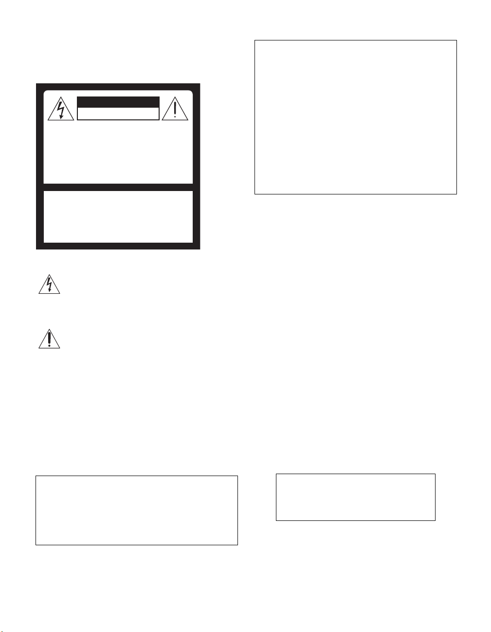
WARNING
To reduce the risk of fire or electric
shock, do not expose this apparatus to
rain or moisture.
CAUTION
RISK OF ELECTRIC SHOCK
DO NOT OPEN
ATTENTION
RISQUE DE CHOC ELECTRIQUE,
NE PAS OUVRIR
PRECAUCION
RIESGO DE CHOQUE ELECTRICO
NO ABRIR
CAUTION : TO REDUCE THE RISK OF ELECTRIC SHOCK,
DO NOT REMOVE COVER (OR BACK).
NO USER-SERVICEABLE PARTS INSIDE.
REFER SERVICING TO QUALIFIED SERVICE PERSONNEL.
This symbol is intended to alert the user to the
presence of uninsulated “dangerous voltage”
within the product’s enclosure that may be of
sufficient magnitude to constitute a risk of
electric shock to persons.
This symbol is intended to alert the user to the
presence of important operating and
maintenance (servicing) instructions in the
literature accompanying the appliance.
CAUTION
To prevent electric shock, do not use this polarized AC
plug with an extension cord, receptacle or other outlet
unless the blades can be fully inserted to prevent blade
exposure.
Note on Caption Vision
This television receiver provides display of television
closed captioning in accordance with §15.119 of the FCC
rules.
For Customers in the United States
If you have any questions about this product, you may
call:
QUALIA Customer Center
1-877-QUALIA3 (782-5423)
The number below is for FCC related matters only.
Declaration of Conformity
Trade Name: SONY
Model No.: MBD-Q005
Responsible Party: Sony Electronics Inc.
Address: 16450 W. Bernardo Dr.,
San Diego, CA 92127 U.S.A.
Telephone Number: 858-942-2230
This device complies with Part 15 of the FCC Rules.
Operation is subject to the following two conditions: (1)
This device may not cause harmful interference; and (2)
this device must accept any interference received,
including interference that may cause undesired
operation.
NOTIFICATION
This equipment has been tested and found to comply with
the limits for a Class B digital device, pursuant to Part 15
of the FCC Rules. These limits are designed to provide
reasonable protection against harmful interference in a
residential installation. This equipment generates, uses
and can radiate radio frequency energy and, if not
installed and used in accordance with the instructions,
may cause harmful interference to radio communications.
However, there is no guarantee that interference will not
occur in a particular installation. If this equipment does
cause harmful interference to radio or television
reception, which can be determined by turning the
equipment off and on, the user is encouraged to try to
correct the interference by one or more of the following
measures:
❑ Reorient or relocate the receiving antenna.
❑ Increase the separation between the equipment and
receiver.
❑ Connect the equipment into an outlet on a circuit
different from that to which the receiver is
connected.
❑ Consult the dealer or an experienced radio/TV
technician for help.
You are cautioned that any changes or
modifications not expressly approved in
this manual could void your warranty and
your authority to operate this equipment.
(Continued)
3
Page 6
For Customers in Canada
This Class B digital apparatus complies with Canadian
ICES-003.
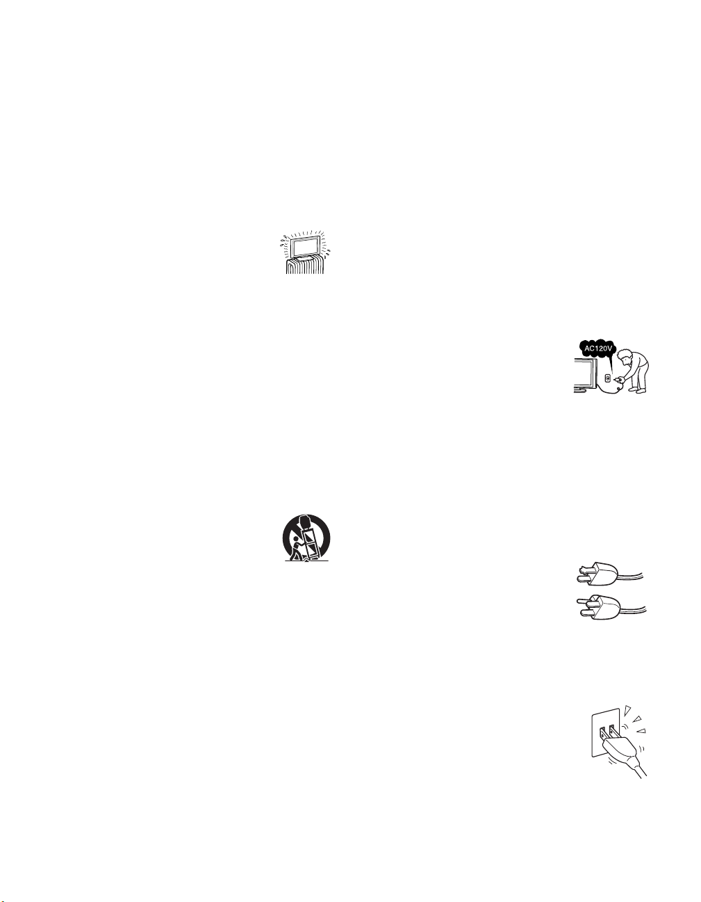
Safety
❑ Operate this TV only on 120 V AC.
❑ Use the AC power cord specified by Sony and
suitable for the voltage where you use it.
❑ The plug is designed, for safety purposes, to fit into
the wall outlet only one way. If you are unable to
insert the plug fully into the outlet, contact your
dealer.
❑ If any liquid or solid object should fall inside the
cabinet, unplug the TV immediately and have it
checked by qualified service personnel before
operating it further.
❑ If you will not be using the TV for several days,
disconnect the power by pulling the plug itself.
Never pull on the cord.
❑ For details concerning safety precautions, see
“Important Safeguards” on page 5.
Installing
❑ The TV should be installed near an easily accessible
power outlet.
❑ To prevent internal heat buildup, do not block the
ventilation slots.
❑ Do not install the TV in a hot or humid place, or in a
place subject to excessive dust or mechanical
vibration.
❑ Avoid operating the TV at temperature below 41°F
(5°C).
❑ If the TV is transported directly from a cold to a
warm location, or if the room temperature changes
suddenly, the picture may be blurred or show poor
color. In this case, please wait a few hours to let the
moisture evaporate before turning on the TV.
❑ To obtain the best picture, do not expose the screen
to direct illumination or direct sunlight. It is
recommended to use spot lighting directed down
from the ceiling or to cover the windows that face
the screen with opaque drapery. It is desirable to
install the TV in a room where the floor and walls
are not of a reflective material.
Note
This digital television is capable of receiving analog
basic, digital basic and digital premium cable television
programming by direct connection to a cable system
providing such programming. A security card provided
by your cable operator is required to view encrypted
digital programming. Certain advanced and interactive
digital cable services such as video-on-demand, a cable
operator’s enhanced program guide and data-enhanced
television services may require the use of a set-top box.
For more information call your local cable operator.
This television also includes a QAM demodulator which
should allow you to receive unscrambled digital cable
television programming via subscription service to a
cable service provider. Availability of digital cable
television programming in your area depends on the type
of programming and signal provided by your cable
service provider.
Trademark Information
CableCARD™ is a trademark of Cable Television
Laboratories, Inc.
TruSurround, SRS and the ( )® symbol are trademarks
of SRS Labs, Inc. TruSurround technology is
incorporated under license from SRS Labs, Inc.
BBE and BBE Symbol are trademarks of BBE Sound,
Inc. and are licensed by BBE Sound, Inc. under U.S.
Patent No. 4,638,258 and 4,482,866.
Macintosh is a trademark licensed to Apple Computer,
Inc., registered in the U.S.A and other countries.
Manufactured under license from
Dolby Laboratories. “Dolby” and the
double-D symbol are trademarks of
Dolby Laboratories.
This TV incorporates High-Definition
Multimedia Interface (HDMI
technology. HDMI, the HDMI logo and High-Definition
Multimedia Interface are trademarks or registered
trademarks of HDMI Licensing LLC.
WEGA, Steady Sound, Digital Reality Creation,
CineMotion, BN Smoother, Memory Stick, Memory
Stick Duo, Memory Stick PRO, Memory Stick PRO Duo,
MagicGate, MID and Twin View are trademarks of Sony
Corporation. i.LINK is a trademark of Sony Corporation
and used only to designate that a product contains an
IEEE 1394 connector. All products with an i.LINK
connector may not communicate with each other.
™
)
Caution
This TV for use only with Sony TABLE-TOP STAND
SU-XTQ005, WALL-MOUNT BRACKET SUXWQ005, and FLOOR STAND SU-XFQ005. Use with
other stand models may result in instability causing
possible injury.
4
Page 7
Important Safety Instructions
1) Read these instructions.
2) Keep these instructions.
3) Heed all warnings.
4) Follow all instructions.
5) Do not use this apparatus near water.
6) Clean only with dry cloth.
7) Do not block any ventilation slots. Install in
accordance with the manufacturer’s instructions.
8) Do not install near any heat sources
such as radiators, heat registers,
stoves, or other apparatus (including
amplifiers) that produce heat.
9) Do not defeat the safety purpose of the polarized or
grounding-type plug. A polarized plug has two
blades with one wider than the other. A grounding
type plug has two blades and a third grounding prong.
The wide blade or the third prong are provided for
your safety. If the provided plug does not fit into
your outlet, consult an electrician for replacement of
the obsolete outlet.
10) Protect the power cord from being walked on or
pinched particularly at plugs, convenience
receptacles, and the point where they exit from the
apparatus.
11) Only use attachments/accessories specified by the
manufacturer.
12) Use only with the cart, stand, tripod,
bracket, or table specified by the
manufacturer, or sold with the apparatus.
When a cart is used, use caution when
moving the cart/apparatus combination
to avoid injury from tip-over.
13) Unplug this apparatus during lightning storms or
when unused for long periods of time.
14) Refer all servicing to qualified service personnel.
Servicing is required when the apparatus has been
damaged in any way, such as power-supply cord or
plug is damaged, liquid has been spilled or objects
have fallen into the apparatus, the apparatus has been
exposed to rain or moisture, does not operate
normally, or has been dropped.
15) Apparatus shall not be exposed to dripping or
splashing and no objects filled with liquids, such as
vases, shall be placed on the apparatus.
Important
Safeguards
Before using your TV, please read these instructions
completely, and keep this manual for future reference.
Carefully observe and comply with all warnings, cautions
and instructions placed on the set or described in the
operating instructions or service manual.
WARNING
To guard against injury, the following basic safety
precautions should be observed in the installation, use
and servicing of the set.
Use
Power Sources
This set should be operated only from
the type of power source indicated on
the serial/model plate.
If you are not sure of the type of
electrical power supplied to your home,
consult your dealer or local power company.
Grounding or Polarization
This set is equipped with a polarized AC power cord plug
(a plug having one blade wider than the other), or with a
three-wire grounding type plug (a plug having a third pin
for grounding). Follow the instructions below:
For the set with a polarized AC power cord
plug
This plug will fit into the power outlet
only one way. This is a safety feature. If
you are unable to insert the plug fully
into the outlet, try reversing the plug.
If the plug still fails to fit, contact your
electrician to have a suitable outlet installed. Do not
defeat the safety purpose of the polarized plug by forcing
it in.
Wall outlet
Do not use a poor fitting outlet.
Insert the plug fully into the outlet. If it is
loose, it may cause arcing and result in fire.
Contact your electrician to have the outlet
changed.
Wiring
For your safety, unplug the AC power cord when wiring
cables.
(Continued)
5
Page 8

Electric shock
Do not touch the AC power cord or the
unit with a wet hand.
If you plug/unplug the AC power cord
from the unit with a wet hand, it may
cause electric shock.
Cleaning
❑ Clean the AC power plug regularly.
❑ If the plug is covered with dust and
it picks up moisture, its insulation
may deteriorate and result in fire.
Unplug the AC power plug and
clean it regularly.
❑ Unplug the AC power cord when cleaning this unit.
If not, it may result in electric shock.
❑ Clean the cabinet of the TV with
a dry soft cloth. To remove dust
from the screen, wipe it gently
with a soft cloth. Stubborn stains
may be removed with a cloth slightly dampened
with solution of mild soap and warm water. Never
use strong solvents such as thinner or benzine for
cleaning.
❑ If using a chemically pretreated cloth, please follow
the instruction provided on the package.
❑ If the picture becomes dark after using the TV for a
long period of time, it may be necessary to clean the
inside of the TV. Consult qualified service
personnel.
❑ Clean the rear cover area of the display unit and
both sides of the media receiver unit regularly. Dust
in these areas may cause a problem with the cooling
system of the TV set.
For the set with a three-wire grounding type
AC plug
This plug will only fit into a groundingtype power outlet. This is a safety
feature. If you are unable to insert the
plug into the outlet, contact your
electrician to have a suitable outlet
installed. Do not defeat the safety purpose of the
grounding plug.
Overloading
Do not overload wall outlets, extension
cords or convenience receptacles beyond
their capacity, since this can result in fire
or electric shock.
Power
Always turn the set off when it is not
being used. When the set is left
unattended and unused for long
periods of time, unplug it from the
wall outlet as a precaution against the possibility of an
internal malfunction that could create a fire hazard.
Sound
If a snapping or popping sound from a TV
set is continuous or frequent while the TV
is operating, unplug the TV and consult
your dealer or service technician. It is
normal for some TV sets to make occasional snapping or
popping sounds, particularly when being turned on or off.
AC power cord
If you damage the AC power cord, it may result in fire or
electric shock.
❑ Do not pinch, bend, or twist the cord excessively.
The core lines may be bared and cut, and cause
short-circuit, resulting in fire or electric shock.
❑ Do not convert or damage the AC power cord or
display interface cable.
❑ Do not put anything heavy on the AC power cord.
Do not pull the AC power cord.
❑ Keep the AC power cord away from heat sources.
❑ Be sure to grasp the plug when disconnecting the
AC power cord.
If the AC power cord is damaged, stop using it and ask
your dealer or Sony service center to exchange it.
Batteries
Do not dispose of batteries in fire.
Do not short circuit, disassemble or overheat the
batteries.
Dispose of used batteries
To preserve our environment, dispose the used batteries
according to your local laws or regulations.
Object and Liquid Entry
Never push objects of any kind into the
set through the cabinet slots as they may
touch dangerous voltage points or short
out parts that could result in a fire or
electric shock. Never spill liquid of any
kind on the set.
Do not place any objects on the unit.
The apparatus shall not be exposed to
dripping or splashing and that no objects
filled with liquids, such as vases, shall be
placed on the apparatus.
6
Page 9
Attachments
Do not use attachments not recommended
by the manufacturer, as they may cause
hazards.
Medical institution
Do not place this unit in a place where
medical equipment is in use.
It may cause malfunction of medical
instruments.
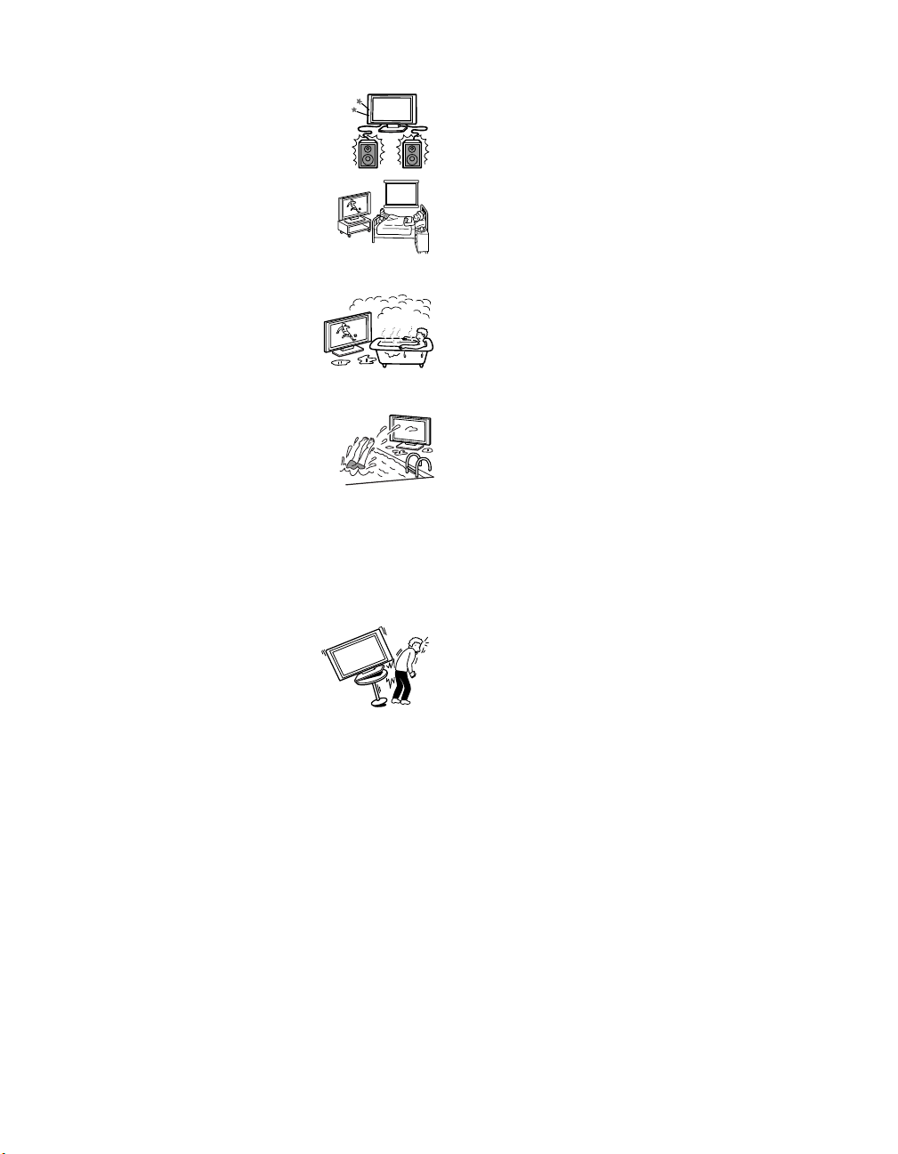
Moisture and flammable objects
❑ Do not use power-line operated
sets near water — for example,
near a bathtub, washbowl, kitchen
sink, or laundry tub, in a wet
basement, or near a swimming pool, etc. It may
result in fire or electric shock.
❑ Do not let this unit get wet. Never
spill liquid of any kind on the unit.
If any liquid or solid object does fall
through, do not operate the unit. It
may result in electric shock or
damage to the unit. Have it checked immediately by
qualified personnel.
❑ To prevent fire, keep inflammable objects or naked
lights (e.g. candles) away from the unit.
Accessories
Do not place the set on an unstable
cart, stand, table or shelf. The set may
fall, causing serious injury to a child or
an adult and serious damage to the set.
Use only a cart or stand recommended
by the manufacturer for the specific model of TV. An
appliance and cart combination should be moved with
care. Quick stops, excessive force, and uneven surfaces
may cause the appliance and cart combination to
overturn.
Broken pieces
Do not throw anything at the unit.
The screen glass may break by the impact and cause
serious injury.
Cable wiring
Take care not to catch your feet on the cables. It may
damage the unit.
Heat
Do not touch the surface of the TV.
It remains hot, even for some time after the TV is turned
off.
Volume adjustment
Adjust the volume so as not to trouble your neighbors.
Sound carries very easily at night time. Therefore, closing
the windows or using headphones is suggested.
When using headphones, adjust the volume so as to avoid
excessive levels, as hearing damage may result.
Disposal of the TV
❑ Do not dispose the TV with general household
waste.
❑ The LCD contains a small amount of liquid crystal.
Follow your local ordinances and regulations for
disposal.
Handling of broken glass and liquid crystal
leakage
If the LCD panel gets damaged, crystalline liquid leakage
may occur, or scattered broken glass may result. Do not
touch broken glass or crystalline liquid (which is toxic),
with bare hands as cuts or poisoning/skin irritation may
occur. Also, do not let glass fragments or leaked
crystalline liquid get into your eyes or mouth. Should
either contact your eyes or mouth, rinse the contacted
area thoroughly with water and consult your doctor.
LCD screen
❑ Although the LCD screen is made with high-
precision technology and has effective pixels of
99.99% or more, black dots may appear or bright
points of light (red, blue, or green) may appear
constantly on the LCD screen. This is a structural
property of the LCD panel and is not a malfunction.
❑ Do not expose the LCD screen surface to the sun.
Doing so may damage the screen surface.
❑ Do not push or scratch the front filter, or place
objects on top of the TV. The image may be uneven
or the LCD panel may be damaged.
❑ If the TV is used in a cold place, a smear may occur
in the picture or the picture may become dark. This
does not indicate a failure. These phenomena
improve as the temperature rises.
❑ Ghosting may occur when still pictures are
displayed continuously. It may disappear after a few
moments.
❑ The screen and cabinet get warm when the TV is in
use. This is not a malfunction.
❑ Avoid spraying insect repellent with volatile
material to the screen.
❑ Avoid prolonged contact with rubber or plastic made
material.
(Continued)
7
Page 10
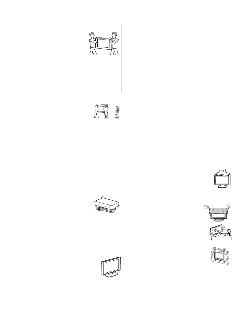
Installation and moving
Carry the TV in the specified manner
If you carry the TV in a manner other
than the specified manner and without
the specified number of persons, it
may drop and a serious injury may be
caused. Be sure to follow the
instructions mentioned below.
❑ Carry the TV with the specified number of persons
(see page 25).
❑ Hold the TV tightly when carrying it.
❑ Before carrying the TV, disconnect any accessories
or cables.
Installation
❑ When installing the display unit on
the wall, be sure to have assemblers
install and keep away from the unit.
If a person other than the assemblers
install the display unit on the wall using a wall
mount unit, the unit may fall and cause serious
injury if the unit is not installed securely.
❑ To prevent injury, this apparatus must be securely
attached to the stand/wall in accordance with the
installation instructions.
Placement for viewing
It is recommended to watch the TV at a distance of 3-7
times that of the screen, and in moderate brightness.
Watching the TV for too long or in a dark room will cause
eye fatigue.
Recommended place for the media receiver unit
Place the media receiver unit on a stable,
level surface. Otherwise, the media
receiver unit may fall and cause injury.
Use an optional Sony stand, which has
adequate strength.
Weight
Do not stand on the media receiver unit. The unit may fall
or break, causing injury. Pay special attention to little
children.
Optional accessories
Observe the following when installing the
TV using a stand or wall-mount bracket. If
the TV is not secured properly, it may fall
and cause injury.
❑ Be sure to follow the operating instructions supplied
with your stand or wall-mount bracket when
installing the unit.
❑ Be sure to attach the brackets supplied with your
stand or wall-mount bracket.
Protruding location
Do not install the TV in protruding locations. If you
install the unit in the following locations, injury may
result.
❑ Do not install the unit in a location where the unit
protrudes, such as pillars.
❑ Do not install the unit in a location that may cause
facial injury.
Oils
Do not install this unit in restaurants where oily vapors
occur. Dust absorbing oil may enter into the unit and
damage the unit.
Corrosion
Use of this set near the seashore may subject the set to
excessive salt, corrosion and internal damage and result
in deterioration of the set’s performance. If the set will be
subjected to these conditions, steps should be taken to
reduce the humidity and temperature of the area where
the set is located.
Ventilation
The slots and openings in the cabinet and in the back or
bottom are provided for necessary ventilation. To ensure
reliable operation of the set, and to protect it from
overheating, these slots and openings must never be
blocked or covered.
Unless proper ventilation is provided, the unit
may gather dust and get dirty. For proper
ventilation, observe the following:
❑ Do not install the unit turned backward or
sideways.
❑ Do not install the unit turned over or upside down.
❑ Never cover the slots and openings
with a cloth or other materials.
❑ Never block the slots and openings
by placing the set on a bed, sofa, rug
or other similar surface.
❑ Never place the set in a confined
space, such as a bookcase or built-in
cabinet, unless proper ventilation is
provided.
❑ Leave some space around the unit.
When installing the unit against a wall, keep it at
least 4 inches (10 cm) away from the wall.
Otherwise, adequate air circulation may be blocked,
causing overheating that may result in fire or
damage to the unit.
8
Page 11
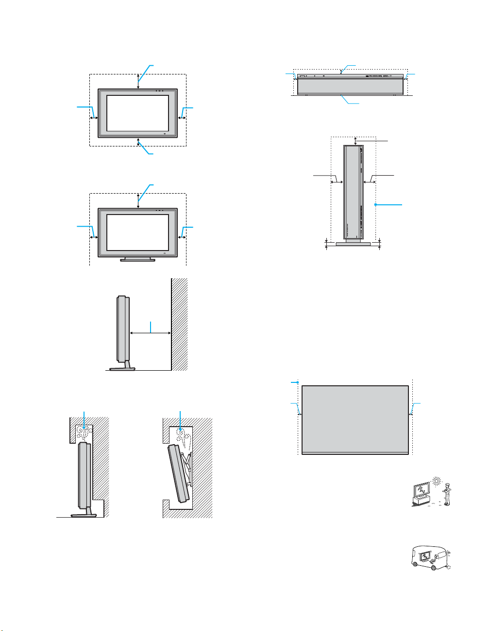
When installing the unit on the wall,
allow this much space.
11 7/8 inches (30 cm)
4 inches
(10 cm)
4 inches (10 cm)
When installing the unit using a stand,
allow this much space.
11 7/8 inches (30 cm)
4 inches
(10 cm)
6 inches
(15 cm)
4 inches
(10 cm)
4 inches
(10 cm)
Media receiver unit: Front view
7
/8 inches
2
2 inches
(5 cm)
(7 cm)
POWER
TIMER
STANDBY
POWER/STANDBY
MEDIA RE EIVER UNIT MBD-Q 0/5
13
inches
/32
(1 cm)
2 inches
QUALIA
(5 cm)
OPEN
Allow this
much
space.
When installing upright:
7
/8 inches
2
(7 cm)
2 inches
(5 cm)
13
/32 inches (1 cm)
2 inches
(5 cm)
Allow this
much
space.
13
/32 inches (1 cm)
Place the media receiver unit on a stable level surface so
as not to block the inlets at the bottom of the media
receiver unit.
Media receiver unit: Top view
Never place the media receiver unit in a confined space.
Make sure to provide sufficient space in front of the front
and back of the media receiver unit. Failure to do so may
cause overheating and result in fine or damage to the unit.
Ensure reliable operation of the unit by ensuring proper
ventilation of the exhaust fan.
Never install the unit as follows:
Air circulation is blocked.
Air circulation is
blocked.
Allow this
much
space.
2 inches
(5 cm)
Outdoor use
Do not install this unit outdoors. If the unit
is exposed to rain, it may result in fire or
electric shock. If the unit is exposed to direct
sunlight, the unit may heat up and it may
damage the unit.
Vehicle and ceiling
Do not install this unit in a vehicle or hung
from the ceiling.
Bumping of the vehicle may cause the set to
fall down and cause injury.
2 inches
(5 cm)
(Continued)
9
Page 12
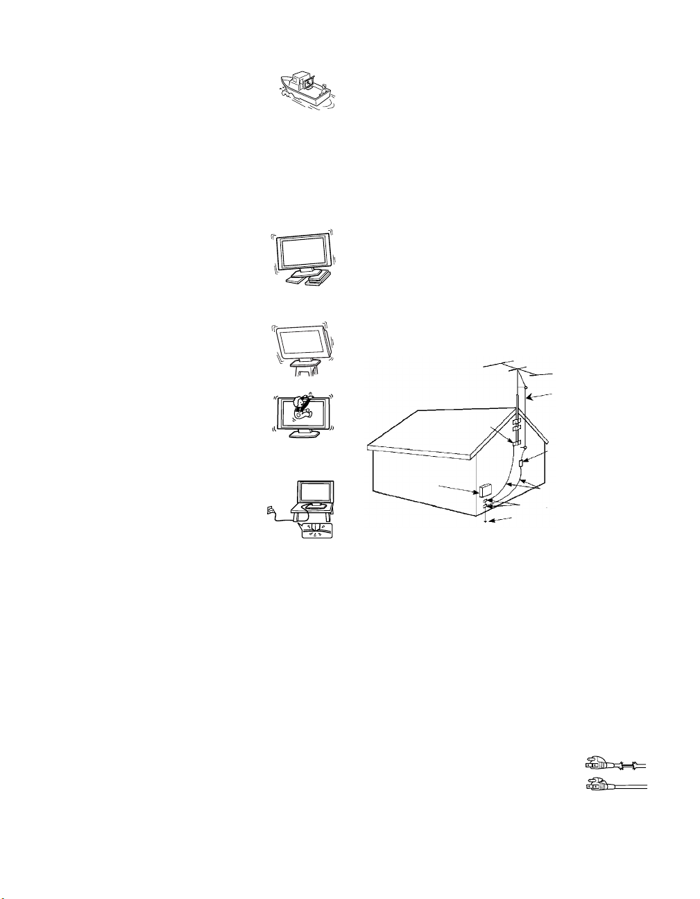
Ship and vessel
Do not install this unit in a ship or vessel. If
the unit is exposed to seawater, it may cause
fire or damage the unit.
Preventing the TV from toppling over
Take measures to prevent the unit from toppling over and
causing injury.
To prevent the unit from toppling over, secure the unit to
the wall or pillar.
Installing on a level surface
If you install the unit on an inclined
surface, the unit may fall or drop and cause
injury or damage.
Placing on a stable surface
If you place the unit on an unstable surface,
the unit may fall and cause injury or
damage.
WHEN INSTALLING AN OUTDOOR ANTENNA
SYSTEM, EXTREME CARE SHOULD BE TAKEN TO
KEEP FROM CONTACTING SUCH POWER LINES
OR CIRCUITS AS CONTACT WITH THEM IS
ALM O S T IN VARI A BLY FATAL .
Be sure the antenna system is grounded so as to provide
some protection against voltage surges and built-up static
charges.
Section 810 of the National Electrical Code (NEC) in
USA and Section 54 of the Canadian Electrical Code in
Canada provides information with respect to proper
grounding of the mast and supporting structure,
grounding of the lead-in wire to an antenna discharge
unit, size of grounding conductors, location of antenna
discharge unit, connection to grounding electrodes, and
requirements for the grounding electrode.
Antenna Grounding According to the NEC
Refer to section 54-300 of Canadian Electrical Code for
Antenna Grounding.
Fall
Do not hang anything on the unit.
The unit may fall from the stand or wallmount unit, causing damage or serious
injury.
AC power cord
Unplug the AC power cord when moving
the unit. Do not move the unit with the AC
power cord plugged in. It may damage the
AC power cord and result in fire or
electric shock.
Do not allow anything to rest on or roll over the power
cord, and do not place the unit where the power cord is
subject to wear or abuse.
Magnet influence
This TV contains a strong magnet in the speaker unit that
generates a magnetic influence. Keep any items
susceptible to magnetic influence away from the TV
speaker.
Antennas
Outdoor Antenna Grounding
If an outdoor antenna is installed, follow the precautions
below. An outdoor antenna system should not be located
in the vicinity of overhead power lines or other electric
light or power circuits, or where it can come in contact
with such power lines or circuits.
Antenna lead-in wire
Ground clamp
Antenna lead-in wire
Electrical
service
equipment
NEC: National
Electrical Code
(NEC Section 810-20)
Grounding conductors
(NEC section 810-21)
Ground clamps
Power service grounding
electrode system (NEC Ar t
250 Part H)
Lightning
For added protection for this television receiver during a
lightning storm, or when it is left unattended and unused
for long periods of time, unplug it from the wall outlet
and disconnect the antenna. This will prevent damage to
the receiver due to lightning and power-line surges.
Service
Damage requiring service
Unplug the set from the wall outlet and refer servicing to
qualified service personnel under the following
conditions:
❑ When the power cord or plug is
damaged or frayed.
❑ If liquid has been spilled into the set.
❑ If the surface of the TV cracks, do not touch it,
unplug the AC power cord.
Otherwise electric shock may result.
10
Page 13
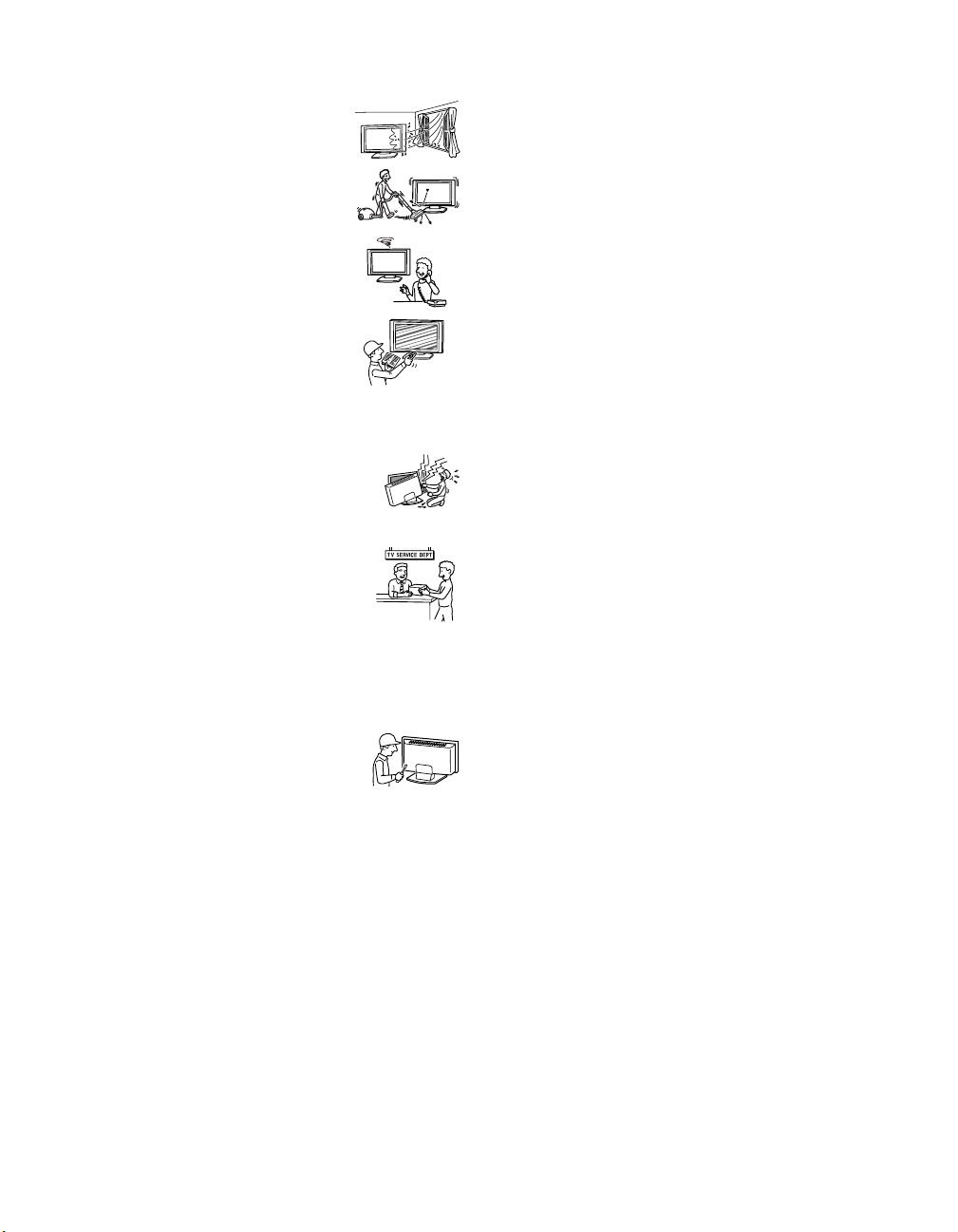
❑ If the set has been exposed to rain or water.
❑ If the set has been subject to
excessive shock by being dropped,
or the cabinet has been damaged.
❑ If the set does not operate normally
when following the operating
instructions. Adjust only those
controls that are specified in the
operating instructions. Improper
adjustment of other controls may
result in damage and will often
require extensive work by a
qualified technician to restore the
set to normal operation.
❑ When the set exhibits a distinct
change in performance, it indicates
a need for service.
Servicing
Do not attempt to service the set by yourself
since opening the cabinet may expose you to
dangerous voltage or other hazards.
Replacement parts
When replacement parts are required, be
sure the service technician certifies in
writing that he has used replacement parts
specified by the manufacturer that have the
same characteristics as the original parts.
Unauthorized substitutions may result in fire, electric
shock or other hazards.
Safety check
Upon completion of any service or repairs
to the set, ask the service technician to
perform routine safety checks (as specified
by the manufacturer) to determine that the
set is in safe operating condition, and to so certify. Ask a
qualified service technician to dispose of the set.
11
Page 14

Page 15

Contents
Introducing the Sony LCD TV
Presenting the Sony LCD TV ................................15
Package Contents...........................................15
Using This Manual.........................................15
Features..........................................................16
Setting Up the TV
Overview................................................................19
TV Controls and Connectors .................................20
Display Unit...................................................20
Media Receiver Unit .....................................21
Installing the TV ....................................................25
Carrying Your TV..........................................25
Take Precaution during the Installation.........26
To Prevent the TV from Falling ....................26
When Installing Your TV against a Wall ......26
Installing the Media Receiver Unit
Vertically .......................................................27
Connecting the TV.........................................28
Basic Connections: Connecting a Cable or
Antenna..........................................................30
Cable or Antenna ...........................................31
Cable and Antenna.........................................32
Cable Box and Antenna .................................33
Cable Box ......................................................34
Connecting Optional Equipment ...........................35
Making Video Connections ...........................36
About Using S VIDEO..................................36
VCR and Cable ..............................................37
VCR and Cable Box ......................................38
Two VCRs for Tape Editing..........................40
Satellite Receiver...........................................41
Satellite Receiver with a VCR and Cable......42
DVD Player with Component
Video Connectors ..........................................44
DVD Player with
S VIDEO and Audio Connectors...................45
Personal Computer.........................................46
Camcorder......................................................47
Audio Receiver ..............................................48
Sub Woofer....................................................49
Digital Cable Box ..........................................49
Digital Satellite Receiver...............................50
Digital Satellite Receiver with an HDMI
Connector.......................................................51
DVD Player or Digital Satellite Receiver via an
AV Receiver with CENTER SPEAKER IN
Terminals .......................................................53
Connecting a Device with an Optical IN
Connector.......................................................55
Using the CONTROL S Feature............................56
Using CableCARD ................................................57
About Using CableCARD .............................57
Activating CableCARD Service....................57
Removing the CableCARD ...........................58
Setting Up the TV Channel List ............................59
Using Initial Setup .........................................59
Using the Remote Control
Overview................................................................61
Inserting Batteries into the Remote Control ..........61
Button Descriptions ...............................................62
Programming the Remote Control.........................64
Manufacturer’s Codes............................................65
Using Other Equipment with Your TV Remote
Control ...........................................................66
Operating a VCR ...........................................66
Operating a Satellite Receiver .......................66
Operating a Cable Box...................................67
Operating a DVD Player................................67
Operating an MDP
(Laserdisc Player)..........................................67
Using the Features
Overview................................................................69
Watching TV .........................................................69
Using the Program Guide ......................................70
Displaying the Program Guide ......................70
Using the Guide Menu...................................71
Using the Program Options Menu.................71
Using Wide Screen Mode......................................72
Changing the Wide Screen Mode for 4:3 Source
(Standard definition source) ..........................72
Changing the Wide Screen Mode for 16:9
Source (High definition source).....................73
Using Twin View...................................................74
Displaying Twin Pictures ..............................74
Activating the Picture ....................................74
Changing the Picture Size..............................76
13
Page 16

Using Favorite Channels........................................77
Using the Channel Menu ...............................77
Using the Favorite Channels Guide...............78
Using the Freeze Function .....................................79
Using Picture Off...................................................80
Using the PC Input.................................................81
Displaying the PC Screen ..............................81
Using the Memory Stick Viewer
About Memory Stick .............................................83
Features..........................................................83
Memory Stick Compatibility.........................84
Memory Stick Functionality ..........................84
File Compatibility..........................................85
Trademark Information..................................85
Inserting and Removing a Memory Stick..............86
Inserting a Memory Stick ..............................86
Inserting the Memory Stick Duo ...................87
Removing a Memory Stick ............................88
Using the Memory Stick Index..............................89
Using the Memory Stick Index......................90
Viewing Photos......................................................91
Photo Controls ...............................................91
Photo Menu Bar Options ...............................92
Using Zoom and Pan......................................93
Using Rotate ..................................................93
Playing Movies ......................................................94
Movie Controls ..............................................94
Movie Menu Bar Options ..............................95
Memory Stick Index Menu Bar Options................96
Slide Show Menu Options.............................96
Contents Menu Options .................................97
Memory Stick Menu ......................................97
Notes on Using Memory Stick Media ...................98
About DCF File Names .................................98
Memory Stick Precautions.............................99
Using i.LINK
About i.LINK.......................................................101
Using i.LINK Cables ...................................101
Connecting i.LINK Devices ........................102
Selecting an i.LINK Device.................................104
Using the i.LINK Control Panel ..........................105
i.LINK Setup........................................................107
Using the Menus
Overview..............................................................109
Using the Video Menu.........................................110
Selecting Video Options ..............................110
Selecting PC Video Options........................113
Using the Audio Menu.........................................114
Selecting Audio Options..............................114
Selecting PC Audio Options........................116
Using the Screen Menu........................................117
Selecting Screen Options.............................117
Using the Channel Menu .....................................119
Selecting Channel Options ..........................119
Using the Parent Menu ........................................121
Selecting Parent Options..............................121
Viewing Blocked Programs.........................122
Selecting Custom Rating Options................123
Using the Setup Menu .........................................125
Selecting Setup Options...............................125
Programming Caption Vision......................126
Selecting PC Setup Options.........................127
Using the Applications Menu ..............................130
Selecting Applications Options ...................130
Other Information
Overview..............................................................133
Glossary ...............................................................134
Contacting Sony...................................................135
Troubleshooting...................................................135
Twin View ...................................................135
Remote Control............................................136
CableCARD.................................................136
Memory Stick ..............................................137
Video............................................................139
Audio ...........................................................140
Channels ......................................................141
General.........................................................141
Specifications.......................................................143
Optional Accessories...........................................145
Index
Index ....................................................................146
14
Page 17

Introducing the Sony LCD TV
Presenting the Sony LCD TV
Thank you for purchasing this high definition built-in Sony LCD TV.
This manual is for model KDX-46Q005.
Package Contents Along with your new LCD TV (Display Unit and Media Receiver Unit), the
packing box contains a remote control and two AA (R6) batteries. It also
contains cables and cords necessary for setup. See page 144 for the complete
list of packaging contents.
Using This Manual We recommend that you carefully review the contents of the following six
sections in the order shown to ensure that you fully understand the operation
of your new TV.
1 Setting Up the TV
This section guides you through your initial setup. It shows you how to
install your TV, to connect your new components and to connect the
antenna and cable.
2 Using the Remote Control
This section shows you how to begin using your new TV. It also shows
you how to use your remote control functions.
Introducing the Sony LCD TV
3 Using the Features
This section provides information on using the Program Guide, Wide
Screen Mode, Twin View, Favorite Channels and Freeze Function.
4 Using the Memory Stick Viewer
This section shows you how to use the Memory Stick Viewer to view
files that are stored on Memory Stick media, such as photographs and
movies.
5 Using i.LINK
This section explains how to use the i.LINK feature.
6 Using the Menus
This section teaches you how to access on-screen menus and adjust your
TV settings.
Instructions in this manual are written for the remote control. Similar
controls are also found on the TV console.
15
Page 18

Introducing the Sony LCD TV
Features Some of the features that you will enjoy with your new TV include:
❑ WEGA Engine
source by minimizing the signal deterioration caused by digital-toanalog conversion and stabilizing the signal processing. This engine
features unique Sony technology, including:
● The first step in the digital processing system, Composite
Component Processor (CCP-X), which enhances input signal-tonoise ratio by chroma decoder digital processing.
● DRC (Digital Reality Creation
Enables the digital mapping of any NTSC source (DVD, VHS,
DBS, Cable, etc.), to create a picture that is precise and finer in
detail, rivaling high definition resolution. Incoming HD signals
(1080i) are also bitmapped, utilizing Sony’s proprietary algorithm
to provide a crisp and clear picture.
● IFP (Image Format Processor): The Digital Texture Enhancer
function of this chip provides the optimal contrast by utilizing a
wide dynamic range. This chip also reduces signal noise, by using
an improved motion vector algorithm, while maintaining image
sharpness.
❑ Integrated HDTV: You can watch digital television programs and
enjoy the improved audio/video quality offered by these programs.
❑ S-master Full Digital Amplifier: Delivers superb clear dialog and
reproduces the original sound quality while minimizing any sound
fragmentation or jitter noise.
❑ BN Smoother
encoding and decoding process.
❑ CineMotion
CineMotion feature provides smoother picture movement when playing
back movies or other video sources on film.
❑ Twin View
with the ability to zoom in on one picture and listen to the program in
the selected window. You can watch pictures from two different sources
(1080i, 720p, 480p or 480i) simultaneously.
❑ Memory Stick Viewer: Allows you to view digital photos (JPEG) and
movies (MPEG1) from Memory Stick media on your TV screen.
❑ Parental Control: V-Chip technology allows parents to block
unsuitable programming from younger viewers.
❑ CableCARD
encrypted cable channels — without the need for a set-top box — that
will enable you to receive not only standard definition but also high
definition television. The CableCARD, which is provided by your cable
™
: Delivers superb picture quality from any video
®
) MultiFunction 2 circuitry:
™
: Reduces the block noise caused by digital video
®
: Using the reverse 3-2 pull down technology, the
®
: Twin View allows you to watch two programs side by side
™
slot: Provides cable subscribers with access to digitally
16
Page 19

Introducing the Sony LCD TV
TV company, is inserted into the TV’s rear panel CableCARD slot.
After the service is activated with your cable TV company, the card
replaces the need for a separate set-top box. (Check with your cable TV
company about CableCARD service details, limitations, pricing, and
availability. For more information about CableCARD in this manual,
see page 57.)
❑ Component Video Inputs: Offers the best video quality for DVD
(480p, 480i) and digital set-top box (1080i, 720p, 480p, 480i)
connections.
❑ S VIDEO Inputs: Provides a high-quality image from connected
equipment.
❑ Favorite Channel Preview: Allows you to preview up to sixteen
favorite channels without leaving the current channel.
❑ Wide Screen Mode: Allows you to watch 4:3 normal broadcasts in
wide screen mode (16:9 aspect ratio).
❑ Steady Sound
®
: Equalizes volume levels so there is consistent output
between programs and commercials.
❑ HDMI (High-Definition Multimedia Interface): Provides an
uncompressed, all-digital audio/video interface between this TV and
any HDMI-equipped audio/video component, such as a set-top box,
DVD player, and A/V receiver. HDMI supports enhanced, or highdefinition video, plus two-channel digital audio.
❑ i.LINK: Provides a secure digital interface to other digital home
entertainment devices.
i.LINK allows for the secure transfer of
copyright-protected high-definition content between these devices and
your TV.
❑ Light Sensor: Allows the picture brightness level to be optimized to
ambient light. The effect from the Light Sensor depends on the setting
of Picture Mode and Power Saving. The factory setting is Off.
Introducing the Sony LCD TV
17
Page 20

Page 21

Setting Up the TV
Overview
This chapter includes illustrated instructions for setting up your TV.
Top ic Page(s)
TV Controls and Connectors 20
Installing the TV 25
Basic Connections: Connecting a Cable or Antenna 30
Connecting Optional Equipment
Making Video Connections
About Using S VIDEO
VCR and Cable
VCR and Cable Box
Two VCRs for Tape Editing
Satellite Receiver
Satellite Receiver with a VCR and Cable
DVD Player with Component Video Connectors
DVD Player with S VIDEO and Audio Connectors
Personal Computer
Camcorder
Audio Receiver
Sub Woofer
Digital Cable Box
Digital Satellite Receiver
Digital Satellite Receiver with an HDMI Connector
DVD Player or Digital Satellite Receiver via an AV Receiver with
CENTER SPEAKER IN Terminals
Connecting a Device with an Optical IN Connector 55
Using the CONTROL S Feature 56
Using CableCARD 57
Setting Up the TV Channel List 59
Setting Up the TV
35
36
36
37
38
40
41
42
44
45
46
47
48
49
49
50
51
53
19
Page 22
Setting Up the TV
TV Controls and Connectors
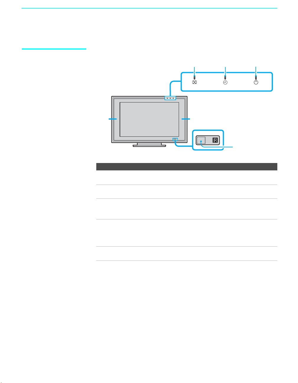
Display Unit
Front Panel
11
Item Description
1 Speakers
(Left/Right)
2 PICTURE OFF
LED
3 TIMER LED When lit, indicates one of the timers is set. When the
4 POWER ON/
STANDBY LED
5 (IR) Infrared
Receiver
2
3
4
POWER ON/STANDBYTIMERPICTURE OFF
5
Output audio signal.
When lit, indicates that the Picture Off feature is
activated. For details, see page 80.
timer is set, this LED will remain lit even if the TV set is
turned off. For details, see page 130.
Lights up in green when the TV set is turned on. The LED
lights up in red when in standby mode. If the LED blinks
in red continuously, this may indicate the media receiver
unit needs servicing (see “Contacting Sony” on page 135).
Receives IR signals from the remote control.
20
Page 23
2
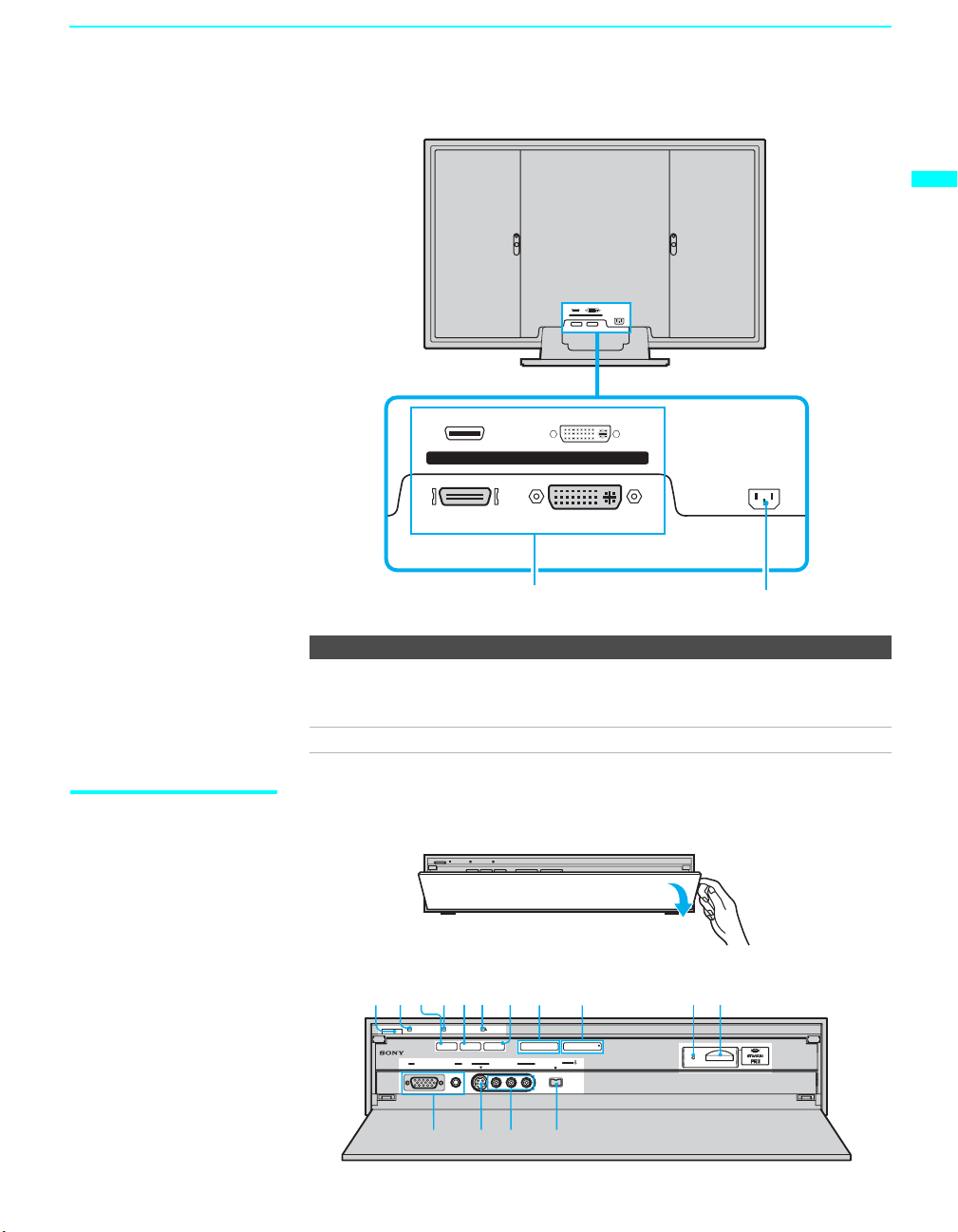
Rear Panel
Setting Up the TV
Setting Up the TV
WHITE
BLACK
DISPLAY SIGNAL IN
AC IN
Media Receiver Unit
BLACK
WHITE
DISPLAY SIGNAL IN
AC IN
1
Item Description
1 DISPLAY
SIGNAL IN
2 AC IN Connects the supplied AC power cord.
To open the front panel of the media receiver unit:
Connect to the DISPLAY SIGNAL OUT jacks on the rear
of the media receiver unit by using the supplied display
interface cable.
Front Panel
123 56740
POWER
POWER/STANDBY TIMER STANDBY
PC i.LINK TV/VIDEO - VOL + - CH +
VIDEO 8 (PC) IN
AUDIO
RGB
S VIDEO VIDEO
VIDEO 2 IN
L(MONO)-AUDIO-R
89
i.LINK
(
)
HDV/DV/TS/MICROMV
S400
qa
qsqdqg qf
(Continued)
21
Page 24

Setting Up the TV
z
The CH + button has a
tactile dot. Use the
tactile as a reference
when operating the TV.
Item Description
1 Main POWER Press to turn on and off the main power of the TV set.
2 POWER/
STANDBY LED
3 PC button Press to display the screen of the connected PC. For details,
4 TIMER LED When lit, indicates a timer is set. When the timer is set, this
5 i.LINK button Press to display the i.LINK Control Panel. For details, see
6 i.LINK
STANDBY LED
7 TV/VIDEO Press to select between the TV's tuner and other video
8 – VOL + Press to adjust the volume.
9 – CH + Press to scan through channels. To scan quickly through
0 Memory Stick
indicator
qa Memory Stick
slot
qs i.LINK Connect to the i.LINK jack on your i.LINK-compatible
qd VIDEO 2 IN
VIDEO/
L (MONO)AUDIO-R
qf VIDEO 2 IN
S VIDEO
qg VIDEO 8 (PC) IN Connect to the video output connector and audio output
Lights up in green when the TV set is turned on. The LED
lights up in red when in standby mode. If the LED blinks in
red continuously, this may indicate the media receiver unit
needs servicing (see “Contacting Sony” on page 135).
see page 81.
LED will remain lit even if the TV set is turned off. For
details, see page 130.
page 105.
When lit in red, indicates the i.LINK Standby is on. For
details, see page 126.
equipment inputs.
channels, press and hold down either CH - or +.
When lit, indicates that the Memory Stick is being read.
(Do not remove the Memory Stick when the indicator is lit.)
Memory Stick insertion slot. For details, see “Inserting and
Removing a Memory Stick” on page 86.
portable device. Provides a secure digital connection
between your TV and your i.LINK-compatible portable
device.
Connect to the composite A/V output jacks on your
camcorder or other video equipment.
Connect to the S VIDEO OUT jack on your camcorder or
other video equipment that has S VIDEO. Provides better
picture quality than composite video (qd).
jack on your personal computer. For details, see page 46.
22
Page 25
Setting Up the TV
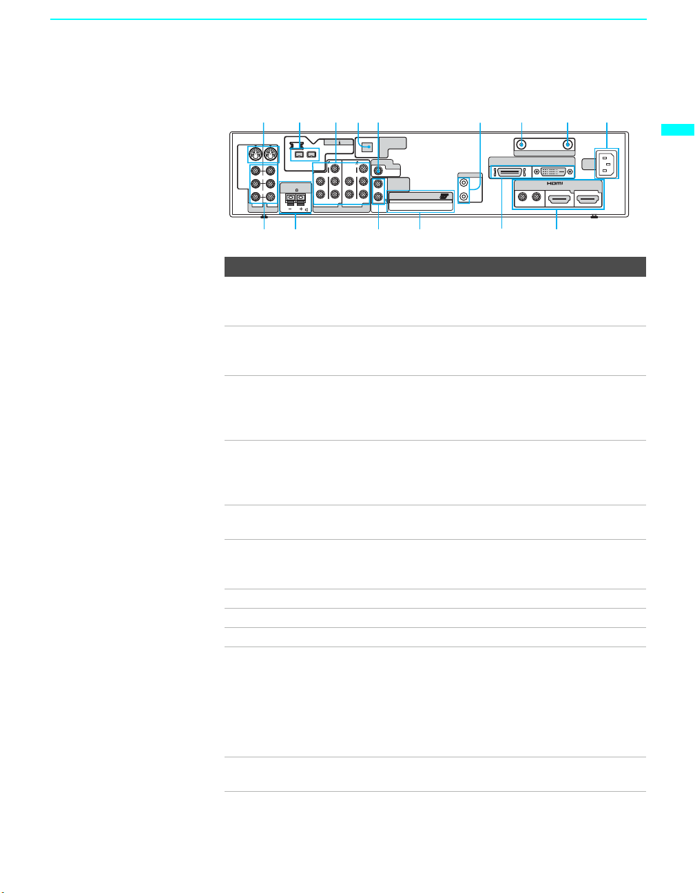
Rear Panel
135 642 978
S VIDEO
VIDEO
AUDIO
L (MONO)
CENTER SPEAKER IN
180W(6 ) MAX
R
1
345
VIDEO IN
i.LINK
(HDV/DV/TS/
MICROMV)
VIDEO VIDEO
Y
L
P
B
P
R
R
AUDIO
HD/DVD IN(1080i/720p/480p/480i)
DIGITAL AUDIO
S400
(OPTICAL)OUT
SUBWOOFER
Y
L
R
OUT(VAR)
P
B
L
AUDIO OUT
(VAR/FIX)
Cable CARD
R
P
R
AUDIO
CONTROL S
IN
OUT
TM
VHF/UHF
DISPLAY SIGNAL OUT
BLACK WHITE
AUDIO
RL
CABLE
AC
IN
IN
67
Setting Up the TV
qf qs 0
qdqg
qa
Connection Description
1 VIDEO 1/3 IN
S VIDEO
Connect to the S VIDEO OUT jack of your VCR or other
video equipment that has S VIDEO. S VIDEO provides
better picture quality than composite video (qg).
2 i.LINK Used for connecting i.LINK-equipped devices. These
terminals are not intended for connection with personal
computers.
3 HD/DVD 4 /5 IN
(1080i/720p/480p/
480i)
Connect to your DVD player’s or digital set-top box’s
component video (YP
BPR) and audio (L/R) jacks.
Component video provides better picture quality than the S
VIDEO (1) or the composite video (qg) connections.
4 DIGITAL AUDIO
(OPTICAL) OUT
Connects to the optical audio input of a digital audio
component that is PCM/Dolby Digital compatible.
(PCM/DOLBY*
DIGITAL)
5 SUB WOOFER
Connects to the input jack of your sub woofer.
OUT (VAR)
6 CONTROL S IN/
OUT
Allow the TV to receive (IN) and send (OUT) remote
control signals to other Sony infrared-controlled audio or
video equipment that has the CONTROL S function.
7 VHF/UHF RF input that connects to your VHF/UHF antenna.
8 CABLE RF input that connects to your cable signal.
9 AC IN Connects the supplied AC power cord.
q; VIDEO 6 IN and
VIDEO 7 IN HDMI
IN/R-AUDIO-L
HDMI (High-Definition Multimedia Interface) provides an
uncompressed, all-digital audio/video interface between
this TV and any HDMI-equipped audio/video component,
such as a set-top box, DVD player, and A/V receiver.
HDMI supports enhanced, or high-definition video, plus
two-channel digital audio. You can also connect a DVIequipped device to your TV by using an HDMI-DVI cable.
qa DISPLAY SIGNAL
OUT
Connect to the DISPLAY SIGNAL IN jacks of the display
unit by using the supplied display interface cable.
(Continued)
23
Page 26

Setting Up the TV
Connection Description
qs CableCARD slot CableCARD provides cable subscribers with access to
secure, digitally encrypted cable channels -- without the
need for a set-top box -- that will enable you to receive not
only standard definition but also high definition television.
For more information, see page 57.
qd AUDIO OUT (VAR/
FIX) L/R
qf CENTER
SPEAKER IN
180W (6Ω) MAX
qg VIDEO 1/3 IN
VIDEO/L(MONO)AUDIO-R
* Manufactured under license from Dolby Laboratories. “Dolby” and the double-D
symbol are trademarks of Dolby Laboratories.
Connect to the left and right audio input jacks of your audio
or video equipment. You can use these outputs to listen to
your TV’s audio through your stereo system.
Connect the center output terminals of Dolby Pro Logic*
system decoder amplifier. You can use the TV speakers as a
center speaker.
Connect to the composite A/V output jacks on your VCR or
other video component. A third composite A/V input jack
(VIDEO 2) is located on the front panel of the media
receiver unit.
24
Page 27
Installing the TV
Setting Up the TV
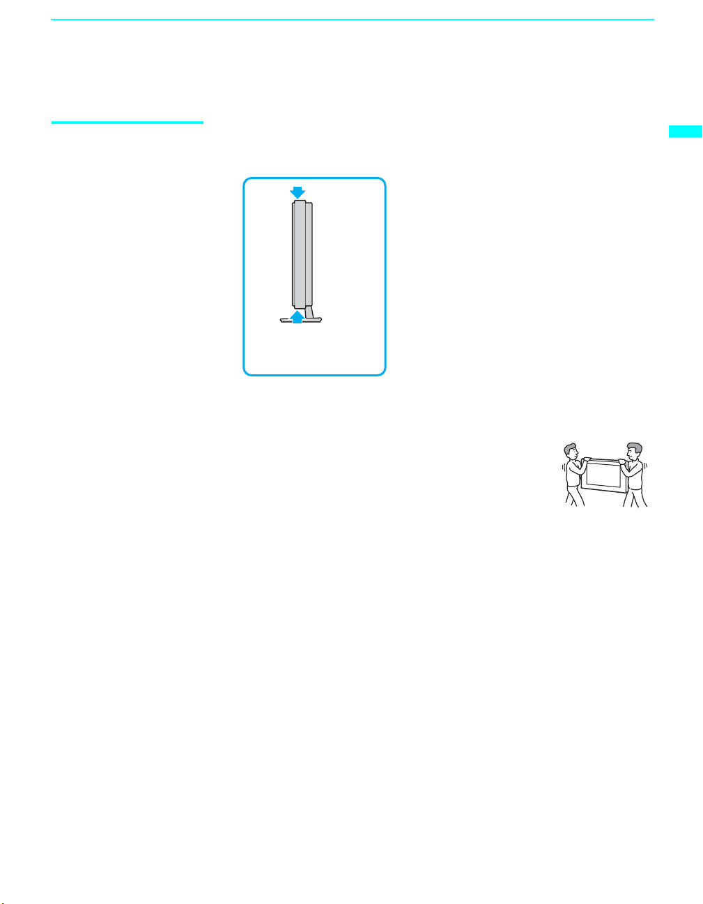
Carrying Your TV Carrying this TV requires at least two people. Do not hold by the pedestal or
the Front Panel Cover of the TV. Doing so may cause these parts to break off.
To carry the TV, hold it by
the top and bottom of the
panel.
If you carry the TV in a manner other than specified here, it may drop and a
serious injury may result. Be sure to follow the instructions given below.
❑ Carry the TV with at least two persons.
❑ Carry the TV holding the upper and bottom frames of
the TV as illustrated. Do not carry it holding the
speaker units.
❑ Hold the TV securely when carrying it.
❑ As the glass surface of the display unit has a special coating, avoid
touching the glass surface as much as possible.
Setting Up the TV
25
Page 28
Setting Up the TV
Take Precaution during the Installation
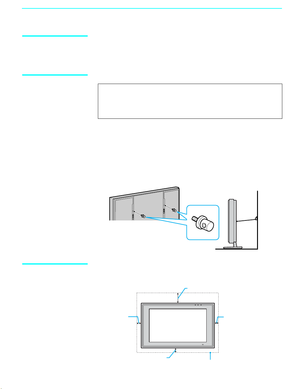
To Prevent the TV from Falling
To ensure the safety of children and the TV, keep children away from the TV
during installation. Climbing on or pushing the TV or its stand may cause it
to fall.
WARNING
Be sure to take measures to prevent the stand from toppling over.
If you fail to do so, the TV may topple over and cause injury. Anchor the
TV to a wall, pillar, etc., to prevent it from toppling over.
Prepare a commercially available strong rope or chain and wall anchor
bracket beforehand.
❑ After all the necessary connections including other equipment are
completed, be sure to attach a sturdy strong rope or chain securely to
each clamp screw (not supplied), and attach it to a wall or pillar. (The
clamp screw is supplied with the optional Table-Top Stand or Floor
Stand.)
Rear of Display Unit
Clamp screw
When Installing Your TV against a Wall
26
Keep your TV at least 4 inches (10 cm) away from the wall to provide proper
ventilation.
When installing the unit on the wall:
4 inches
(10 cm)
4 inches (10 cm)
7
11
/8 inches (30 cm)
4 inches
(10 cm)
Allow at least this much space
Page 29
Setting Up the TV
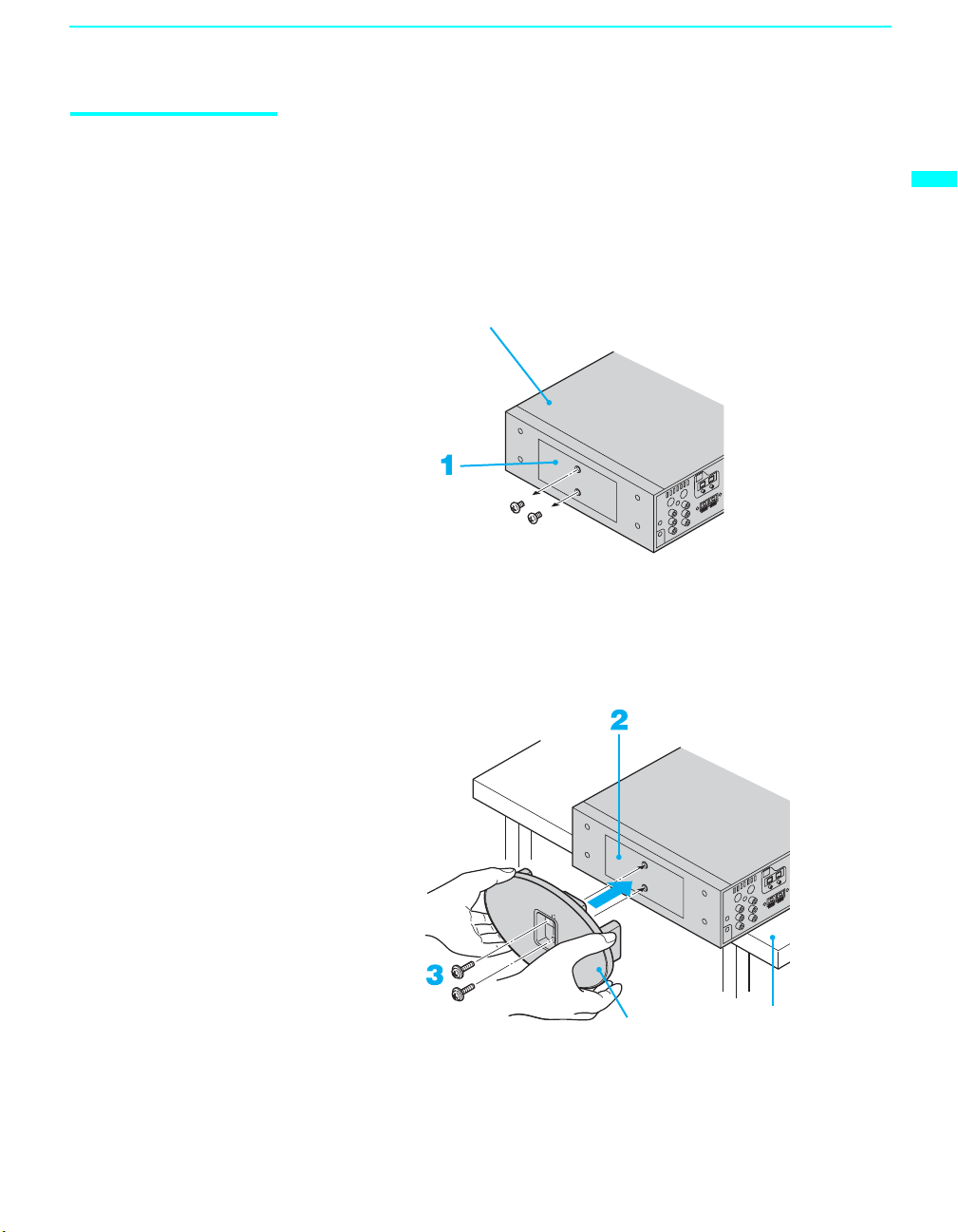
Installing the Media Receiver Unit Ver ti cally
When you install the media receiver unit vertically, use the supplied stand for
vertical installation. Attach the stand to the right side of the media receiver
unit. When you attach the stand, use the edge of a desk or a table, as shown
below.
1 Remove the two small screws from the right side of the media receiver
unit.
Media receiver unit
2 Match the two screw holes on the stand to those on the media receiver
unit.
3 Insert the two screws with washers (supplied) into the holes and tighten
them securely.
Setting Up the TV
Vertical installation stand
Desk or table
27
Page 30
Setting Up the TV
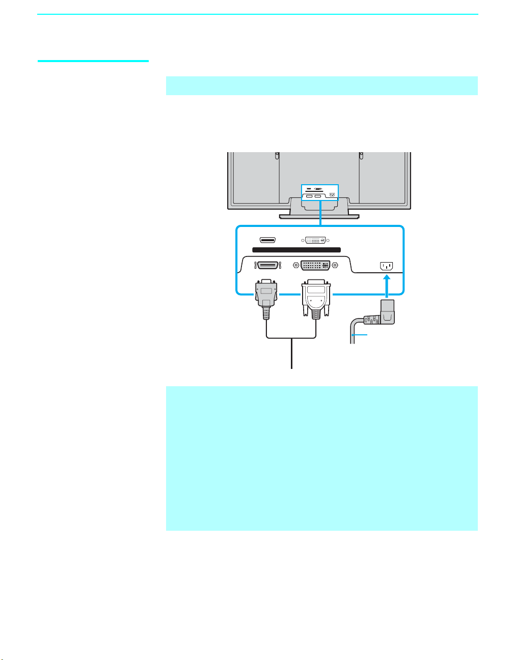
Connecting the TV
✍ Disconnect all power sources before making any connections.
1 Connect the display interface cable (supplied or VMC-X10 as an
optional accessary) to the DISPLAY SIGNAL IN jacks, and the AC
power cord (supplied) to the AC IN jack of the unit.
WHITE
BLACK
DISPLAY SIGNAL IN
AC IN
BLACK
DISPLAY SIGNAL IN
Display interface
cable (supplied or
VMC-X10 as an
optional accessory)
WHITE
Tighten the
screw slowly
until the screw
is stabilized.
AC IN
AC power cord
(supplied)
✍ Do not tighten the screws too much. It may damage the screws.
✍ Insert the connector until you hear a click. (Both sides of the connector
should be held securely by the clips.)
After connecting, make sure the connectors are firmly plugged in and
can not easily be pulled out.
✍ Refer to the optional accessory’s instruction manual for proper cable
installation.
✍ If you wish to install the media receiver unit and the display unit away
from each other, use an optional display cable, VMC-X10, which allows
you to place the two units up to 10 meters away from each other.
28
2 Secure the AC plug holder to the display’s AC IN jack.
Page 31

Setting Up the TV
AC power cord
(supplied)
AC plug
holder
(supplied)
AC IN (power supply
input) jack on the display
2 Clip on to the AC IN
jack until you hear
clicking.
1 Attach the AC plug holder
to the AC power cord.
✍ When you unplug the AC power cord, drag the holder down by pushing
both sides of the holder, then pull out the plug.
3 Install the display unit using an optional stand or rack unit.
For details, refer to the operating instructions supplied with your stand
or rack unit.
4 Connect the other end of the display interface cable to the media
receiver unit’s DISPLAY SIGNAL OUT jacks, and connect the AC
power cord to the media receiver unit’s AC IN jack.
S400
VIDEO VIDEO
L
R
AUDIO
DIGITAL AUDIO
(OPTICAL)OUT
SUBWOOFER
Y
OUT(VAR)
P
B
L
AUDIO OUT
(VAR/FIX)
R
P
R
Cable CARD
CONTROL S
TM
IN
OUT
VHF/UHF
DISPLAY SIGNAL OUT
BLACK WHITE
AUDIO
RL
CABLE
AC
IN
IN
67
AC power
cord
(supplied)
CENTER SPEAKER IN
180W(6 ) MAX
i.LINK
(HDV/DV/TS/
MICROMV)
Y
L
P
B
P
R
R
AUDIO
HD/DVD IN(1080i/720p/480p/480i)
S VIDEO
VIDEO
AUDIO
L (MONO)
R
1
345
VIDEO IN
Tighten the screw slowly until the
screw is stabilized.
Setting Up the TV
Display interface cable (supplied or
VMC-X10 as an optional accessory)
5 After making all connections, connect the AC power cords to wall
outlets.
✍ Be sure to use the supplied AC power cords.
✍ When connecting equipment, do not connect the AC power cords to wall
outlets until you have completed making all connections.
✍ Do not tighten the screws too much. It may damage the screws.
✍ Do not use damaged cables, such as cables with deformed connectors.
✍ This unit may fall and cause injury if accidently knocked or pulled by the
connected cable. Handle the display interface cable with care.
29
Page 32

Setting Up the TV
Basic Connections: Connecting a Cable or Antenna
The way in which you connect your TV will vary, depending on how your
home receives a signal (cable box and/or antenna) and whether or not you
plan to connect a VCR.
If You Are Connecting See Page
Cable or Antenna
❏ No cable box or VCR
Cable and Antenna
❏ No cable box or VCR
Cable Box and Antenna
❏ Cable box unscrambles only some channels (usually
premium channels)
❏ No VCR
Cable Box
❏ Cable box unscrambles all channels
❏ No VCR
If you are connecting a VCR
See the connections described on pages 37 and 38.
❑
31
32
33
34
30
Page 33

Setting Up the TV
Cable or Antenna For best results, use one of the following connections if you are
connecting a cable or an antenna and you:
❑ Do not need a cable box to unscramble channels. (If you have a cable
box, see pages 33 and 34.)
❑ Do not intend to connect a VCR. (If you have a VCR, see pages 37 and
38.)
The connection you choose depends on the cable type you have in your
home, as described below.
75-ohm coaxial cable (usually found in newer homes)
Cable Type Connect As Shown
VHF Only or
combined
VHF/UHF
75-ohm coaxial
cable
VHF/UHF
Rear of Media
Receiver Unit
Setting Up the TV
Cable
75-ohm coaxial
cable
CABLE
Rear of Media
Receiver Unit
300-ohm twin lead cable (usually found in older homes)
Cable Type Connect As Shown
VHF Only or
UHF Only or
combined
VHF/UHF
300-ohm twin lead cable
Antenna connector
(not supplied)
Rear of Media Receiver Unit
VHF/UHF
75-ohm coaxial and 300-ohm twin lead cable (found in some homes)
Cable Type Connect As Shown
VHF and UHF
75-ohm coaxial cable
Rear of Media
Receiver Unit
VHF/UHF
300-ohm twin lead cable
U/V mixer
(not supplied)
31
Page 34

Setting Up the TV
Cable and Antenna For best results, use this connection if you:
❑
Have a cable and an antenna.
(This is convenient if you are using a separate rooftop antenna to receive
additional channels that are not provided by your cable TV company.)
❑ Do not have a cable box or VCR. (If you have a cable box, see pages 33
and 34. If you have a VCR, see pages 37 and 38.)
Antenna and CATV cable
Cable Type Connect As Shown
Cable TV
(CATV) and
Antenna
Notes on Using This Connection
To Do This ... Do This ...
the Media Receiver
Switch
Unit’s input between the cable
and antenna
Antenna cable
Press ANT to switch back and forth between the
Media Receiver Unit’s VHF/UHF and CABLE
inputs.
CATV cable
32
✍ For optimum picture quality, a 75-ohm coaxial cable antenna connection
is highly recommended. Radio waves and other interference can easily
affect a 300-ohm twin lead cable, resulting in signal deterioration. If you
use a 300-ohm twin lead cable, keep it as far away as possible from the
TV.
✍ Do not use an indoor antenna, which is especially susceptible to radio
noise.
Page 35

Setting Up the TV
Cable Box and Antenna
Before connecting a cable
box, see “Using
CableCARD” on page 57.
For best results, use this connection if:
❑
Your cable company scrambles some channels, such as premium
channels (which requires you to use a cable box), but does not scramble
all channels.
❑ You do not have a VCR. (If you have a VCR, see pages 37 and 38.)
With this connection you can:
❑
Use the TV’s remote control to change channels coming through the
cable box to the Media Receiver Unit’s cable input. (You must first
program the remote control for your specific cable box; see
“Programming the Remote Control” on page 64.)
❑ Use the TV’s remote control to change channels coming directly into
the Media Receiver Unit’s VHF/UHF input jack.
CATV cable
Antenna Cable
IN OUT
Cable box
VHF/UHF
Rear of Media Receiver Unit
Coaxial
cable
CABLE
✍ This connection will allow you to take advantage of dual picture features
such as Twin View, Freeze, etc.
Setting Up the TV
Notes on Using This Connection
To Do This ... Do This ...
Use the cable box Tune the TV to the channel the cable box is set to (usually channel 3
or 4) and then use the cable box to switch channels.
Set up the TV remote control to operate the cable
box
Activate the remote control to operate the cable
box
Program the remote control. See “Programming the Remote
Control” on page 64.
Press FUNCTION repeatedly until the SAT/CABLE indicator lights
up.
Prevent the accidental switching of TV channels When using the cable box, the TV must stay on the channel the cable
box is set to (usually channel 3 or 4). You can use the TV’s Channel
Fix feature to lock in a specific channel. For details, see “Using the
Channel Menu” on page 119.
the TV’s input between the cable box and
Switch
cable
Press ANT to switch back and forth between the TV’s VHF/UHF
(scrambled channels) and CABLE (unscrambled) inputs.
33
Page 36

Setting Up the TV
Cable Box For best results, use this connection if:
❑
Your cable company scrambles all channels, which requires you to use a
Before connecting a cable
box, see “Using
CableCARD” on page 57.
cable box.
❑ You do not have a VCR. (If you have a VCR, see pages 37 and 38.)
With this connection you can:
❑
Use the TV’s remote control to change channels coming through the
cable box to the TV’s VHF/UHF jack. (You must first program the
remote control for your specific cable box.)
✍ With this connection, all channels come into the TV through your cable
box and only one unscrambled signal is sent to the TV, so you cannot
use the dual picture features. If some of your channels are scrambled,
but others are not, consider using the “Cable Box and Antenna”
connection on page 33 instead.
To connect the cable box
1 Connect the CATV cable to the cable box’s input jack.
2 Use a coaxial cable to connect the cable box’s output jack to the TV’s
VHF/UHF jack.
3 Run Auto Program, as described in “Setting Up the TV Channel List”
on page 59.
CATV cable
Coaxial cable
VHF/UHF
Rear of Media Receiver Unit
IN
Cable box
Notes on Using This Connection
To do this... Do This ...
Use the cable box Tune the TV to the channel the cable box is set to (usually channel 3
or 4) and then use the cable box to switch channels.
Set up the TV remote control to operate the cable
box
Activate the remote control to operate the cable
box
Prevent the accidental switching of TV channels When using the cable box, the TV must stay on the channel the cable
Program the remote control. See “Programming the Remote
Control” on page 64.
Press FUNCTION repeatedly until the SAT/CABLE indicator lights
up.
box is set to (usually channel 3 or 4). You can use the TV’s Channel
Fix feature to lock in a specific channel. For details, see “Using the
Channel Menu” on page 119.
OUT
34
Page 37

Connecting Optional Equipment
Use the directions in this section to connect the following optional
equipment:
If You Are Connecting See Page
Making Video Connections 36
About Using S VIDEO 36
VCR and Cable 37
VCR and Cable Box 38
Two VCRs for Tape Editing 40
Satellite Receiver 41
Satellite Receiver with a VCR and Cable 42
DVD Player with Component Video Connectors 44
DVD Player with S VIDEO and Audio Connectors 45
Personal Computer 46
Camcorder 47
Audio Receiver 48
Sub Woofer 49
Digital Cable Box 49
Digital Satellite Receiver 50
Digital Satellite Receiver with an HDMI Connector 51
DVD Player or Digital Satellite Receiver via an AV Receiver
with CENTER SPEAKER IN Terminals
Connecting a Device with an Optical IN Connector 55
Using the CONTROL S Feature 56
Using CableCARD 57
Setting Up the TV
Setting Up the TV
53
35
Page 38

Setting Up the TV
Making Video Connections
About Using
S VIDEO
Your TV includes several types of video inputs. When connecting your TV,
use the inputs that are available on your components that provide the best
video performance, as described below.
Separate audio
connection required
No
Best Video
Performance
Connector Type
HDMI (High-Definition
Multimedia Interface)
Component video Yes
S VIDEO
L-AUDIO-R
Composite video
RF/Coaxial No
If the optional equipment you are connecting has an S VIDEO jack
(shown at left), you can use an S VIDEO cable for improved picture
quality (compared to an A/V cable). Because S VIDEO carries only
the video signal, you also need to connect audio cables for sound, as
shown below.
36
Example of an S VIDEO Connection
S VIDEO cable
Equipment with S VIDEO
Rear of Media Receiver Unit
S VIDEO
VIDEO
AUDIO
1 3
Audio cable
L (MONO)
R
VIDEO IN
Cables are often
color-coded to connectors.
Connect red to red,
white to white, etc.
Page 39

VCR and Cable Use this hookup if:
❑ You have cable TV that does not require a cable box.
Disconnect all power sources before making any connections.
1 Connect the CATV cable to the single (input) jack of the splitter.
2 Using a coaxial cable, connect one of the output jack of the splitter to
the TV’s CABLE jack.
3 Using a coaxial cable, connect the splitter's other output jack to the
VCR's input jack.
4 Using A/V and S VIDEO cables, connect the VCR’s AUDIO and
S VIDEO OUT jacks to the TV’s AUDIO and S VIDEO IN jacks.
✍ If your VCR is not equipped with S VIDEO, use a VIDEO cable (yellow)
instead of the S VIDEO cable.
Rear of Media Receiver Unit
Setting Up the TV
Setting Up the TV
S VIDEO
S VIDEO
VIDEO
AUDIO
L (MONO)
1 3
VIDEO IN
R
CENTER SPEAKER IN
180W(6 ) MAX
VIDEO
AUDIO-L
AUDIO-R
S VIDEO cable
i.LINK
S400
(HDV/DV/TS/
MICROMV)
VIDEO VIDEO
Y
L
P
B
P
R
R
AUDIO
45
Y
P
B
P
R
L
R
AUDIO
HD/DVD IN(1080i/720p/480p/480i)
A/V cable
SUBWOOFER
VCR
DIGITAL AUDIO
(OPTICAL)OUT
OUT(VAR)
L
AUDIO OUT
(VAR/FIX)
R
Cable CARD
VHF/UHF
DISPLAY SIGNAL OUT
BLACK WHITE
CONTROL S
IN
TM
OUT
AUDIO
RL
CABLE
AC
IN
IN
67
Coaxial cable
Splitter
CATV
Cable
Coaxial
cable
Cables are often
color-coded to connectors.
Connect red to red,
white to white, etc.
37
Page 40

Setting Up the TV
VCR and Cable Box Use this hookup if:
❑ Your cable TV company scrambles some channels, but not all of them
Before connecting a cable
box, see “Using
CableCARD” on page 57.
(pay channels vs. regular cable channels) and you need to use a cable
box.
❑ You want to enjoy the Twin View feature.
With this setup you can:
❑ Use the TV’s remote control to change channels on your cable box
when the signal is scrambled. To program your Sony remote control to
operate your cable box, see “Programming the Remote Control” on
page 64.
❑ Use the TV’s remote control to change channels on your TV when the
signal is not scrambled. Your TV’s tuner provides a better signal than
the cable box.
❑ Use the Twin View feature. (When all channels are routed through your
cable box, only one signal is sent to the TV, so you cannot use the Twin
View feature.)
Disconnect all power sources before making any connections.
1 Connect the CATV cable to the single (input) jack of the splitter.
2 Using a coaxial cable, connect one of the splitter’s two output jacks to
the TV’s CABLE jack.
3 Using a coaxial cable, connect the splitter’s other output jack to the
cable box’s input jack.
4 Using a coaxial cable, connect the cable box’s output jack to the VCR’s
RF input jack.
5 Using an A/V cable, connect the cable box’s A/V output jacks to the
TV’s A/V input jacks.
6 Using an A/V and S VIDEO cables, connect the VCR’s AUDIO and S
VIDEO OUT jacks to the TV’s AUDIO and S VIDEO IN input jacks.
✍ If your VCR is not equipped with S VIDEO, use a VIDEO cable (yellow)
instead of the S VIDEO cable.
7 Run Initial Setup, as described in “Setting Up the TV Channel List” on
page 59.
✍ To view scrambled channels, tune the TV to the channel the cable box is
set to (usually channel 3 or 4) and then use the cable box to switch
channels.
38
Page 41

Setting Up the TV
VIDEO
AUDIO-L
AUDIO-R
S VIDEO
VIDEO
AUDIO
13
L (MONO)
R
VIDEO IN
Coaxial
cable
CENTER SPEAKER IN
180W(6 ) MAX
i.LINK
S400
(HDV/DV/TS/
MICROMV)
VIDEO VIDEO
Y
L
P
B
P
R
R
AUDIO
45
Y
P
P
L
R
AUDIO
HD/DVD IN(1080i/720p/480p/480i)
VIDEO
AUDIO-L
AUDIO-R
A/V cable
S VIDEO
cable
A/V cable
B
R
VCR
DIGITAL AUDIO
(OPTICAL)OUT
SUBWOOFER
OUT(VAR)
L
AUDIO OUT
(VAR/FIX)
R
Cable box
Cable CARD
VHF/UHF
DISPLAY SIGNAL OUT
BLACK WHITE
CONTROL S
IN
TM
OUT
AUDIO
RL
CABLE
AC
IN
IN
67
Setting Up the TV
Rear of Media Receiver Unit
Coaxial cable
Splitter
CATV
cable
Coaxial
cable
Cables are often
color-coded to connectors.
Connect red to red,
white to white, etc.
If you are connecting a
digital cable box, you will
need a special bi-
directional splitter
designed to work with
your cable box.
39
Page 42

Setting Up the TV
Two VCRs for Tape Editing
Using
S VIDEO jacks?
See page 36.
Cables are often
color-coded to connectors.
Connect red to red,
white to white, etc.
VCR (playback)
If you connect two VCRs, you can record from one VCR to the other while
using your TV to monitor what is being recorded.
Disconnect all power sources before making any connections.
1 Using an A/V cable, connect the playback VCR’s AUDIO and VIDEO
OUT jacks to the recording VCR’s AUDIO and VIDEO IN jacks.
2 Using an A/V cable, connect the recording VCR’s AUDIO and VIDEO
OUT jacks to the TV’s AUDIO and VIDEO IN jacks.
Rear of Media Receiver Unit
VIDEO
S VIDEO
VIDEO
AUDIO
L (MONO)
1 3
VIDEO IN
R
VCR (recording)
AUDIO-R
AUDIO-L
40
A/V cable
A/V cable
✍ To perform tape editing, set the TV to the video input intended for
playback by pressing TV/VIDEO on the remote control.
✍ You may need to change the video input on your VCR. See your VCR’s
operating manual for instructions.
✍ If your VCRs have S VIDEO jacks: For best picture quality, use an
S VIDEO connection instead of the yellow video cable on your combined
A/V cable.
Using an S VIDEO cable, connect the playback VCR’s S VIDEO OUT jack
to the recording VCR’s S VIDEO IN jack. S VIDEO does not provide audio,
so audio cables must be connected to provide sound.
✍ You cannot record signals from equipment connected to the YPBPR input.
Page 43

Setting Up the TV
Satellite Receiver Disconnect all power sources before making any connections.
1 Connect the satellite antenna cable to the satellite receiver’s
SATELLITE IN jack.
2 Using A/V and S VIDEO cables, connect the satellite receiver’s AUDIO
and S VIDEO OUT jacks to the TV’s AUDIO and S VIDEO IN jacks.
✍ If your satellite receiver is not equipped with S VIDEO, use a VIDEO cable
(yellow) instead of the S VIDEO cable.
Rear of Media Receiver Unit
S VIDEO
VIDEO
AUDIO
L (MONO)
R
1 3
VIDEO IN
S VIDEO
VIDEO
AUDIO-L
AUDIO-R
Setting Up the TV
A/V cable
S VIDEO cable
Satellite receiver
Satellite
antenna
cable
Cables are often
color-coded to connectors.
Connect red to red,
white to white, etc.
41
Page 44

Setting Up the TV
Satellite Receiver with a VCR and Cable
Disconnect all power sources before making any connections.
1 Connect the CATV cable to the single (input) jack of the splitter.
2 Using a coaxial cable, connect one of the splitter’s two output jacks to
the TV’s CABLE jack.
3 Using a coaxial cable, connect the splitter’s other output jack to the
VCR’s VHF/UHF IN jack.
4 Connect the satellite antenna cable to the satellite receiver’s
SATELLITE IN jack.
5 Using A/V and S VIDEO cables, connect the satellite receiver’s AUDIO
and S VIDEO OUT jacks to the VCR’s AUDIO and S VIDEO IN jacks.
6 Using A/V and S VIDEO cables, connect the VCR’s AUDIO and S
VIDEO OUT jacks to the TV’s AUDIO and S VIDEO IN jacks.
✍ If your VCR or satellite receiver is not equipped with S VIDEO, use a
VIDEO cable (yellow) instead of the S VIDEO cable.
7 Run Initial Setup, as described in “Setting Up the TV Channel List” on
page 59.
42
Page 45

S VIDEO
VIDEO
AUDIO
L (MONO)
1 3
VIDEO IN
R
CENTER SPEAKER IN
180W(6 ) MAX
Rear of Media Receiver Unit
i.LINK
S400
(HDV/DV/TS/
MICROMV)
VIDEO VIDEO
Y
L
R
AUDIO
HD/DVD IN(1080i/720p/480p/480i)
Y
L
P
B
P
P
R
P
R
AUDIO
45
B
R
DIGITAL AUDIO
(OPTICAL)OUT
SUBWOOFER
OUT(VAR)
L
R
AUDIO OUT
(VAR/FIX)
Cable CARD
Setting Up the TV
VHF/UHF
DISPLAY SIGNAL OUT
BLACK WHITE
CONTROL S
IN
TM
OUT
AUDIO
RL
CABLE
AC
IN
IN
67
Coaxial
cable
Setting Up the TV
S VIDEO
S VIDEO
cable
VIDEO
AUDIO-L
AUDIO-R
Coaxial
cable
A/V cable
CATV cable
Splitter
Satellite receiver
S VIDEO cable
Coaxial cable
A/V cable
Satellite
antenna
cable
VCR
Cables are often
6
color-coded to connectors.
Connect red to red,
white to white, etc.
✍ Be sure your VCR’s video input is set correctly. See your VCR’s operating
manual for instructions.
43
Page 46

Setting Up the TV
DVD Player with Component Video Connectors
DVD player
Use this hookup if:
❑ Your DVD player has component (YPBPR) jacks.
Disconnect all power sources before making any connections.
1 Using a component video cable, connect the DVD player’s YPBPR jacks
to the TV’s YP
✍ The YPBPR jacks on your DVD player are sometimes labeled YCBCR,
or Y, B-Y and R-Y. If so, connect the cables to like colors.
BPR jacks. Use the HD/DVD IN 4 or 5 input.
2 Using an audio cable, connect the DVD player’s AUDIO OUT jacks to
the TV’s AUDIO IN jacks. Be sure to use the same row of inputs that
you used for the video connection (HD/DVD IN 4 or 5).
Component video cable
Y
P
B
PR
VIDEO VIDEO
Y
L
P
B
Y
L
P
B
44
P
Cables are often
color-coded to connectors.
Connect red to red,
white to white, etc.
Audio cable
AUDIO-R
AUDIO-L
R
R
AUDIO
HD/DVD IN(1080i/720p/480p/480i)
P
R
R
AUDIO
4 5
Rear of Media
Receiver Unit
✍ To take advantage of the Wide Mode feature, set the DVD player’s
aspect ratio to 16:9. For details, refer to the operating instructions
supplied with your DVD player.
Page 47

Setting Up the TV
DVD Player with S VIDEO and Audio Connectors
DVD player
Use this hookup if:
❑ Your DVD player does not have component (YPBPR) jacks.
Disconnect all power sources before making any connections.
1 Using an A/V cable, connect the DVD player’s AUDIO OUT jacks to
the TV’s AUDIO IN jacks.
2 Using an S VIDEO cable, connect the DVD player’s S VIDEO jack to
the TV’s S VIDEO jack.
Rear of Media Receiver Unit
S VIDEO
cable
A/V cable
S VIDEO
S VIDEO
VIDEO
AUDIO
AUDIO-R
AUDIO-L
L (MONO)
1 3
VIDEO IN
R
VIDEO
Cables are often
color-coded to connectors.
Connect red to red,
white to white, etc.
Setting Up the TV
✍ If your DVD player is not equipped with S VIDEO, use a VIDEO cable
(yellow) instead of the S VIDEO cable.
✍ To watch the DVD player, press TV/VIDEO repeatedly to select the
DVD input (VIDEO 1 in the illustration). If you have a non-Sony DVD
player, and want to set up the TV remote control to operate the DVD
player you must program the remote control. See “Programming the
Remote Control” on page 64.
✍ To control DVD functions with the TV remote control, see “Operating
a DVD Player” on page 67.
✍ To label video inputs to easily identify equipment connected to the
TV, see the instructions for setting up Video Labels on page 125.
45
Page 48

Setting Up the TV
Personal Computer You can connect a personal computer to your TV to display the PC screen on
the large screen of the TV and output the sound to the TV's speakers.
Disconnect all power sources before making any connections.
Using an HD15-HD15 video cable (analog RGB), connect the VIDEO 8
z
When connecting to an
Apple Macintosh
computer, use the
display output
connecting cord
supplied with your
Macintosh computer to
connect to the VIDEO
8 (PC) IN (RGB)
terminal of the TV. Use
an optional adapter if
necessary. If you use
an adapter, first
connect the adapter to
your computer, then
connect the D-Sub pin
signal cable.
z
Depending on the PC,
you may find a flicker
or noisy picture on the
screen when inputting
corresponding signal.
In that case, adjust
Phase and Pitch in the
PC Setup options.
(PC) IN RGB jack on the front panel of the media receiver unit to the PC's
monitor port (15-pin D-Sub). To output the PC's sound to the TV speakers,
connect the VIDEO 8 (PC) IN AUDIO jack on the media receiver unit to the
PC's audio output jack, using an audio cable with stereo mini plugs.
✍ For details on using the PC Input feature, see “Using the PC Input” on
page 81.
Front of Media Receiver Unit
VIDEO 8 (PC) IN
RGB
AUDIO
VIDEO 2 IN
S VIDEO VIDEO
L(MONO)-AUDIO-R
46
HD15-HD15
video cable
(analog RGB)
To monitor port
(15-pin D-Sub)
Audio cable
(stereo mini
plugs)
To audio output jack
Page 49

Setting Up the TV
Camcorder Disconnect all power sources before making any connections.
Front of Media Receiver Unit
VIDEO 8 (PC) IN
RGB
AUDIO
VIDEO 2 IN
S VIDEO VIDEO
For easy connection of the camcorder, the TV has front audio and video
inputs (shown below). However, if you prefer, you can also connect the
camcorder to the TV’s rear AUDIO and S VIDEO IN jacks.
Using A/V and S VIDEO cables, connect the camcorder’s audio and
S VIDEO OUT jacks to the TV’s AUDIO and S VIDEO IN jacks.
✍ If your camcorder is equipped with an i.LINK jack, you can connect it
using i.LINK instead of the A/V inputs. See “Using i.LINK” on page 101.
✍ If you have a mono camcorder, connect its left audio output to the TV’s
AUDIO L (MONO) jack.
✍ If your camcorder is not equipped with S VIDEO, use a VIDEO cable
(yellow) instead of the S VIDEO cable.
Cables are often
color-coded to connectors.
Connect red to red,
white to white, etc.
L(MONO)-AUDIO-R
Setting Up the TV
AUDIO-R
AUDIO-L
VIDEO
S VIDEO
To A/V output
A/V cable
S VIDEO cable
Camcorder
To S VIDEO
output
47
Page 50

Setting Up the TV
Audio Receiver For improved sound quality, you may want to play the TV’s audio through
your stereo system (see page 115).
Disconnect all power sources before making any connections.
Using an audio cable, connect the TV’s AUDIO OUT (VAR/FIX) jacks to
the audio receiver’s audio LINE IN jacks.
Rear of Media Receiver Unit
Line
input
i.LINK
S400
(HDV/DV/TS/
MICROMV)
VIDEO VIDEO
Y
L
P
B
P
R
R
AUDIO
HD/DVD IN(1080i/720p/480p/480i)
Y
L
P
B
P
R
R
AUDIO
45
AUDIO-L
Audio cable
DIGITAL AUDIO
(OPTICAL)OUT
SUBWOOFER
OUT(VAR)
L
AUDIO OUT
R
(VAR/FIX)
TM
Cable CARD
AUDIO-R
Cables are often
color-coded to connectors.
Connect red to red,
white to white, etc.
CONTROL S
IN
OUT
48
Audio receiver
Page 51

Setting Up the TV
Sub Woofer Use a monaural audio cable to connect the TV’s SUB WOOFER OUT jack
to the sub woofer’s input jack.
Monaural audio cable
Setting Up the TV
Rear of Media Receiver Unit
B
R
5
DIGITAL AUDIO
(OPTICAL)OUT
SUBWOOFER
OUT(VAR)
L
AUDIO OUT
R
(VAR/FIX)
Cable CARD
CONTROL S
IN
TM
OUT
i.LINK
S400
(HDV/DV/TS/
MICROMV)
VIDEO VIDEO
Y
L
P
B
P
R
R
AUDIO
HD/DVD IN(1080i/720p/480p/480i)
Y
L
P
P
R
AUDIO
4
Sub Woofer
Digital Cable Box Disconnect all power sources before making any connections.
1 Using a component video cable, connect the digital cable box’s YPBPR
jacks to the TV’s YP
✍ Component video (YPBPR) connection is necessary to view 480p, 720p,
and 1080i formats. Note that this TV displays all format types of picture
in a resolution of 1920 dots x 1080 lines.
BPR jacks. Use the HD/DVD IN 4 or 5 input.
2 Using an audio cable, connect the digital cable box’s AUDIO OUT
jacks to the TV’s AUDIO IN jacks.
✍ The YPBPR jacks do not provide audio, so audio cables must be
connected to provide sound.
Sub woofer
input
Digital cable box
color-coded to connectors.
Cables are often
Connect red to red,
white to white, etc.
Audio cable
Component video cable
AUDIO-L
AUDIO-R
Rear of Media Receiver Unit
i.LINK
S400
(HDV/DV/TS/
MICROMV)
VIDEO VIDEO
Y
L
P
B
P
R
R
AUDIO
HD/DVD IN(1080i/720p/480p/480i)
Y
L
P
B
P
R
R
AUDIO
4 5
Y
B
P
PR
49
Page 52

Setting Up the TV
Digital Satellite Receiver
Digital satellite receiver
Disconnect all power sources before making any connections.
1 Using a component video cable, connect the digital satellite receiver’s
YP
BPR jacks to the TV’s YPBPR jacks. Use the HD/DVD IN 4 or 5 input.
✍ Component video (YPBPR) connection is necessary to view 480p, 720p,
and 1080i formats. Note that this TV displays all format types of picture
in a resolution of 1920 dots x 1080 lines.
2 Using an audio cable, connect the digital satellite receiver’s AUDIO
OUT jacks to the TV’s AUDIO IN jacks.
✍ The YPBPR jacks do not provide audio, so audio cables must be
connected to provide sound.
Component video cable
Cables are often
color-coded to connectors.
Connect red to red,
white to white, etc.
AUDIO-L
AUDIO-R
Rear of Media Receiver Unit
i.LINK
S400
(HDV/DV/TS/
MICROMV)
VIDEO VIDEO
Y
L
P
B
P
R
R
AUDIO
HD/DVD IN(1080i/720p/480p/480i)
Y
L
P
B
P
R
R
AUDIO
4 5
Y
P
B
PR
50
Audio cable
Page 53

Setting Up the TV
Digital Satellite Receiver with an HDMI Connector
z
The HDMI jack
provides both video
and audio signals, so it
is not necessary to
connect an audio
cable.
z
If the display interface
cable is already in
place, it may be
difficult to insert an
HDMI cable into the
HDMI jack. We
recommend that you
reserve enough space
for the HDMI
connection before
connecting the display
interface cable.
Use this hookup if:
❑ Your digital satellite receiver has a High-Definition Multimedia
Interface (HDMI).
Disconnect all power sources before making any connections.
Using an HDMI cable (not supplied), connect the digital satellite receiver’s
HDMI OUT jack to the TV’s HDMI IN jack.
Use the HDMI IN 6 or 7 input.
Rear of Media Receiver Unit
IN
67
Digital satellite receiver
HDMI cable
AUDIO
RL
Setting Up the TV
(Continued)
51
Page 54

Setting Up the TV
Cables are often
color-coded to connectors.
Connect red to red,
white to white, etc.
When connecting to the Digital Satellite Receiver’s DVI-HDTV connector
If you are connecting to a digital satellite receiver with DVI-HDTV output,
you can connect to the TV’s HDMI IN jack by using an HDMI-DVI cable.
1 Using an HDMI-DVI cable, connect the digital satellite receiver’s DVI-
HDTV OUT jack to the TV’s HDMI IN jack.
Use the HDMI IN 6 input.
2 Using an audio cable, connect the digital satellite receiver’s AUDIO
OUT jacks to the TV’s AUDIO IN jacks.
✍ The DVI-HDTV VIDEO jack does not provide audio, so audio cables must
be connected to provide sound when an HDMI-DVI cable is used.
✍ Use only the HDMI IN 6 input for this connection. If the HDMI IN 7 input
is used for this connection, the AUDIO IN jacks in HDMI IN 6 become
unavailable.
Rear of Media Receiver Unit
AUDIO
RL
IN
67
Digital satellite receiver
52
AUDIO-R
AUDIO-L
HDMI-DVI cable
Audio cable
Page 55

Setting Up the TV
DVD Player or Digital Satellite Receiver via an AV Receiver with CENTER SPEAKER IN Terminals
Use this connection if you have a digital audio device that is PCM/Dolby
Digital compatible, such as an AV receiver with a Dolby Pro Logic system
decoder.
Disconnect all power sources before making any connections.
1 Using a speaker cord, connect the TV’s CENTER SPEAKER IN
terminals to the AV receiver’s CENTER SPEAKER OUT terminals.
2 Using a component video cable, connect the DVD player or digital
satellite receiver’s YP
HD/DVD IN 4 connections. Using an audio cable, connect the DVD
player or digital satellite receiver’s AUDIO OUT to the TV’s AUDIO IN
jacks.
✍ If your DVD player does not have component (YPBPR) jacks, you can
connect the DVD player with A/V connectors. Use the connection
described on page 45.
✍ If your digital satellite receiver has an HDMI connector, use the
connection described on page 51 for best picture quality.
BPR jacks to the YPBPR jacks on the TV. Use the
3 Using an optical digital cable, connect the DVD player or digital
satellite receiver’s OPTICAL OUT jack to the AV receiver’s OPTICAL
IN jack.
Setting Up the TV
(Continued)
53
Page 56

Setting Up the TV
Rear of Media Receiver Unit
CENTER FRONT LFRONT R
SPEAKER
SUB
WOOFER
AUDIO
OUT
SURR LSURR R
Speaker cord
SCAN SELECT
SELECTABLE
INTERLACE
COMPONENT
VIDEO OUT
AV receiver
VIDEO 1
RL
L
R
VIDEO OUTAUDIO OUT
VIDEO INAUDIO IN
VIDEO 2
AUDIO IN
RL
PB/CBPR/CRY
COMPONENT VIDEO OUT
CENTER SPEAKER IN
180W(6 ) MAX
MONITOR OUT
S VIDEO
VIDEO
VIDEO IN
OPTICAL
DIGITAL
IN
VIDEO 2
i.LINK
S400
(HDV/DV/TS/
MICROMV)
VIDEO VIDEO
Y
L
P
P
R
AUDIO
HD/DVD IN(1080i/720p/480p/480i)
B
R
Y
L
P
B
P
R
R
AUDIO
4 5
Audio cable
AM
FM
75
COAXIAL
DIGITAL AUDIO
(OPTICAL)OUT
SUBWOOFER
OUT(VAR)
L
AUDIO OUT
(VAR/FIX)
TM
Cable CARD
R
Component
video cable
DVD Player or
Digital satellite receiver
Optical digital cable
54
When using the TV’s speakers as the center speaker
Using Center Speaker In in the Audio menu, select the video input for
which you want to use the TV’s speakers as the center speaker and set it to
On.
Page 57

Connecting a Device with an Optical IN Connector
You can use the TV's DIGITAL AUDIO (OPTICAL) OUT jack to connect a
digital audio device that is PCM/Dolby digital compatible, such as an audio
amplifier.
Using an optical audio cable, connect the device's OPTICAL IN jack to the
TV's DIGITAL AUDIO (OPTICAL) OUT jack.
Rear of Media Receiver Unit
Setting Up the TV
Setting Up the TV
B
R
DIGITAL AUDIO
(OPTICAL)OUT
SUBWOOFER
OUT(VAR)
L
AUDIO OUT
R
(VAR/FIX)
Cable CARD
TM
i.LINK
S400
(HDV/DV/TS/
MICROMV)
VIDEO VIDEO
Y
L
P
B
P
R
R
AUDIO
HD/DVD IN(1080i/720p/480p/480i)
Y
L
P
P
R
AUDIO
45
Optical audio cable
The DIGITAL AUDIO
(OPTICAL) OUT jack is
available when the TV
receives a digital TV
channel or signals from a
Memory Stick or an i.LINK-
equipped device.
Audio amplifier
LINE
OUT
L AUDIO R
LINE
IN
OPTICAL
IN
✍ You should also connect the TV’s analog audio output jacks to the
amplifier’s analog audio input jacks so that the amplifier can output
audio for analog channels. For details, see page 48.
55
Page 58

Setting Up the TV
8
Using the CONTROL S Feature
CONTROL S allows you to control your TV system and other Sony
equipment with one remote control. In addition to allowing you to control
multiple devices with one remote control, the CONTROL S feature allows
you to always point your remote control at your TV, instead of having to
point it at the other equipment, which might be hidden or out of direct line of
sight.
Rear of Media Receiver Unit
DIGITAL AUDIO
(OPTICAL)OUT
VIDEO
SUBWOOFER
Y
P
B
P
R
0p/480i)
OUT(VAR)
L
AUDIO OUT
(VAR/FIX)
R
5
Cable CARD
CONTROL S
IN
CONTROL S
IN
TM
OUT
OUT
56
Page 59

Setting Up the TV
D
C
Using CableCARD
CableCARD provides cable subscribers with access to digitally encrypted
cable channels — without the need for a set-top box — that will enable you
to receive not only standard definition but also high definition television. The
CableCARD, which is provided by your cable TV company, is inserted into
the TV’s rear panel CableCARD slot. After the service is activated with your
cable TV company, the card replaces the need for a separate set-top box.
About Using CableCARD
If you are planning to use a separate cable box for digital cable TV services, you may be able to receive
programming using this TV with the CableCARD instead — except in the following circumstances:
❑ Your cable TV company does not provide CableCARD service in your viewing area.
❑ You want to access your cable TV company’s interactive or advanced features (such as video-on-
demand or, in some cases, pay-per-view). At this time, these services require a bidirectional link, which
are only available through the use of a separate set-top box. CableCARD is currently a unidirectional
device only, and cannot provide these advanced services.
Check with your cable TV company for CableCARD service details, limitations, pricing, and availability,
all of which are determined by your cable TV company — not Sony.
Setting Up the TV
Activating CableCARD Service
Before you can use CableCARD service, you need to insert the CableCARD
(supplied by your cable TV company) and activate the service, as described
below:
1 First remove the dummy card by pushing the eject button (see
“Removing the CableCARD” on page 58).
✍ If you remove the dummy card without pushing the eject button, the
CableCARD cannot be inserted. In that case, insert the dummy card again,
remove it by pushing the eject button, and then insert the CableCARD.
2 Insert the CableCARD into the TV’s CableCARD slot.
i.LINK
S400
(HDV/DV/TS/
MICROMV)
VIDEO VIDEO
Y
L
L
P
B
P
R
R
R
AUDIO
AUDIO
45
HD/DVD IN(1080i/720p/480p/480i)
DIGITAL AUDIO
(OPTICAL)OUT
SUBWOOFER
Y
OUT(VAR)
P
B
L
AUDIO OUT
(VAR/FIX)
Cable CARD
R
P
R
CONTROL S
IN
TM
OUT
BLA
(Continued)
57
Page 60

Setting Up the TV
z
You can also access
information about your
CableCARD in the
Applications Menu (see
page 131).
✍ CAUTION: Inserting the CableCARD incorrectly may result in permanent
damage to the card and the TV.
3 Gently push the card into the slot until it locks into place.
4 After 1-2 minutes, the CableCARD setup screen is automatically
displayed. This screen includes information your cable TV company
will request before they can activate your service.
5 Follow the displayed instructions: Phone your cable TV company. A
representative will guide you through the activation process.
6 After your CableCARD is activated, your cable TV company will
download the service information, including the channel list, to the
CableCARD. After the CableCARD has acquired channels from your
cable TV company, the TV tunes to the lowest available channel.
Removing the CableCARD
In the event you want to cancel your service, contact your cable TV
company.
✍ Once the CableCARD is removed, your TV will no longer decrypt digital
cable TV programming services that require CableCARD.
1 Push the eject button on the TV’s CableCARD slot to release the card.
Eject button
2 Pull the CableCARD straight out of the slot to remove it.
To install a different CableCARD, follow the instructions in “Activating
CableCARD Service” on page 57.
58
Page 61

Setting Up the TV Channel List
After you finish connecting the TV, you need to run the Initial Setup feature,
which automatically creates a list of available analog and digital channels.
The Initial Setup screen appears when you turn on your TV for the first time
after hooking it up. If you want to refresh the list of available channels
because there has been a change in your cable/satellite service or
connections, you can do so by selecting the Auto Program option in the
Channel menu (see page 119).
✍ The Initial Setup feature does not apply for installations that use a
cable box for all channel selection.
Using Initial Setup To run Initial Setup the first time you turn on your TV
Setting Up the TV
Setting Up the TV
z
If you are using a
CableCARD, Auto
Program is disabled for
the CABLE input.
1 Press POWER to turn on the TV.
The Initial Setup screen appears.
2 Press V or v to select the on-screen display language. Then press .
The message “Start auto program now?” appears.
3 Press V or v to select “Yes”, then press .
Initial Setup automatically creates a list of receivable channels. When
finished, the lowest numbered channel is displayed.
To run Auto Program again at a later time
❑
Use the Auto Program feature as described on page 119.
To add individual digital channels
❑
Use the Digital Channel feature as described on page 119.
✍ Auto Program may take more than 50 minutes to complete. A
progress bar is displayed while the channel list is being created.
59
Page 62

Page 63

Using the Remote Control
Overview
The table on the next page describes the buttons on the remote control.
Inserting Batteries into the Remote Control
Insert two size AA (R6) batteries (supplied) by matching the e and E on
the batteries to the diagram inside the battery compartment.
✍ To avoid possible damage from battery leakage, remove the batteries if
you anticipate the remote control will not be used for an extended period.
✍ Handle the remote control with care. Avoid dropping it, getting it wet, or
placing it in direct sunlight, near a heater, or in high humidity.
Using the Remote Control
✍ Your remote control can be programmed to operate most video
equipment. (See “Programming the Remote Control” on page 64.)
61
Page 64

Using the Remote Control
Button Descriptions
Button Description
1 MUTING Press to mute the sound. Press again or press VOL + to restore
the sound.
2 FUNCTION Press repeatedly until the indicator of the equipment (TV,
SAT/CABLE, DVD/VCR, i.LINK) that you want to operate
lights up.
3
PIC OFF
4 SLEEP Press repeatedly until the TV displays the time in minutes (15,
5 GUIDE Press to display the digital program guide.
6 Use with 0-9 and ENTER buttons to select digital channels
7 PICTURE Press repeatedly to step through the available video picture
8 WIDE Press to step through the wide screen modes: Wide Zoom,
9 V/v/B/b
X/x/m/M
q; H: Playback
qa
(Twin View)
qs ANT
INDEX
qd VOL +/– Press to adjust the volume.
qf POWER
buttons
(Green)
SAT/CABLE
Press to have the TV screen turn off. For details, see page 80.
30, 45, 60 or 90) that you want the TV to remain on before
shutting off. To cancel Sleep timer, press SLEEP repeatedly
until Sleep Off appears.
While FUNCTION is switched on SAT/CABLE, press to
display the program guide of your satellite program provider.
(for example, 2.1). For details on selecting digital channels,
see page 69.
modes: Vivid, Standard, Pro. Also available in the Video
menu. For details, see “Selecting Video Options” on page 110.
Normal, Full and Zoom. For details, see “Using Wide Screen
Mode” on page 72.
When the menu is displayed, move the on-screen cursor.
X: Pause
x: Stop
m: Fast-Rewind
M: Fast-Forward
: When the menu is displayed, select the item.
Press to turn on/off Twin View. For details, see “Using Twin
View” on page 74.
Press to change between the VHF/UHF input and the CABLE
input.
While FUNCTION is switched on SAT/CABLE, press to
display the index of your satellite program provider.
Press to turn on and off the TV and other equipment you have
programmed into the remote control. For instructions, see
“Programming the Remote Control” on page 64.
62
Page 65

z
The 5 and CH + buttons
have a tactile dot. Use the
tactile as a reference
when operating the TV.
Using the Remote Control
Button Description
qg z REC
RESET
qh TV/VIDEO Press to
qj DISPLAY Press once to display the current time and channel label (if set)
qk JUMP Press to jump back and forth between two channels. The TV
ql 0 – 9 and
ENTER
w; FAVO RITES Press to display the Favorite Channels list. For details, see
wa FREEZE Press to freeze the window picture. Press again to restore the
ws i.LINK Press to display the i.LINK Control Panel. For information on
wd
MEMORY
STICK
wf MENU Press to display the TV on-screen menu. Press again to exit
wg CH +/– Press to scan through channels. To scan quickly through the
wh EXIT Press to exit the on-screen menu or display and return to
Press to record a program.
Press when in a menu to reset the settings to the factory
defaults.
cycle through the video equipment connected to your
TV
’s video inputs: TV,
VIDEO 4, VIDEO 5, VIDEO 6, VIDEO 7,
.
(PC)
and channel number. Press again to turn Display off. See page
131 for details on setting the time.
alternates between the current channel and the last channel
that was selected.
Press 0 - 9 to select a channel; the channel changes after 3
seconds. Press ENTER to select immediately.
“Using Favorite Channels” on page 77.
picture.
using the i.LINK Control Panel, see page 105. Also available
in the Applications Menu (page 130).
Press to display the Memory Stick Menu.
For details, see “Using the Memory Stick Viewer” on page 83.
from the menu.
channels, press and hold down CH+ or CH–.
normal viewing.
VIDEO 1, VIDEO 2, VIDEO 3
and
VIDEO 8
,
Using the Remote Control
63
Page 66

Using the Remote Control
Programming the Remote Control
The remote control is preset to operate Sony brand video equipment.
Function Equipment Programmable Code
DVD/VCR Sony DVD player 751
SAT/CABLE Sony Satellite Receiver 801
i.LINK Sony DVD player (i.LINK) 901
If you have video equipment other than Sony brand that you want to control
with the TV’s remote control, use the following procedure to program the
remote control.
Number
3, 6
2
4
5
✍ The equipment must have infrared (IR) remote capability in order to be
used with the remote control.
1 Turn to the list of “Manufacturer’s Codes” on page 65, and find the
three-digit code number for the manufacturer of your equipment. (If
more than one code number is listed, use the number listed first.)
2 Press repeatedly until the DVD/VCR, SAT/CABLE or i.LINK
indicator lights up.
3 Press for five seconds until the indicator of the selected input
flashes.
4 While the desired indicator is flashing, enter the three-digit
manufacturer’s code number.
5 Press .
✍ You must do step 5 within 10 seconds of step 4, or you must redo
steps 4 through 5.
6 To check if the code number works, aim the TV’s remote control at the
equipment and press that corresponds with that equipment. If it
responds, you are done. If not, try using another code listed for that
manufacturer.
✍ If more than one code number is listed, try entering them one by one
until you come to the correct code for your equipment.
✍ If you enter a new code number, the code number you previously
entered at that setting is erased.
64
✍ In some cases, you may not be able to program your remote control to
operate other equipment. In such cases, use the equipment’s own
remote control.
✍ Dead batteries or removing the batteries may cause the programmable
codes to be lost and revert back to factory settings. Reprogramming the
codes may be necessary.
Page 67

Manufacturer’s Codes
Using the Remote Control
DVD Players
Manufacturer Code
Sony 751
Sony (i.LINK) 901
General Electric 755
Hitachi 758
JVC 756
Magnavox 757
Mitsubishi 761
Oritron 759
Panasonic 753
Philips 757
Pioneer 752
RCA/PROSCAN 755
Samsung 758
Toshiba 754
Zenith 760
Laserdisc Players
Manufacturer Code
Sony 701
Panasonic 704, 710
Pioneer 702
VCRs
Manufacturer Code
Sony 301, 302, 303
Admiral
(M. Ward)
Aiwa* 338, 344
Audio Dynamic 314, 337
Broksonic 319, 317
Canon 309, 308
Citizen 332
Craig 302, 332
Criterion 315
Curtis Mathes 304, 338, 309
Daewoo 341, 312, 309
DBX 314, 336, 337
Dimensia 304
Emerson 319, 320, 316,
Fisher 330, 335
Funai 338
General Electric 329, 304, 309
Go Video 322, 339, 340
Goldstar 332
327
317, 318, 341
Manufacturer Code
Hitachi 306, 304, 305,
Instant Replay 309, 308
JC Penney 309, 305, 304,
JVC 314, 336, 337,
Kenwood 314, 336, 332,
LG 332
LXI (SEARS) 332, 305, 330,
Magnavox 308, 309, 310
Marantz 314, 336, 337
Marta 332
Memorex 309, 335
Minolta 305, 304
Mitsubishi/
MGA
Multitech 325, 338, 321
NEC 314, 336, 337
Olympic 309, 308
Optimus 327
Orion 317
Panasonic 308, 309, 306,
Pentax 305, 304
Philco 308, 309
Philips 308, 309, 310
Pioneer 308
Quasar 308, 309, 306
RCA/
PROSCAN
Realistic 309, 330, 328,
Sansui 314
Samsung 322, 313, 321
Sanyo 330, 335
Scott 312, 313, 321,
Sharp 327, 328
Signature 2000
(M. Ward)
SV2000 338
338
330, 314, 336,
337
345, 346, 347
337
335, 338
323, 324, 325,
326
307
304, 305, 308,
309, 311, 312,
313, 310, 329
335, 324, 338
335, 323, 324,
325, 326
338, 327
Manufacturer Code
Sylvania 308, 309, 338,
Symphonic 338
Ta sh ir o 3 32
Tatung 314, 336, 337
Teac 314, 336, 338,
Technics 309, 308
Toshiba 312, 311
Wards 327, 328, 335,
Yamaha 314, 330, 336,
Zenith 331
Cable Boxes
Manufacturer Code
Sony 230
Hamlin/Regal 222, 223, 224,
Jerrold/G. I./
Motorola
Oak 227, 228, 229
Panasonic 219, 220, 221
Pioneer 214, 215
Scientific Atlanta 209, 210, 211
Tocom 216, 217
Zenith 212, 213
Satellite Receivers
Manufacturer Code
Sony 801
Dish Network 810
Echostar 810
General Electric 802
Hitachi 805
Hughes 804
Mitsubishi 809
Panasonic 803
RCA/
PROSCAN
Toshiba 806, 807
* If an Aiwa VCR does not work even
though you enter the code for Aiwa,
enter the code for Sony instead.
310
337
331, 332
337
225, 226
201, 202, 203,
204, 205, 206,
207, 208, 218
802, 808
Using the Remote Control
65
Page 68

Using the Remote Control
Using Other Equipment with Your TV Remote Control
To operate other connected equipment with your TV remote control, first
turn to page 65 and program the necessary code. For operating video
equipment, press TV/VIDEO repeatedly until you see the video input on the
screen for your connected equipment. Remote control operation tips are
provided below.
Operating a VCR
To Do This ... Press
Activate the remote control to
operate the VCR
Turn on/o ff SAT/CABLE
Change channels CH +/–
Record z REC
Play
Stop x
Fast forward M
Rewind the tape m
Pause X
Search the picture forward or
backward
FUNCTION repeatedly until the DVD/VCR
indicator lights up.
M or m during playback
(release to resume normal playback)
Operating a Satellite Receiver
66
To Do This ... Press
Activate the remote control to
operate the satellite receiver
Turn on/o ff SAT/CABLE
Select a channel 0-9, ENTER
Change channels CH +/–
Back to previous channel JUMP
Display channel number DISPLAY
Display SAT Index INDEX
Display SAT Guide GUIDE
Display SAT Menu MENU
Move highlight (cursor) V v B b
Select item
FUNCTION repeatedly until the SAT/CABLE
indicator lights up.
Page 69

Operating a Cable Box
Operating a DVD Player
To Do This ... Press
Activate the remote control to
operate the cable box
Turn on/o ff SAT/CABLE
Select a channel 0-9, ENTER
Change channels CH +/–
Back to previous channel JUMP
To Do This ... Press
Activate the remote control to
operate the DVD
Turn on/o ff SAT/CABLE
Play
Stop x
Pause X
Step through different
tracks of the disc
Step through different chapters
of a video disc
FUNCTION repeatedly until the SAT/CABLE
indicator lights up.
FUNCTION repeatedly until the DVD/VCR
indicator lights up.
M to step forward or m to step backward
CH+ to step forward or CH– to step backward
Using the Remote Control
Using the Remote Control
Operating an MDP (Laserdisc Player)
To Do This ... Press
Activate the remote control to
operate the MDP
Turn on/o ff SAT/CABLE
Play
Stop x
Pause X
Search the picture forward or
backward
Search a chapter forward or
backward
FUNCTION repeatedly until the indicator of the
position you programmed for the MDP player lights
up.
M or m during playback
(release to resume normal playback)
CH +/–
67
Page 70

Page 71

Using the Features
Overview
This chapter describes how to use the features of your TV.
Top ic Page
Wat chi ng TV 69
Using the Program Guide 70
Using Wide Screen Mode 72
Using Twin View 74
Using Favorite Channels 77
Using the Freeze Function 79
Using Picture Off 80
Using the PC Input 81
Watching TV
To Do This ... Do This ...
Activate the remote control to
operate the TV
Turn on/off the TV Press POWER.
z
For a complete list of all
the functions of the
remote control, see
pages 61-67.
Tune directly to a channel To tune to analog channels, press 0-9 and then
Using the Features
Press FUNCTION repeatedly until the TV
indicator lights up.
ENTER.
For digital subchannels, press 0-9,,
press 0-9 again, and then ENTER.
For example, to select subchannel 21.13, press
2+1+ +1+3, and then press ENTER.
You can also select channels using the
program guide. See page 70 for details.
Adjust the volume Press VOL +/–.
Mute the sound Press MUTING (press again or VOL + to
restore the sound).
Alternate back and forth between
two channels
Display the current channel
number (and other information)
Switch the TV’s input to the VCR,
DVD player, or other connected
equipment
Change video and audio options,
customize the TV’s setup, set
parental controls, and more
the TV’s input between
Switch
sources connected to the TV’s
VHF/UHF and CABLE inputs
Press JUMP.
The TV alternates between the current channel
and the last channel that was selected.
Press DISPLAY once to display the channel
number, current time, and channel label (if
set). Press DISPLAY again to turn Display off.
Press TV/VIDEO repeatedly to cycle through
the video equipment connected to the TV’s
video inputs.
Press MENU to display the Menu. For details,
see “Using the Menus” on page 109.
Press ANT to alternate between sources
connected to the TV’s VHF/UHF and CABLE
inputs.
69
Page 72

Using the Features
Using the Program Guide
Displaying the Program Guide
This TV is equipped to show program information if it is available from the
station. The program guide lets you review program information and select
both analog and digital channels.
To display the program guide
1 Tune your TV to a channel by using the 0-9, , and ENTER buttons.
2 Press GUIDE on the TV’s remote control. The program guide will
appear with the currently selected program showing in the background.
Channel number,
call letters, etc.
Program title and
description,
program
duration, time
remaining, rating
information,
closed-caption
availability, etc.
Selectable
channel list.
✍ Program information in the guide is provided by the broadcasters. As a
result, it may sometimes include only the channel number, without a
program title or description.
Make Way for Ducks!
Series follows the aquatic misadventures of Henry and Riley, two
wayward ducks on a unique mission.
Time remaining: 1:26
1 ABC
10 DISC
23.1
FAM
36 TLC
65 HIST
68 SHOW
TV-G
C23.1
FAM
CC
70
Page 73

Using the Features
Using the Guide Menu
Using the Program Options Menu
The Program Guide menu allows you to select channels from a dropdown
list. The Guide provides information about the current program being shown
on each channel.
Make Way for Ducks!
Series follows the aquatic misadventures of Henry and Riley, two
wayward ducks on a unique mission.
Time remaining: 1:26
1 ABC
10 DISC
23.1
FAM
36 TLC
65 HIST
68 SHOW
TV-G
Alternate Video
Alternate Audio
Main
Video 1
Video 2
Video 3
C23.1
FAM
CC
✍ Subchannels are additional channels of programming broadcast
simultaneously. For example, channel 4 might include three subchannels
(4.1, 4.2, 4.3) that are showing programs at the same time.
The Program Options menu allows you to customize the program settings on
the currently tuned channel.
Using the Features
Option Description
Alternate
Video
(when
Each program has a main video stream (the video that you see when
the channel is first tuned), and may have alternate video streams. This
option allows you to switch among these alternate video streams.
available)
Alternate
Audio
(when
available)
Each program has a main audio stream (the audio that you hear when
the channel is first tuned), and may have alternate audio streams. This
option allows you to switch among these alternate audio streams (e.g.,
for different languages).
71
Page 74

Using the Features
Using Wide Screen Mode
z
You can also access the
screen mode settings in
the Screen menu. For
details, see page 117.
Wide screen mode lets you watch 4:3 normal broadcasts in several wide
screen modes (16:9 aspect ratio).
❑ Press WIDE repeatedly to toggle through the following screen mode
settings.
Changing the Wide Screen Mode for 4:3 Source (Standard definition source)
original source
Example Description
Wide Zoom enlarges the center portion of
the picture. The left and right edges of the
picture are stretched to fill the 16:9 screen.
Wide Zoom
m
Normal displays the 4:3 picture in its
original size. Side bars are shown to fill the
16:9 screen.
72
Normal
m
Full stretches the 4:3 picture horizontally,
to fill the 16:9 screen.
Full
m
Zoom enlarges the 4:3 picture to fill the
16:9 screen. Zoom is useful for watching
Letterbox movies.
Zoom
✍ When you change channels or inputs, the Wide Mode settings revert
to the 4:3 Default setting in the Screen Menu. To retain the current
Wide Mode setting as channels and inputs are changed, set 4:3
Default to Off. For details, see page 118.
Page 75

Using the Features
Changing the Wide Screen Mode for 16:9 Source (High definition source)
original source
(Upconverted 4:3)(Upconverted 4:3) (Native 16:9)
Example Description
Wide Zoom enlarges the center portion of the picture. The left and right edges of
the picture are stretched to fill the 16:9 screen.
Wide Zoom
m
Full displays the picture in its original size.
Full
m
Zoom enlarges the picture proportionately, both vertically and horizontally.
Using the Features
Zoom
✍ When the TV receives a 720p or 1080i signal, Normal cannot be selected.
✍ When TV receives a 720p or 1080i signal that is 4:3 aspect ratio picture
(upconverted to 16:9) with a black bar at each side, Full returns the picture to
its original size.
73
Page 76

Using the Features
Using Twin View
Twin View lets you see two pictures from two sources — from an antenna,
VCR, DVD, etc. — on the screen at the same time. You hear the sound from
only one of the sources at a time, but you can choose which source’s sound is
selected. You can also change the relative size of each of the pictures.
Displaying Twin Pictures
Activating the Picture
To display Twin View
1 Make sure your TV is tuned to a working channel.
2 Press .
A second picture appears. A mark appears above the activated
picture.
,
C8.1
FOX
Video 1
DVD
,
To cancel Twin View and watch the active picture
❑
Press again (or press ).
You can use B or b buttons to activate the left and right pictures while using
Twin View.
To activate the right picture To activate the left picture
Press b.Press B.
❑
74
C8.1
FOX
Video 1
DVD
,
,
C8.1
FOX
Video 1
DVD
Page 77

Using the Features
Functions available in the active window
To Do This ... Do This ...
Tune to a channel To tune to analog channels, press 0-9 and then
ENTER.
For digital subchannels, press 0-9,,
press 0-9 again, and then ENTER.
For example, to select subchannel 21.13, press
2+1++1+3, and then press ENTER.
Adjust the volume Press VOL +/–.
Mute the sound Press MUTING (press again or press VOL +
to restore the sound).
Switch the TV’s input between
sources connected to the TV’s
VHF/UHF and CABLE inputs
the TV’s input between
Switch
sources connected to the TV’s A/V
inputs
Change the picture size Press V or v. (For details, see “Changing the
Factors Affecting Twin View
❑
If you use a cable box to view all channels, the same channel appears in
Press ANT.
Press TV/VIDEO.
Picture Size” on page 76.)
both windows because the cable box unscrambles and sends only one
channel at a time. (To view the picture in dual picture features such as
Twin View, Freeze, etc., see “Cable Box and Antenna” on page 33.)
❑ If you use a cable box and other video equipment, you can view the
cable box output in one window and view a different source (such as a
VCR or DVD player) in the second window by using the TV/VIDEO
button.
❑ Digital TV channels, as well as any sources connected to the HD/DVD
IN 4-5, and HDMI IN 6-7 inputs display in the left window, but not the
right.
❑ If you are viewing a 4:3 source and a 16:9 enhanced source (such as a
DVD) side by side, the 4:3 source appears larger.
❑ Twin View does not display channels that are blocked by parental
settings (see page 121).
❑ Twin View does not display images from a Memory Stick, an i.LINK-
equipped device, or a personal computer.
Using the Features
75
Page 78

Using the Features
Changing the Picture Size
The zoom feature lets you change the size of the left and right pictures.
To enlarge the left
picture (reduce the
right)
1 Press B to
activate the left
picture (if not
already
activated).
2 Press V to
enlarge the
picture and v to
reduce the
picture.
To enlarge the right
picture (reduce the
left)
1 Press b to
activate the right
picture (if not
already
activated).
2 Press V to enlarge
the picture and v
to reduce the
picture.
76
✍ When you adjust the picture sizes in Twin View, the TV memorizes the
change. The next time you use the Twin View function, the memorized
sizes appear.
Page 79

Using Favorite Channels
The Favorite Channels feature lets you select programs from a list of up to
16 favorite channels that you specify. You can create a list using the Favorite
Channels option in the Channel Menu, or by using the Add to Favorites
feature in the Favorite Channels guide.
Using the Features
Using the Channel Menu
z
For details on using the
Channel Menu, see
page 119.
1 Press MENU to display the Menu.
2 Press V or v to highlight the Channel icon and press .
3 Press to select Favorite Channels.
4 Use the 0-9 and ENTER buttons to enter the channel number that you
want to assign to the Favorite Channel number. A preview of the
highlighted channel appears in the upper right of the screen.
✍ Digital channels do not display in the preview window.
Press to select that channel as a Favorite Channel.
✍ To enter digital channel numbers in step 4, use the 0-9, , 0-9 and
ENTER buttons.
5 To add more channels to your favorites list, repeat step 4.
To clear a Favorite Channel, press V or v to highlight the channel you
want to clear. Press RESET.
6 Press MENU to exit the Menu.
Using the Features
77
Page 80

Using the Features
Using the Favorite Channels Guide
1 Press FAVORITES.
The Favorite Channels list appears.
Preview of
highlighted
Favorite Channels
Add to Favorites
1 8.14 PBS
2 15.8 NBC
3 27 HGTV
4 45.12 TNT
5 98 CNN
6 112.3 ESPN
7 120 NICK
Favorite
Channel
Favorite
Channels
2 Press V or v to highlight the channel you want to watch. A preview of
the highlighted Favorite Channel appears.
✍ Digital channels do not display in the preview window.
To add the current channel to the list of Favorite Channels, highlight
Add to Favorites and press .
3 Press to select the channel you want to watch.
To change your Favorite Channels list or delete a channel from the list,
highlight Edit Favorites and press .
78
Page 81

Using the Freeze Function
The FREEZE button allows you to temporarily capture a program’s picture.
You can use this feature to write down information such as phone numbers,
recipes, etc.
✍ The Freeze feature is not available if you are using Favorite Channels (see
page 77) or Twin View (see page 74).
To use the Freeze function
1 When the program information you want to capture is displayed on the
screen, press
2 The TV switches to Twin View and displays the “frozen” picture on the
right, while the current program continues on the left.
Using the Features
Using the Features
FREEZE.
Current
program
in progress
Call 555-1234
Frozen
picture
3 To cancel and return to normal viewing, press FREEZE again (or just
turn to another channel).
79
Page 82

Using the Features
Using Picture Off
The Picture Off feature lets you enjoy music from radio programs of digital
broadcasts or DVDs with the TV screen turned off.
✍ This feature turns off the display unit only.
1 Press PIC OFF.
The PICTURE OFF LED lights up in blue and the screen turns off.
To cancel and return to normal viewing, press any button except for
VOL +/–, POWER and MUTING.
80
Page 83

Using the PC Input
Using the Features
The PC Input feature allows you to connect a personal computer to your TV
so that you can enjoy the PC's contents on the large screen of the TV and the
sound from the PC with the TV's speakers.
✍ For details on how to connect a personal computer to your TV, see
“Personal Computer” on page 46.
Displaying the PC Screen
To display the PC screen using the remote control:
❑
Press TV/VIDEO repeatedly until VIDEO 8 (PC) appears.
To display the PC screen using the media receiver unit:
❑
Press the PC button on the front panel.
✍ You can change the settings for the PC input while the TV is displaying
the PC screen. For details, see pages 113, 116, and 127.
Notes on the PC Input Feature
❑
If the i.LINK button on the remote control or the media receiver unit is
pressed while the TV is displaying the PC screen, the following message
will appear: Feature not available.
❑ If the Memory Stick button on the remote control is pressed while the
TV is displaying the PC screen, the Memory Stick Index will appear on
the TV screen.
❑ To switch to the PC input while using the Twin View feature, try the PC
button on the media receiver, instead of the remote control. Pressing TV/
VIDEO repeatedly on the remote control will skip VIDEO 8 (PC) if
Twin View is in use.
Using the Features
81
Page 84

Page 85

Using the Memory Stick Viewer
About Memory Stick
Memory Stick (sold separately) is a compact, portable, and versatile
Integrated Circuit recording medium with a data capacity that exceeds that
of a floppy disk. Memory Stick is specially designed for sharing digital data
among Memory Stick compatible products such as digital cameras and
digital video cameras. Because it is removable, Memory Stick can also be
used for external data storage.
The Memory Stick Viewer on your TV allows you to view files that are
stored on Memory Stick media. You can view:
❑ Digital photos (JPEG files)
❑ Movies (MPEG1 files)
You can also play slide show background music using MP3 files stored on
your Memory Stick.
For more information about handling Memory Stick media, see “Notes on
Using Memory Stick Media” on page 98.
Features With the Memory Stick Viewer, you can:
❑ View photo (JPEG) and movie (MPEG1) files in a thumbnail index or
Slide Show
❑ Set customized Slide Show options, including transitions and
background audio
❑ Pan, zoom, and rotate photos
❑ Mark photos and set quantities of prints to be output when the Memory
Stick is inserted into your photo printer (not supplied)
❑ Lock (protect) or delete files on the Memory Stick
Using the Memory Stick Viewer
83
Page 86

Using the Memory Stick Viewer
Memory Stick Compatibility
Memory Stick Functionality
This television is compatible with the following Sony brand Memory Stick
media types:
❑ Memory Stick Media
❑ Memory Stick Duo and PRO Duo Media (can be used without the
Memory Stick adaptor)
✍ CAUTION: The Memory Stick slot on your TV has been designed to
accommodate standard and compact versions of Memory Stick. It is not
necessary to use an adaptor for Memory Stick Duo and Memory Stick
PRO Duo. If you use an adaptor, it may damage the adaptor and Memory
Stick slot.
❑ Memory Stick Media with Memory Select Function
❑ Memory Stick PRO Media
About Memory Stick PRO Media
Memory Stick PRO media features vary by and are dependent upon the
design of host hardware devices. Memory Stick PRO in this TV has been
tested to support up to 1 GB media capacity and does not support high-speed
transfer, MagicGate copyright protection technology, or access control
security features.
Sony cannot guarantee or assure the Memory Stick functionality on this
television in the following cases:
❑ You are using non-Sony brand Memory Stick media.
❑ You are using video or audio clips that have been processed on a
computer.
❑ You are using files that were obtained from the Internet or from a
printed film processing center.
❑ The Memory Stick has been formatted on a personal computer.
Sony recommends that you back up all data stored on Memory Stick media
to avoid potential data loss. In the above two cases, in order to avoid
potential data corruption that may occur, be sure to back up data prior to use
with the TV’s Memory Stick Viewer. Sony cannot accept responsibility in
the event that data recorded to Memory Stick media is lost or damaged. For
certain non-Sony brand Memory Stick media, you can view images, but you
cannot rotate, delete or protect/unprotect images on the television. An error
message will occur if you attempt any of these operations. This is a result of
the unique file directory structure on these particular flash memory media
and is not a malfunction of the television.
84
Page 87

Using the Memory Stick Viewer
File Compatibility The Memory Stick Viewer is compatible with JPEG images taken with Sony
*
movies taken with Sony digital cameras
.jpeg
.mpeg
Trademark Information
digital still cameras and MPEG1
and camcorders. To be viewable in the Memory Stick Viewer, files must
have the following file name extensions:
* Some variations of MPEG1 movies may not play back correctly.
File Type Supported File Name Extensions
JPEG .jpg
MPEG1 .mpg
Memory Stick, Memory Stick Duo, Memory Stick PRO, Memory Stick PRO
Duo, and MagicGate are trademarks of Sony Corporation.
Using the Memory Stick Viewer
85
Page 88

Using the Memory Stick Viewer
Inserting and Removing a Memory Stick
If you are using a Memory Stick Duo and PRO Duo, see “Inserting the
Memory Stick Duo” on page 87.
Inserting a Memory Stick
Locate the Memory Stick slot and insert the Memory Stick into the Memory
Stick slot as illustrated below. When inserted properly, it should slide in with
little resistance and click into place.
✍ Be sure to insert the Memory Stick in the correct direction. Forcing the
Memory Stick in the wrong way may damage it.
✍ Insert only Memory Stick media into the Memory Stick slot. Attempting
to insert other objects into the Memory Stick slot may damage the TV.
86
To remove the Memory Stick, see “Removing a Memory Stick” on page 88.
Page 89

Using the Memory Stick Viewer
Inserting the Memory Stick Duo
Memory Stick Duo is a new, compact version of the standard-sized Memory
Stick recording medium.
✍ CAUTION: The Memory Stick slot on your TV has been designed to
accommodate standard and compact versions of Memory Stick. It is not
necessary to use an adaptor for Memory Stick Duo and Memory Stick
PRO Duo. If you use an adaptor, it may damage the adaptor and Memory
Stick slot.
✍ CAUTION: Inserting the Memory Stick Duo incorrectly may result in
permanent damage to the Memory Stick Duo and the TV.
Insert the Memory Stick Duo as shown below.
Using the Memory Stick Viewer
To remove the Memory Stick Duo, see “Removing a Memory Stick” on
page 88.
87
Page 90

Using the Memory Stick Viewer
Removing a Memory Stick
1 Check that the Memory Stick indicator is off. (When the light is on, this
indicates that the TV is reading data from the Memory Stick.)
✍ Removing the Memory Stick while a file is being accessed (when the
Memory Stick indicator on the TV’s front panel is lit) may damage the
Memory Stick or its contents.
2 Push the Memory Stick gently into the Memory Stick slot, and then
release it. The Memory Stick media is ejected.
✍ When removing the Memory Stick, do not attempt to pull it from its slot
without first pushing it in to release it.
3 Pull the Memory Stick completely out of the slot.
✍ To protect small children from injury by Memory Stick media, remove all
Memory Stick media from the TV’s Memory Stick slot and store in a safe
location when not in use.
88
Page 91

Using the Memory Stick Index
Turn on the TV and insert a Memory Stick that contains the photo or movie
files you want to view. To insert a Memory Stick, see “Inserting a Memory
Stick” on page 86.
✍ If the Memory Stick Index does not appear, press on the remote
control.
The Memory Stick Index appears, which displays thumbnail images of the
files stored on the Memory Stick.
Using the Memory Stick Viewer
Information about the highlighted
photo or movie
Highlighted thumbnail
Thumbnails of photos and
movies
Memory Stick menu bar
Summer 2004 / DSC0001
About the Lock and Movie Icons on the Thumbnail Images
Indicates the thumbnail is a movie (MPEG1) file instead of a photo (JPEG)
file.
Indicates the thumbnail is locked. Locked files cannot be changed or deleted.
For details, see “Protect“ on pages 92 and 95.
Indicates that the photo is marked to be printed.
Indicates that the photo has an associated voice memo.
Jul 30, 2004 12:59PM 640x480
Slide Show Contents Memory Stick
1 of 25
Using the Memory Stick Viewer
89
Page 92

Using the Memory Stick Viewer
Using the Memory Stick Index
The following describes how to use the Memory Stick Index.
To Do This ... Do This ...
Move the highlight to
a photo, voice memo
( ), or movie ( )
thumbnail
Display the
highlighted photo,
voice memo, or movie
file full screen
Display the next page
of thumbnails
Display the previous
or next page of
thumbnails
Use the Memory Stick
menu bar to access
additional options
Move the highlight
from the Memory
Stick menu bar back
to the thumbnails
Exit Memory Stick
Vie wer
V v B b.
Press
Press . For details, see “Viewing Photos” on page
91 and “Playing Movies” on page 94.
1 Press v
2 Press
1 Press v to select V.
2 Press
3 To go to the previous page, press V.
1 Press v to select V.
2 Press B
3 Press V or v to select the option you want to change.
For details on these options, see “Memory Stick Index
Menu Bar Options” on page 96.
1 Press B or b to select V.
2 Press
Press on the remote control.
to select V.
v to display the next page of thumbnails.
B to select .
To go to the next page, press v.
Y
or b to select Slide Show, Contents, or
Memory Stick.
V to return to the currently displayed
thumbnails, or v
thumbnails.
to display the next page of
90
Page 93

Viewing Photos
Using the Memory Stick Viewer
When you select a photo from the Memory Stick Index (described on
pages 89), it displays as shown below, with the following controls.
Information about
selected photo
Selected photo
Previous/Next buttons
Photo menu bar
Photo Controls
z
When the menu is
hidden, press B or b to
go to the previous or
next photo.
Summer 2004 / DSC00012
Jul 30, 2004 12:59PM 640x480 12 of 25
x2
Slide ShowIndex View File
✍ JPEGs captured using a digital video camera may appear to display
motion in full screen. This is a result of the way digital video cameras
record still images, and is not a result of a malfunction with the TV.
To Do This ... Do This ...
Display the next or
previous file on the
Memory Stick
Hide the Photo menu bar,
displaying only the photo
Display the hidden Photo
menu bar
Play the JPEG voice memo
( files only)
Display the Memory Stick
Index again
Access additional options
in the Photo menu bar
Exit Memory Stick Viewer Press on the remote control.
Press V to highlight the (Previous/Next) button.
Then press B
next file.
With the highlight in the Photo menu bar, press v.
Press
Highlight B (Play) and then press . To pause the
voice memo, highlight X (Pause) and then press .
Press B or b to highlight Index in the Photo menu bar
and press .
For details on the Memory Stick Index, see pages 90.
See “Photo Menu Bar Options” on page 92.
to go to the previous file, or b to go to the
V.
Using the Memory Stick Viewer
91
Page 94

Using the Memory Stick Viewer
Photo Menu Bar Options
z
JPEG files that are
protected are indicated
by the Lock icon.
z
The Print Quantity
feature is also known
as DPOF (Digital Print
Order Format).
The Photo menu bar lets you access additional photo viewing options.
To access the Photo menu bar
1 Press B or b to select Index, Slide Show, View, or File.
2 Use V v B b to select the desired option.
Option Description
Index Displays the Memory Stick Index, with the highlight on the
currently displayed photo’s thumbnail. For details, see “Using the
Memory Stick Index” on page 89.
Slide Show Displays the Slide Show menu. For details, see “Slide Show Menu
Options” on page 96.
View Rotate Allows you to rotate the photo in 90 degree
increments clockwise or counterclockwise. For
details, see “Using Rotate” on page 93.
Zoom/Pan Allows you to magnify and pan across the photo.
For details, see “Using Zoom and Pan” on page 93.
File Protect Allows you to protect the JPEG file from any
changes. When a JPEG file is protected, it cannot
be rotated or deleted. Select On or Off.
Print
Quantity
Delete Deletes the JPEG file from the Memory Stick.You
Allows you to indicate the number of prints to make
of the specific photo when the Memory Stick is
inserted into a compatible photo printer (not
supplied).
cannot delete a JPEG file that has been protected
(or if the Memory Stick is locked).
92
Page 95

Using the Memory Stick Viewer
Using Zoom and Pan
To Zoom and Pan a photo
1 In the Photo menu bar, press B or b to highlight View.
2 Press V or v to highlight Zoom/Pan and press .
3 Specify the zoom center point by using V v B b, then press to set
the center.
The Zoom and Pan controls are displayed.
To Do This ... Do This ...
Zoom in (increase magnification)
or out (decrease magnification)
Pan (left, right, up, down) (You can use Pan only when the photo is magnified using Zoom.)
Exit the Zoom/Pan controls Press
Press B or b to highlight Zoom and press . Then press V to zoom in or v to
zoom out.
To stop using Zoom, press .
Press
B or b to highlight Pan and press . Then press B b V v to pan
around the photo.
To stop using Pan, press .
B or b to highlight Exit and press .
Using the Memory Stick Viewer
Exit Memory Stick Viewer Press on the remote control.
Using Rotate To Rotate a photo
1 In the Photo menu bar, press B or b to highlight View.
2 Press V or v to highlight Rotate.
z
You cannot rotate a
photo that has been
protected. See
“Protect” on page 92.
3 To rotate clockwise, press V or v to highlight Clockwise and press .
To rotate counterclockwise, press V or v to highlight
and press .
The photo is rotated 90 degrees each time you press .
Counterclockwise
93
Page 96

Using the Memory Stick Viewer
Playing Movies
Information about
selected movie
Selected movie
Enlarge button
Play/Pause button
Previous/Next buttons
Movie menu bar
When you select a movie from the Memory Stick Index (described on
pages 89), it displays as shown below, with the following controls.
✍ MPEG movies recorded in VX Fine mode with Sony digital cameras cannot be
played back with the Memory Stick Viewer.
Movie Controls
z
The quality of the movie
when enlarged
depends on the
resolution of the
MPEG1 file. See your
camera’s instruction
manual for details.
To Do This ... Do This ...
Enlarge the movie window Press V or v to highlight Enlarge, and then
press
press
Play the movie with the
movie controls displayed
Pause the movie While the movie is playing, the B button changes to
Display the previous or next
file on the Memory Stick
Hide the Movie menu bar,
displaying only the movie
Display the hidden Movie
menu bar
Access additional options in
the Movie menu bar
Exit Memory Stick Viewer Press on the remote control.
Press V or v to highlight B (Play) and then
press
the X (Pause) button.
Press V or v to highlight
press
Press V or v to highlight the (Previous/Next)
button. Then press B
go to the next file.
With the highlight in the Movie menu bar, press v.
Press
See “Movie Menu Bar Options” on page 95.
. To display the movie controls again,
.
.
X (Pause) and then
.
to go to the previous file, or b to
V.
94
Page 97

Using the Memory Stick Viewer
Movie Menu Bar Options
z
MPEG1 files that are
protected are indicated
by the Lock icon.
To access the Movie menu bar
1 Use V or v to highlight Index in the Movie menu bar.
2 Press B or b to select Index, Slide Show, or File.
3 Press V or v to select the desired option.
Option Description
Index Displays the Memory Stick Index, with the highlight on the thumbnail
of the currently displayed movie.
Slide
Show
File Protect
Displays the Slide Show menu. For details, see “Slide Show Menu
Options” on page 96.
Allows you to protect the MPEG1 file from any
Delete Deletes the MPEG1 file from the Memory
changes. When an MPEG1 file is protected, it
cannot be deleted. Select On or Off.
Stick.You cannot delete an MPEG1 file that has
been protected (or if the Memory Stick is locked).
Using the Memory Stick Viewer
95
Page 98

Using the Memory Stick Viewer
Memory Stick Index Menu Bar Options
Slide Show Menu Options
z
The Slide Show menu
is the same whether
you select it from the
Memory Stick Index
(pages 89), Photo
(pages 91), or Movie
(pages 94) menus.
z
When you select
Complete list, it may
take a moment to
display the list of all
MP3 files.
z
Some JPEG files may
take longer to display
than others, which may
make it seem longer
than the interval you
selected for Slide
Advance.
The Slide Show menu includes the following options:
Option Description
Start Starts the Slide Show.
Music Allows you to select background audio to play during the Slide
Show.
Off No additional background audio is played during
the Slide Show. Audio that is associated with the
JPEG or MPEG1 files will play.
Play Memory
Stick
Piano
(Built-in
music)
(List of MP3
Files)
Complete list Displays a list of all available MP3 files. The list is
Transition
Effect
Slide
Advance
File
Information
Repeat On Slide Show continuously loops.
Allows you to select an effect to be used when advancing to the next
file in the Slide Show.
Allows you to specify when to advance to the next slide.
Fast Slide advances after about 3 seconds.
Medium Slide advances after about 6 seconds.
Slow Slide advances after about 12 seconds.
Manual
advance
Determines whether file information is displayed. Select On or Off.
Off Slide Show plays once through all files and ends.
Plays all MP3 files on the Memory Stick. The
Piano MP3 file is not played.
Plays the MP3 file stored in the TV’s internal
memory.
Displays a list of all MP3 files found at the top level
(root) of the Memory Stick. To show additional
MP3 files stored in other folders on the Memory
Stick, select Complete list.
sorted in alphabetical order, grouped by folder.
Slide advances only after you press B or b.
96
Page 99

Using the Memory Stick Viewer
Contents Menu Options
z
The Rotate and Protect
functions do not
change the file’s
modification date.
The Contents menu includes the following options:
Option Description
Select
Folder
File Order Allows you to change the order in which the Memory Stick files are
Filter Allows you to selectively display specific file types within the
Allows you to select different folders to view in the Memory Stick
Vie wer.
Digital Camera
Folders
Select a Folder Allows you to access individual folders on the
displayed.
Date Order Displays files in chronological order by
Date Order
Reverse
Alphabetical Displays files in alphabetical order by
selected folder.
Show Photos and
Movies
Show Photos
Only
Show Movies
Only
Show All Print
Marks
Selects all folders within the directories
defined by the DCF rules used by Sony digital
cameras (see pages 98). JPEG and MPEG1
files in those directories are recognized even if
they do not conform to the DCF file naming
rules.
Memory Stick.
modification date.
Displays files in reverse chronological order
by modification date.
filename.
Displays all readable files.
Displays only photo (JPEG) files.
Displays only movie (MPEG1) files.
Displays all files marked with the Print Mark
feature, regardless of the currently selected
folder. For details, see “Print Quantity” on
pages 92.
Using the Memory Stick Viewer
Memory Stick Menu The Memory Stick menu displays the current status of the Memory Stick,
including total capacity, used capacity, and free capacity.
97
Page 100

Using the Memory Stick Viewer
Notes on Using Memory Stick Media
About DCF File Names
Most Sony brand digital still and video cameras automatically record still
photo and movie files using DCF compliant directory and file names.
If you selected the
you might want to have your digital camera’s instruction manual handy in
order to check how files and directories are organized for your specific
model of digital camera.
DCF stands for “Design Rules for Camera File Systems,” which are
specifications established by the Japan Electronics and Information
Technology Industries Association (JEITA: formerly JEIDA).
Digital Camera Folders option, as described on pages 97,
98
 Loading...