

Sony KDS-Z60XBR5 User Manual
Printed on 70% or more recycled paper.
For Your Convenience
Please contact Sony directly if you:
• Have questions on the use of your television after reading your Operating Instruction manual
and Quick Setup Guide
• Experience difficulty operating your television
Contact Sony Customer Support at:
http://www.sony.com/tvsupport
or to speak with a support representative:
United States
1-800-222-SONY (7669)
Sony will work to resolve your questions more quickly than your retailer or place of purchase.
Please Do Not Return the Product to the Store
Canada
1-877-899-SONY (7669)
3-271-374-12(1)
SXRD Projection TV
Printed in Japan
Operating Instructions
KDS-Z60XBR5
KDS-Z70XBR5
© 2007 Sony Corporation
Owner’s Record
The model and serial numbers are located
at the rear of the TV. Record these
numbers in the spaces provided below.
Refer to them whenever you call upon
your Sony dealer regarding this TV.
Model Name
Serial No.
WARNING
To reduce the risk of fire or electric shock, do
not expose this TV to rain or moisture.
CAUTION
RISK OF ELECTRIC SHOCK
DO NOT OPEN
ATTENTION
RISQUE DE CHOC ELECTRIQUE,
NE PAS OUVRIR
PRECAUCION
RIESGO DE CHOQUE ELECTRICO
NO ABRIR
This symbol is intended to alert
the user to the presence of
uninsulated “dangerous voltage”
within the TV’s enclosure that
may be of sufficient magnitude to
constitute a risk of electric shock
to persons.
This symbol is intended to alert
the user to the presence of
important operating and
maintenance (servicing)
instructions in the literature
accompanying the TV.
The TV shall not be exposed to dripping or
splashing and no objects filled with liquids,
such as vases, shall be placed on the TV.
CAUTION
To prevent electric shock, do not use this
polarized AC plug with an extension cord,
receptacle or other outlet unless the blades can
be fully inserted to prevent blade exposure.
Declaration of Conformity
Trade Name: SONY
Model: KDS-Z60XBR5/KDS-Z70XBR5
Responsible Party: Sony Electronics Inc.
Address: 16530 Via Esprillo,
San Diego, CA 92127 U.S.A.
Telephone Number: 858-942-2230
This device complies with part 15 of the
FCC rules. Operation is subject to the
following two conditions: (1) This device
may not cause harmful interference, and (2)
this device must accept any interference
received, including interference that may
cause undesired operation.
NOTIFICATION
This equipment has been tested and found to
comply with the limits for a Class B digital
device, pursuant to Part 15 of the FCC Rules.
These limits are designed to provide
reasonable protection against harmful
interference in a residential installation. This
equipment generates, uses and can radiate
radio frequency energy and, if not installed and
used in accordance with the instructions, may
cause harmful interference to radio
communications.
However, there is no guarantee that
interference will not occur in a particular
installation. If this equipment does cause
harmful interference to radio or television
reception, which can be determined by turning
the equipment off and on, the user is
encouraged to try to correct the interference by
one or more of the following measures:
s Reorient or relocate the receiving antenna.
s Increase the separation between the
equipment and receiver.
s Connect the equipment into an outlet on a
circuit different from that to which the
receiver is connected.
s Consult the dealer or an experienced radio/
TV technician for help.
Pursuant to FCC regulations, you are
cautioned that any changes or modifications
not expressly approved in this manual could
void your authority to operate this
equipment.
Safety
s Operate the TV only on 120 V AC.
s Use the AC power cord specified by Sony
and suitable for the voltage where you use
it.
s The plug is designed, for safety purposes,
to fit into the wall outlet only one way. If
you are unable to insert the plug fully into
the outlet, contact your dealer.
s If any liquid or solid object should fall
inside the cabinet, unplug the TV
immediately and have it checked by
qualified service personnel before
operating it further.
s If you will not be using the TV for several
days, disconnect the power by pulling the
plug itself. Never pull on the cord.
s When disconnecting AC power cord, the
power cord should be easily accessible for
disconnection.
s For details concerning safety precautions,
see “Important Safety Instructions” on
page 6.
Installing
s The TV should be installed near an easily
accessible power outlet.
s To prevent internal heat buildup, do not
block the ventilation openings.
s Do not install the TV in a hot or humid
place, or in a place subject to excessive
dust or mechanical vibration.
s Use the TV at temperatures between 41°F
(5°C) and 95°F (35°C).
s If the TV is transported directl y from a cold
to a warm location, or if the room
temperature changes suddenly, the picture
may be blurred or show poor color due to
moisture condensation. In this case, please
wait a few hours to let the moisture
evaporate before turning on the TV.
s To obtain the best picture, do not expose
the screen to direct illumination or direct
sunlight. It is recommended to use spot
lighting directed down from the ceiling or
to cover the windows that face the screen
with opaque drapery. It is desirable to
install the TV in a room where the floor and
walls are not of a reflective material.
CAUTION
Use the following Sony TVs with the following
TV-stand.
Sony TV Model No.
KDS-Z60XBR5/KDS-Z70XBR5
Sony TV-Stand
Model No.
Use with other TV-stands may cause instability
and possibly result in injury.
To Customers
Sufficient expertise is required for installing
the specified TV. Be sure to subcontract the
installation to a Sony dealer or licensed
contractor and pay adequate attention to safety
during the installation.
Note
This television includes a QAM demodulator
which should allow you to receive
unscrambled digital cable television
programming via subscription service to a
cable service provider. Availability of digital
cable television programming in your area
depends on the type of programming and signal
provided by your cable service provider.
Trademark Information
Macintosh is a trademark of Apple Inc.,
registered in the U.S. and other countries.
HDMI, the HDMI logo and High-Definition
Multimedia Interface are trademarks or
registered trademarks of HDMI Licensing
LLC.
Manufactured under license from Dolby
Laboratories. “Dolby” and the double-D
symbol are trademarks of Dolby Laboratories.
Blu-ray Disc is a trademark.
SXRD, “BRAVIA” and ,
Motionflow, Photo TV HD, S-Force, BRAVIA
Theatre Sync, , DMe
trademarks or registered marks of Sony
Corporation.
“XMB” and “xross media bar” are the
trademarks of Sony Corporation and Sony
Computer Entertainment Inc.
“PLAYSTATION” is a registered trademark
and “PS3” is a trademark of Sony Computer
Entertainment Inc.
Adobe is a registered trademark or a trademark
of Adobe Systems Incorporated in United
States and/or other countries.
SU-RS52U
x
and “x.v. Color” are
2
Contents
Important Safety Instructions ............................6
Welcome to the World of BRAVIA™
The Four Steps to Full HD Experience:
Set, Sound, Source, and Setup ....................8
Picture Quality and Aspect Ratio.......................8
TV Home Menu: XMB
(XrossMediaBar)..........9
™
Getting Started
1. Installing the TV.............................................10
Carrying Your TV..........................................10
Preventing the TV from Toppling Over.........10
When Installing Your TV against a Wall ....... 11
Recommended Viewing Area .......................12
Screen ..........................................................12
Projection Lamp............................................12
2. Locating Inputs and Outputs .......................13
Left Side .......................................................13
Left Side Rear...............................................14
3. Connecting the TV.........................................17
Cable System or VHF/UHF Antenna
System ......................................................17
Cable System and VHF/UHF Antenna
System ......................................................17
HD Cable Box/HD Satellite Box....................17
PC.................................................................19
Other Equipment ..........................................20
Using HDMI Control for BRAVIA Theatre
Sync™.......................................................21
Bundling the Connecting Cables ..................21
Using the TV Features
Remote Control and TV Controls/
Indicators .....................................................23
Inserting Batteries into the Remote
Control ......................................................23
Remote Control and TV Controls .................23
Indicators......................................................28
Programming the Remote Control...................29
Operating Sony Brand Video
Equipment.................................................29
Programming Non-Sony Video
Equipment.................................................29
Using Other Equipment with Your Remote
Control..........................................................31
Using P&P and PIP Features............................34
To Display the Sub Window .........................34
To Change Inputs or Channels in the
Window .....................................................34
To Change the Window Size of P&P............ 34
To Exit from P&P and PIP............................34
Using the Menus
Adjusting TV Settings.................................35
Watching TV.................................................35
Accessing the Equipment Connected to
Your TV.........................................................35
Navigating through TV Home Menu on
............................................................36
XMB
™
4. Setting Up the Channel List
– Initial Setup ...............................................22
Quick Setup Guide (separate volume)
Provides a variety of optional equipment
connection diagrams.
Customer Support
http://www.sony.com/tvsupport
On-line Registration
United States
http://productregistration.sony.com
Canada
http://www.SonyStyle.ca/registration
(Continued)
3
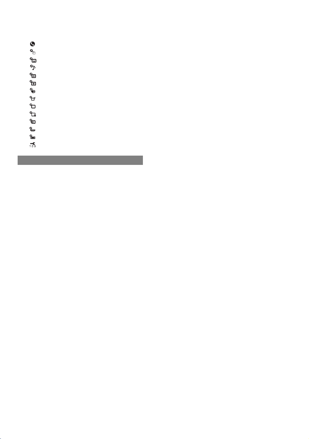
TV Setting Description......................................37
Product Support .....................................37
Clock/Timers Settings ............................37
Picture Settings ...................................... 37
Sound Settings.......................................39
Screen Settings ......................................40
Video Options Settings...........................42
Audio Options Settings...........................43
Channel Settings....................................44
CC
Closed Captions (CC) Settings .............. 45
Parental Lock Settings ...........................45
External Inputs Settings .........................47
HDMI Settings ........................................48
General Settings..................................... 48
Initial Setup............................................. 48
Other Information
Replacing the Lamp..........................................49
How to Replace the Lamp............................49
Troubleshooting................................................ 52
Specifications.................................................... 56
Index................................................................... 57
4

Important Safety Instructions
1) Read these instructions.
2) Keep these instructions.
3) Heed all warnings.
4) Follow all instructions.
5) Do not use this apparatus near water.
6) Clean only with dry cloth.
12) Use only with the cart, stand, tripod,
bracket, or table specified by the
manufacturer, or sold with the
apparatus. When a cart is used, use
caution when moving the cart/
apparatus combination to avoid injury
from tip-over.
13) Unplug this apparatus during
lightning storms or when unused
for long periods of time.
14) Refer all servicing to qualified
service personnel. Servicing is
required when the apparatus has
been damaged in any way, such as
power-supply cord or plug is
damaged, liquid has been spilled or
objects have fallen into the
apparatus, the apparatus has been
exposed to rain or moisture, does
not operate normally, or has been
dropped.
7) Do not block any ventilation
openings. Install in accordance with
the manufacturer’s instructions.
8) Do not install near any heat sources
such as radiators, heat registers,
stoves, or other apparatus (including
amplifiers) that produce heat.
9) Do not defeat the safety purpose of
the polarized or grounding-type
plug. A polarized plug has two
blades with one wider than the other.
A grounding type plug has two
blades and a third grounding prong.
The wide blade or the third prong are
provided for your safety. If the
provided plug does not fit into your
outlet, consult an electrician for
replacement of the obsolete outlet.
10) Protect the power cord from being
walked on or pinched particularly at
plugs, convenience receptacles, and
the point where they exit from the
apparatus.
11) Only use attachments/accessories
specified by the manufacturer.
s Be sure to observe the TV’s “For Safety” section on page 7.
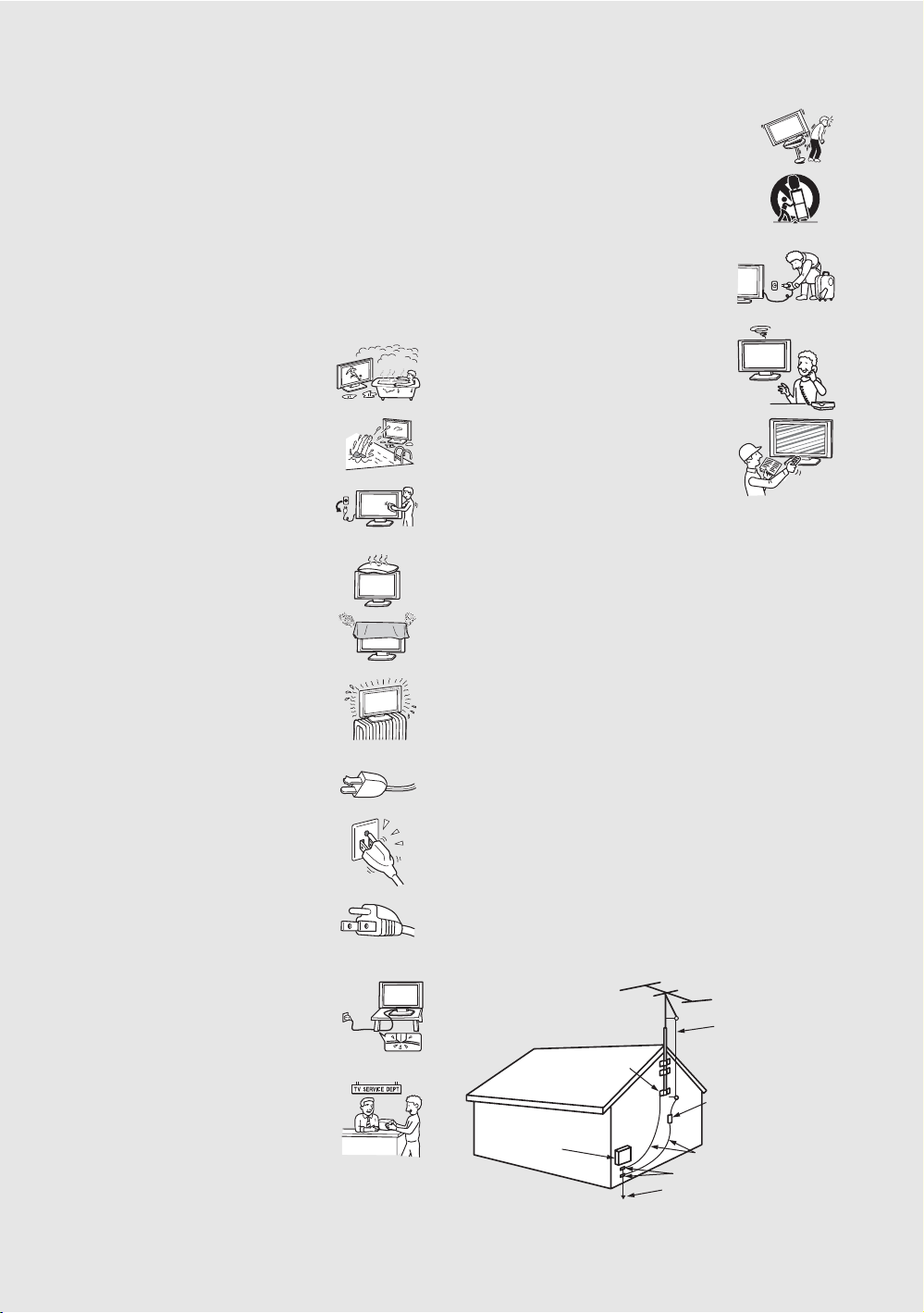
Antennas
Outdoor Antenna Grounding
If an outdoor antenna is installed, follow the precautions below. An
outdoor antenna system should not be located in the vicinity of overhead
power lines or other electric light or power circuits, or where it can come
in contact with such power lines or circuits.
WHEN INSTALLING AN OUTDOOR ANTENNA SYSTEM,
EXTREME CARE SHOULD BE TAKEN TO KEEP FROM
CONTACTING SUCH POWER LINES OR CIRCUITS AS CONTACT
WITH THEM IS ALMOST INVARIABLY FATAL.
Be sure the antenna system is grounded so as to provide some protection
against voltage surges and built-up static charges.
Section 810 of the National Electrical Code (NEC) in USA and Section
54 of the Canadian Electrical Code in Canada provides information with
respect to proper grounding of the mast and supporting structure,
grounding of the lead-in wire to an antenna discharge unit, size of
grounding conductors, location of antenna discharge unit, connection to
grounding electrodes, and requirements for the grounding electrode.
Antenna Grounding According to the NEC
Refer to section 54-300 of Canadian Electrical Code for Antenna
Grounding.
Antenna lead-in
wire
Ground clamp
Electrical
service
equipment
NEC: National
Electrical Code
Antenna discharge
unit (NEC Section
810-20)
Grounding
conductors (NEC
section 810-21)
Ground clamps
Power service grounding
electrode system (NEC
Art 250 Part H)
6
6
Electric shock
Do not touch the AC power cord or the TV with a wet
hand. If you plug/unplug the AC power cord from th e TV
with a wet hand, it may cause electric shock.
Cleaning
s Clean the rear cover area of the TV regularly. Dust in the rear cover
area may cause a problem with the cooling system of the TV set.
s Clean the cabinet of the TV with a dry soft cloth.
To remove dust from the screen, wipe it gently
with a soft cloth. Stubborn stains may be
removed with a cloth slightly dampened with
solution of mild soap and warm water. Never use
strong solvents such as thinner or benzine for cleaning. If the picture
becomes dark after using the TV for a long period of time, it may be
necessary to clean the inside of the TV. Consult qualified service
personnel.
s Unplug the AC power cord when cleaning this unit.
Cleaning this unit with a plugged AC power cord
may result in electric shock.
On Contamination on the Screen Surface
The screen surface has a special coating to reduce reflections. To prevent
screen damage, clean the screen as follows:
s Clean the screen with a soft cloth.
s To remove hard contamination, use a cloth moistened with a solution
of mild detergent and water. Do not spray cleaning solution directly
onto the TV. It should only be sprayed to moisten the cleaning cloth.
s Do not use any type of abrasive pad, alkaline cleaner, acid cleaner,
scouring powder, chemical cloth, or solvent such as alcohol, benzene
or thinner, as these may scratch the screen’s coating.
Service
Damage Requiring Service
Do not attempt to service the set by yourself since
opening the cabinet may expose you to dangerous
voltage or other hazards.
Unplug the set from the wall outlet and refer servicing to
qualified service personnel.
Replacement Parts
When replacement parts are required, be sure the service technician
certifies in writing that he has used replacement parts specified by the
manufacturer that have the same characteristics as the original parts.
Unauthorized substitutions may result in fire, electric shock or other
hazards.
See “Replacing the Lamp” on page 49.
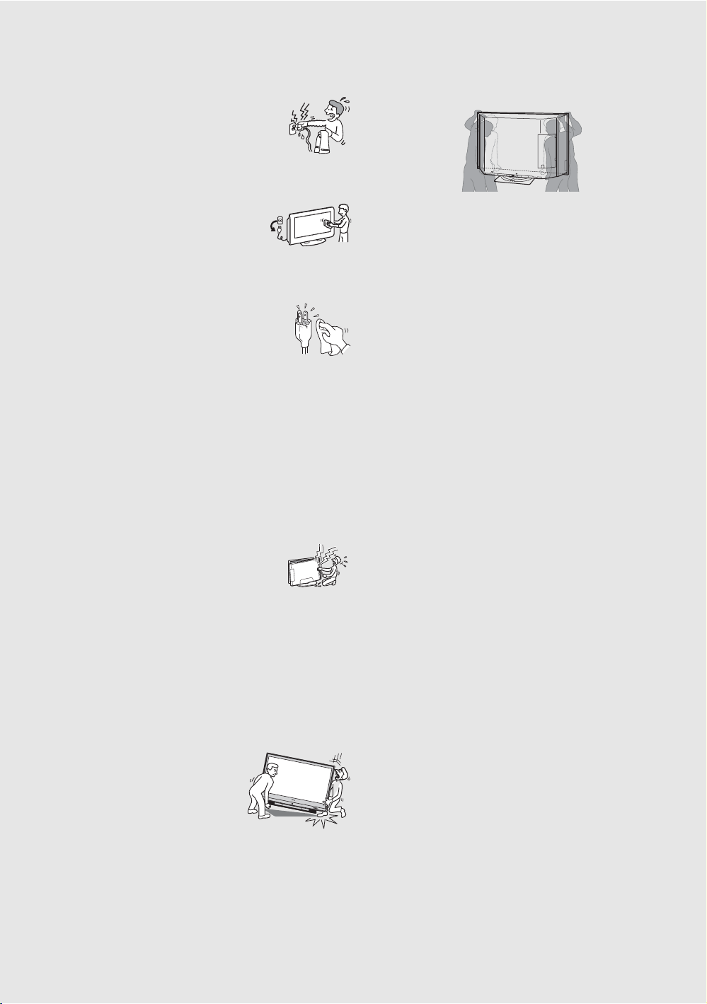
For Safety
Be Careful When Moving the
TV
When you place the TV in position, be careful
not to drop it on your foot or fingers.
Watch your footing while installing the TV.
Carry the TV in the Specified
Manner
If you carry the TV in a manner other than the specified manner and
without the specified number of persons, it may drop and a serious injury
may be caused. Be sure to follow the instructions mentioned below.
s Carry the TV with the specified number of persons (see page 10).
s Hold the TV tightly when carrying it.
S
T
D
/
D
U
O
P
O
W
E
R
s Before carrying the TV, disconnect any accessories or cables.
For Safe Operations
Always switch off by pressing POWER button on the remote or the TV
first to ensure proper lamp cooling process.
Caution
Do not use the TV at altitudes higher than 3,000 m, as doing so might
cause malfunction.
About the TV
Although the TV is made with high-precision technology, black dots may
appear or bright points of light (red, blue, or green) may appear constantly
on the screen. This is a structural property of the panel and is not a defect.
Installation
s If direct sunlight or other strong illumination shines on the screen,
part of the screen may appear white due to reflections from behind the
screen. This is a structural property of the TV.
Do not expose the screen to direct illumination or direct sunlight.
s The picture quality may be affec ted by your viewing position. For the
best picture quality, install your TV according to “Recommended
Viewing Area” on page 12.
s When installing your TV against a wall, keep it at least 4 inches (10
cm) away from the wall.
Projection Lamp
s Your TV uses a projection lamp as its light source. It is time to replace
the lamp with a new one (not supplied) when:
• the message, “Projection lamp is nearing end of life. Please
replace the lamp.” appears on the screen,
• the lamp replacement indicator on the front panel blinks in red,
• screen images become dark,
• no image appears on the display after prolonged use.
s In rare instances, the bulb may pop inside the lamp unit, but the lamp
unit is designed to contain all of broken glass pieces inside the lamp
unit. (See “Replacing the Lamp” on page 49.)
s When the lamp eventually burns out, you may hear a noticeable pop
sound. This is normal and is inherent in this type of lamp.
Cooling Fans
This TV uses cooling fans. You may hear the noise of fans running,
depending on the placement of your TV. The noise may be more
noticeable during the night or when the background noise level is low.
Disposal of Used Batteries
To preserve our environment, dispose of used batteries according to your
local laws or regulations.
For Customers in the United States
Lamp in this product contains mercury. Disposal of
these materials may be regulated due to
environmental considerations. For disposal or
recycling information, please contact your local
authorities or the Electronic Industries Alliance
(http://www.eiae.org).
7
7
Welcome to the World of BRAVIA™
o
Thank you for purchasing this Sony BRAVIA™ high-definition television. The quality of the image
you see on your BRAVIA TV is only as good as the quality of the signal it receives. To experience
the full detail of your new BRAVIA TV, you need access to HD programming. Your BRAVIA TV can
receive and display HD programming from:
• Over-the-air broadcasting via HD-quality antenna
• HD cable subscription
• HD satellite subscription
• Blu-ray Disc™ Player or other external equipment
Contact your cable or satellite provider for information on upgrading to HD programming.
To learn more about HDTV, visit: http://www.sony.com/HDTV
The Four Steps to Full HD Experience: Set, Sound, Source, and Setup
Along with your BRAVIA TV set, a complete HD system requires an HD sound system, a
source of HD programming and proper setup connections. This manual explains basic setup
connections (see page 17). The Quick Setup Guide, enclosed separately, illustrates how to
connect other optional equipment.
Picture Quality and Aspect Ratio
You can enjoy crisp, clear images, smooth movement and high-impact visuals from 1080 HD
signals. When you compare a high-definition signal to a standard analog signal, you will notice
a big difference. The 1080 HD signals provide more than twice the vertical resolution of the
standard TV signal.
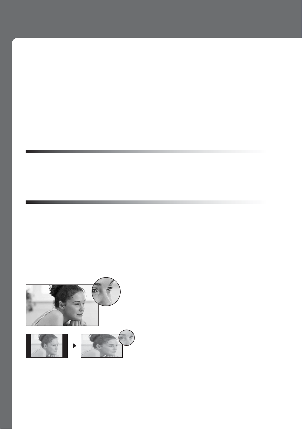
High-definition and standard-definition signals are transmitted with different aspect ratios (the
width-to-height ratio of the image). HDTV uses a wider screen than conventional standarddefinition TV.
16:9 (high-definition) source
Most HDTV signals use a wide screen aspect rati
of 16:9. The 16:9 fills your BRAVIA screen and
maintains a crisp, clear, vivid picture.
4:3 (standard-definition) source
Most standard-definition signals use a boxy 4:3
aspect ratio. When a 4:3 image is displayed on an
HDTV, you will see black bars on the sides. The
picture quality may not be as sharp as with HD
sources.
~
• You can use the Wide Mode function of the TV to adjust the 4:3 image to fit the entire screen (see pages 26, 40
and 42).
8
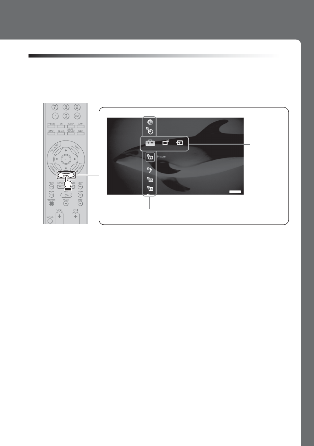
TV Home Menu: XMB™ (XrossMediaBar)
The XMB™ is a menu of BRAVIA features and input sources displayed on the TV screen. The
XMB
HOME button on your remote control to access the XMB
is an easy way to select programming and adjust settings on your BRAVIA TV. Press the
™
Product Support
Clock/Timers
.
™
Settings
Media
Category
Bar
Sound
Screen
Video Options
TV
Category Object Bar
From the horizontal Media Category Bar you can control:
• Settings: timer, picture, sound, screen and other options (see page 37 for customization
options).
• TV Channels: available channels are displayed on the vertical Category Object Bar.
• External Inputs: cable, satellite, VCR, DVD players or other inputs can also be selected
from the Category Object Bar for the External Inputs.
9
Getting Started
1. Installing the TV
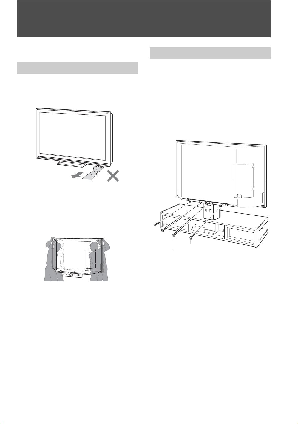
Carrying Your TV
Carrying the TV requires four people.
Do not carry the TV by grasping only the front
panel. Avoid holding the bottom middle part of the
screen. Doing so may damage the panel.
When moving the TV, hold it as shown in the
illustration below.
When lifting the rear and side, place the hands in
the holes on the lower portion of the cabinet.
Two persons should lift and support from the front,
while the other two lift the sides.
Preventing the TV from Toppling Over
As a protective measure, secure the TV as follows.
Using the TV stand SU-RS52U
Sony strongly recommends using the TV stand
SU-RS52U.
To secure the TV, use the two shafts and two
screws that were securing the Table-Top Stand.
Fasten the two shafts first, and then fasten the two
screws.
If you have connected cables and cords, be sure to
unplug them before moving the TV.
To ensure the safety of children and the TV, keep
children away from the TV during installation.
Climbing on or pushing the TV or its stand may
cause it to fall and may damage the TV.
10
Screw
Shaft
~
• For more information, refer to the instruction guide
provided by the TV stand SU-RS52U.
When using other TV stands
3
Table-Top
Stand
TV
stand
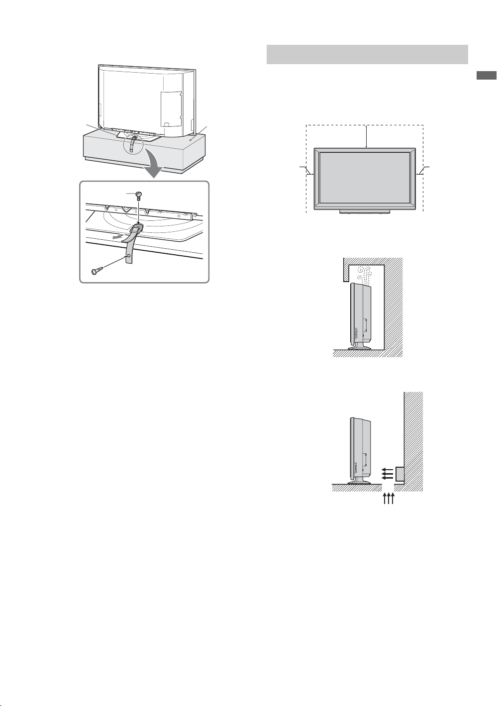
When Installing Your TV against a Wall
Keep your TV at least 4 inches (10 cm) away from
the wall to provide proper ventilation. Blocking
the ventilation opening of the cooling fan may
damage the TV.
12 inches
(approx. 30 cm)
Getting Started
2
3
1
1 Screw the support belt (supplied) to the TV
stand with a wood screw (supplied).
2 Attach the support belt to the Table-Top Stand
with the securing screw (supplied) using a
coin, etc.
3 Adjust the length by pulling the support belt
toward you while holding the Table-Top
Stand.
~
• Be sure to take measures to prevent the TV from
toppling over and causing injury.
• The supplied wood screw may not be used depending
on the type of TV stand. In this case, or when the
securing strength is not enough, use commercial
1
/8 to 3/16 inch (3 to 4 mm) diameter to fit to the
screws
TV stand. Consult your dealer about the types of
screw(s).
4 inches
(10 cm)
Never install the TV as follows:
Air circulation is blocked.
Air blown into cooling fan.
4 inches
(10 cm)
~
• Do not install the TV near any ventilation, as it may
affect the normal TV operating temperature.
• Be sure that the ventilation opening on the side of the
TV is not blocked by curtains or other materials.
• Dirt may accumulate near the ventilation when the TV
is placed against the wall depending on its material.
11
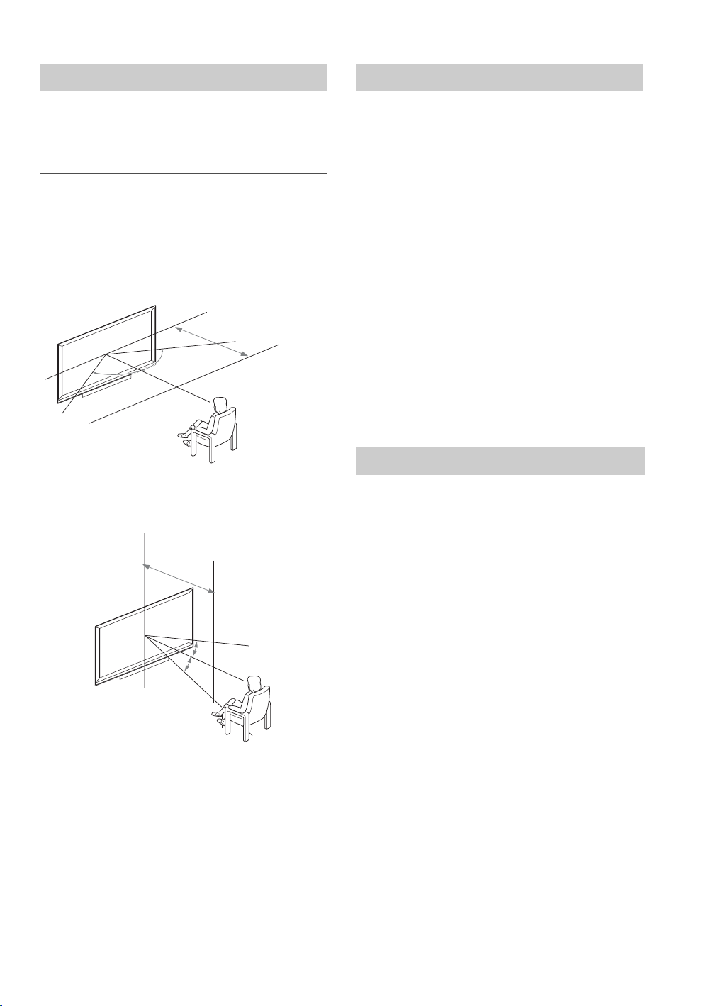
Recommended Viewing Area
65.
65˚
min
.
6.6 ft.
(app
rox.
2.0 m)
50"
55 in
c
hes min
.
6.8 ft
.
(app
rox.
2.1 m)
60 in
c
hes min
.
7.0 ft
.
(app
rox.
2.2 m)
Screen
Your viewing position may affect the picture
quality.
For the best picture quality, install your TV within
the areas shown below.
Model Viewing distance
KDS-Z60XBR5
KDS-Z70XBR5
Horizontal Viewing Area
60 in
70 inches min. 8.0 ft. (approx. 2.4
55 in
60 inches min. 7.0 ft. (approx. 2.2 m)
min. 7.0 ft. (approx. 2.2 m)
min. 8.0 ft. (approx. 2.4 - 2.5 m)
70 inches min. 8.0 ft. (approx. 2.4
60 inches min. 7.0 ft. (approx. 2.2 m)
min
6.6 ft
(app
50"
65
65˚
65˚
65
Vertical Viewing Area
hes min
7.0 ft
hes min
6.8 ft
(app
(app
30
30˚
˚
2.2 m)
-
2.1 m)
2.0 m)
2.5 m)
-
2.5 m)
To minimize reflection, the screen surface has a
special coating.
Inappropriate cleaning methods could damage the
screen surface. Special care is required.
Cleaning the Screen Surface
Dust and dirt on the screen can affect the picture
quality. To dust off the screen use a soft cloth. Be
sure to follow the cleaning instruction on page 7
for stubborn stains and dirt.
Temporary Image Retention
When high contrast non-moving images such as
station logos and channel numbers are displayed
for a long period of time, there may be some image
retention on the screen. This is only a temporary
condition. Turning off the power for a while or
letting the TV run on another channel will
eliminate the image retention.
Projection Lamp
Your TV uses a projection lamp as its light source.
As with any lamp, it has a lifespan and needs to be
replaced when the Lamp Indicator flashes or the
screen becomes darker. Your TV also has a
function to display a message, “Projection lamp is
nearing end of life. Please replace the lamp.” to let
you know that the lamp has reached its expected
lifespan. Note the following:
s After turning on your TV, it may take a while
(one minute or less) before the picture
appears.
s When the projection lamp wears out, the
screen goes dark. Replace the lamp with a
new Sony XL-5200 replacement lamp (not
supplied).
s After lamp is replaced, please set the Lamp
Replacement option in the General
settings (see page 48).
“How to Replace the Lamp”, see page 49.
~
• The light emitted from the lamp is quite bright when
your TV is in use. To avoid eye discomfort or injury,
do not look into the light housing when the power is
on.
12
2. Locating Inputs and Outputs
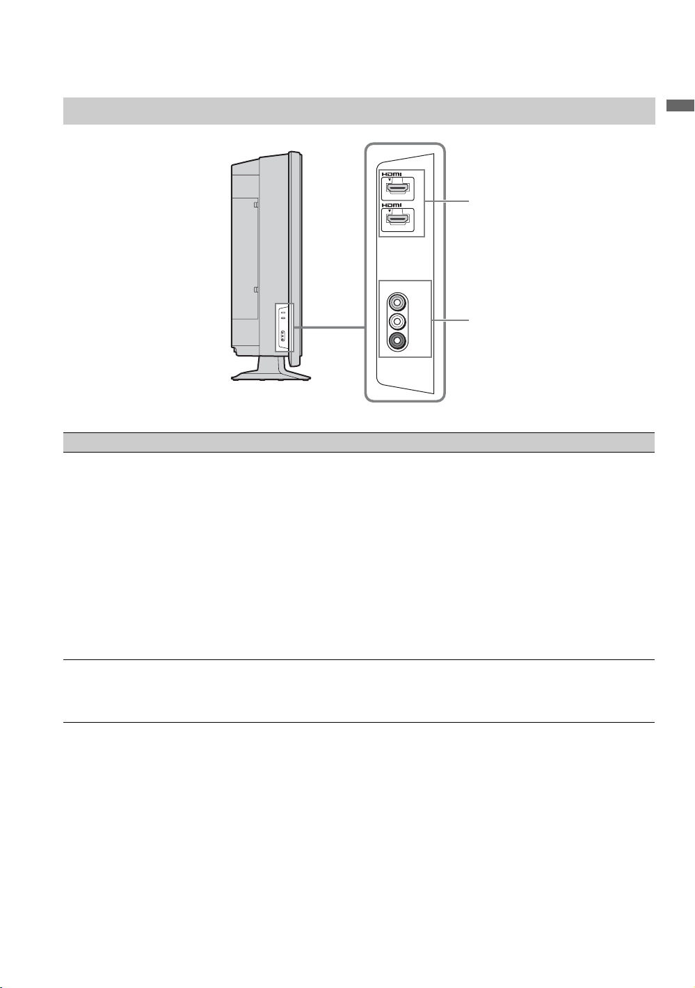
Left Side
Item Description
1 HDMI IN 2/3
HDMI
HDMI (High-Definition Multimedia Interface) provides an uncompressed, all-digital
audio/video interface between this TV and any HDMI-equipped audio/video equipment,
such as a set-top box, DVD player, Blu-ray Disc Player, A/V receiver as well as PC.
HDMI supports enhanced, or high-definition video, plus digital audio.
~
• HDMI connection is necessary to view 480i, 480p, 720p, 1080i, 1080p and 1080/24p
formats. Note that this TV displays all video input signals in a resolution of 1,920 dots
× 1,080 lines.
• Be sure to use only an HDMI cable that bears the HDMI logo.
• When HDMI control compatible equipment is connected, communication with the
connected equipment is supported. Refer to page 48 to set up this communication.
• When connecting a HDMI control compatible audio system with HDMI jack, be sure to
also connect to the OPTICAL OUT jack.
2 VIDEO 2 IN
VIDEO/
L(MONO)AUDIO-R
Connects to the composite video and audio output jacks on your A/V equipment such as
a VCR or other video equipment.
VIDEO 2 IN
2 IN
3 IN
VIDEO
L (MONO)
AUDIO
R
Getting Started
1
2
13
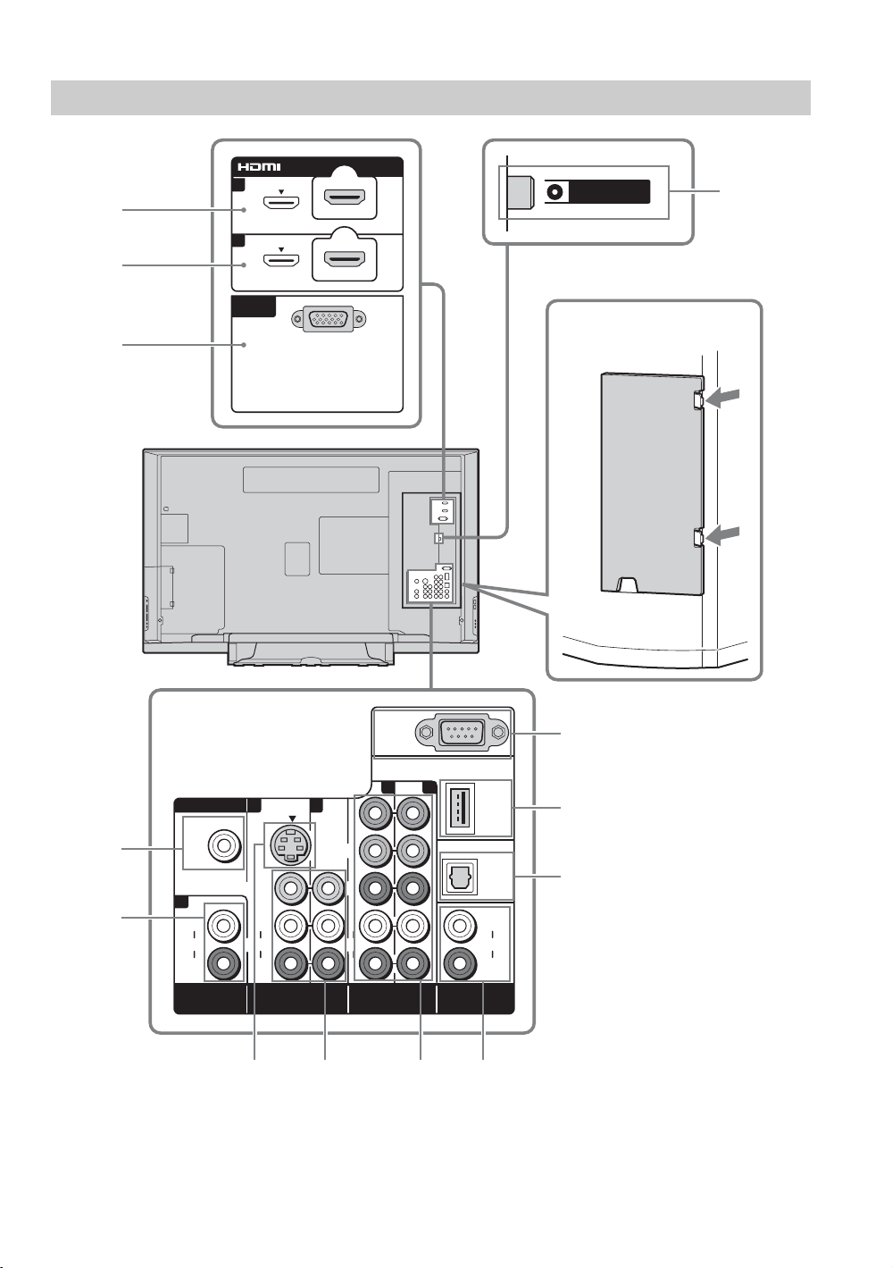
Left Side Rear
5 6 7 8
1
2
IN
1
4
VHF/UHF/CABLE
4
3
3
1
PC IN
AUDI O
1
L
AUDI O
R
HDMI IN
PC IN
RGB
1
S VIDEO
VIDEO
(MONO)
AUDI O
L
R
VIDEO IN
3
P
P
AUDI O
REMOTE
12
Y
B
R
L
R
COMPONENT IN
(1080p/1080i/
720p/480p/480i)
DMeX/
SERVICE
DIGITAL
AUDI O
OUT
(OPTICAL)
L
AUDI O
R
AUDIO OUT
(VAR/FIX)
(VAR/FIX)
Press the two clamps to open
the cover.
qa
0
9
14
Item Description
1 HDMI IN 1
HDMI/
R-AUDIO-L
2 HDMI IN 4
HDMI
HDMI (High-Definition Multimedia Interface) provides an uncompressed, all-digital
audio/video interface between this TV and any HDMI-equipped audio/video equipment,
such as a set-top box, DVD player, Blu-ray Disc Player, A/V receiver as well as PC.
HDMI supports enhanced, or high-definition video, plus digital audio.
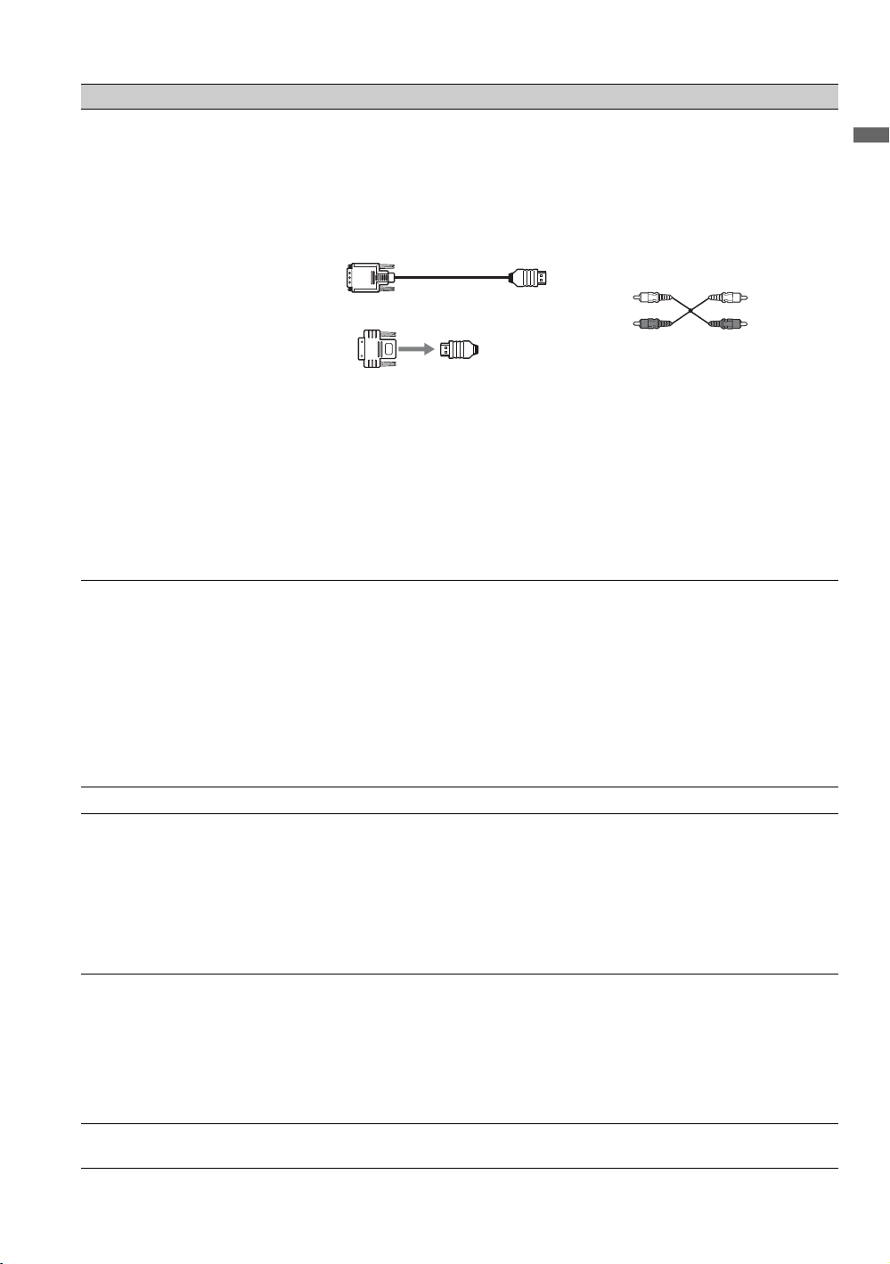
If the equipment has a DVI jack and not an HDMI jack, connect the DVI jack to the
HDMI IN 1 (with DVI-to-HDMI cable or adapter) jack, and connect the audio jack to the
AUDIO IN (L/R) jacks of HDMI IN 1.
DVI-to-HDMI cable
DVI-to-HDMI adapter
~
• HDMI connection is necessary to view 480i, 480p, 720p, 1080i, 1080p and 1080/24p
formats. Note that this TV displays all video input signals in a resolution of 1,920 dots ×
1,080 lines.
• Be sure to use only an HDMI cable that bears the HDMI logo.
• When HDMI control compatible equipment is connected, communication with the
connected equipment is supported. Refer to page 48 to set up this communication.
• When connecting an HDMI control compatible audio system with HDMI jack, be sure
to also connect to the OPTICAL OUT jack.
3 PC IN
(RGB/AUDIO)
Connects to a personal computer’s video output connector using an HD15-HD15 cable
with ferrite core (analog RGB, not supplied). Can also be connected to other analog RGB
equipment.
See “PC Input Signal Reference Chart” on page 19 for the signals that can be displayed.
~
• For some Apple Macintosh computers, it may be necessary to use an adapter (not
supplied). If this is the case, connect the adapter to the computer before connecting the
HD15-HD15 cable with ferrite core.
• If the picture is noisy, flickering or not clear, adjust Phase and Pitch of Screen
settings on page 41.
4 VHF/UHF/CABLE RF input that connects to your Cable or VHF/UHF antenna.
5 VIDEO IN 1
S VIDEO
6 VIDEO IN 1/3
VIDEO/
L(MONO)AUDIO-R
7 COMPONENT IN
1/2 (1080p/1080i/
720p/480p/480i)/
L-AUDIO-R
8 AUDIO OUT
(VAR/FIX)
Connects to the S VIDEO output jack of your VCR or other video equipment that has
S VIDEO. The S VIDEO provides better picture quality than composite video (6)
connection.
If both composite video and S VIDEO are connected, S VIDEO signal has priority.
Connects to the composite video and audio output jacks on your A/V equipment such as
a VCR or other video equipment.
Connects to your equipment’s component video (YP
jacks. Component video provides better picture quality than the S VIDEO (5) or the
composite video (6) connection.
BPR) output jack and audio (L/R)
~
• Component video (YPBPR) connection is necessary to view 480i, 480p, 720p, 1080i and
1080p formats. Note that this TV displays all video input signals in a resolution of
1,920 dots × 1,080 lines.
Connects to the left and right audio input jacks of your analog audio equipment. You can
use these outputs to listen to your TV’s audio through your stereo system.
Getting Started
Audio cable
(Continued)
15

Item Description
9 DIGITAL AUDIO
OUT (OPTICAL)
x
0 DMe
qa REMOTE This jack is for receiving the external control signal.
/ SERVICE This USB port is for service only unless you are connecting the optional BRAVIA
Connects to the optical audio input of your digital audio equipment that is PCM/Dolby
Digital compatible. Dolby Digital Audio signal from the HDMI input will be output as
PCM. Dolby Digital Audio signal from digital channels will be output as it is.
x
external module (DMe
).
16
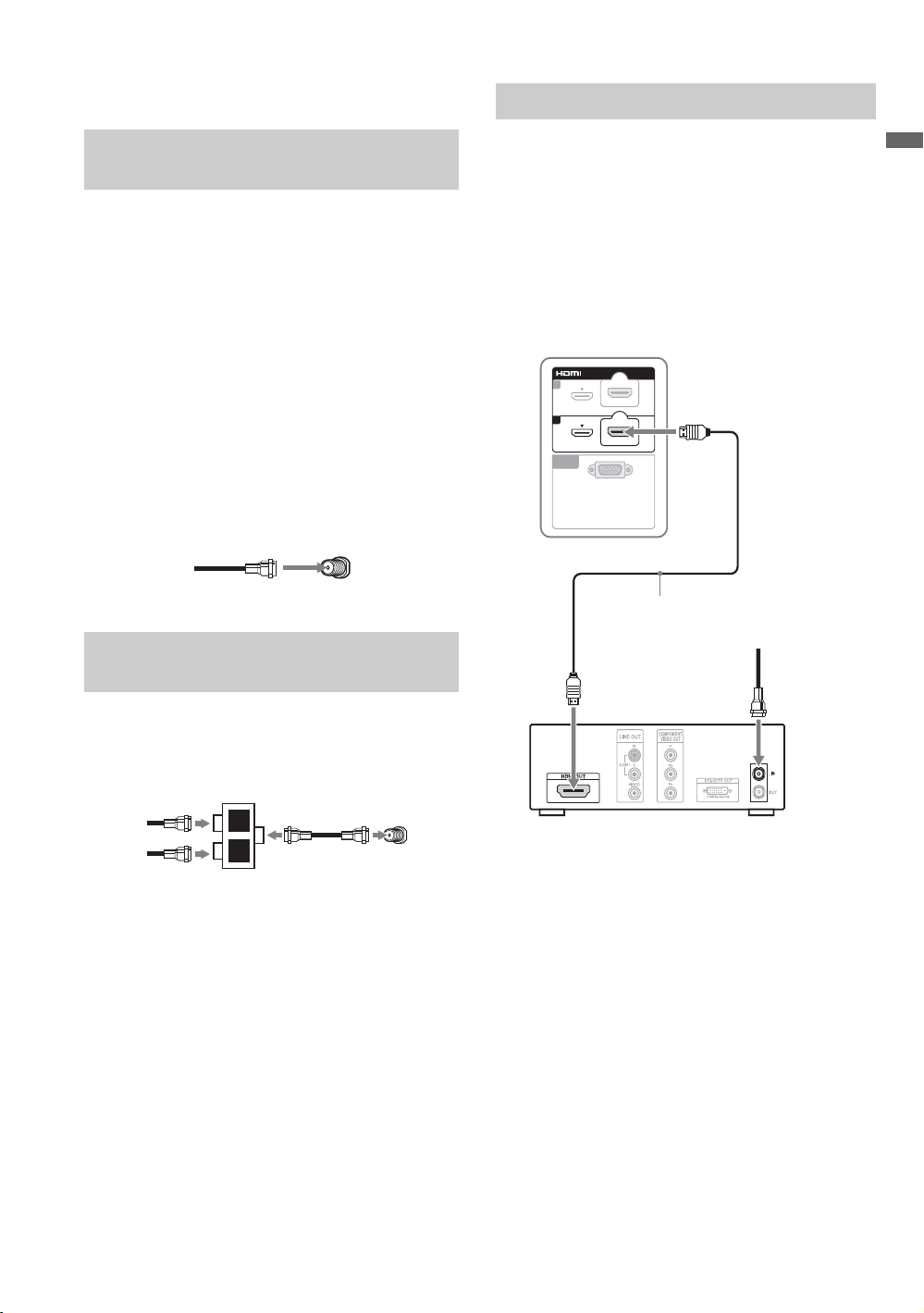
3. Connecting the TV
HD Cable Box/HD Satellite Box
Cable System or VHF/UHF Antenna System
You can enjoy high-definition and standarddefinition digital programming (if available in
your area) along with standard-definition analog
programming.
~
• This TV is capable of receiving unscrambled digital
programming for both cable (QAM and 8VSB) and
external VHF/UHF antenna (ATSC).
• It is strongly recommended that you connect the
antenna/cable input using a 75-ohm coaxial cable to
receive optimum picture quality. A 300-ohm twin lead
cable can be easily affected by radio frequency
interference, resulting in signal degradation.
Cable or VHF/UHF (or VHF only)
75-ohm coaxial
cable
VHF/UHF/CABLE input
Cable System and VHF/UHF Antenna System
Use an optional A-B RF switch (not supplied) to
switch between the cable and over-the-air antenna
programming, as indicated below.
Side rear of TV
You can also enjoy high-definition programming
by subscribing to a high-definition cable service or
a high-definition satellite service. For the best
possible picture, make sure you connect this
equipment to your TV via the HDMI or
component video (with audio) input on the back of
your TV.
Shown with HDMI Connection
Side rear of TV
IN
1
4
PC IN
RGB
HDMI cable
HD cable box/
HD satellite box
CATV/Satellite
antenna cable
Getting Started
A-B RF switch
Cable
Antenna
A
B
VHF/UHF/CABLE input
Side rear of TV
~
• Be sure to set the Cable setting to On or Off in the
Channel settings for the type of input signal you
choose (see page 44).
(Continued)
17
Shown with DVI Connection
VIDEO
AUDIO
L
(MONO)
R
AUDIO
L
R
AUDIO
L
R
P
R
P
B
AUDIO
L
R
1
VIDEO IN
HDMI IN
AUDIO OUT
COMPONENT IN
(1080p/1080i/
720p/480p/480i)
(VAR/FIX)
DIGITAL
AUDIO
OUT
(OPTICAL)
Side rear of TV
IN
1
CATV/Satellite
antenna cable
4
PC IN
RGB
DVI-to-HDMI cable
HD cable box/
HD satellite box
AUDIO-L
(white)
AUDIO-R
(red)
Audio cable
~
• If the equipment has a DVI jack and not an HDMI jack, connect the DVI jack to the HDMI IN 1 (with DVI-to-HDMI
cable or adapter) jack and connect the audio jack to the AUDIO IN (L/R) jacks of HDMI IN 1. For details, see
page 15.
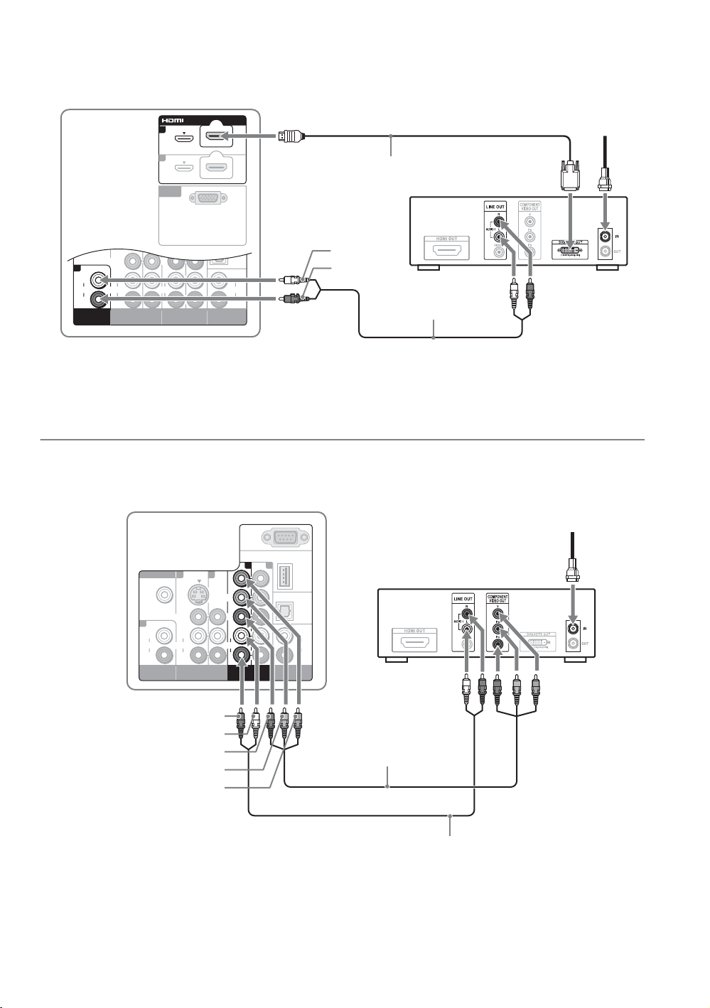
Shown with Component Connection
Side rear of TV
PC IN
113
S VIDEO
AUDIO
VIDEO
L
(MONO)
L
AUDIO
AUDIO
R
R
HDMI IN
VIDEO IN
REMOTE
1 2
Y
P
B
P
R
L
AUDIO
R
COMPONENT IN
(1080p/1080i/
720p/480p/480i)
DMeX/
SERVICE
DIGITAL
AUDIO
OUT
(OPTICAL)
AUDIO
AUDIO OUT
(VAR/FIX)
HD cable box/
HD satellite box
L
R
CATV/Satellite
antenna cable
18
AUDIO-R (red)
AUDIO-L (white)
P
R (red)
P
B (blue)
Y (green)
Component video cable
Audio cable
 Loading...