

Sony KDR60XBR2 Schematic
SERVICE MANUAL
SP-3
CHASSIS
MODEL COMMANDER DEST. CHASSIS NO.
–––––– –––––––––––– ––––– –––––––––––
KDS-R60XBR2
KDS-R60XBR2
KDS-R70XBR2
KDS-R70XBR2
RM-YD009 USA
RM-YD009
RM-YD009
RM-YD009
CANADA
USA
CANADA
MODEL COMMANDER DEST. CHASSIS NO.
–––––– –––––––––––– ––––– –––––––––––
KDS-50A2000/50A2010/55A2000/60A2000/60A2010
POWER
LAMP
TIMER
POWER
POWER
LAMP
TIMER
BD/DVD
RM-YD009KDS-R60XBR2/R70XBR2
SXRD PROJECTION TV

KDS-R60XBR2/R70XBR2
RM-YD009 RM-YD009
Specifications
Te le vision system:
NTSC American TV Standard
ATSC (8V SB terrestrial) ATSC compliant 8VSB
QAM on cable ANSI/SCTE 07 2000
Channel coverage:
Ter rest rial (analog) 2-69
Cable TV (analog) 1-125
Ter rest rial (digital) 2-69
Cable TV (digital) 1-135
Antenna:
75-ohm external terminal for VHF/UHF
Screen size (measured diagonally):
KDS-R60XBR2: 60 inches
KDS-R70XBR2: 70 inches
Projection system
3 SXRD panel, 1 lens projection system
SXRD panel
0.61 inch SXRD panel 6,220,800 pixels (2,073,600 × 3)
Projection lens
High performance, large diameter hybrid lens F2.5
Lamp
Ultra High Pressure Lamp, 180 W, XL-X5300
VIDEO IN 1/2/4:
S VIDEO (4-pin mini DIN) (VIDEO 1 only):
VIDEO: 1 Vp-p, 75 ohms unbalanced, sync negative
AUDIO: 500 mVrms (100% modulation)
HD/DVD IN 5/6:
YPBPR (Component Video):
AUDIO: 500 mVrms (100% modulation)
HDMI IN 3/7/8:
HDMI: Video: 480i, 480p, 720p, 1080i, 1080p
AUDIO (for HDMI IN 8 only):
Y: 1.0 Vp-p, 75 ohms unbalanced, sync negative
C: 0.286 Vp-p (Burst signal), 75 ohms
Impedance: 47 kilohms
Y: 1.0 Vp-p, 75 ohms unbalanced,
sync negative
B
: 0.7 Vp-p, 75 ohms
P
R
: 0.7 Vp-p, 75 ohms
P
Signal format: 480i, 480p, 720p, 1080i
Impedance: 47 kilohms
Audio: Two channel linear PCM 32, 44.1 and
48 kHz, 16, 20 and 24 bits
500 mVrms (100% modulation)
Impedance: 47 kilohms
AUDIO OUT:
500 mVrms (100% modulation) (Fixed)
More than 1 Vrms at the maximum volume setting (Variable)
DIGITAL OUT (OPTICAL):
Optical Digital Audio Output (PCM/Dolby digital)
PC IN 9:
D-sub 15-pin, analog RGB, 0.7 Vp-p, 75 ohms, positive
See the PC Input Signal Reference Chart on page 77
PC AUDIO INPUT:
Stereo mini jack, 0.5 Vrms, 47 kilohms
Speaker:
Size:
8cm (
3 1/8 inches)
(2)
Speaker output:
15 W + 15 W
Power requirement:
120 V AC, 60 Hz
Power consumption:
In use: 285 W
In standby: Less than 0.2 W
Dimensions (W/H/D):
KDS-R60XBR2: 1674 × 1016 × 514 mm
×
(66
KDS-R70XBR2: (with speakers) 1885
1
(74
(without speakers) 1714
1
(67
40 × 20
/
4
×
45 1/
/
2
×
45 1/
1
/4 inches)
×
2
×
24 1/8 inches)
2
×
24 1/8 inches)
1154 × 611 mm
×
1154 × 611 mm
Mass:
KDS-R60XBR2: 55 kg (121 lb.)
KDS-R70XBR2: 73 kg (161 lb.)
Supplied accessories:
Remote control RM-YD009 (1)
Size AA batteries (2)
Side cover (2) (KDS-R70XBR2 only)
Operating Instructions (1)
Quick Setup Guide (1)
War rant y Card (1)
Product Registration Card (1)
Replacement Lamp XL-5300 (1)
Optional accessories:
TV Stand: SU-RS51U
Lamp: XL-5300
Design and specifications are subject to change
without notice.
– 2 –

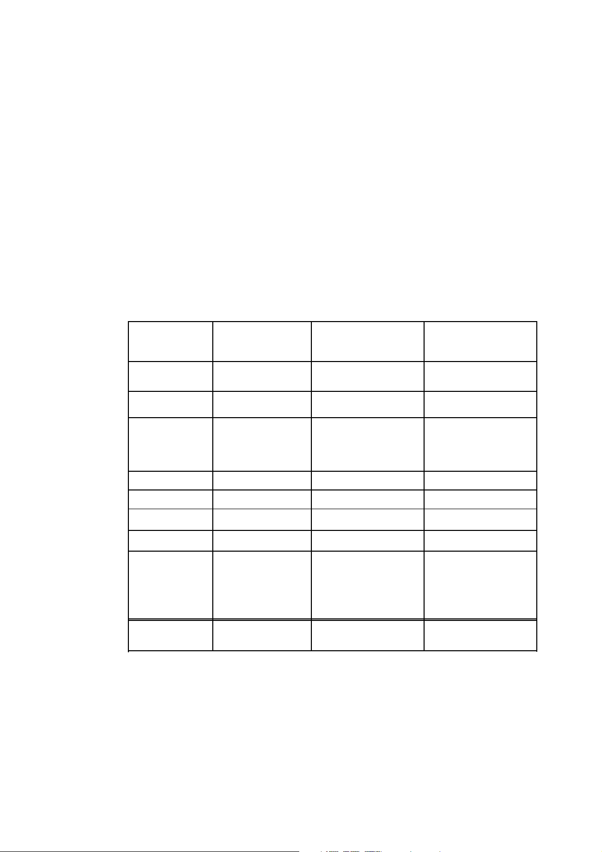
PC Input Signal Reference Chart
Resolution
Horizontal frequency
(kHz)
Ve rt i cal
frequency (Hz)
Standard
Signals Horizontal
(Pixel)
× Ve r tical
(Line)
VGA
640 × 480 31.5 60 VGA
640 × 480 37.5 75 VESA
720 × 400 31.5 70 VGA-T
SVGA
800 × 600 37.9 60 VESA Guidelines
800 × 600 46.9 75 VESA
XGA
1024 × 768 48.4 60 VESA Guidelines
1024 × 768 56.5 70 VESA
1024 × 768 60.0 75 VESA
WXGA
1280 × 768 47.4 60 VESA
1280 × 768 47.8 60 VESA
1280 × 768 60.3 75 VESA
1360 × 768 47.7 60 VESA
SXGA
1280 × 1024 64.0 60 VESA
1280 × 1024 80.0 75 VESA
HDTV
1920 × 1080 67.5 60 EIA
KDS-R60XBR2/R70XBR2
RM-YD009 RM-YD009
– 3 –
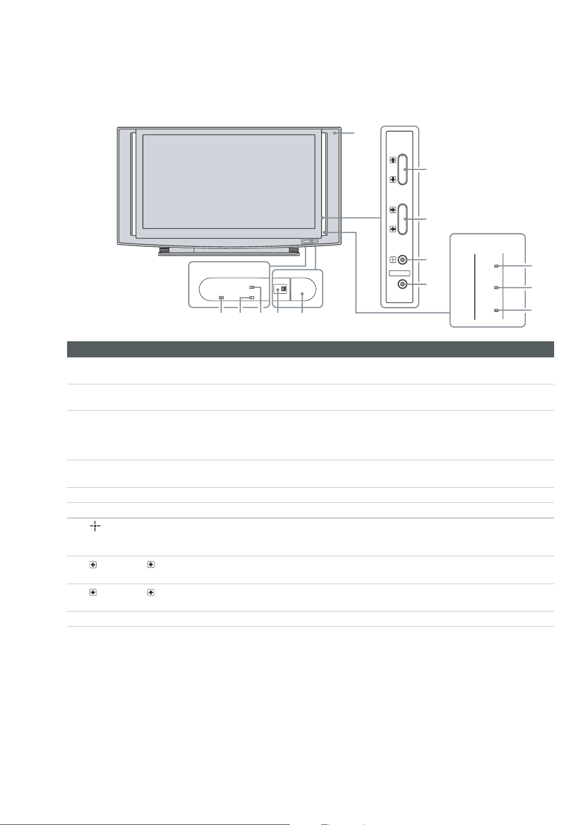
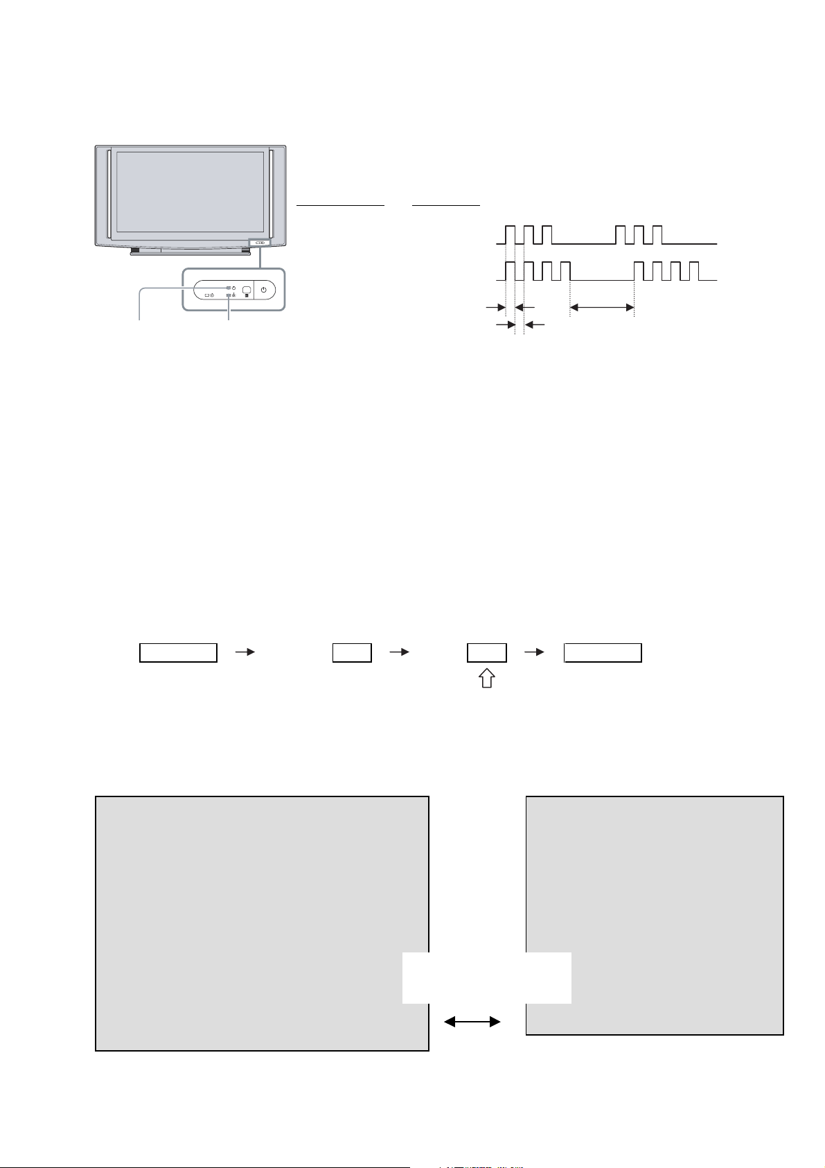
TV Controls
For KDS-R60XBR2
PO WER
TIMER
LAMP
21
354
PO WER
KDS-R60XBR2/R70XBR2
RM-YD009 RM-YD009
0
CHANNEL
3
9
#
VOLUME
3
POWER
LAMP
TIMER
POWER
POWER
LAMP
TIMER
TV/VIDEO
MENU
8
#
For KDS-R70XBR2
7
6
PO WER
LAMP
TIMER
3
2
1
Item Description
TIMER LED When the timer is set, this LED will remain lit even if the TV is turned off. For details, see
1
page 61.
LAMP LED Blinks in red when the lamp for the light source has burned out. For details, see “Replacing the
2
Lamp” on page 66.
POWER LED Lights up in green when the TV is turned on. If the LED blinks in red continuously, this may
3
indicate the display unit needs servicing (see the contacting Sony information on page 2).
When the red LED blinks only three times, the lamp door of the lamp unit or the lamp itself is
not securely attached (see page 68).
(IR) Infrared
4
Receiver
POWER Press to turn on and off the TV.
5
MENU Press to display MENU with TV functions and settings (see “Overview of MENU” on page 47).
6
7
TV/VIDEO
Receives IR signals from the remote control.
Do not put anything near the sensor, as its function may be affected.
Press to cycle through the video inputs. If you set a certain input to Skip in Label Video
Inputs, then the input will not appear. For details, see page 60.
In the MENU screen, this button serves as confirming the selection or setting.
8
Press to adjust the volume. In the MENU screen, these buttons serve as left/right buttons.
VOLUME –/+
9
CHANNEL –/+
Speaker Outputs the audio signal.
q;
Press to scan through channels. To scan quickly through channels, press and hold down either
–/+. In the MENU screen, these buttons serve as up/down buttons.
– 4 –

Replacing the Lamp
The projection lamp, like all lamps, will eventually lose brightness and
functionality, which affects the overall performance of your TV. How long
the lamp maintains its brightness will vary depending upon your usage and
environmental conditions. To maintain the quality of your viewing
experience, Sony recommends that you replace the lamp (1) after
approximately 4,000 hours of use; (2) when the screen becomes dark or the
color looks unusual; (3) when the LAMP LED on the front of the TV blinks;
or (4) when the lamp replacement message appears on the TV screen.
❑
❑
❑
❑
❑
❑
KDS-R60XBR2/R70XBR2
RM-YD009 RM-YD009
WARNING
Electric appliances can cause fire or high temperature, resulting in
injury or death. Be sure to follow the instructions below.
Use the supplied Sony XL-5300 lamp for replacement. Use of any other
lamp may damage the TV.
Do not remove the lamp for any purpose other than replacement. Doing
so may cause injury or fire.
Do not put flammable materials and metal objects inside the lamp
receptacle of the TV after removing the lamp. Doing so may cause fire
or electrical shock. Do not touch the lamp receptacle once the lamp has
been removed.
When the lamp eventually burns out, you may hear a noticeable pop
sound. This is normal and it is inherent to this type of lamp.
In rare instances, the bulb may pop inside the lamp unit, but the lamp
unit is designed to contain all of the broken glass pieces inside the lamp
unit.
This TV’s lamp contains mercury and should be disposed of properly.
Consult your local authorities regarding safe disposal. The material
contained in this lamp are similar to those of a fluorescent lamp, so you
should dispose of it in the same way.
How to Replace the
Lamp
1 Turn off the power on the main unit. Wait several minutes, then unplug
the power cord.
(The cooling fan will continue to operate for about two minutes after
turning the power off.)
2 Wait at least 30 minutes after unplugging the power cord to allow the
lamp to cool down before replacing it. To avoid being burned, do not
touch the lamp receptacle once the lamp has been removed.
– 5 –
3
Take t he new lamp out of the box.
Do not touch the glass portion of the new lamp.
✍
Do not shake the lamp. Vibration can damage the lamp or shorten
its life.
✍
Avoid touching the front glass of a new lamp or the glass of the
lamp receptacle. This may reduce picture quality or lamp life.
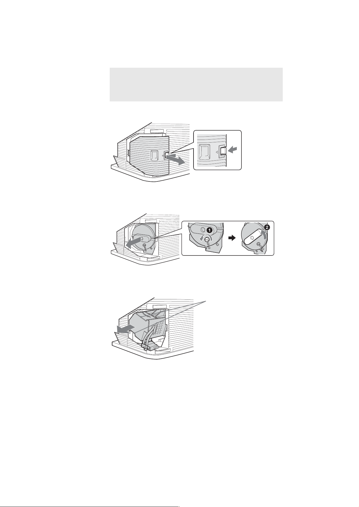
4
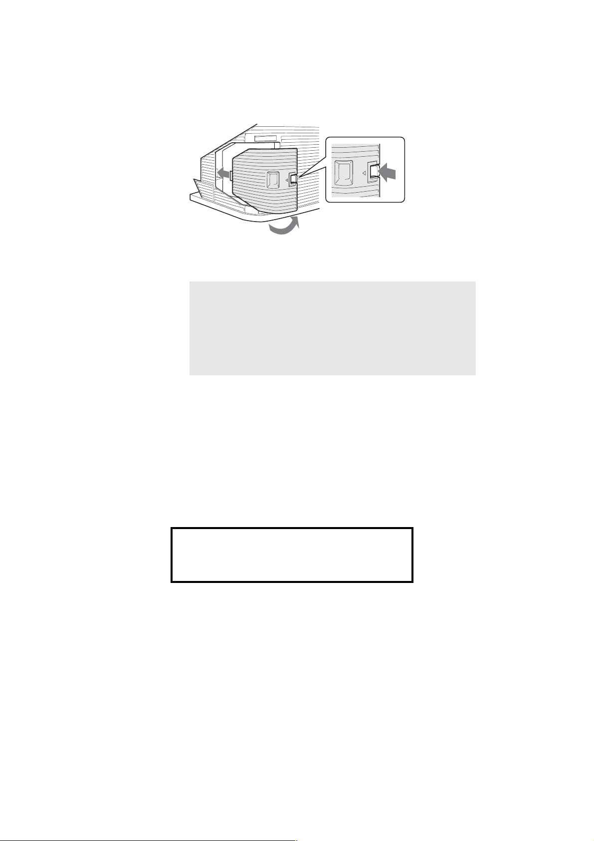
Remove the outside lamp cover.
Release the clamp as shown in the illustration below.
5
Remove the lamp door.
Turn the screw counterclockwise, and then turn the knob to the left until
the marks on the lid and the case line up. Remove the door.
KDS-R60XBR2/R70XBR2
RM-YD009 RM-YD009
6
Pull out the lamp.
Hold the indents on the top and bottom of the lamp, as shown in the
illustration, and pull the lamp straight out.
Hold this part of the lamp
– 6 –
✍ Do not touch the inside of the lamp compartment.
✍ The lamp is very hot immediately after use. Never touch the glass
portion of the lamp or the surrounding parts.
✍ After the used lamp has cooled, place it into the empty box of the
replacement lamp. Never put the used lamp into a plastic bag.
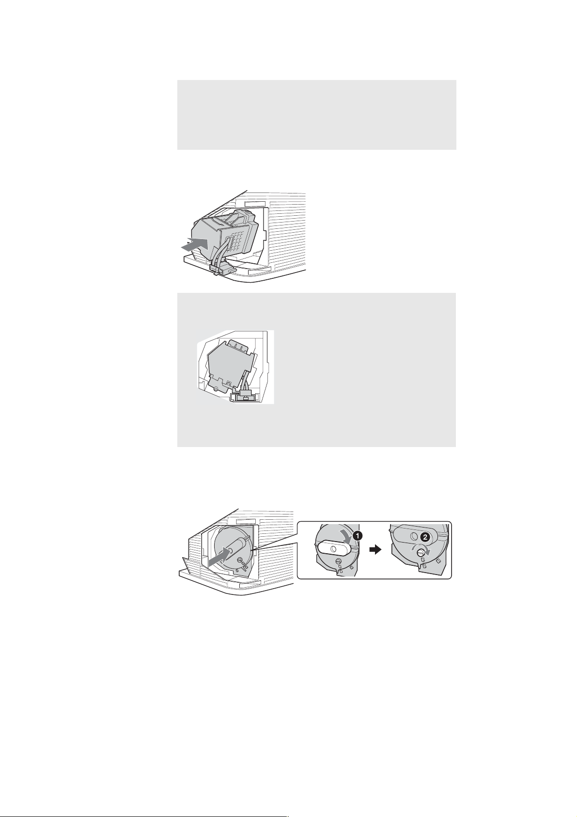
7
Put the new lamp into its place.
Make sure the lamp is securely mounted into the compartment. Failure to
do so may cause a fire or the screen to go dark.
✍ The lamp compartment is tilted, as shown in the following
illustration.
KDS-R60XBR2/R70XBR2
RM-YD009 RM-YD009
✍ If the lamp is not securely reattached, the self-diagnostic function
may be triggered and the POWER LED blinks three times (see
page 37).
8
Reattach the lamp door.
To secure the door, turn the knob to the right while pushing the door in,
until the marks on the lid and the case line up. Then, turn the screw
clockwise to tighten the door.
– 7 –
9
Put the outside lamp cover back in its place.
Replace the cover, inserting it from the left side. Press the clamp on the
right side to secure the cover.
10
Turn on the TV and set the
settings (see page 62). This setting is necessary to inform you when the
next lamp replacement is needed.
Lamp Replacement
option in the
✍ Until you set the Lamp Replacement option, a message
announcing that the lamp is at the end of its life will appear every
time you turn on the TV.
✍ Consult your Sony dealer for a Sony XL-5300 replacement lamp.
✍ Ta ke great care when replacing the lamp or plugging in/unplugging
the connecting cords. Rough handling may cause the TV to fall,
damaging the TV, the TV stand and the floor.
KDS-R60XBR2/R70XBR2
RM-YD009 RM-YD009
Setup
The used lamp
For customers in the United States:
This product contains mercury. Disposal of this product may be regulated if
sold in the United States. For disposal or recycling information, please
contact your local authorities or the Electronics Industries Alliance
(http://www.eiae.org).
❑
Do not leave the used lamp near flammable materials or within the
reach of children.
❑
Do not pour water onto the used lamp or put any object inside the lamp.
Doing so may cause the lamp to burst.
For replacement lamp information visit:
U. S. residents: http://www.sonystyle.com/tv/
Canadian residents: http://www.sonystyle.ca/tv/
– 8 –

SAFETY CHECK-OUT
Fig. B. Checking for earth ground.
Trouble Light
AC Outlet Box
Ohmmeter
Cold-water Pipe
( US model only )
KDS-R60XBR2/R70XBR2
RM-YD009 RM-YD009
After correcting the original service problem, perfom the follow-
ing safety checks before releasing the set to the customer:
l. Check the area of your repair for unsoldered or poorly-sol-
dered connections. Check the entire board surface for solder
splashes and bridges.
2. Check the interboard wiring to ensure that no wires are
“pinched” or contact high-wattage resistors.
3. Check that all control knobs, shields, covers, ground straps,
and mounting hardware have been replaced. Be absolutely
certain that you have replaced all the insulators.
4. Look for unauthorized replacement parts, particularly transistors, that were installed during a previous repair. Point them
out to the customer and recommend their replacement.
5. Look for parts which, through functioning, show obvious
signs of deterioration. Point them out to the customer and
recom mend their replacement.
6. Check the line cords for cracks and abrasion. Recommend
the replacement of any such line cord to the customer.
7. Check the condition of the monopole antenna (if any). Make
sure the end is not broken off, and has the plastic cap on it.
Point out the danger of impalement on a broken antenna to
the customer, and recommend the antenna’s replacement.
8. Check the B+ and HV to see they are at the values specified.
Make sure your instruments are accurate;be suspicious of
your HV meter if sets always have low HV.
9. Check the antenna temminals, metal trim, “metallized” knobs,
screws, and all other exposed metal parts for AC leakage.
Check leakage as described below.
LEAKAGE TEST
The AC leakage from any exposed metal part to earth ground and
from all exposed metal parts to any exposed metal part having a
return to chassis, must not exceed 0.5mA (500 microampers) . Leakage current can be measured by any one of three methods.
1. A commercial leakage tester, such as the Simpson 229 or
RCA WT-540A. Follow the manufacturers’ instructions to
usc these instruments.
2. A battery-operated AC milliammeter. The Data Precision 245
digital multimeter is suitable for this job.
3. Measuring the voltage drop across a resistor by means of a
VOM or battery-operated AC voltmeter. The “limit” indication is 0.75V, so analog meters must have an accurate lowvoltage scale. The Simpson 250 and Sanwa SH-63Trd are
examples of a passive VOM that is suitable. NearIy all battery operated digital multimeters that have a 2V AC range
are suitable. (See Fig. A)
HOW TO FIND A GOOD EARTH GROUND
A cold-water pipe is guaranteed earth ground;the cover-plate retaining screw on most AC outlet boxes is also at earth ground. If
the retaining screw is to be used as your earth-ground, verify that it
is at ground by measuring the resistance between it and a coldwater pipe with an ohmmeter. The reading should be zero ohms. If
a cold-water pipe is not accessible, connect a 60-l00 watts trouble
light (not a neon lamp) between the hot side of the receptacle and
the retaining screw. Try both slots, if necessary, to locate the hot
side of the line, the lamp should light at normal brilliance if the
screw is at ground potential. (See Fig. B)
Fig. A. Using an AC voltmeter to check AC leakage.
1.5 µ F
To Exposed Metal
Parts on Set
1.5k Ω
Earth Ground
AC
voltmeter
(0.75V)
– 9 –

KDS-R60XBR2/R70XBR2
RM-YD009 RM-YD009
CAUTION
These servicing instructions are for use by qualified service personnel only.
To reduce the risk of electric shock, do not perform any servicing
other than that contained in the operating instructions unless you
are qualified to do so.
WARNING!!
AN ISOLATION TRANSFORMER SHOULD BE USED DURING
ANY SERVICE TO AVOID POSSIBLE SHOCK HAZARD, BECAUSE OF LIVE CHASSIS.
THE CHASSIS OF THIS RECElVER IS DIRECTLY CONNECTED
TO THE AC POWER LINE.
SAFETY-RELATED COMPONENT WARNING!!
COMPONENTS IDENTIFIED BY SHADING AND MARK ! ON THE
SCHEMATIC DIAGRAMS, EXPLODED VIEWS AND IN THE
PARTS LIST ARE CRITICAL TO SAFE OPERATION. REPLACE
THESE COMPONENTS WITH SONY PARTS WHOSE PART NUMBERS APPEAR AS SHOWN IN THIS MANUAL OR IN SUPPLEMENTS PUBLISHED BY SONY. CIRCUIT ADJUSTMENTS THAT
ARE CRITICAL TO SAFE OPERATION ARE IDENTIFIED IN THIS
MANUAL. FOLLOW THESE PROCEDURES WHENEVER CRITICAL COMPONENTS ARE REPLACED OR IMPROPER OPERATION IS SUSPECTED.
ATTENTION!!
AFIN D’EVITER TOUT RISQUE DELECTROCUTION PROVENANT D’UN CHÁSSIS SOUS TENSION, UN TRANSFORMATEUR
D’ISOLEMENT DOIT ETRE UTILISÉ LORS DE TOUT DEPANNAGE.
LE CHÁSSIS DE CE RECEPTEUR EST DIRECTEMENT RACCORDÉ Á L’ALIMENTATION SECTEUR.
ATTENTION AUX COMPOSANTS RELATIFS ÁLA
SÉCURITÉ!!
LES COMPOSANTS IDENTIFIÉS PAR UNE FRAME ET PAR UNE
MAPQUE ! SUR LES SCHÉMAS DE PRINCIPE, LES VUES EXPLOSÉES ET LES LISTES DE PIECES SONT D’UNE IMPORTANCE
CRITIQUE POUR LA SÉCURITÉ DU FONCTIONNEMENT. NE LES
REMPLACER QUE PAR DES COMPOSANTS SONY DONT LE
NUMÉRO DE PIÉCE EST INDIQUÉ DANS LE PRÉSENT MANUEL OU DANS DES SUPPLÉMENTS PUBLIÉS PAR SONY. LES
RÉGLAGES DE CIRCUIT DONT L’IMPORTANCE EST CRITIQUE
POUR LA SÉCURITÉ DU FONCTIONNEMENT SONT IDENTIFIES
DANS LE PRÉSENT MANUEL. SUIVRE CES PROCÉDURES
LORS DE CHAQUE REMPLACEMENT DE COMPOSANTS CRITIQUES, OU LORSQU’UN MAUVAIS FONCTIONNEMENT SUSPECTÉ.
– 10 –

TABLE OF CONTENTS
KDS-R60XBR2/R70XBR2
RM-YD009 RM-YD009
Section Title Page
–––––– –––– ––––
1. SELF DIAGNOSIS FUNCTION ..................... 13
2. DISASSEMBLY
2-1. Rear Cover .......................................................... 17
2-2. Chassis Assembly ............................................... 18
2-3. Terminal Bracket ................................................ 19
2-4. UG Board ............................................................ 19
2-5. S1 Board ............................................................. 19
2-6. QM, QT Boards .................................................. 20
2-7. AU, B2 Boards, GBlock Assembly ................... 21
2-8. G, H3U, PH Board ............................................. 22
2-9. DC Motor SFF21C/C-NP ................................... 22
2-10. Power Supply Block ........................................... 23
2-11. DC Motor SFF25A/C-NP .................................. 23
2-12. DC Motor SFF24A/C-NP .................................. 24
2-13. Cover Unit .......................................................... 24
2-14. Lamp Guide (F) .................................................. 25
2-15. Screen Frame Block Assembly .......................... 25
2-16. H1 Board............................................................. 27
2-17. Optics Block Assembly ...................................... 27
2-18. Mirror Cover Block Assembly ........................... 28
2-19. T1,S2 Board ........................................................ 28
2-20. Notes on Harness Arranemens ........................... 29
3. ELECTRICAL ADJUSTMENTS
3-1. Electrical Adjustment by Remote Commander .... 30
3-1-1. Method of Setting the Service Adjustment
Mode ............................................................... 30
3-1-2. Service Mode Adjustment ............................ 30
3-1-3. Memory Write Confirmation Method .......... 30
3-1-4. Adjusting Buttons and Indicator ................... 31
3-2. Test Reset ........................................................... 31
3-3. H/V Center Confirmation and Adjustment ........ 31
3-3-1. Adjustment ..................................................... 31
3-4. Registration Adjustment .................................... 32
3-5. Picture Distortion Correction Mechanism
(R70XBR2) ......................................................... 32
3-5-1. Preparation .................................................... 32
3-5-2. V-TRAP Correction 1 ................................... 33
3-5-3. V-TRAP Correction 2 ................................... 33
3-5-4. Picture Rotation Correction 1 ....................... 33
3-5-5. Picture Rotation Correction 2 ....................... 33
4. DIAGRAMS
4-1. Block Diagram (1) .............................................. 34
Block Diagram (2) .............................................. 35
Block Diagram (3) .............................................. 36
Block Diagram (4) .............................................. 37
Section Title Page
–––––– –––– ––––
Block Diagram (5) .............................................. 38
Block Diagram (6) .............................................. 39
Block Diagram (7) .............................................. 40
Block Diagram (8) .............................................. 41
Block Diagram (9) .............................................. 42
Block Diagram (10) ............................................ 43
Block Diagram (11) ............................................ 44
Block Diagram (12) ............................................ 45
Block Diagram (13) ............................................ 46
Block Diagram (14) ............................................ 47
Block Diagram (15) ............................................ 48
Block Diagram (16) ............................................ 49
4-2. Frame Schematic Diagram ................................. 50
4-3. Circuit Boards Location ..................................... 51
4-4. Schematic Diagrams ........................................... 51
(1) Schematic Diagram of AU (1/5) Board ............. 52
(2) Schematic Diagram of AU (2/5) Board ............ 53
(3) Schematic Diagram of AU (3/5) Board ............ 54
(4) Schematic Diagram of AU (4/5) Board ............ 55
(5) Schematic Diagram of AU (5/5) Board ............ 56
(6) Schematic Diagram of B2 (1/11) Board ........... 57
(7) Schematic Diagram of B2 (2/11) Board ........... 58
(8) Schematic Diagram of B2 (3/11) Board ........... 59
(9) Schematic Diagram of B2 (4/11) Board ........... 60
(10) Schematic Diagram of B2 (5/11) Board ........... 61
(11) Schematic Diagram of B2 (6/11) Board ............ 62
(12) Schematic Diagram of B2 (7/11) Board ............ 63
(13) Schematic Diagram of B2 (8/11) Board ........... 64
(14) Schematic Diagram of B2 (9/11) Board ........... 65
(15) Schematic Diagram of B2 (10/11) Board .......... 66
(16) Schematic Diagram of B2 (11/11) Board ......... 67
(17) Schematic Diagram of C (1/11) Board ............. 68
(18) Schematic Diagram of C (2/11) Board ............. 69
(19) Schematic Diagram of C (3/11) Board ............. 70
(20) Schematic Diagram of C (4/11) Board ............. 71
(21) Schematic Diagram of C (5/11) Board .............. 72
(22) Schematic Diagram of C (6/11) Board .............. 73
(23) Schematic Diagram of C (7/11) Board ............. 74
(24) Schematic Diagram of C (8/11) Board ............. 75
(25) Schematic Diagram of C (9/11) Board .............. 76
(26) Schematic Diagram of C (10/11) Board ........... 77
(27) Schematic Diagram of C (11/11) Board ........... 78
(28) Schematic Diagram of G (1/2) Board ................ 79
(29) Schematic Diagram of G (2/2) Board ................ 80
(30) Schematic Diagram of H1 Board (R60XBR2) .. 81
(31) Schematic Diagram of H2AU Board
(R60XBR2) ......................................................... 82
(32) Schematic Diagram of H2B Board (R70XBR2) 83
(33) Schematic Diagram of H3U Board .................... 84
(34) Schematic Diagram of H4 Board (R70XBR2) .. 85
(35) Schematic Diagram of PH Board ....................... 86
– 11 –

KDS-R60XBR2/R70XBR2
RM-YD009 RM-YD009
Section Title Page
–––––– –––– ––––
(36) Schematic Diagram of QM (1/6) Board ............ 87
(37) Schematic Diagram of QM (2/6) Board ............ 88
(38) Schematic Diagram of QM (3/6) Board ............ 89
(39) Schematic Diagram of QM (4/6) Board ............ 90
(40) Schematic Diagram of QM (5/6) Board ............ 91
(41) Schematic Diagram of QM (6/6) Board ............ 92
(42) Schematic Diagram of QT Board ...................... 93
(43) Schematic Diagram of QU Board ...................... 94
(44) Schematic Diagram of S1, S2 Boards ................ 95
(45) Schematic Diagram of T1 Board ....................... 96
(46) Schematic Diagram of UU (1/2) Board ............. 97
(47) Schematic Diagram of UU (2/2) Board ............. 98
4-5. Printed Wiring Boards ........................................ 99
(1) AU Board (Side A) ............................................. 99
AU Board (Side B) ............................................. 100
(2) B2 Board (Side A) .............................................. 101
B2 Board (Side B) .............................................. 102
(3) C Board (Side A) ................................................ 103
C Board (Side B) ................................................ 104
(4) G Board (Side A) ................................................ 105
G Board (Side B) ................................................ 106
(5) H1, H2AU, H2B, H4 Boards ............................. 107
(6) H3U Board (Side A) ........................................... 108
H3U Board (Side B) ........................................... 109
(7) PH Boards ........................................................... 110
(8) QM Board ........................................................... 111
(9) QT, S1 Board ...................................................... 112
(10) QU, S2, T1 Boards ............................................. 113
(11) UU Board (Side A) ............................................. 114
UU Board (Side B) ............................................. 115
4-6. Semiconductors .................................................. 116
Section Title Page
–––––– –––– ––––
• S1 Board .................................................................... 174
• S2 Board .................................................................... 174
• T1 Board ................................................................... 174
• UU Board .................................................................. 174
5. EXPLODED VIEWS
5-1. Screen, Covers (R60XBR2) ............................... 118
5-2. Screen, Covers (R70XBR2) ............................... 119
5-3. Bottom block-1 ................................................... 120
5-4. Bottom block-2 ................................................... 121
5-5. Main Chassis Assembly ..................................... 122
6. ELECTRICAL PARTS LIST
• AU Board .................................................................. 123
• B2 Board ................................................................... 134
• C Board ..................................................................... 149
• G Board ..................................................................... 161
• H1 Board (R60XBR2) .............................................. 164
• H2AU Board (R60XBR2) ........................................ 164
• H2B Board (R70XBR2) ........................................... 165
• H3U Board ................................................................ 165
• H4 Board (R70XBR2) .............................................. 165
• PH Board ................................................................... 166
• QM Board ................................................................. 167
• QT Board .................................................................. 172
– 12 –
KDS-R60XBR2/R70XBR2
r
SECTION 1
SELF DIAGNOSIS FUNCTION
1. Summary of Self-Diagnosis Function
-This device includes a self-diagnosis function.
-Incaseofabnormalities, the 1-On/ standby
predict the abnormality location by the number of blinks. The Instruction
describes blinking of indicator.
the 1-On/ standby
-Ifthe symptom is not reproduced sometimes in case of a malfunction, there is recording of
whether a malfunction was generated or not. Operate the remote command to confirm the
matter on the screen and to predict the location of the abnormality.
2. Diagnosis Items and Prediction of Malfunction Location
-When a malfunction occurs the 1-On/ standby indicator only blinks for one of the
following diagnosis items. In case of two or more malfunctions, the item which first
occurred blinks. If the malfunctions occurred simultaneously, the item with the lowe
blink count blinks first.
-The screen display displays the results regarding all the diagnosis items listed below.
Thedisplay "0" means that no malfunctions occurred.
indicator automatically blinks. It is possible to
Manual
RM-YD009 RM-YD009
Number of times
Diagnosis Item
1-On/ standby
indicator blinks
Temp. over
La
mp cover
Fan error
Lamp driver
2 times
3
times
4 times
5 times
Power error 6 times
Audio prot 7 times
Power
OVP
Device error
times
8
9 times
Probable Cause
Location
-The periphery of lamp
heats up abnormally
-L
amp cover is not
attached securely.
power is not
-Fan
supplied.
-Fan connector is not
Defected symptoms
-Nopicture/No sound
-Nopicture/No sound
-Nopicture/No sound
attached securely.
-Lampdriver is faulty. - No picture/No sound
- 11V is low.
- Speaker line is shorted.
over voltage.
is
-11V
-Nopicture/No sound
-Nopicture/No sound
-Nopicture/No sound
Temperature sensors,
Bus decoder ICs
(IC1700, 1800, 1900,
-No picture/No sound
5066, 2305)
IC6402
Lamp error L
AMP-LEDflashes - No picture/No sound
-Lampfor the light
source burns out.
– 13 –
3. Blinking count display of 1-On/ standby indicator
m
r
m
KDS-R60XBR2/R70XBR2
RM-YD009 RM-YD009
KDS-R60XBR2
-One blink is not used for self-diagnosis.
-Example
Diagnosis ite
Lamp cove
LEDblinks
3 times
Fan 4 times
LEDON:0.3sec
1-On/ standby
indicator
LAMP indicator
LEDOFF : 0.3sec
LED OFF
3.0sec
-Releaseof1-On/ standby indicator blinking
The 1-On/ standby indicator blinking display is released by removing the plug from
the power.
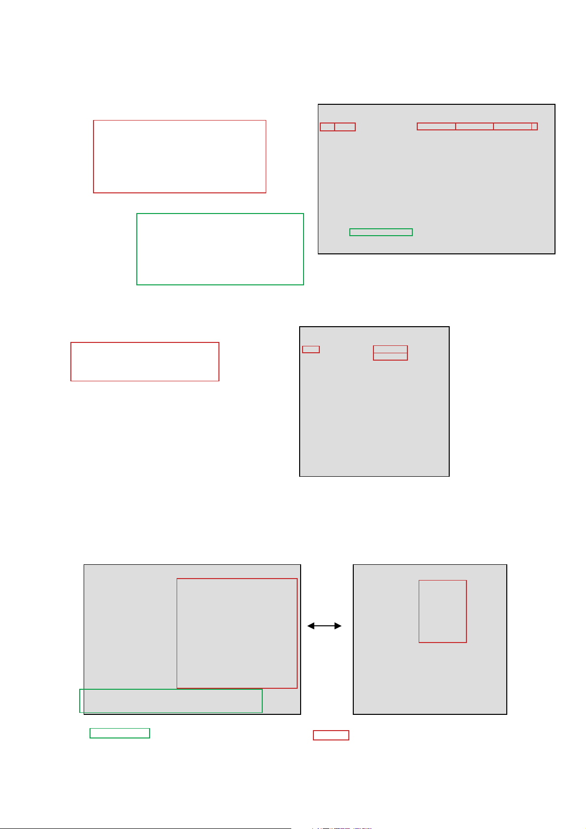
4. Self-diagnosis screen displays
-Incases of malfunctions where it is not possible to determine the symptom such as when
the power goes off occasionally or when the screen disappears occasionally, there is a
screen display on whether the malfunction occurred or not in the past (and whether the
detection circuit operated or not) in order to allow confirmation.
<Screen Display Method>
-Quickly press the remote command button in the following order from the standby state.
DISPLAY 5 - POWER
ChannelVol
Be aware that thisdiffers fro
the method of entering the
service mode (Vol +).
SELF CHECK(1)
002 LTEMP
003 LAMPC
004 FAN
005 LAMPD
006 POWER_ER
007 AUDIO
007 POWER_OV
009 DEMO
<1> Next Page -->
0000000000 0412311234 0501210811 0
0000000000 0000000000 0000000000 0
0000000000 0000000000 0000000000 0
0000000000 0000000000 0000000000 0
0000000000 0000000000 0000000000 0
0000000000 0000000000 0000000000 0
0000000000 0000000000 0000000000 0
0000000000 0000000000 0000000000 0
SELF CHECK(2)
TVM
WEM
DEM
EMMA
Page movement
TVM 00000-00000
WEM 00000-00000
DEM 00000-00000
EMMA 00000-00000
by <1> and <4>
<-- Prev Page <4>
00000000
00000000
00000000
00000000
00000000
00000000
00000000
00000000
– 14 –
Detail data (diagnosis history screen)
KDS-R60XBR2/R70XBR2
RM-YD009 RM-YD009
Trouble information
002: LED frequency
LTEMP: Item name
0311111825: Last failure time beforehand
0412311234: Failure time before last
0501210811: The last failure time
0 :Error count
Boot count and operation time
TVM: Microcomputer name
24 680
135- 79:
(ex.) Boot Count 13579 times
Operation time 24680 hours
Each max is 99999
An effective value only to DEM is displays
Detail data (device error display)
Trouble information
TVM: Micom name
0001FFFF: Present error information
80000000: Error information history
Anagram display of data
SELF CHECK(1)
002 LTEMP
003 LAMPC
004 FAN
005 LAMPD
006 POWER_ER
007 AUDIO
008 POWER_OV
009 DEMD
SELF CHECK(2)
TVM
WEM
DEM
EMMA
TVM 12345-67890
WEM 00000-00000
DEM 00000-00000
EMMA 00000-00000
<-- Prev Page <4>
0001FFFF
80000000
00000000
00000000
00000000
00000000
00000000
00000000
<1> Next Page -->
0311111825 0412311234 0501210811 0
0000000000 0000000000 0000000000 0
0000000000 0000000000 0000000000 0
0000000000 0000000000 0000000000 0
0000000000 0000000000 0000000000 0
0000000000 0000000000 0000000000 0
0000000000 0000000000 0000000000 0
0000000000 0000000000 0000000000 0
Deletion object
SELF CHECK(1)
002 TEMP
003 OVP
004 FAN
006 LOWB
007 AUDIO
009 PANEL
101 DTT WDT
102 TVM WDT
103 WEM WDT
104 DEM WDT
TVM 00000-00000
WE 00000-00000
DE 00000-00000
<1> NEXT PAGE->
0000000000 0412311234 0501210811 0
0000000000 0000000000 0000000000 0
0000000000 0000000000 0000000000 0
0000000000 0000000000 0000000000 0
0000000000 0000000000 0000000000 0
0000000000 0000000000 0000000000 0
0000000000 0000000000 0000000000 0
0000000000 0000000000 0000000000 0
0000000000 0000000000 0000000000 0
0000000000 0000000000 0000000000 0
0000000000 0000000000 0000000000 0
Deleted By TEST RESET
– 15 –
SELF CHECK(2)
TVM
WE
DE
<- PREV PAGE <4>
00 00 00 00
00 00 00 00
00 00 00 00
00 00 00 00
00 00 00 00
00 00 00 00
Deleted by <8> -> <0>

-The results display is not automatically cleared. In case of repairs and after repairs, chec
k
the self-diagnosis screen and be sure to return the results display to "0".
-Ifthe results display is not returned to "0" it will not be possible to judge a new malfunction
after completing repairs.
<Method of Clearing Results Display>
1. Power off (Set to the standby mode)
2. Channel Vol
3. Channel
<Method of Ending Self-Diagnosis Screen>
-When ending the self-diagnosis screen completely, turn the power switch OFF on the
remote commander or the main unit.
5. Self-Diagnosis function operation
80
DISPLAY 5 - POWER
2:Temp over When the inside temperature sensed with IC3150, IC3200 and IC2000
mounted on S1 board, S2 board and C board respectively exceed
the threshold, DEM (Display Engine u-com) detects it and makes
turn off the lamp.
3:Lamp cover When the lamp cover is opened or harness from T board is off, DEM detects it
and makes turn off the lamp
4:FAN error When any FAN is stopping or harness is not connected correctly,
DEM detects it and makes turn off the lamp
5:Lamp Driver When the ballast is not working with high voltage, DEM detects it and makes
turn off the lamp
6:Power error When 11V is low, TVM
(TV u-com) detects it and makes turn off the lamp.
7:Audio When DC is appeared by audio amp failure at speaker line, DEM detects it
and makes turn off the lamp.
8:Power-OVP When the output voltage from 11V is abnormally high, TVM detects
it and makes turn off the lamp.
9:Device error When the temperature sensor and bus decoder ICs do not return ACK on IIC
bus to DEM, DEM detects it and makes turn off the lamp.
LAMP : Lamp When the lamp is broken, DEM detects it.
KDS-R60XBR2/R70XBR2
RM-YD009 RM-YD009
– 16 –
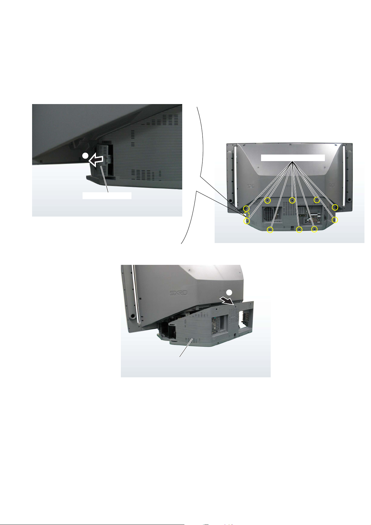
2-1. REAR COVER
SECTION 2
DISASSEMBLY
KDS-R60XBR2/R70XBR2
RM-YD009 RM-YD009
1
Lamp door assembly
2 10 screws (+BVTP 4x16)
3
Rear cover
– 17 –
2-2. CHASSIS ASSEMBLY
1 2 screws(+BVTP2 4x16)
R70XBR2 Model Only
2
5 2 screws(+BVTP2 4x16)
6 2 connectors
KDS-R60XBR2/R70XBR2
RM-YD009 RM-YD009
3 2 screws(+BVTP2 4x16)
9 Disconnect connectors
1 2 screws(+BVTP2 4x16)
R70XBR2 Model Only
8 Wire holder
9 Disconnect connectors
7 Screw (+BVST 3x6)
0 Loosen wire holder
4 Side stay (R)
5 4 screws (+BVTP2 4x16)
qa Disconnect connectors
qs Slide out the chassis block
– 18 –

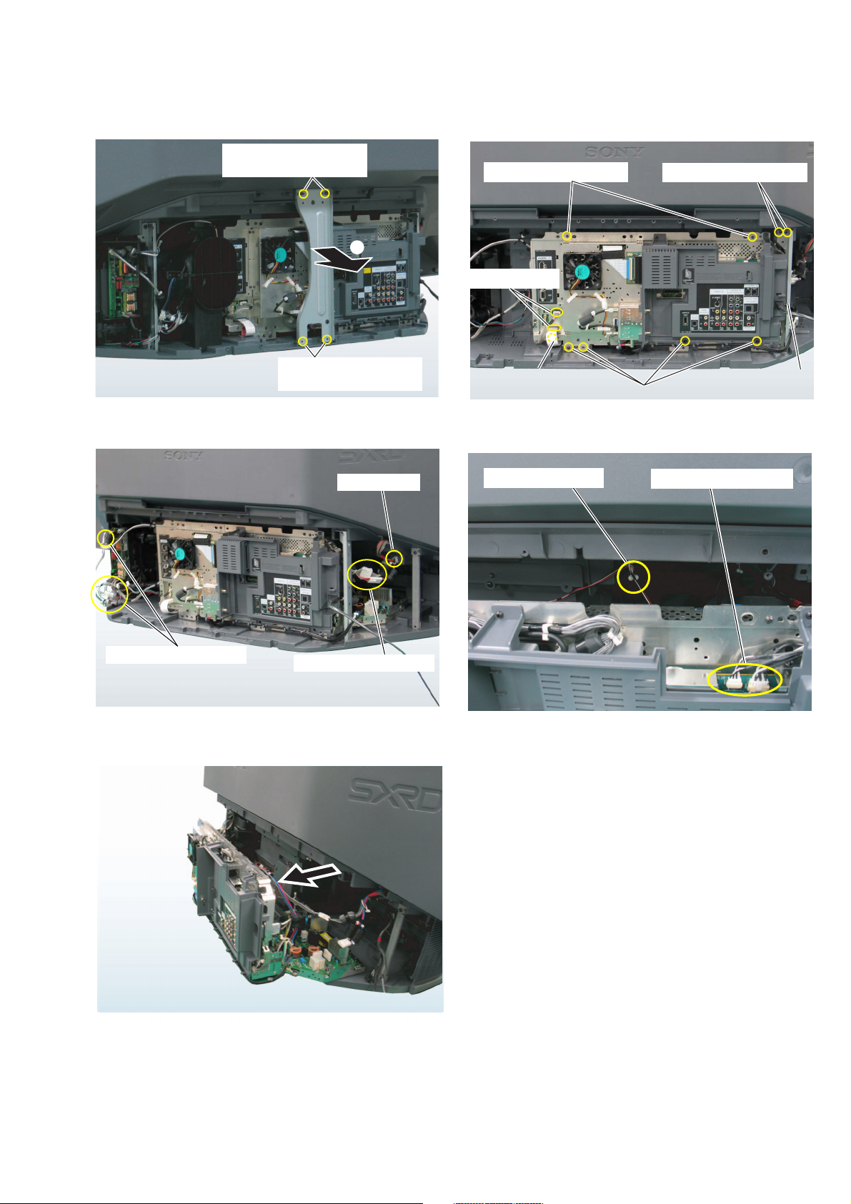
2-3. TERMINAL BRACKET
1 2 screws(+BVST3x6)
3 2 screws(+BV3x12)
KDS-R60XBR2/R70XBR2
RM-YD009 RM-YD009
2 2 nuts
2-4. UU BOARD
1 2 screws(+BVST3x6)
1 2 screws (+BVST3x6)
1 2 screws (+BVST3x6)
4 Terminal bracket
2 2 screws (+BVST3x6)
3 UU board
2 2 screws (+BVST3x6)
S1 board
2-5. S1 BOARD
On removing or attaching UU board,
Be careful about the connector on back.
1 Screw (+BVST3x6)
2 S1 board
– 19 –
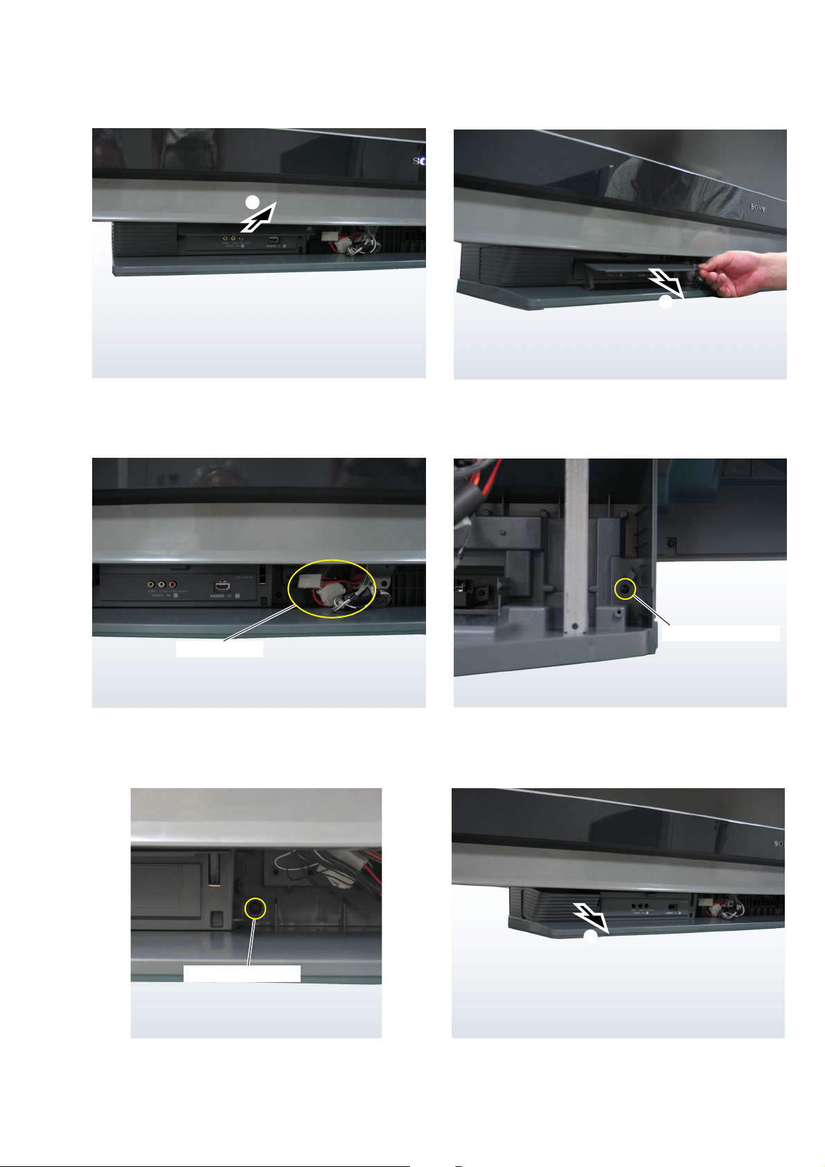
2-6 QM, QT BOARDS
1 2 screws (+BVST3x6)
1 2 screws (+BVST3x6)
KDS-R60XBR2/R70XBR2
RM-YD009 RM-YD009
FE shield assembly
2 Connector
3
QT Board
QM board
4 4 screws (+BVST3x6)
On removing or attaching QM board,
Be careful about the connector on back.
5 QM board
6 2 screws (+BVST3x6)
8
7 2 screws (+BVST3x6)
– 20 –

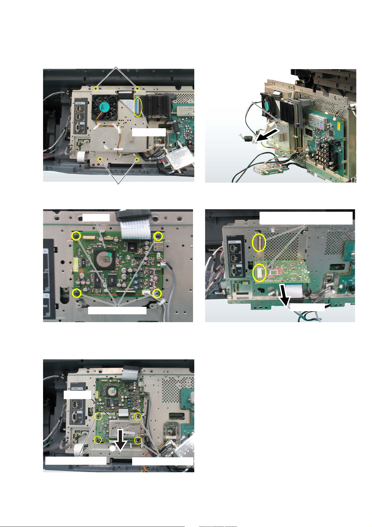
2-7. AU, B2 BOARDS, G BLOCK ASSEMBLY
Main shield
G block
assembly
8
3 2 screws (+PSW M 3x5)
KDS-R60XBR2/R70XBR2
RM-YD009 RM-YD009
2 2 screws
(+BVST3x6)
4 2 screws
(SP 4-40 UNC)
B2 board
1 Screw (+BVST3x6)
2 5 screws (+BVST3x6)
6 4 screws (+BVST3x6)
AU board
5
Main shield (lid)
Be carefull to remove
the main shield (lid).
Because this groove is
caught in G block assembly.
7
6
AU board
Main shield
6 6 screws (+BVST3x6)
9
8 2 screws (+BVST3x6)
B2 board
Disconnect from
G board
These boards are connected in the center.
So, be carefull about it.
– 21 –
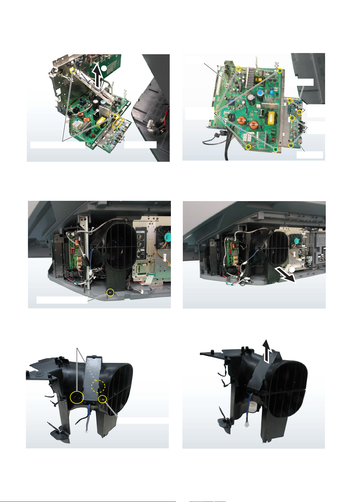
2-8. G, H3U, PH BOARDS
2
KDS-R60XBR2/R70XBR2
RM-YD009 RM-YD009
G board
3
PH board
1 2 screws (+BVST3x8)
2-9. DC MOTOR SFF21C/C-NP
2 Connector
1 4 screws
(+BVST3x6)
2 2 screws
(+BVST3x6)
3 2 screws
(+BVST3x6)
H3U board
1 Screw(+BVTP4x16)
4 2 Claws
5
3 Screw(+BVTP4x16)
– 22 –
DC motor SFF21C/C-NP
KDS-R60XBR2/R70XBR2
RM-YD009 RM-YD009
2-10. POWER SUPPLY BLOCK
1 Screw(+BVTP4x16)
2 Screw(+BVTP4x16)
2-11. DC MOTOR SFF25A/C-NP
3 Screw(+BVTP4x12)
4
5 Screw(+BVTP4x16)
– 23 –

2-12. DC MOTOR SFF24A/C-NP
KDS-R60XBR2/R70XBR2
RM-YD009 RM-YD009
7
6 Claw
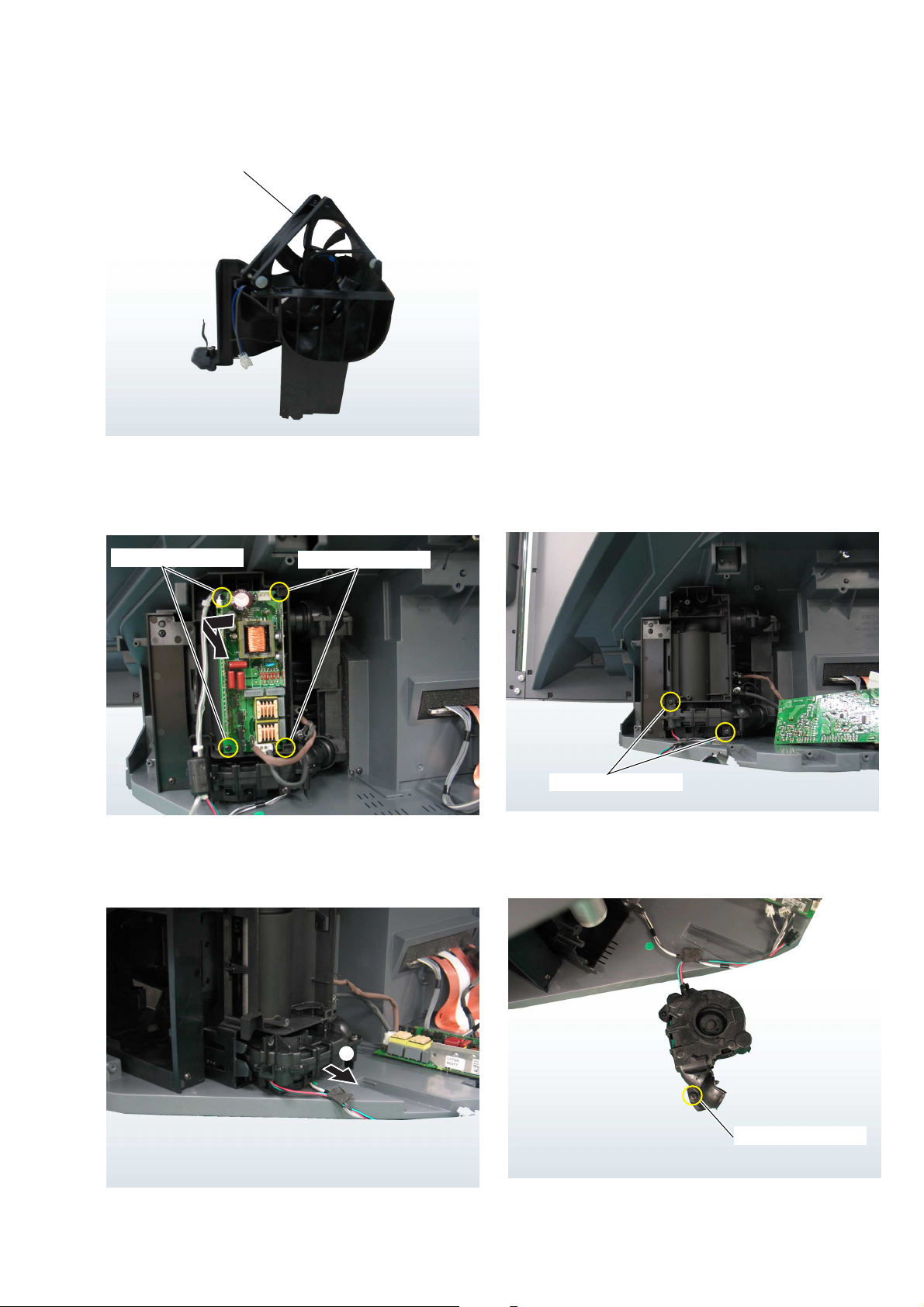
2-13. COVER UNIT
1 2 screws (+BVTP2 4x16)
3 Scirocco fan
(DC motor SFF24A/C-NP)
2
Scirocco fan cover
Cover unit
1 7 screws
(+BVTP2 4x16)
2 Cover unit
– 24 –

2-14. LAMP GUIDE (F)
1 2 screw(+BVTP4x16)
KDS-R60XBR2/R70XBR2
RM-YD009 RM-YD009
3 2 claws
4
2
5 3 screw(+BVTP4x16)
2-15. SCREEN FRAME BLOCK ASSEMBLY
6
2
1 Screw(+BVTP4x16)
– 25 –
3
KDS-R60XBR2/R70XBR2
RM-YD009 RM-YD009
4
Pull it forward picking both
ends of the door.
5 3 connectors
7 Screw(+BVTP4x16)
6 Screw(+BVTP4x16)
8
– 26 –
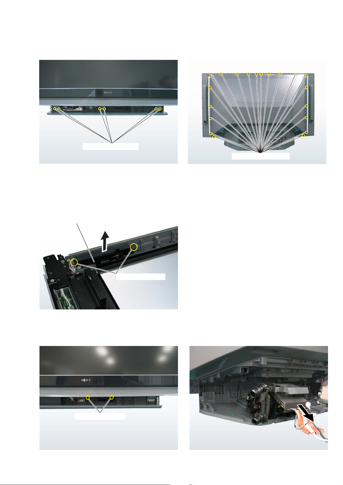
9 6 screws(+BVTP4x16)
Note:Removethe screw from the under.
KDS-R60XBR2/R70XBR2
RM-YD009 RM-YD009
0 20 screws(+BVTP4x16)
2-16. H1 BOARD
H1 board
2
1 Screw(+BVTP4x16)
2-17. OPTICS BLOCK ASSEMBLY
1 Screw(+BVTP4x16)
2
– 27 –

KDS-R60XBR2/R70XBR2
RM-YD009 RM-YD009
2-18. MIRROR COVER BLOCK ASSEMBLY
R70XBR2 Model Only
1 5 screws(+BVTP4x16) 1 5 screws(+BVTP4x16)
2-19. T1,S2 BOARD
S2 board
1 Screw(+BVTP4x16)
T1 board
S2 board
2
T1 board
– 28 –
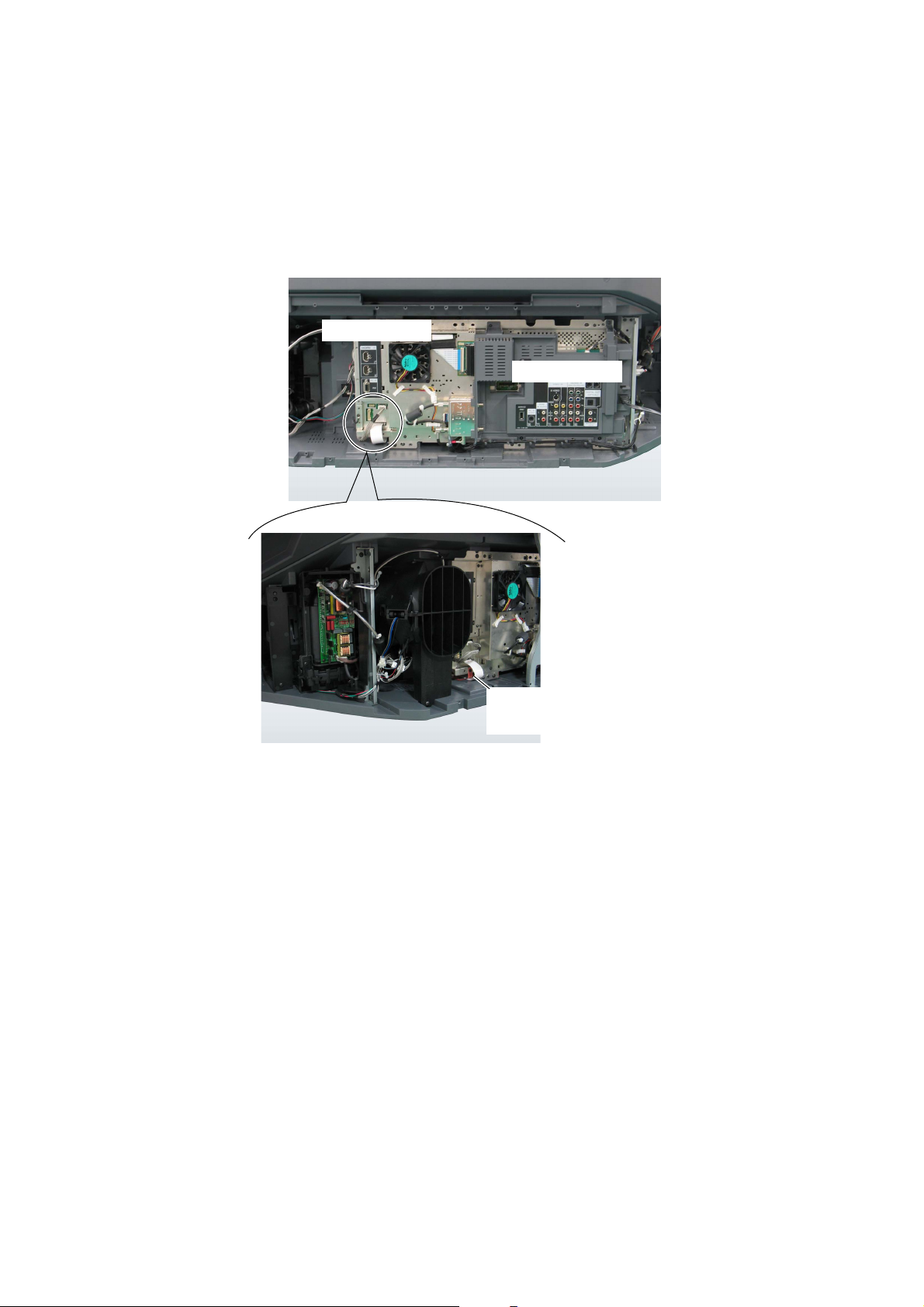
2-20. NOTES ON HARNESS ARRANGEMENT
There is no leads to be caught.
Chassis assembly should be atached gradually with managing leads.
Bottom assembly
KDS-R60XBR2/R70XBR2
RM-YD009 RM-YD009
Chassis assembly
The shield and leads from C board come out
from here.
* Be sure not to break the lead.
– 29 –
SECTION 3
ELECTRICAL ADJUSTMENTS
3-1. ELECTRICAL ADJUSTMENT BY REMOTE
COMMANDER
By using remote commander (RM-GA006), all circuit adjust-
ments can be made.
NOTE : Test Equipment Required.
1. Pattern Generator (with component outputs)
2. Oscilloscope
3. Digital multimeter
3-1-1. Method of Setting the Service Adjustment
Mode
1. Standby mode. (Power off)
2. DISPLAY t 5 t VOL (+) t TV POWER
on the remote commander.
(Press each button within a second.)
The following service screen will appear.
Mode
TVM Service Menu SERVICE
XXX VERSION
XXX VERS XXX
<Digital> Program
Boot : X.X.XX
Program : X.XXX
<TV>
Data : X.XXX
Boot : X.XXX
Program : X.XXX
<WE>
Data : X.XXX
Boot : X.XXX
Program : X.XXX
<DE>
Data : X.XXX
Boot : X.XXX
Category Name
Item No.
Sub Item No.
Category Name
Item Name
: X.XX.XXX
Item Name
PANEL SERVICE
0 OP MODE
0T1 5
DIFF 1 50Hz
Data
KDS-R60XBR2/R70XBR2
RM-YD009 RM-YD009
3-1-2. Service Mode Adjustment
1. The SCREEN displays the item being adjusted.
2. Press “1” or “4” on the remote commander to select the
adjustment item.
3. Press “3” or “6” on the remote commander to change the data.
4. Press “2” or “5” on the remote commander to select the category.
Every time you press “2” (Category up), Service mode
changes in the order as shown below.
Key
TVM Service Menu
JUMP
WEM VERSION
JUMP
PANEL SERVICE
0 OPMODE
1 TG
2
2 WB
2
3 CSC
2
4 HUE
2
5 TEST_PAT
: :
: :
34 LUM
2
0 OPMODE
: :
5. If you want to recover the latest values press “-” then
“[ENTER]” to read the memory.
6. Press “[MUTING]” then “[ENTER]” to write into memory.
7. Turn power off.
<Method of setting the shipping condition>
1. Service Adjustment mode.
2. Press “8” then “[ENTER]”
3. Wait until appearing “ Initial Setup” display.
4. Disconnect AC plug and connect again to change factory re-
set condition completely.
Sub Item Name
<DISPLAY ENGINE>
3-1-3. Memory Write Confirmation Method
1. After adjustment, turn power off with the remote commander.
2. Turn power on and set to service mode.
3. Call the adjusted items again and confirm they were adjusted.
– 30 –-
 Loading...