

Sony KDL-43W660F, KDL-43W667F, KLV-43W662F, KLV-50W662F, KDL-50W667F Service Manual
...
SERVICE MANUAL (UNIQUE)
Version Date Subject
1 02/2018 1st Issue
2 04/2108 Add destination HK5, PL1 & TW6 (pg.48, 51, 53, 56)
3 04/2018 Correct model name for TW6 and PL1 (pg.3)
4 05/2018 1. Add destination IN5 for CTTI plant (pg.48, 51, 53, 56)
2. Update board name LKP1 --> LKP2 for 50” (pg.13)
5 05/5/2018 1. Add destination E41 (pg. 3, 48, 51, 53, 56)
2. Correct Sheet Thermal(BM) part number for HK5, TW6, PL1 (pg. 48)
3. Correct ASSY,FALL LOCK,BELT LL part number for HK5, TW6, PL1 (pg. 51)
4. Correct CORD SET, POWER-SUPPLY part number for HK5 (pg. 51)
ORIGINAL MANUAL ISSUE DATE:
GN4 CHASSIS
Segment : CP
HISTORY INFORMATION FOR THE FOLLOWING MANUAL:
LCD TV
9-888-746-P5
For SM - Common , please refer :
9-888-746-0x
SYSSET
2018/06/1909:29:32(GMT+09:00)

SERVICE MANUAL (UNIQUE)
LCD TV
GN4 CHASSIS
Segment : CP
SYSSET
2018/06/1909:29:32(GMT+09:00)
MODEL LIST
MODEL
REMOTE DESTINATION
KLV
-43W662F
KDL
-43W660F
RMT-TX301P
RMT-TX300E
RMT-TX300P
IN5
AZ1
AF1, E51, IA2, MY1,
TH8,HK5,
VN3, E41
RMT-TX300T
TW6
KDL
-43W667F RMT-TX300P
PL1
KLV
-50W662F
KDL
-50W660F
RMT-TX301P
RMT-TX300E
RMT-TX300P
IN5
AZ1
AF1, E51, IA2, MY1, TH8, VN3, E41
RMT-TX300T
TW6
KDL
-50W667F
RMT-TX300P
PL1
SYSSET
2018/06/1909:29:32(GMT+09:00)
Section Title
Page
1.
SAFETY NOTES
1
-1.
How to Remove Rear Cover ..………………………...…..
5
2.
DIAGRAMS
2
-1.
Circuit Board
Location …..………………...…………….. 13
2
-2.
Wire
Dressing ………………………………………………. 14
3. DISASSEMBLY, EXPLODED VIEWS AND OTHER PARTS
3
-1.
KDL
-43W66*F/KLV-43W66*F………………………………… 47
3
-2.
KDL
-43W66*F/KLV-43W66*F ……………..………………… 52
4
TABLE OF CONTENTS
Please refer Service Manual – Common for below information :
General Safety Notes
Self Diagnostic Function
Triage Chart
Troubleshooting, Troubleshooting reference
Adjustments
Diagrams : Block Diagram , Connector Diagram
Panel Handling
Note: Pictures provided in all this manual might have slight difference from
the actual sets
SYSSET
2018/06/1909:29:32(GMT+09:00)
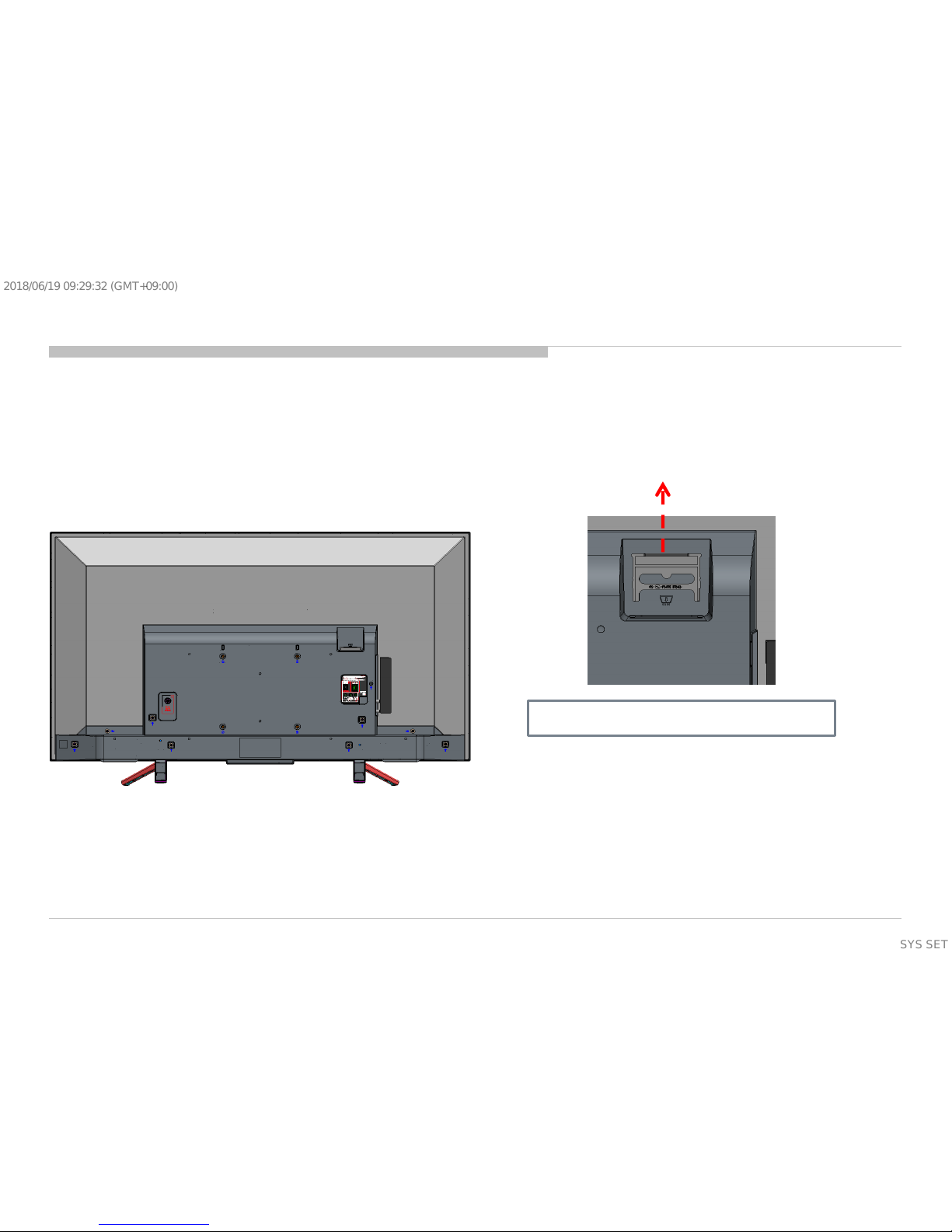
RC Disassembly method and caution
1.Dummy Card PCMCIA dismantle guide (before removing rear cover)
Pull up dummy card PCMCIA
SECTION 1
DISSASSEMBLY AND REMOVAL CAUTION
5
SYSSET
2018/06/1909:29:32(GMT+09:00)
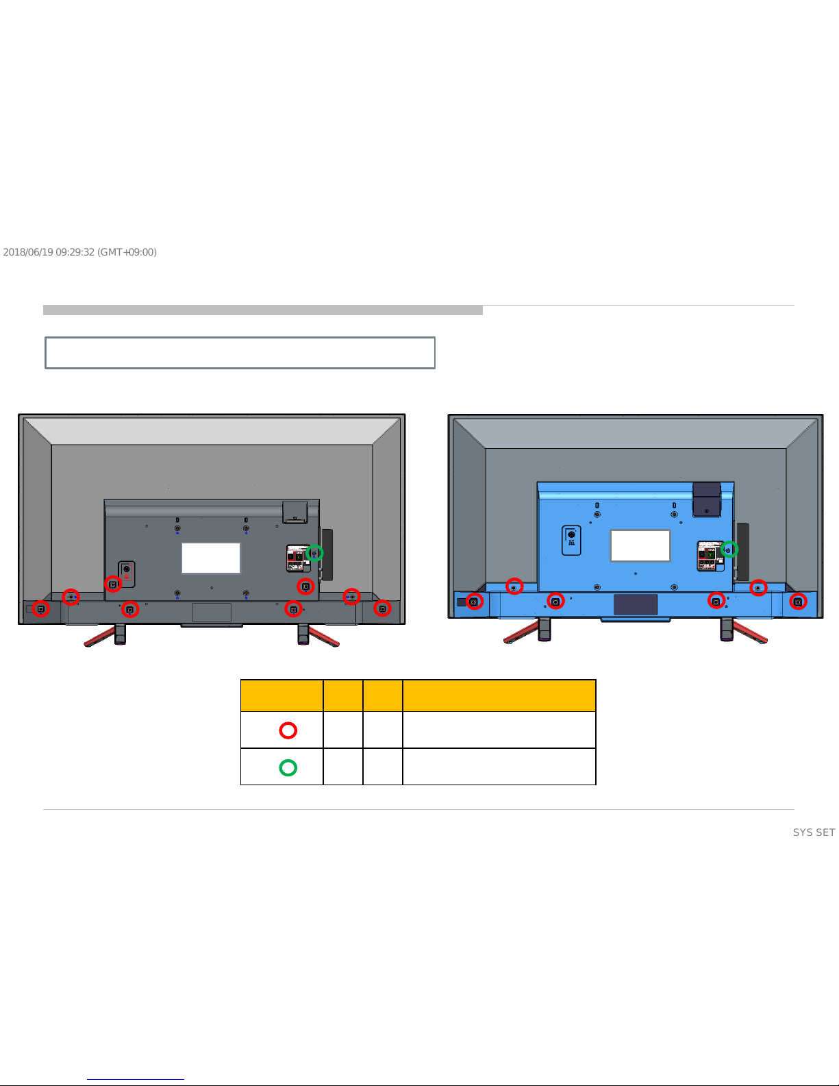
Reference 43” 50” Remarks
6 8 4-167-019-22
Screw, +PSW M3X8
1 1 7-685-647-79
Screw, +BVTP 3X10 Type 2 IT-3
1. Screw type & qty to disassemble RC
50”
43”
RC Disassembly method and caution
6
SYSSET
2018/06/1909:29:32(GMT+09:00)
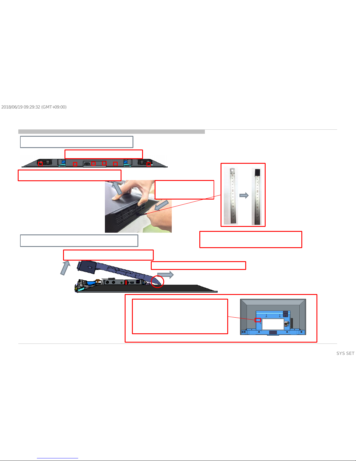
2. Disassemble bottom hook
a. Confirm hook position
b. 1 hand hold top RC to unhook
c. 1 hand push
ruler to insert at
hook area
Note: Please wrap end of ruler with
tape to avoid part scratch/damage
3. Disassemble the rear cover
a. Lift the bottom rear cover up
b. Release the rear cover from set
Note: for 43” only, please
push red area while (a. lifting
the bottom rear cover up).
Purpose is to release 43” side
hook.
43”
RC Disassembly method and caution
7
SYSSET
2018/06/1909:29:32(GMT+09:00)
Sharp Edge Information
Caution Point:
Please wear glove while removing rear cover to avoid sharp edge
At bottom area as shown in figure below.
Sharp edge corner Sharp edge corner
8
SYSSET
2018/06/1909:29:32(GMT+09:00)
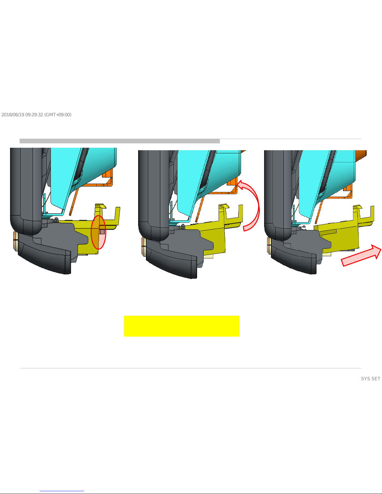
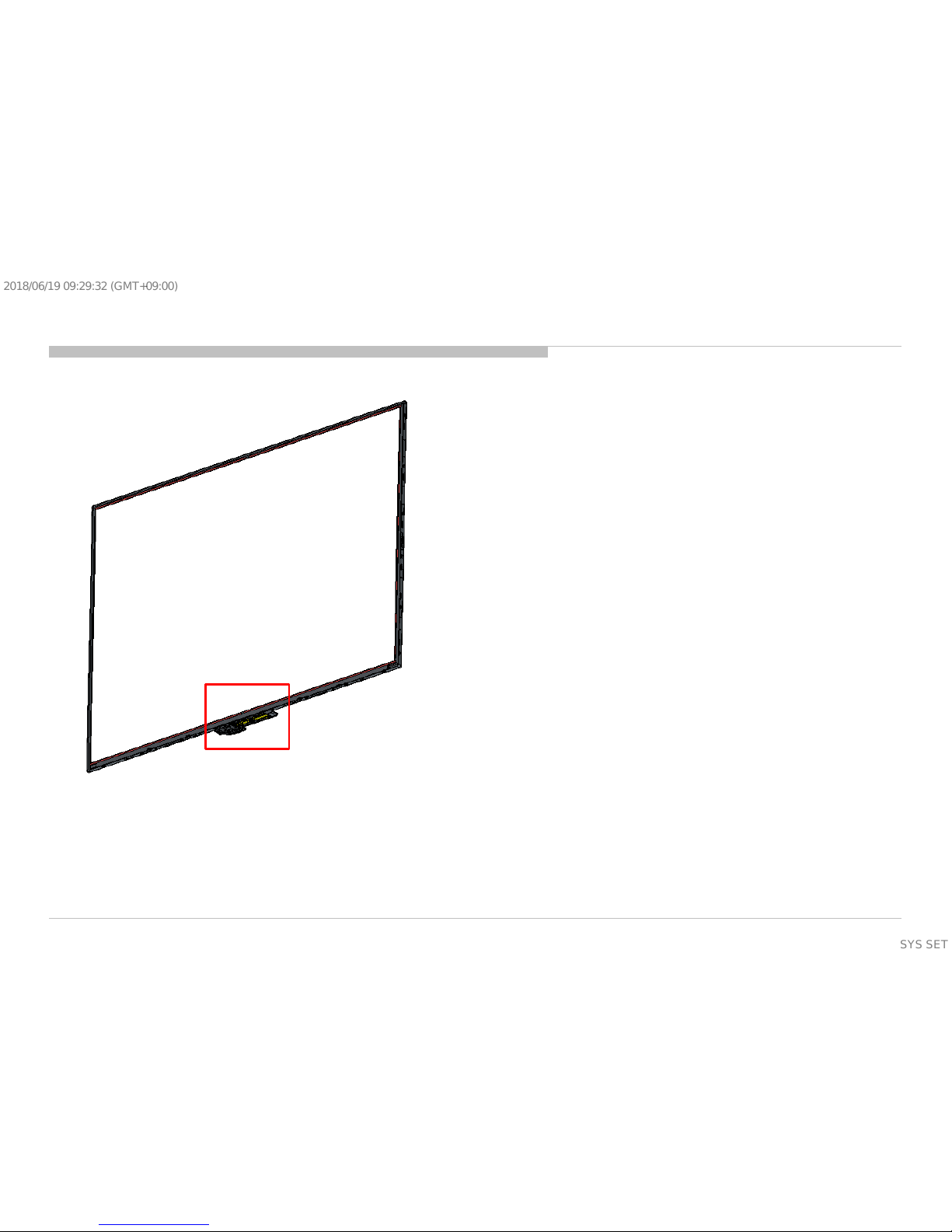
Method 1: Disassemble In Set Condition
1. Hold the end of Guide Light
2. Rotate Guide Light slightly
3. Pull Guide Light out
Note:
1. Ensure Hook is not broken
2. Prepare replaceable new part in case hook broken
Hold here for
both L&R sides
9
SYSSET
2018/06/1909:29:32(GMT+09:00)
Method 2: Disassemble Bezel First
Step 1: Disassemble entire Bezel from P-mod/Set
together with guide light (PTT) A attached.
10
SYSSET
2018/06/1909:29:32(GMT+09:00)

Step 2: Use a jig or pen to press on this hook area
while pull the guide light (PTT) A out
Press this hook area here
Pull guide light out
Step 3: Repeat Step 2 at this circled area
also
Press this hook area here
Method 2: Disassemble Bezel First
11
SYSSET
2018/06/1909:29:32(GMT+09:00)
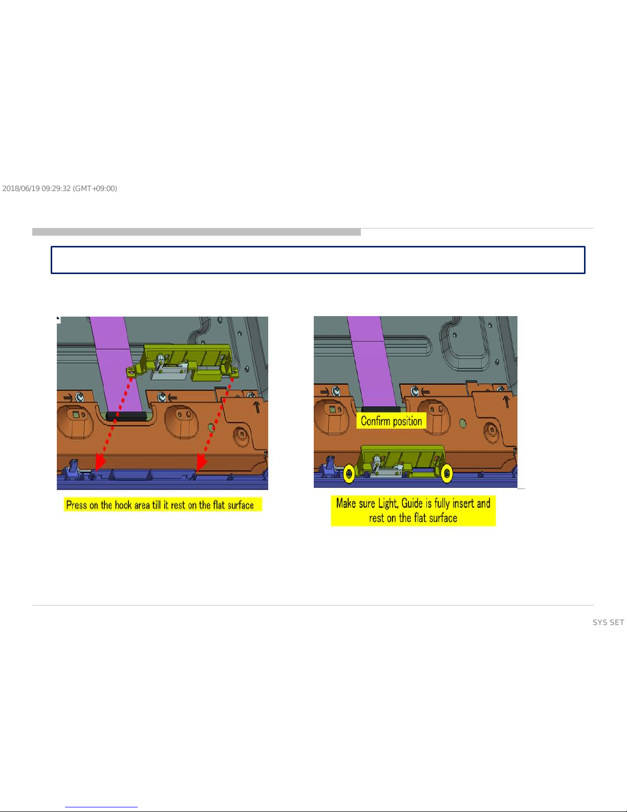
It is difficult to remove the Light Guide from Bezel Lock (Hook) without damaging the Hook.
12
SYSSET
2018/06/1909:29:32(GMT+09:00)
SECTION 2
DIAGRAMS
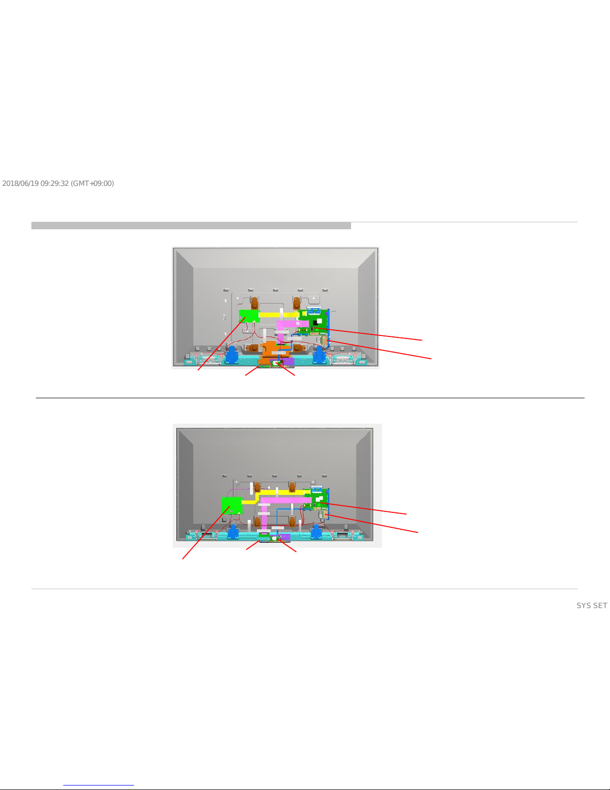
2.1 Circuit Board Location
2-1-1. 43”
2-1-2. 50”
SWITCH
UNIT
UNIVERSAL SIL-TU
BPA BOARD
LKP1 BOARD
CARD, WIRELESS LAN
SWITCH
UNIT
UNIVERSAL SIL-TU
BPA BOARD
LKP2 BOARD
CARD, WIRELESS LAN
13
SYSSET
2018/06/1909:29:32(GMT+09:00)
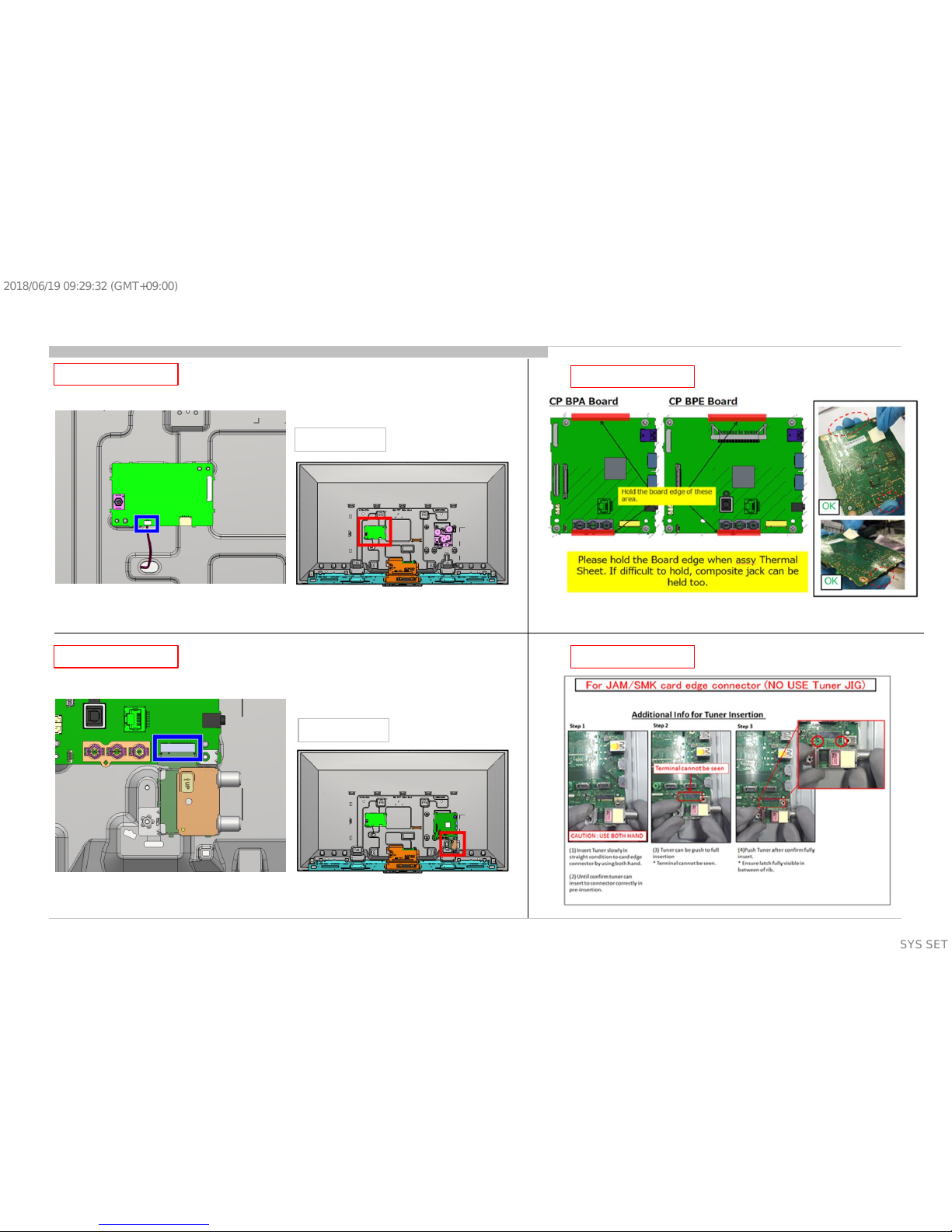
2.2 Wire Dressing 43”
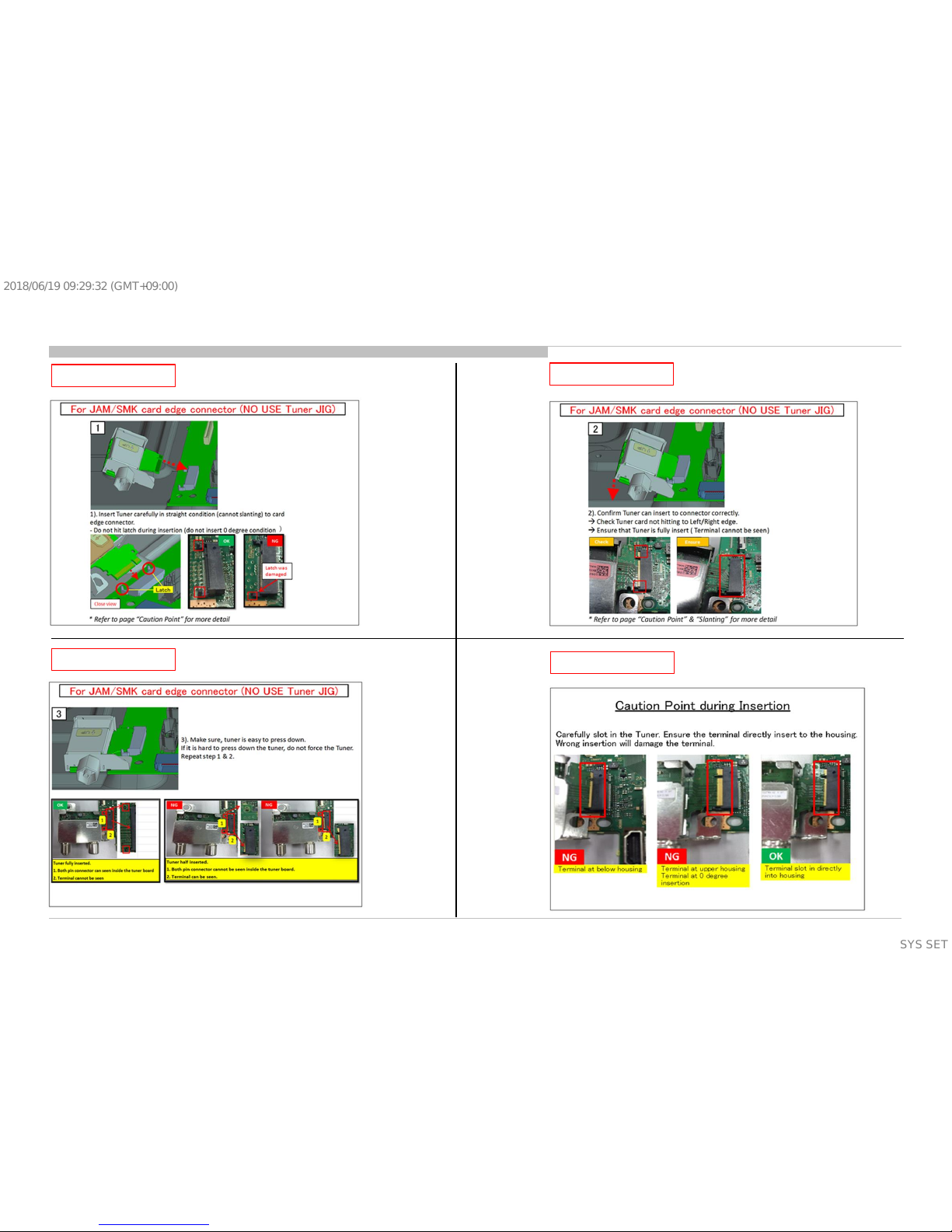
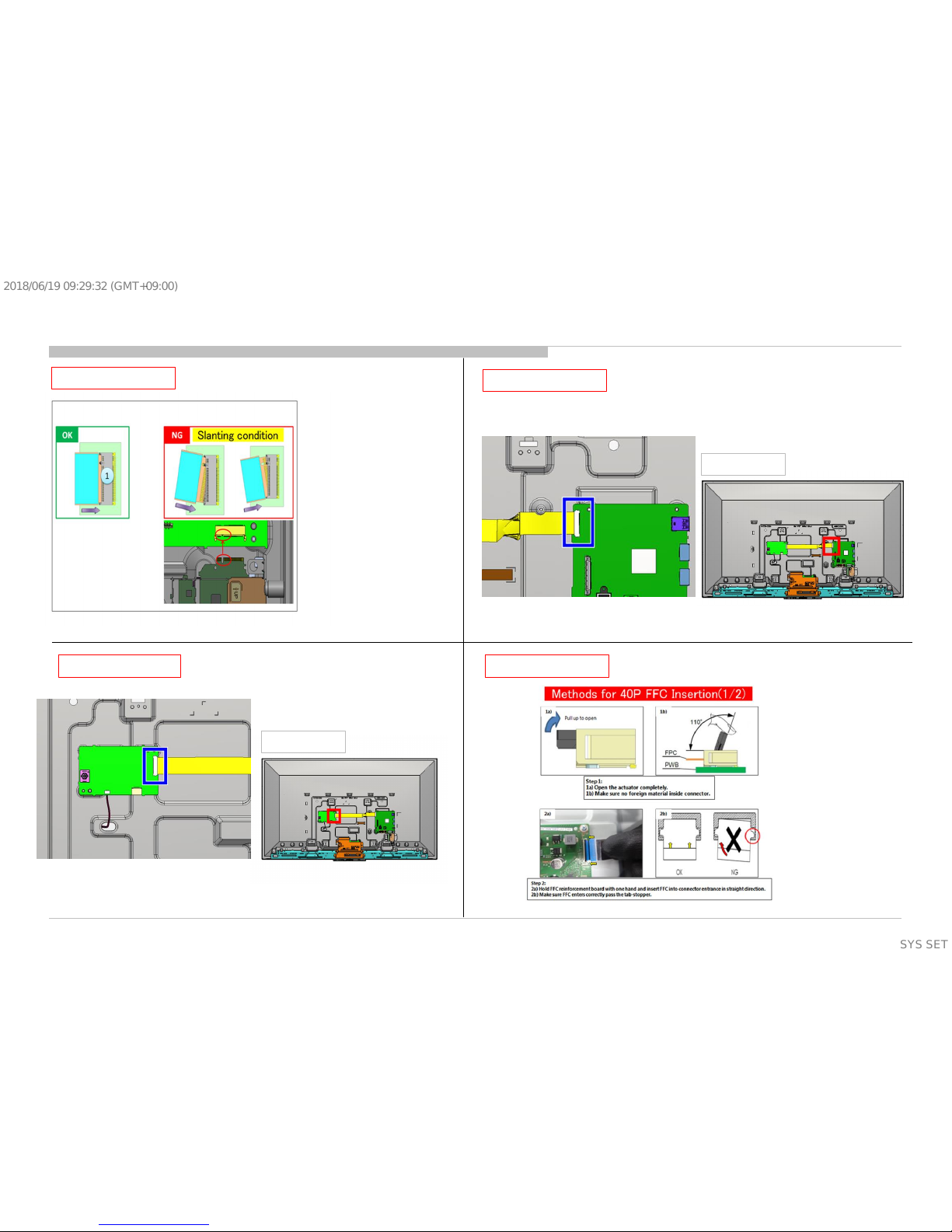
CONNECT
INFORMATION
CONNECT
14
Overall View
Overall View
INFORMATION 1
SYSSET
2018/06/1909:29:32(GMT+09:00)
INFORMATION 2
INFORMATION 3
INFORMATION 4
INFORMATION 5
15
2.2 Wire Dressing 43”
SYSSET
2018/06/1909:29:32(GMT+09:00)
INFORMATION 6
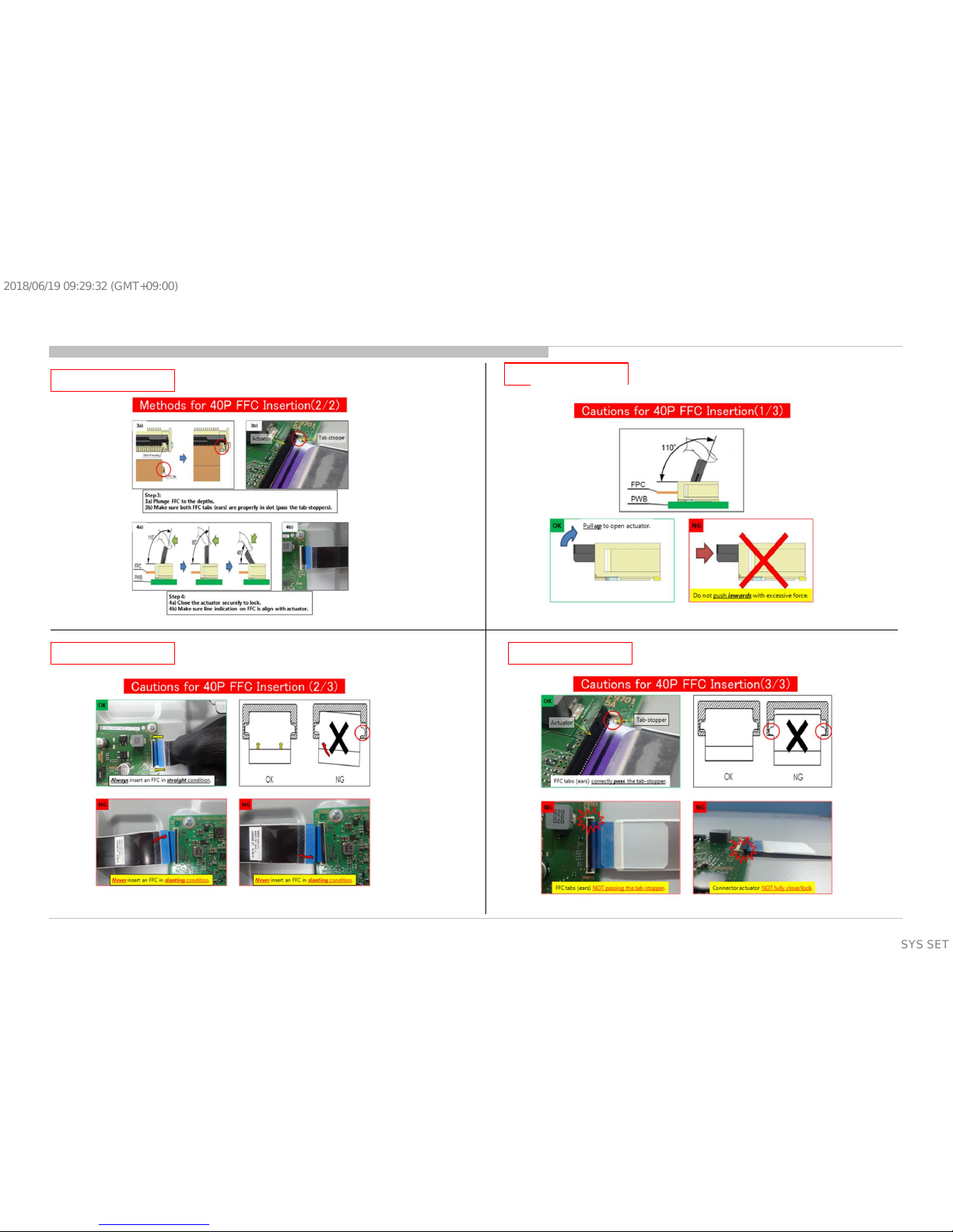
CONNECT 40P
INFORMATION 1 CONNECT
16
Overall View
Overall View
2.2 Wire Dressing 43”
SYSSET
2018/06/1909:29:32(GMT+09:00)
INFORMATION 3
INORMATION 4
17
INFORMATION 2
INFORMATION 5
2.2 Wire Dressing 43”
SYSSET
2018/06/1909:29:32(GMT+09:00)
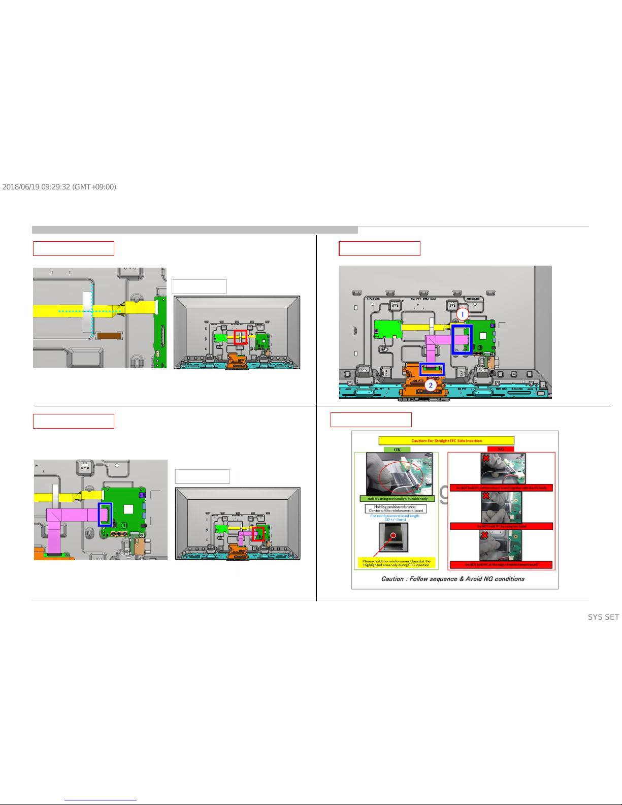
TAPE
CONNECT 51P
INFORMATION 51P
INFORMATION 1
18
Overall View
Overall View
2.2 Wire Dressing 43”
SYSSET
2018/06/1909:29:32(GMT+09:00)
 Loading...