

Sony KDL-48W580B, KDL-48W585B, KDL-60W600B, KDL-40W590B, KDL-60W605B Service Manual
...
Version Date Subject
1 01/2014 1st Issue.
2 04/2014 Model Addition : Add 60” Models ( Model List , pg 45-46 )
LCD TV
9-888-150-02
For SM - Unique , please refer :
9-888-150-A1 ( America )
9-888-150-C1 ( China)
9-888-150-E1 ( Europe )
9-888-150-P1 ( Pan Asia )
HISTORY INFORMATION FOR THE FOLLOWING MANUAL:
RB2G CHASSIS
Segment: HM
SERVICE MANUAL (COMMON)

LCD TV
SERVICE MANUAL (COMMON)
RB2G CHASSIS
Segment: HM
3
MODEL LIST
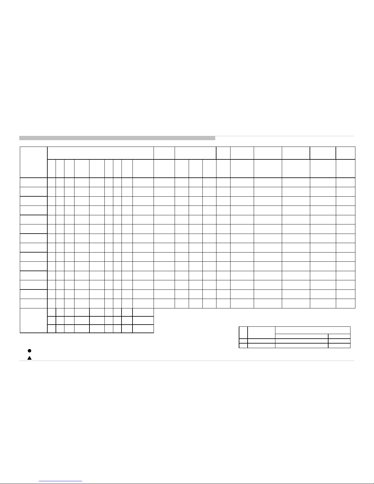
THIS SERVICE MANUAL CONTAINS COMMON INFORMATION FOR BELOW REGIONS AND MODELS:
REGION
ASIA CHINA AMERICA JAPAN EUROPE
MODEL
KDL-40W580B KDL-48W580B
KDL-60W600B
KDL-40W590B KDL-48W585B
KDL-60W605B
KDL-40W600B KDL-48W590B
KDL-60W607B
KDL-40W605B KDL-48W600B
KDL-60W608B
KDL-40W607B KDL-48W605B
KDL-60W610B
KDL-40W608B KDL-48W607B
KDL-60W630B
KDL-48W608B
KDL-60WM15B
KDL-48WM15B
Sectio n Title Page
1. SAFETY NOTES
1-1. Warnings and Caution………………………………… …………………… . 5
1-2. Caution Handling of LCD Panel ......…………….................................... 5
1-3. Caution About the Lithium Battery………………………………………….. 6
1-4. Safety C he ck Ou t ........................……………......................................... 6
1-5. Leakage Test .......................................................................................... 6
1-6. How to Find a Good Earth Ground………………………………………… 7
1-7. Lead Free Information….…………………………………………………… 7
1-8. Handling the Flexible Flat Cable (FFC)……………………………………. 7
2. SELF DIAGNOSTIC FUNCTION
2-1.
Overvie w o f Co ntrol B utto ns ........ ... ... . .... . .... .. ... .. ... .. ... .. ... .. .... . .... . .... .. ... ..
8
2-2. LED Display Control ………..................................................................... 9
2-3. LED Pattern………………........................................................................ 9
2-4. Standby LED Error Display…………………………………………………. 9
2-5. Triage Chart ............................................................................................ 10
3. TROUB LE S H OOTIN G
3-1. No Power…….……………………………………………………………….. 11
3-2. LED Blinking……………….………………………………………............... 12
3-3. No Sound……………………………......................................................... 20
3-4. No Picture................................................................................................. 21
3-5. Side Buttons Malfunction……………………………………………………. 23
3-6. IR Remote Commander Malfunction……………………………………… 23
3-7. Light Sensor Error……………………………… ………… ……………… . 23
3-8. Network Malfunction: Ethernet (Wired)………………………… …………. 24
3-9. 3D-Glasses (Active) malfunction…………………… …… ………… …….. 25
3-10. Wireless Network Malfunction……………………………………… ……. 26
3-11. Bluetooth Malfunction……………………………………………………….. 27
4
TABLE OF CONTENTS
Please refer Service Manual – Unique for below information :
-Safety Warnings
-Wire Dressing
-Circuit Board Location
-Disassembly and Exploded View.
Sectio n Title Page
4. SERVICE ADJUSTMENTS
4-1. Accessing Service Mode ..................................................................... 28
4-2. Transition of Each Micro’s S ervice Mode……….……………………… 28
4-3. Change Data by Service Mode 1………………………………… ..……. 28
4-4. Change Data by Service Mode 2……………………… …… …………... 29
4-5. Restore WB / Gamma Adj. Data to B Board.………………………….. 30
4-6. WB Adjustment by Service Mode……………………………………….. 31
4-7. VCOM Adjustment (NFR-AUO/SDC/FXC Pane l) …………………………… 31
4-8. VCOM Adjustment (HFR-AUO /FXC Panel) …………………………………. 32
4-9. REC Setting………………………………………................................... 32
4-10. Reset Panel Operation Time…………………………… ………….... ..... 33
4-11. Set to Shipping Condition……………………………………….............. 33
4-12. Summary of Service Control……………………………………….......... 33
4-13. Service Menu Tree………………………………………... ........... ........ .. 34
4-14. How to Enter Self Diagnosis Display…………………………………… 35
5. DIAGRAMS
5-1. Circuit Board Location ......................................................................... 38
5-2. Block Diagram...................................................................................... 39
5-3. Connector Diagram ………………………………………...................... 44
RB2G CHASSIS
W580B/W585B/W590B/W600B/W605B/W607B/W608B/WM15B
1-2. Caution Handling of LCD Panel
When r epair ing the LCD Panel, make sure you are grounded w ith a wrist band.
When r epair ing the LCD Panel on the wall, the panel must be secured using the
4 mounting holes on the rear cover.
1) Do not press the panel or frame edge to avoid the ri sk of electri c shock.
2) Do not scratch or press on the panel wi th any sharp objects.
3) Do not leave the module in high temperature or in areas of high humidi ty for
an extended period of time.
4) Do not expose the LCD panel to direct sunli ght.
5) Avoid contact wi th water. I t may cause shor t cir cuit withi n the module.
6) Disconnect the AC power when repl acing the backl ight (CC FL) or
inverter ci rcu it. ( High voltage occu rs at the inve rter cir cuit at 650Vrms)
7) Always clean the LCD panel with a soft cloth m ateri al.
8) Use care when handling the wi res or connectors of the inve rter cir cuit.
Damaging the wires may cause a short ci rcui t.
9) Protect the panel from ESD to avoid damaging t he electr onic circuit (C-MOS).
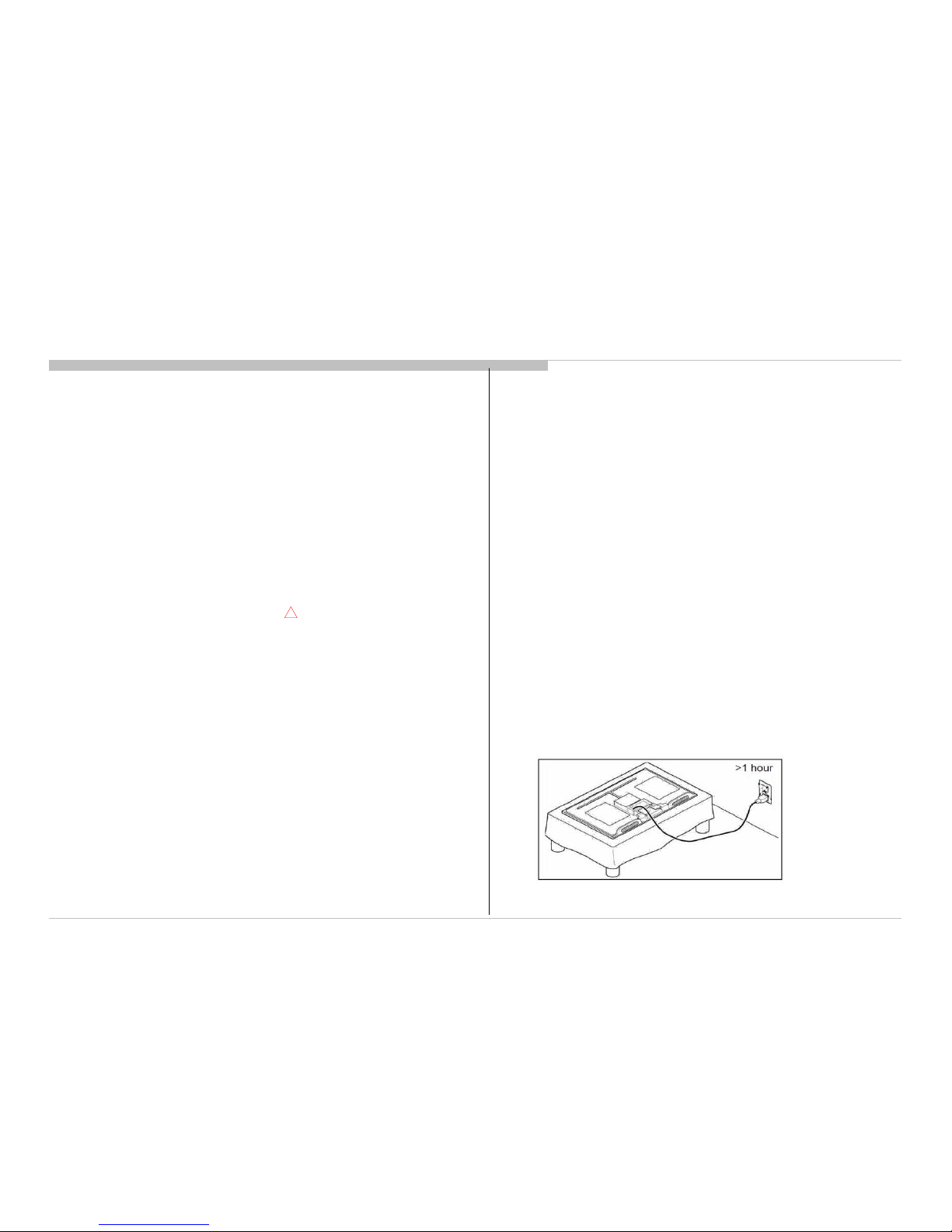
10) During t he r epai r , D O N OT l eave t he Pow er On or Bur n-i n period for more
than 1 hour whi l e the T V i s face dow n on a cl ot h.
5
SAFE TY NOTES
SECTION 1
1-1. Warnin gs and Caution
1) These servicing instructions are for use by qualified service personnel only.
2) To reduce the risk of electric shock, do not perform any servicing other than
that contained in the operating instructions unless you are qualified to do so.
3) An isolation transformer should be used during any service to avoid
Possible shock hazard, because of live chassis. The chassis of this receiver is
directly connected to the ac power line.
4) Be sure to follow these guidelines to protect your property and
avoid causing serious injury :
• Carry the TV with an adequate number of people; larger size TVs require
two or more people.
• Correct hand placement while carrying the TV is very important for
safety and to avoid damages.
5) Components identified by shading and mark on the exploded views,
and in the parts list are critical for safe operation. Replace these
components with Sony parts whose part numbers appear as shown in this
manual or in supplements published by Sony. Circuit adjustments that are
critical for safe operation are identified in this manual. Follow these
procedures whenever critical components are replaced or improper
operation is suspected.
!
Figure 1. TV is faced down on a cloth during repair.
RB2G CHASSIS
W580B/W585B/W590B/W600B/W605B/W607B/W608B/WM15B
6
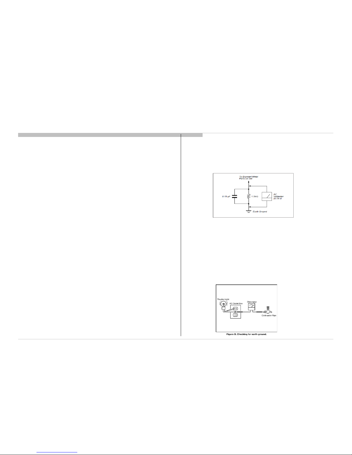
3) Measuri ng the voltage drop acr oss a resistor by means of a VOM or battery
operated AC voltmeter. The 'l im it' indication i s 0.75V so analog meter s must
have an accurate low voltage scal e. The SIM PSO N'S 250 and SANWA SH63TRD are examples of passive VOMs that are su itabl e. Nearl y all battery
operated digital multim eter that have a 2 VAC range are suitable.
(see Figure 2.)
1-4. Safety Check-Out
After correcting the original service problem, perform the following
safety checks before releasing the set to the customer:-
1) Check the area of your repair for unsoldered or poorly soldered
connections. Check the entire board surface for solder splashes and bridges.
2) Check the inter board wiring to ensure that no wires are pinched or
contact high-wattage resistors.
3)Check all control knobs, shields, covers, ground straps and mounting
hardware have been replaced. Be absolutely certain you have replaced all
the insulators.
4) Look for unauthorized replacement parts, particularly transistors that
were installed during a previous repair. Point them out to the customer and
recommend their replacement.
5) Look for parts which, though functioning show obvious signs of
deterioration. Point them out to the customer and recommend their
replacement.
6) Check the line cords for cracks and abrasion. Recommend the
replacement of any such line cord to the customer.
7) Check the antenna terminals, metal trim, metalized knobs, screws and all
other exposed metal parts for AC leakage. Check leakage test as described
next.
8. For safety reasons, repairing the Power board and/or Inverter board is
prohibited.
Figure 2. AC voltmeter to check AC leakage
Safety Notes
1-3. Caution About the L ithium Battery
1) Danger of explosion if battery is incorrect ly replaced. Replace only with
the same or equivalent type.
2) Outer case broken battery should not contact to water.
1-5.Leakage Test
The AC leakage from any exposed metal part to earth gr ound and from all
exposed metal parts to any exposed m etal part havi ng a return to chassi s must
not exceed 0.5mA (500 microam peres).
Leakage curr ent ca n be measured by any one of the three methods:-
1) A commercial leakage tester such as the SIM PSON 229 or RCA WT540A.
Follow the manufacturers instruct ions to use those instructions.
2) A battery-operated AC milliampmeter The DATA PRECISION 245 digital
multimeter is suitable for this job.
1-6. How to Find a Good Earth Ground
1) A cold-water pipe is a guaranteed earth gr ound; the cover -plate r etaining
screw on most AC outlet boxes is also at earth ground.
2) If the retaining scr ew is to be used as your earth ground, ver ify that it is at
ground by m easur i ng t he r esi st ance between i t and a co l d-wat er pipe w ith an
ohmmeter. The r eading shoul d be zero ohms.
3) If a cold-w ater pi pe is not accessibl e, connect a 60- t o 100-w att troublelight (not a neon lamp) between the hot si de of the receptacl e and the
retaining scr ew. T ry both slots, i f necessary, to locat e the hot side on the li ne;
the lamp sh oul d l ight at nor m al br i l li ance i f the screw is at ground potent ial
(see Figure 3).
Figure 3. Checking for earth
ground.
RB2G CHASSIS
W580B/W585B/W590B/W600B/W605B/W607B/W608B/WM15B
7
Safety Notes
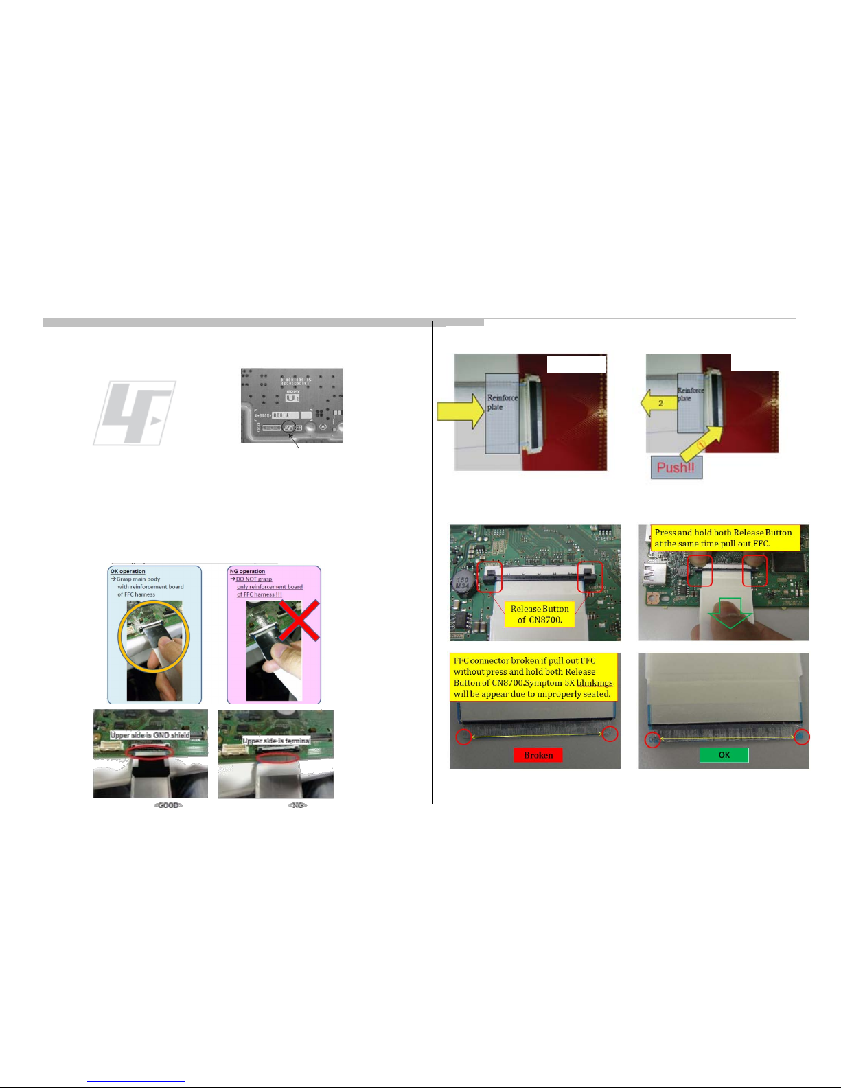
1-7. Lead Free Information
The circuit boards use d in these m odels have been processe d usi ng Lead
Free Solder. The boar ds are identi fied by the LF logo located cl ose to the
board designation.
Figure 4: LF Logo
Figure 5: LF logo on circuit board
The servicing of these boards requir es speci al precauti ons. I t is strongly
recommended t o use Lead Free Solder m aterial in order to guarantee optimal
quality of new solder j oints.
1-8. Handling the FLEXIBLE FLAT CABLE (FFC)
When you insert / pull out FFC, please grasp a reinforcement board and main
body of FFC.
< Insertion>
<Pull out>
Main Board
Main Board
Pleas e hold rein forc em en t boar d and
plunge it to depths.
Please pull out FFC while pushing the
butt on of bot h ends at the sam e time.
RB2G CHASSIS
W580B/W585B/W590B/W600B/W605B/W607B/W608B/WM15B
SECTION 2
SELF DIAGNOSTIC FUNCTION
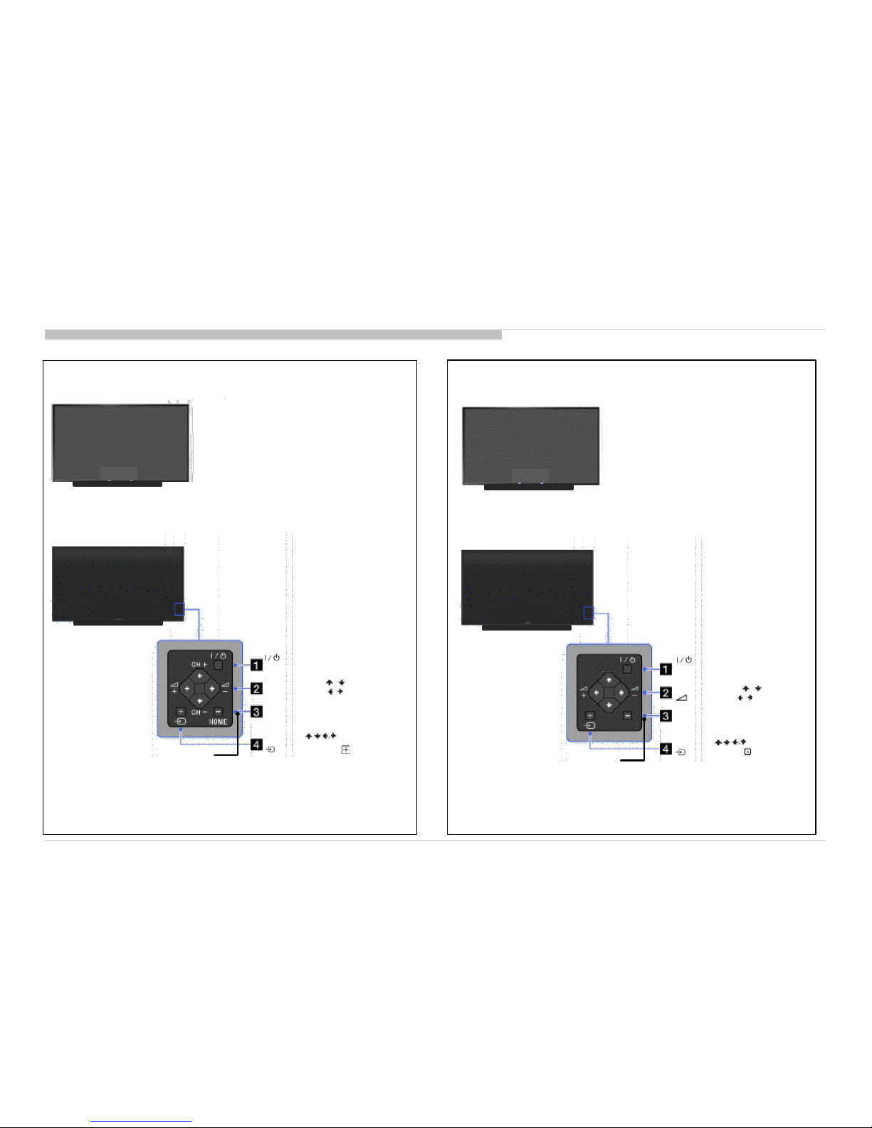
2-1. Overview o f Control Buttons
8
Self Diagnostic Function
2-1-1. (EXCEPT CHINA )
2-1-2. (CHINA)
频道 +
频道 -
主菜单
INPUT SELECT /
SELECT/ CONFIRM
Press to select the next or
previous channel.
In TV Home Menu: buttons
will work as (select/confirm)
+/- (Channel) / / ,
+/- (Volume) / / .
Press to select the next or
previous channel.
Press to adjust the volume.
In TV Home Menu: buttons
will work as , , , .
频道
Power
Turn the TV on or switch to standby mode
Press to display
the TV Home Menu.
主菜单
FRONT
REAR OF TV
HOME
Press to display
the TV Home Menu.
Power
Turn the TV on or switch to standby mode
INPUT SELECT /
SELECT/ CONFIRM
Press to select the next or
previous channel.
In TV Home Menu: buttons
will work as (select/confirm)
FRONT
CH+/- (Channel) / / ,
+/- (Volume) / / .
Press to select the next or
previous channel.
Press to adjust the volume.
In TV Home Menu: buttons
will work as , , , .
REAR OF TV
RB2G CHASSIS
W580B/W585B/W590B/W600B/W605B/W607B/W608B/WM15B
9
Self Diagnostic Function
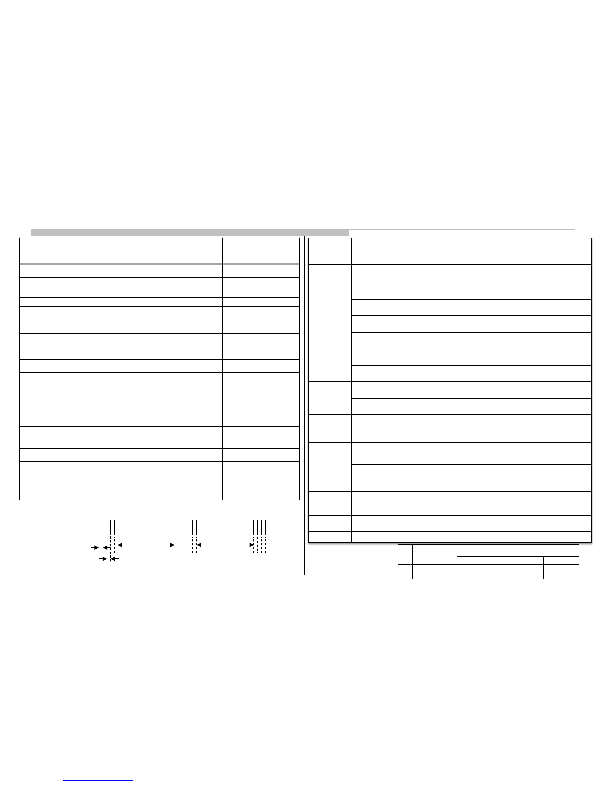
2-4. Standby LED Error Display
2-2. LED Display Control
Example: The figure above shows LED display when SHUTDOW N is caused by Audio
Error. It repeats flashing for a specified number of times in 0.5s ec/c ycl e and has a 3 seconds
interval of lighting off. Please note that a 3 seconds inter val of lighting off is f ixed regardless of abnormal state types.
When safety shutdown occurs, Standby LED display reports the cause by using the lightning
patterns as indicated below
.
2-3. LED Pattern
3.0sec 3.0sec
0.5sec
0.5sec
RED LED
blinking count
Detection Item s
Board Error Item
2x
Main 12V failure [MAIN_POWE]
* This failure is not saved
G** Board Error
BAX_L Board Error
3x
Main 5.0/3.3/1.8/1.0/ 1.1V failure [DC_ALERT]
* 5.0/1.0V failures are not saved.
BAX_L Board Error
Audio amp. protection [AUD_ERR]
BAX_L Board Error
Speaker
HDMI equa l i zer/switch I2C NACK [HDMI_EQ] * There is Temp.
sensor on the same I2C bus.
BAX_L Board Error
Tuner or demodulator I2C NACK [TU_DEMOD]
BAX_L Board Error
Tuner Board Error
AFE device I2C NACK [AFE_I2C]
BAX_L Board Error
Tuner Board Error
AFE device error SPI NACK [AFE_SPI] * only for AEP,CH
BAX_L Board Error
Tuner Board Error
4x
LED driver failure [LD_ERR]
LED Driver (LD) Board Error
Panel module
LED voltage error [VLED]]
LED Driver (LD) Board Error
Panel module
5x
Panel ID EEPROM I2C NACK (Also panel power failure is a
suspect) [P_ ID_ERR]
Panel module
Tcon board
G** Board Error
BAX_L Board Error
6x
Backlight failure [BACKLIGHT]
Panel module
G** Board Error
BAX_L Board Error
Backlight converter OVP [BACKLIGHT]
Panel module
Tcon board
G** Board Error
BAX_L Board Error
7x
Over temperature protection [TEMP_ERR]
Temp. sen so r I2C NACK [TEMP_ERR] * The r e is H DMI Eq on the
same I2C bus.
BAX_L Board Error
8x
Software Error (Also the main board’s memory or CAM module is a
suspect)
BAX_L Board Error
9x Tuner Board Error [TU_BOARD] Tuner Board Error
Size G** Board Type
Tun er B oar d
America/Pan Asia/Chin a/Eur ope Japan
40” Not applicable TUS TUW
48” Not applicable TUS TUW
Status
White Center
LED
(appl ic abl e for
HSC2 only)
Side RGB LED
Sid e Amber
LED
Remarks
Power O ff
( by power saving switch off and *1)
- Off Off
*1 power switch off (by side
key)
Power O n - G reen L it Off
STBY/i.LINK STBY/PC STBY
( by rem ot e c on t r ol off on l y )
- Off Off
Skyp e Cal l R ec ei v e - White one shot Off
Picture Off - White one shot Off
Devic e Con nec ti on - Cyan one shot Off
Power O N A n i mation - White one shot Off
Sleep Ti mer/ On
Tim er/ Rem i nd er/ RE C T im er /P h oto
Frame
( Power On )
-
Amber
Lit*2, *6
Off
*2 One Shot is only us er ac t ion .
*6 The act ual dat a behav i our is
“One S h ot -> Li t ” t o sol v e i s su e
relat ed to LED priori ty.
On Timer/Reminder/REC Timer
( Deep Standby )
- Off Amber
After 5 m i n ut es , s i de amber
LED On
Failure -
Red
Blinking
Off
The number of LED blinking
indi c ates cau se of fai l ur e
( refer to Led Error / Triage
chart)
Aging mode - Green Blinking Off Blinking:0.5sec On / 0.5sec Off
End of Aging mode - Green Blinking Off Blinking:3sec On / 3sec Off
Softw are U pdat ing - white blinking off
Software Updating finish - Blue lit off
Test R es et - white blinking
Amber
blinking
Error of panel I D - Green Blinking
Amber
Blinking
Blinking:0.5sec On / 0. 5sec O ff
REC (SCART REC & HDD
REC/LIVE PAUSE) [AEP/J on ly ]
-
Red(Pink)
Lit*2, *6
Off
*2 One Shot is only us er ac t ion .
*6 The act ual dat a behav i our is
“One S h ot -> Li t ” t o sol v e i s su e
relat ed to LED priori ty.
ePOP/
Shop Illumination
- Cyan loop Off
One sh ot Cen t er W h i t e when
featur e chang e.
RB2G CHASSIS
W580B/W585B/W590B/W600B/W605B/W607B/W608B/WM15B
2-5. Triage Ch art
Self Diagnostic Function
10
Secondary possible defective part
Most likely defective part
Size G** Board Type
TU Board
America/Pan Asia/Chin a/Eur ope Japan
40” Not applicable TUS TUW
48” Not applicable TUS TUW
Reference
Symptoms - Shutdown. Power LED
blinking red diagnostics sequences
No
Powe r
Video
- missing or distorted
Remote Network Audio Skype Smart Core
Bluetooth
(BT)
2 3 4 5 6 7 8 9 10
No White Power LED
& does not reponse
to remote (D ead S et)
Stationary
colored lines
or dots
No video On e
of Inputs
No video all
Inputs
No Remot e
Wireless
can't c onnect
No Audio
Skype
Can't Work
Smart Core no LED (Set
is still alive)
Bluetoo th / One
Step Remot e
(OSR) can't
connect
B* Board
p
l
p
p
l
l
p
p
l
l
p
p l p p p
TU board
p p
l
p
l
l
p
G* Board
l
p p
l
l
p
H* Board
l
l
Speaker
p
l
Skype Module
l
Camera Module
p
Mic. Module
l
Wifi Module
l
l
p
BT Module
l
LD* Board
l
p
LVDS FFC
p p
p p
Tcon
p l p
p p p
LCD Panel
l l l
p
l
p
Problem
Power Power LD
Panel
(Tcon)
Panel
(Backli ght) TEMP
Software Emitter
Audio
FAN
(N/A)
Local
I2C
RB2G CHASSIS
W580B/W585B/W590B/W600B/W605B/W607B/W608B/WM15B
11
SECTION 3
TROUBLESHOOTING
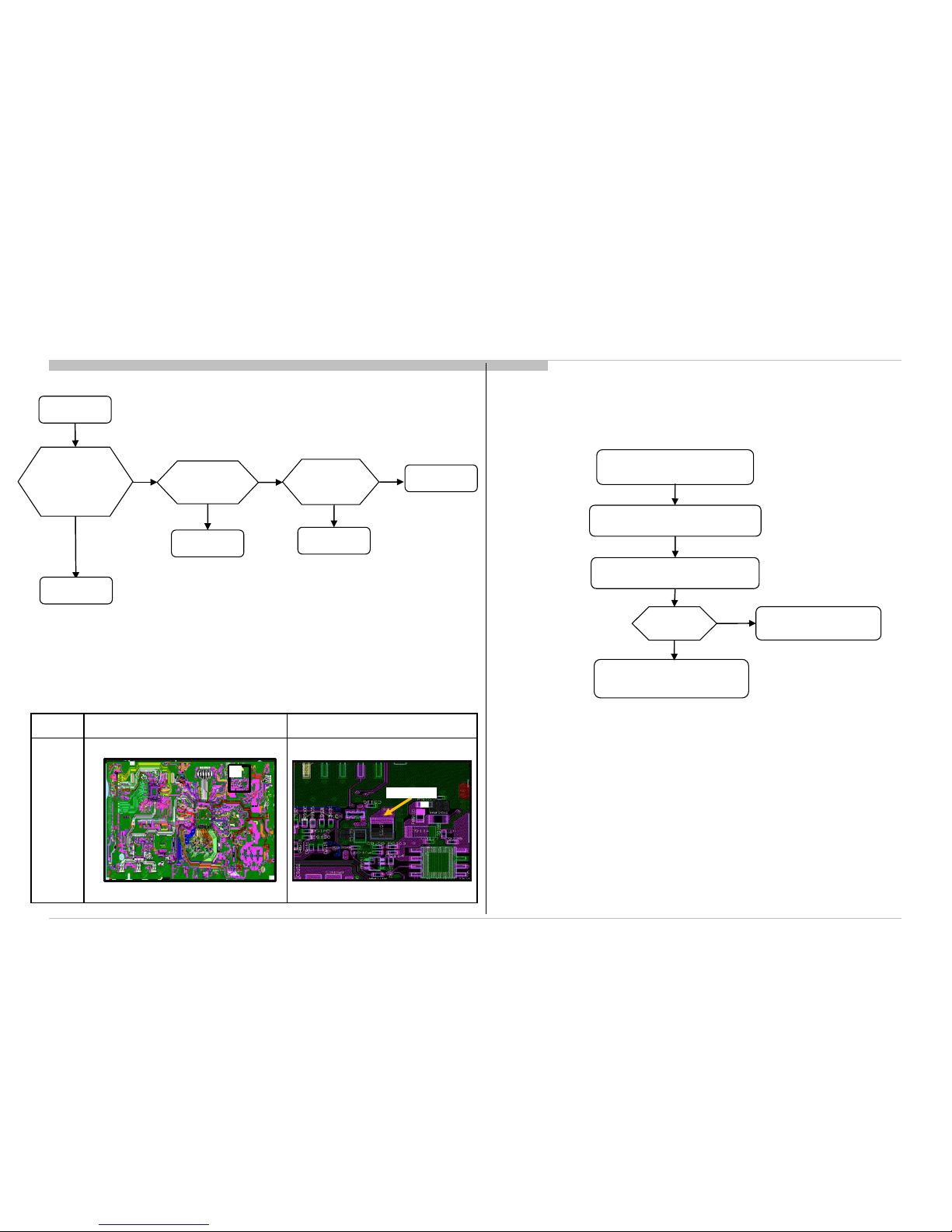
3-1. NO POWER
Parts Board PWB (BAXL- A si d e ) Detail
(L9107)
Troubleshooting
No Power
Check STBY 3.3V
L9107
Harness
Adapter
Replace
Between LD Board to
B* Board Harness
BAXL Board
NG
OK
NG
OK
Replace
LD- Board
NG
LD Board
OK
For HT, HM, change LD board.
For HE, change Panel.
3-1-1. NO POWER AC ADAPTER
1
L9107
Note :
-B* Board – BAXL Board
3-1-2. NO POWER – AYU2/AY U 2L fail ur e
AYU2/L Fail Suspected
Replace BAXL Board
No
eMMC / RawNAND erase
Product SW rewrite
Recover?
Product SW
writing issue
Yes
RB2G CHASSIS
W580B/W585B/W590B/W600B/W605B/W607B/W608B/WM15B
12
Troubleshooting
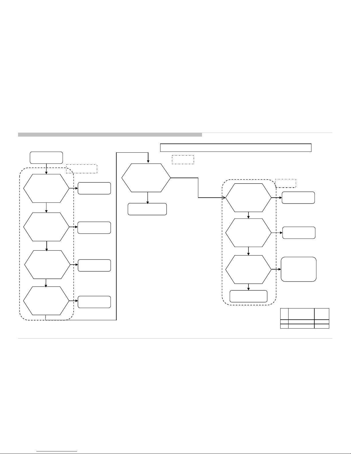
3-2-1. LED Bli nking: 3x (D C Alert & Communication Err or)
3-2. LED BLINKING
Size G** Board Type B* Board
40” Not applicable BAX_L
48” Not applicable BAX_L
Speaker
Check
Speaker Impedance
at SP Connector
Check
Audio +12.5V
at pin 18/20 of CN9101
on the B* Board
(except Adapter model)
G* Board
Check
+12.5V / +19.5V
at Power Amp side
of F4401 / F4601 on
the B* Board
F4401 / F4601,
IC4901 / IC4601
,etc
(B* Board)
IC4901 / IC4601,etc
(B* Board)
AUDIO
NG
OK
NG
OK
NG
OK
TUNER Board
TUNER
NG
3-time blinking
Check D+1.0V at
JL9003 / JL9127 on
the B* Board
F9105,IC9103,
Etc (B* Board)
Check
+3.3V_MAIN_1
at JL9117 on
the B* Board
F9104,IC9104,
etc (B* Board)
DC_ALERT
NG
OK
NG
OK
NG
Check
+1.8V_MAIN on
Pin 2 of IC9201
IC9201,etc
(B* Board)
Check
+5.0V_MAIN
at JL9113 / JL9112 on
the B* Board
NG
OK
IC9102 / IC9101
,etc (B* Board)
OK
Note: For location details, refer to troubleshooting Reference for parts location.
Change TUS/TUW
Board
RB2G CHASSIS
W580B/W585B/W590B/W600B/W605B/W607B/W608B/WM15B
13
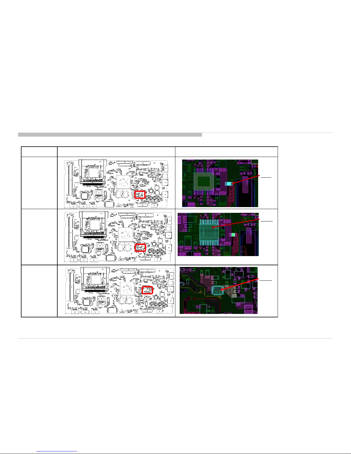
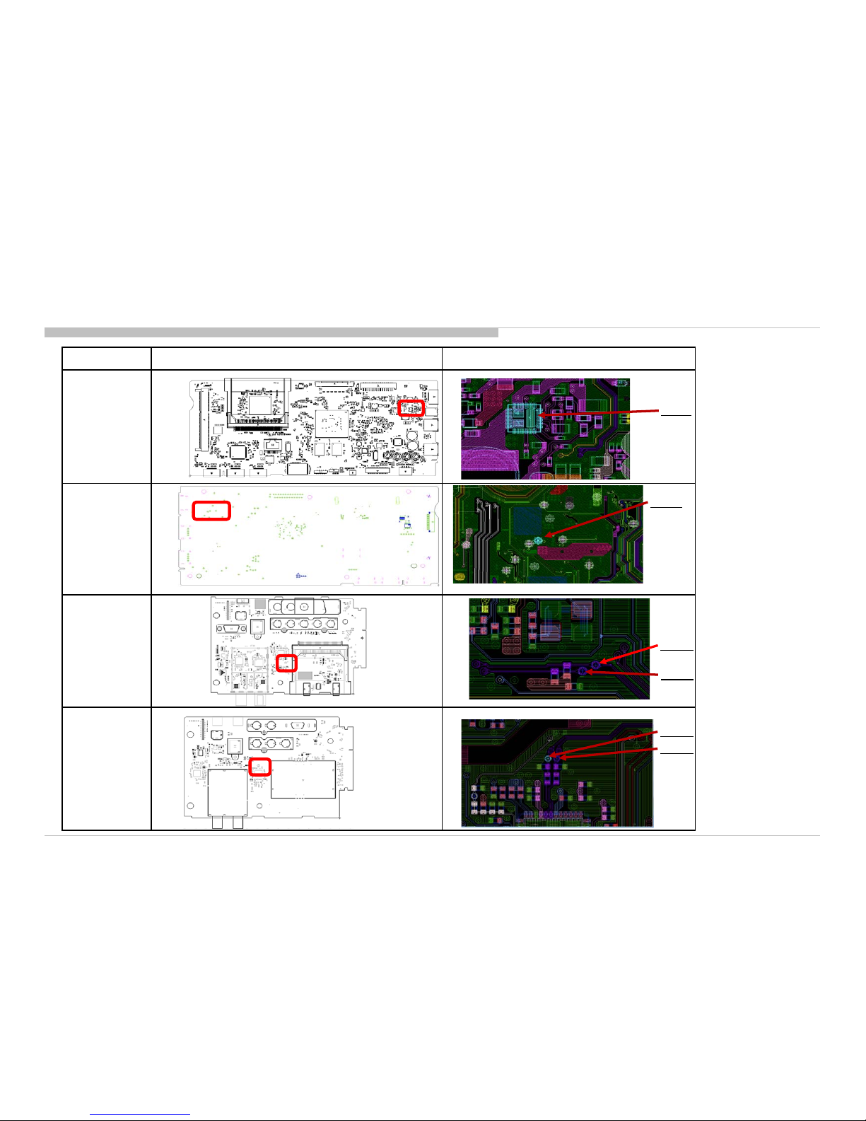
Troubleshooting
Board / Parts Board PWB (A side) Detail
BAXL
(F9104)
BAXL
(IC9104)
BAXL
(IC9201)
F9104
IC9104
IC9201
3-2-1. LED Blinking: 3x (DC Alert & Communication Error)
Troubleshooting References (a)
RB2G CHASSIS
W580B/W585B/W590B/W600B/W605B/W607B/W608B/WM15B
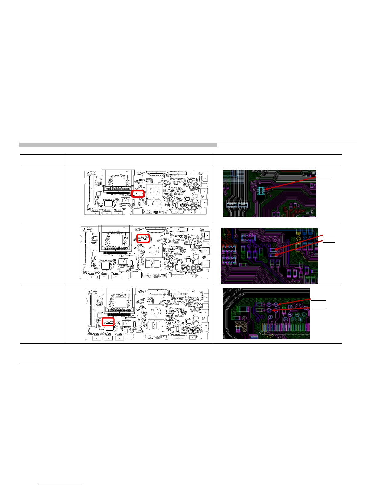
Board / Parts Board PWB (A side) (B side) Detail
BAXL
(IC9101)
BAXL
(JL9112)
TU-S (Others)
(CL2101,
CL2102)
TU-W (Japan)
(CL2318,
CL2319)
14
Troubleshooting
IC9101
JL9112
B-Side
CL2318
CL2319
CL2102
CL2101
3-2-1. LED Bli nking: 3x (D C Alert & Communication Err or)
Troubleshooting References (b)
RB2G CHASSIS
W580B/W585B/W590B/W600B/W605B/W607B/W608B/WM15B
Board /Parts Board PWB (A side) Detail
BAXL
(RB8517)
BAXL
(R8546, R8547)
BAXL
(CL5023, CL5024)
15
Troubleshooting
B-Side
RB8517
R8546
R8547
CL5023
CL5024
3-2-1. LED Bli nking: 3x (D C Alert & Communication Err or)
Troubleshooting References (c)
 Loading...