

Sony KDL-40XBR6, KDL-46XBR6, KDL-52XBR6 Operating Instruction

4-113-760-11(1)
LCD Digital Color TV
Operating Instructions
KDL-40XBR6
KDL-46XBR6
KDL-52XBR6
© 2008 Sony Corporation

Owner’s Record
The model and serial numbers are located
at the rear of the TV. Record these
numbers in the spaces provided below.
Refer to them whenever you call upon
your Sony dealer regarding this TV.
Model Name
Serial No.
CAUTION
To prevent electric shock and blade exposure,
do not use this polarized AC plug with an
extension cord, receptacle or other outlet
unless the blades can be fully inserted.
s Operate the TV only on 120 V AC.
Declaration of Conformity
Trade Name: SONY
Model: KDL-40XBR6/KDL-46XBR6/
KDL-52XBR6
Responsible Party: Sony Electronics Inc.
Address: 16530 Via Esprillo,
San Diego, CA 92127 U.S.A.
Telephone Number: 858-942-2230
This device complies with part 15 of the
FCC rules. Operation is subject to the
following two conditions: (1) This device
may not cause harmful interference, and (2)
this device must accept any interference
received, including interference that may
cause undesired operation.
NOTIFICATION
This equipment has been tested and found to
comply with the limits for a Class B digital
device, pursuant to Part 15 of the FCC Rules.
These limits are designed to provide
reasonable protection against harmful
interference in a residential installation. This
equipment generates, uses and can radiate
radio frequency energy and, if not installed and
used in accordance with the instructions, may
cause harmful interference to radio
communications.
However, there is no guarantee that
interference will not occur in a particular
installation. If this equipment does cause
harmful interference to radio or television
reception, which can be determined by turning
the equipment off and on, the user is
encouraged to try to correct the interference by
one or more of the following measures:
s Reorient or relocate the receiving antenna.
s Increase the separation between the
equipment and receiver.
s Connect the equipment into an outlet on a
circuit different from that to which the
receiver is connected.
s Consult the dealer or an experienced radio/
TV technician for help.
Pursuant to FCC regulations, you are
cautioned that any changes or modifications
not expressly approved in this manual could
void your authority to operate this
equipment.
For Customers in Canada
This Class B digital apparatus complies with
Canadian ICES-003.
CAUTION
Use the following Sony TVs only with the
following WALL-MOUNT BRACKET or
TV-stand.
Sony TV Model No.
KDL-
40XBR6
Sony
Wall-Mount
Bracket
Model No.
Sony TV
Stand
Model No.
Use with other WALL-MOUNT BRACKETS
or TV stands may cause instability and
possibly result in injury.
To Customers
Sufficient expertise is required for installing
the specified TV. Be sure to subcontract the
installation to a Sony dealer or licensed
contractor and pay adequate attention to safety
during the installation.
Note
This television includes a QAM demodulator
which should allow you to receive
unscrambled digital cable television
programming via subscription service to a
cable service provider. Availability of digital
cable television programming in your area
depends on the type of programming and signal
provided by your cable service provider.
Licensing Information
Macintosh is a trademark of Apple Inc.,
registered in the U.S. and other countries.
HDMI, the HDMI logo and High-Definition
Multimedia Interface are trademarks or
registered trademarks of HDMI Licensing,
LLC.
Fergason Patent Properties, LLC:
U.S. Patent No. 5,717,422
U.S. Patent No. 6,816,141
Manufactured under license from Dolby
Laboratories. Dolby and the double-D symbol
are trademarks of Dolby Laboratories.
In the United States, TV Guide and other
related marks are registered marks of
Gemstar-TV Guide International, Inc. and/or
one of its affiliates. In Canada, TV Guide is a
registered mark of Transcontinental Inc., and is
used under license by Gemstar-TV Guide
International, Inc.
The TV Guide On Screen system is
manufactured under license from Gemstar-TV
Guide International, Inc. and/or one of its
affiliates.
The TV Guide On Screen system is protected
by one or more of the following United States
patents 4,908,713; 6,498,895; 6,850,693;
6,396,546; 5,940,073; 6,239,794 to
Gemstar-TV Guide International, Inc. and/or
its subsidiaries.
Gemstar-TV Guide International Inc. and/ or its
related affiliates are not in any way liable for
the accuracy or availability of the program
schedule information or other data in the TV
Guide On Screen system and cannot guarantee
service availability in your area. In no event
shall Gemstar-TV Guide International, Inc.
and/or its related affiliates be liable for any
damages in connection with the accuracy or
availability of the program schedule
information or other data in the TV Guide On
Screen system.
KDL-
46XBR6
SU-WL500
WS-S10LS
SU-FL71M –
KDL-
52XBR6
Blu-ray Disc is a trademark.
“BRAVIA” and , S-Force,
Motionflow, BRAVIA Sync, , DMe
MICRO VAULT, and “x.v. Color” are
trademarks or registered marks of Sony
Corporation.
“XrossMediaBar” is a trademark of Sony
Corporation. “XMB” is a trademark of Sony
Corporation and Sony Computer
Entertainment Inc.
“PLAYSTATION” is a registered trademark
and “PS3” is a trademark of Sony Computer
Entertainment Inc.
Adobe is a registered trademark or a trademark
of Adobe Systems Incorporated in United
States and/or other countries.
®
, the DLNA Logo and DLNA
DLNA
CERTIFIED™ are trademarks, service marks,
or certification marks of the Digital Living
Network Alliance.
x
,
For Customers in the United
States
Lamp in this product contains
mercury. Disposal of these
materials may be regulated due
to environmental considerations.
For disposal or recycling
information, please contact your
local authorities or the
Electronic Industries Alliance
(www.eiae.org).
2
Contents
Welcome to the World of BRAVIA®
The Four Steps to a Full HD Experience: Set,
Sound, Source, and Setup............................4
Picture Quality and Aspect Ratio.......................4
TV Home Menu: XMB
(XrossMediaBar)..........5
™
Getting Started
1. Installing the TV...............................................6
Carrying the TV ..............................................6
Preparation for Table-Top Stand....................6
Preparation for Wall-Mount Bracket ...............7
When Installing the TV Against a Wall or
Enclosed Area.............................................7
Bundling the Connecting Cables ....................8
Securing the TV..............................................9
2. Locating Inputs and Outputs .......................10
3. Connecting the TV.........................................12
Cable System or VHF/UHF Antenna
System ......................................................12
Cable System and VHF/UHF Antenna
System ......................................................12
HD Cable Box/HD Satellite Box....................12
PC.................................................................14
Other Equipment ..........................................15
4. Setting Up the Channel List –
Initial Setup ..................................................16
Operating the TV
Inserting Batteries into the Remote Control...18
When Using the Remote Control .....................18
TV Controls........................................................18
Remote Control Button Description................19
Indicators ...........................................................24
Programming the Remote Control...................25
Programming Other Equipment....................25
Auto Backlight...............................................25
Backlight Time Out .......................................25
Reset the Remote Control............................25
Manufacturer’s Code List .................................26
Sony Equipment Codes................................26
Other Manufacturer Equipment Codes.........26
Using Other Equipment with Your Remote
Control..........................................................27
Exploring Fun Features
Favorites ............................................................28
Displaying Favorites.....................................28
Navigating Favorites.....................................28
Adding to Favorites.......................................28
Removing from Favorites .............................28
Quick Setup Guide (separate volume)
Provides a variety of optional equipment
connection diagrams.
Background TV..................................................29
Navigating Background TV...........................29
DLNA Certified™ Photo Media Player.............29
Enjoying Photos and Music through
USB Port.......................................................29
Using USB Equipment..................................29
Removing USB Equipment...........................29
USB Equipment Functionality.......................29
Photo ..................................................................30
Accessing Photos.........................................30
Navigating through Photo.............................30
Photo Options...............................................31
Music ..................................................................32
Accessing Music...........................................32
Navigating through Music.............................33
Music Options...............................................33
How to Use TV Guide On Screen.....................34
Using BRAVIA Sync with Control for HDMI....36
Using DIGITAL MEDIA PORT Adapter.............36
Using P&P and PIP Features............................37
To Enter P&P and PIP..................................37
To Change Inputs or Channels ....................37
To Exit from P&P and PIP............................37
Using TV Settings
Media Category Icons.......................................38
Navigating through TV Home Menu
TV Settings Descriptions..................................40
Adjusting TV Settings .............................38
Viewing Photos.......................................38
Listening to Music...................................38
Watching TV ...........................................38
Accessing External Inputs ......................38
on XMB
CC
......................................................39
™
Product Support......................................40
Clock/Timers Settings.............................40
Picture Settings ......................................41
Sound Settings .......................................43
Screen Settings ......................................44
Channel Settings ....................................46
Closed Captions (CC) Settings...............47
Parental Lock Settings............................47
External Inputs Settings..........................50
HDMI Settings ........................................50
Network Settings ....................................51
General Setup Settings ..........................51
Initial Setup.............................................52
Other Information
Troubleshooting................................................53
Specifications....................................................57
Index...................................................................58
Customer Support
United States
http://www.sony.com/tvsupport
Canada
http://www.sony.ca/support
On-line Registration
United States
http://productregistration.sony.com
Canada
http://www.sonystyle.ca/registration
3
Welcome to the World of BRAVIA
o
Thank you for purchasing this Sony BRAVIA® high-definition television. The quality of the image you
see on your
stunning detail of your new
can receive and display HD programming from:
• Over-the-air broadcasting via HD-quality antenna
• HD cable subscription
• HD satellite subscription
• Blu-ray Disc™ player or other HD compatible external equipment
Contact your cable or satellite provider for information on upgrading to HD programming.
BRAVIA
TV is only as good as the quality of the signal it receives. To experience the
BRAVIA
TV, you need access to HD programming. Your
®
BRAVIA
To learn more about HDTV, visit:
U.S.A. http://www.sony.com/HDTV
Canada http://www.sonystyle.ca/hd
The Four Steps to a Full HD Experience: Set, Sound, Source, and Setup
Along with your BRAVIA TV set, a complete HD system requires an HD sound system, a
source of HD programming and proper setup connections. This manual explains basic setup
connections (see page 12). The Quick Setup Guide, enclosed separately, illustrates how to
connect other optional equipment.
TV
Picture Quality and Aspect Ratio
You can enjoy crisp, clear images, smooth movement and high-impact visuals from 1080 HD
signals. When you compare a high-definition signal to a standard analog signal, you will notice
a big difference.
High-definition and standard-definition signals are transmitted with different aspect ratios (the
width-to-height ratio of the image). HDTV uses a wider screen than conventional standarddefinition TV.
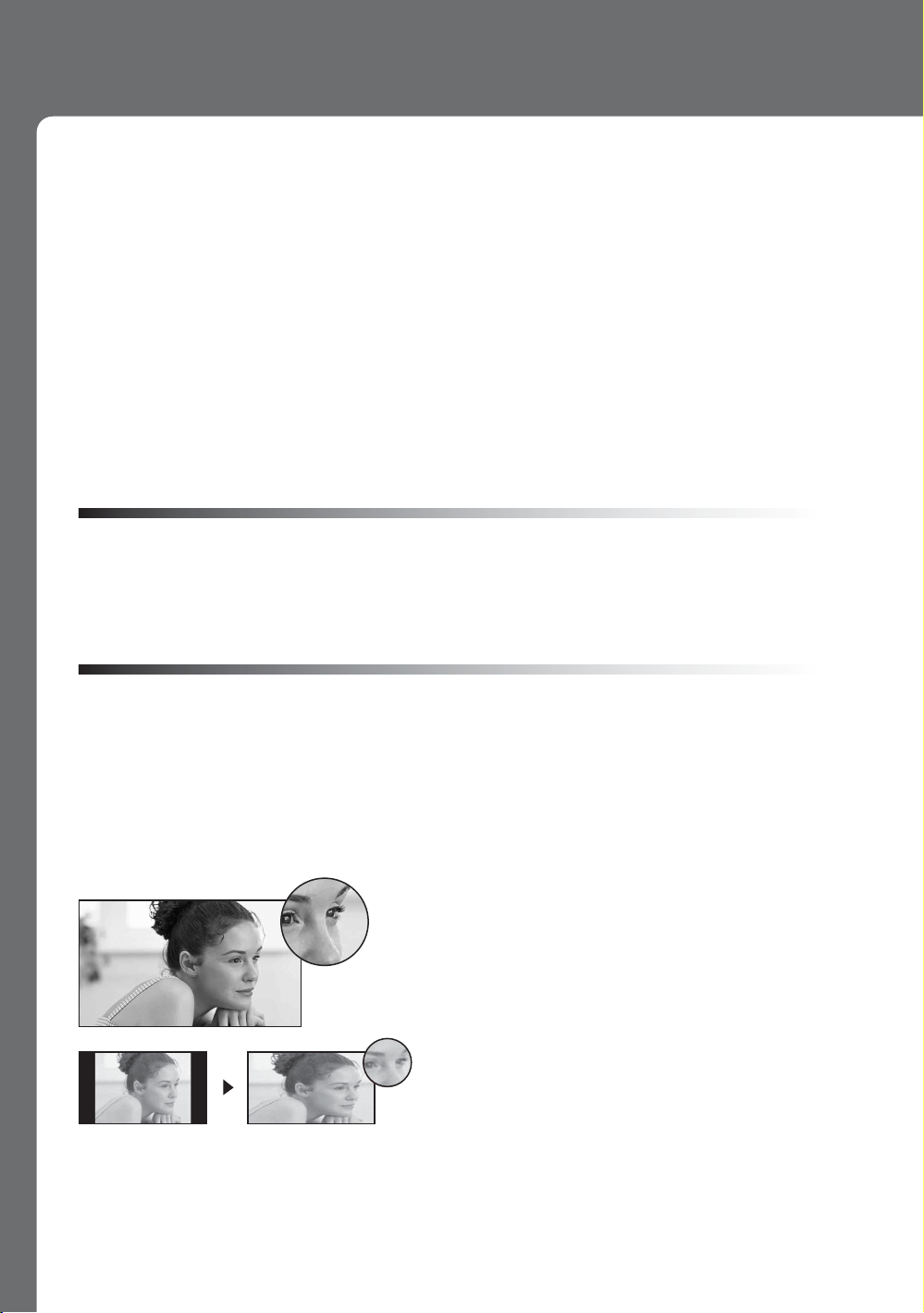
16:9 (high-definition) source
Most HDTV signals use a wide screen aspect rati
of 16:9. The 16:9 fills your BRAVIA screen,
maintaining a crisp, clear, vivid picture.
4:3 (standard-definition) source
Most standard-definition signals use a boxy 4:3
aspect ratio. When a 4:3 image is displayed on an
HDTV, you will see black bars on the sides. The
picture quality may not be as sharp as with HD
sources.
~
• You can use the Wide Mode function of the TV to adjust the 4:3 image to fit the entire screen (see pages 21, 44
and 45).
4
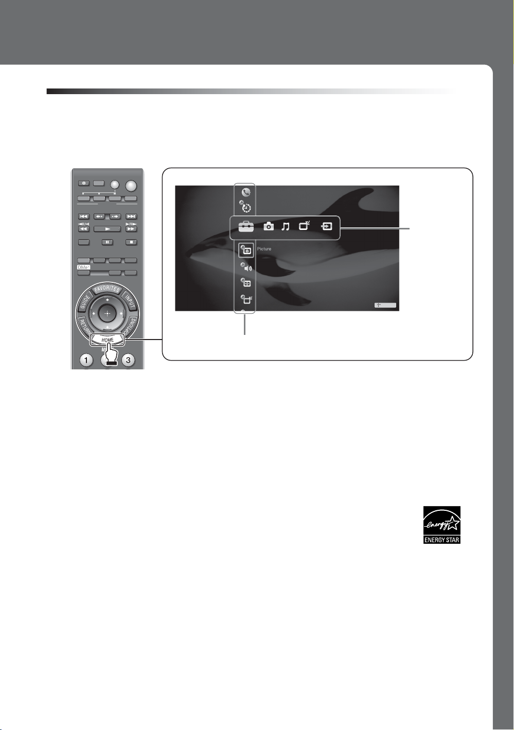
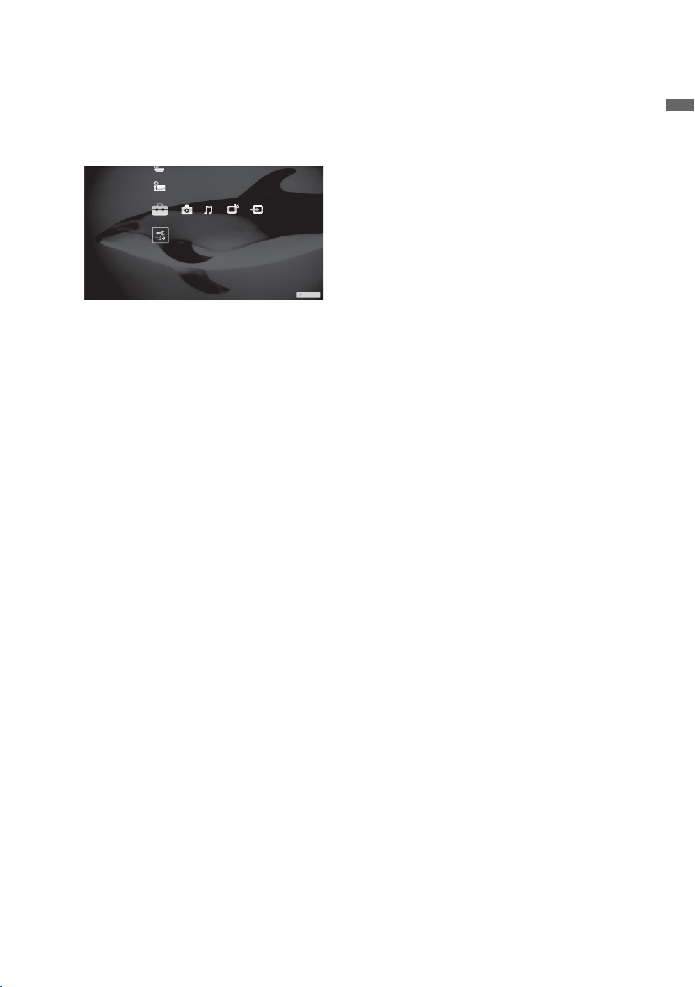
TV Home Menu: XMB™ (XrossMediaBar)
The XMB™ is an easy way to access the TV settings for customizing, making adjustments,
viewing the available TV channels, photo and music files, and selecting connected equipment.
Press the HOME button on your remote control to display the XMB
DISPLAY
LIGHT POWER
TV POWER
DVD AMP STB TV
FUNCTION
PREV REPLAY ADVANCE NEXT
PLAY
SYNC MENU PAUSE
THEATER SOUND PICTURE WIDE
CC FREEZE
STOP
Product Support
Clock/Timers
Settings
Sound
Screen
Channel
Category Object Bar
From the horizontal Media Category Bar you can control:
• Settings: adjust timer, picture, sound, screen and other options (see page 40 for
customization options).
• Photo: view photo files via USB or compatible DLNA Certified™ equipment (see page
30).
• Music: listen to music files via USB or add music to a slideshow (see page 32).
• TV Channels: access TV Guide On Screen™ and available channels.
• External Inputs: select cable, satellite, VCR, DVD players or other optional equipment
can also be selected from the vertical Category Object Bar from the External Inputs.
.
™
Media
Category
Bar
TV
Your BRAVIA TV is Energy Star Compliant. It meets strict energy efficiency
guidelines set by the EPA and US Department of Energy. ENERGY STAR is a
joint program of these government agencies, designed to promote energy
efficient products and practices.
• When the TV is initially set up, it is designed to stay within the Energy Star guidelines.
• Changes to certain features, settings, and functionalities of this TV (i.e. TV guide, Picture/
Sound, Light Sensor, Power Savings) can slightly change the power consumption.
Depending upon such changed settings, the power consumption may increase which
possibly could exceed the limits required for the Energy Star qualification.
~
•
This manual is for the 40, 46 and 52 inch
BRAVIA
KDL-XBR6 series models with screen size measured diagonally.
5
Getting Started
1. Installing the TV
This TV can be mounted on a wall using a WallMount Bracket or placed on a TV stand (each sold
separately). This section will explain:
• How to carry the TV
• Preparation for a Table-Top stand
• Preparation for a Wall-Mount Bracket
• Installation against a wall or enclosed area
• Bundling the connecting cables
• Securing the TV
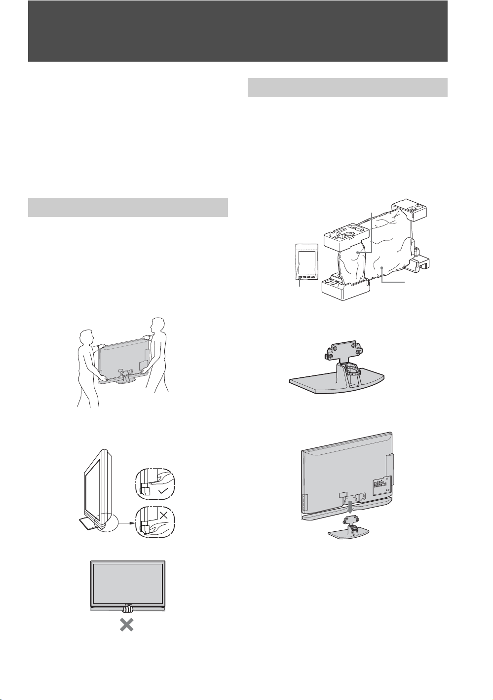
Carrying the TV
Be sure to follow these guidelines to protect your
property and avoid causing serious injury.
• Before carrying the TV, disconnect all cables.
• Carrying the large size TV requires two or more
people.
• When carrying the TV, place your hand as
illustrated and hold it securely. Do not subject the
TV to shocks, vibration, or excessive force.
Preparation for Table-Top Stand
Follow the assembling steps required to place on a
TV stand (except model, KDL-52XBR6).
1 Remove the Table-Top Stand and screws from
the carton. The screws can be found in the
accessory bag.
For product protection and safety reasons,
Sony strongly recommends that you use the
screws provided with the TV.
Table-Top Stand
TV Unit
Screws
2 Place the Table-Top Stand on a level and
stable surface.
• Lift the TV by placing your palm directly
underneath the panel but do not put stress on the
LCD panel.
• Do not lift the TV from the bottom center.
6
3 Gently slide the TV unit onto the neck of the
Table-Top Stand and align the screw holes.
~
• Do not put stress on the LCD panel or the frame
around the screen.
• Be careful to not pinch your hands or the AC power
cord when you install the TV unit to the Table-Top
Stand.
4 Use the supplied screws to attach the TV unit
to the Table-Top Stand (refer to the “Attaching
the Table-Top Stand” flyer).
If an electric
AC IN
Preparation for Wall-Mount Bracket
All models are ready to be mounted on a wall.
screwdriver is used, set
the torque to tighten at
approximately 1.5 N·m,
15 Kgf·cm.
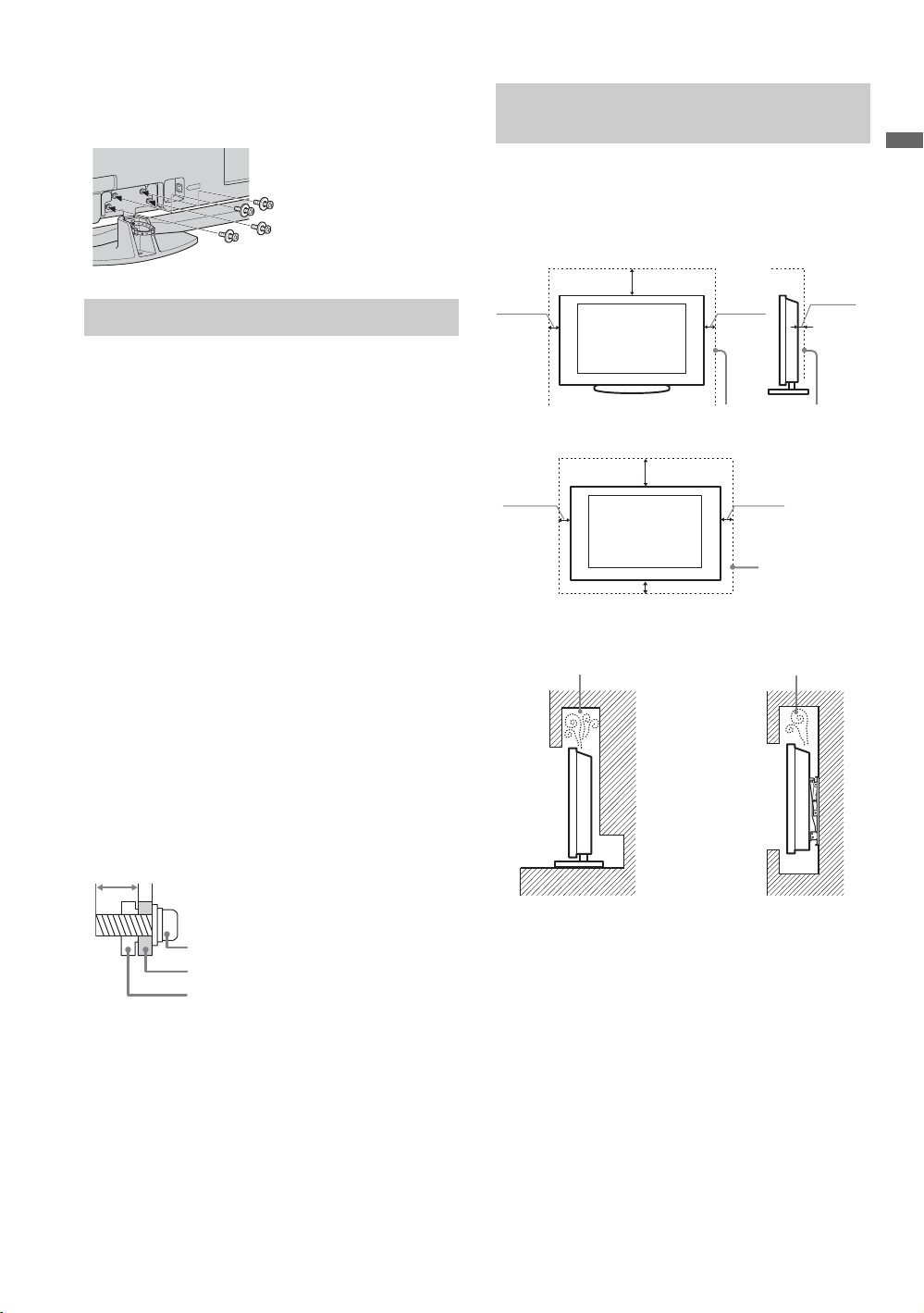
When Installing the TV Against a Wall or Enclosed Area
Make sure that your TV has adequate air
circulation. Allow enough space around the TV as
shown below. Avoid operating the TV at
temperatures below 41 °F (5 °C).
Installed with stand
4 inches
(10 cm)
11
(30 cm)
7
/
inches
8
4 inches
(10 cm)
3
inches
/
2
8
(6 cm)
Getting Started
• For product protection and safety reasons,
Sony strongly recommends that you use the
Wall-Mount Bracket model designed for your
TV and the wall-mounting of your TV should
be performed by a Sony dealer or licensed
contractor.
• Sufficient expertise is required in installing this
TV, especially to determine the strength of the
wall for withstanding the TV’s weight.
• Be sure to use the screws supplied with the WallMount Bracket when attaching the mounting
hooks to the TV set.
The supplied M6 screws are designed so that they
are 8 mm to 12 mm in length when measured
from the attaching surface of the mounting hook.
The diameter and length of the screws differ
depending on the Wall-Mount Bracket model.
Use of screws other than those supplied may
result in internal damage to the TV set or cause it
to fall, etc.
8-12 mm
M6 screw (supplied with the Wall-Mount
Bracket)
Mounting Hook
Rear of the TV set
• Be sure to store the unused screws and Table-Top
Stand in a safe place until you are ready to attach
the Table-Top Stand. Keep the screws away from
small children.
For details on how to use the Wall-Mount Bracket
compatible with your model, visit
www.sony.com/accessories
Or call 1-800-488-7669 (for United States)
1-877-899-7669 (for Canada)
Leave at least this much space around the set.
Installed on the wall
7
11
inches
/
8
(30 cm)
4 inches
(10 cm)
4 inches (10 cm)
4 inches
(10 cm)
Leave at least
this much space
around the set.
Never install the TV set as follows:
Air circulation is blocked.
Wall
Air circulation is blocked.
Wall
~
• Inadequate air circulation can lead to overheating of
the TV and may cause damage to your TV or cause a
fire.
Consider the following for best picture
quality
• Do not expose the screen to direct illumination
or sunlight.
• Use spot lighting directed down from the
ceiling or cover the windows that face the
screen with opaque drapery.
• Install the TV in a room where the floor and
walls are not of a reflective material.
(Continued)
7

• When moving the TV from a cold area to a
warm area, a sudden room temperature change
may cause the TV’s picture to blur or show
poor color due to moisture condensation.
Should this occur, please wait a few hours to
allow the moisture to evaporate before
powering on the TV.
Bundling the Connecting Cables
You can bundle the connecting cables as illustrated
below.
IN
C
A
~
• Do not bundle the AC
power cord with other
connecting cables.
8
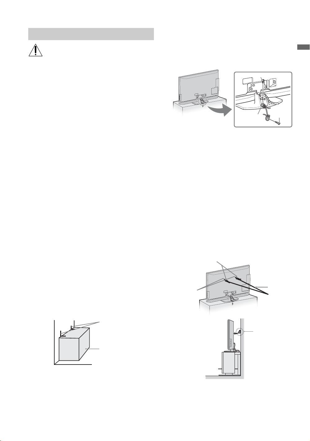
Securing the TV
Sony strongly recommends taking
measures to prevent the TV from toppling
over. Unsecured TVs may topple and
result in property damage, serious bodily
injury or even death.
Prevent the TV from Toppling Over
s Secure the TV to a wall and/or stand.
s Do not allow children to play or climb on
furniture and TV sets.
s Avoid placing or hanging items on the TV.
s Never install the TV on:
• slippery, unstable and/or uneven surfaces.
• furniture that can easily be used as steps,
such as a chest of drawers.
s Install the TV where it cannot be pulled,
pushed, or knocked over.
s Route all AC power cords and connecting
cables so that they are not accessible to
curious children.
Use a Sony TV Stand
Use a Sony specified TV stand (see page 2) and
follow the instruction manual provided with the
Sony TV stand.
If a Sony specified TV stand is not used, consider
the following recommended measures.
Recommended Measures to Secure the TV
Secure the Stand for the TV
Make sure the TV stand can adequately support
the weight of the TV. Use two angle braces (not
supplied) to secure the stand.
For each angle brace use the appropriate hardware
to:
• attach one side of the angle brace to the wall stud.
• attach the other side to the TV stand.
Angle brace
Stand
• Rope or chain (strong enough to support the
weight of the TV). Make sure that there is no
excess slack in the rope or chain.
An alternative way to secure the TV is with an
optional Sony Support Belt Kit.
Anchor bolt
Screw hole
on the TableTop Stand
Screw
~
Contact Sony Customer Support to purchase the optional
Support Belt Kit by providing your TV model name.
• For United States call: 1-800-488-7669 or visit:
www.sony.com/accessories
• For Canada call: 1-877-899-7669
Anchor the TV to the Wall
Use the hardware listed below (not supplied):
•Two M6 × 10-12 mm anchor bolts (screw into
the top-most wall-mount holes located on the
rear of the TV)
• Rope or chain (attach to one M6 anchor bolt)
• Wall-anchor (attach to the wall stud) strong
enough to support the weight of the TV (pass
the rope through the wall-anchor, then attach
to the other M6 anchor bolt)
Anchor bolts
Wall-mount
holes
Rope or
chain
Wallanchor
Getting Started
Secure the TV to the Stand
Use the optional hardware listed below (not
supplied):
•M6 × 10-12 mm anchor bolt (screwed into the
TV’s Table-Top Stand)
• A screw or similar (attach it to the TV stand)
~
• Securing the TV to the stand without securing it and
the stand to the wall provides minimum protection
against the TV toppling over. For further protection,
follow all three measures recommended above.
9
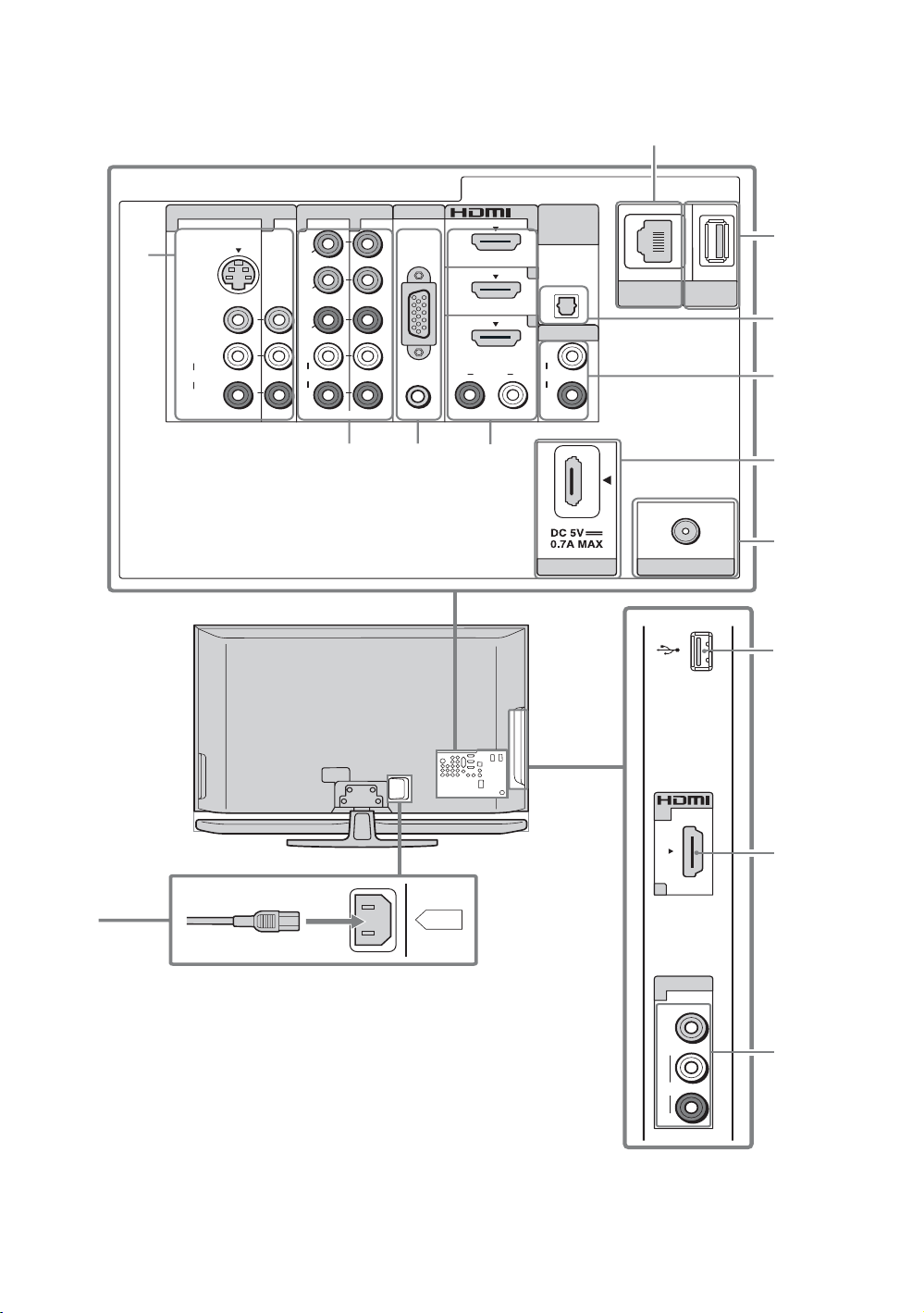
2. Locating Inputs and Outputs
Rear of TV
1
5
VIDEO IN
1 3 1
S VIDEO
VIDEO
L
(MONO)
A UDIO
R
COMPONENT IN
1
Y
B
P
R
P
L
AU DI O
R
(1080p/1080i/720p/480p/480i )
2
PC IN
2
RGB
AU DI O R L
3
4
IN
3
4
AU DIO OU T
AU DI O AU DI O
DIGITAL
AUDIO
OUT
(OPTICAL)
L
R
(V AR/FIX)
DMPOR T
LAN
(10/100)
CABLE/ANTENNA
x
DMe /
SER VICE
6
7
8
9
0
Side Panel
qa
qs
AC IN
~
• This TV displays all video input signals in a resolution of 1,920 dots × 1,080 lines.
• An HDMI or Component video (YP
BPR) connection is required to view 480i, 480p, 720p, 1080i and 1080p video
formats. 1080/24p is available only with HDMI connection.
10
IN
2
VIDEO IN
2
VIDEO
(MONO)
L
AU DI O
R
4
1
Item Description
1 VIDEO IN 1
S VIDEO
VIDEO IN 2/3
VIDEO/L(MONO)AUDIO-R
2 COMPONENT IN
1/2 (1080p/1080i/
720p/480p/480i)/
L-AUDIO-R
3 PC IN
(RGB/AUDIO)
Connects to the S VIDEO output jack of video equipment. If both composite video and
S VIDEO are connected, S VIDEO signal has priority.
Connects to the composite video and audio output jacks on your A/V equipment.
~
• If you have mono equipment, connect its audio output jack to the TV’s L (MONO)
audio input jack.
Connects to your equipment’s component video (YP
Connects to a personal computer’s video and audio output connector (see page 14). Can
also be connected to other analog RGB equipment. See “PC Input Signal Reference
Chart” on page 14 for the signals that can be displayed.
~
• For some Apple Macintosh computers, it may be necessary to use an adapter (not
supplied). If this is the case, connect the adapter to the computer before connecting the
HD15-HD15 cable.
• If the picture is noisy, flickering or not clear, adjust Phase and Pitch of Screen
settings on page 45.
4 HDMI IN 1/2/3
HDMI (High-Definition Multimedia Interface) provides an uncompressed, all-digital
audio/video interface between this TV and any HDMI-equipped A/V equipment. HDMI
supports enhanced, or high-definition video, plus digital audio.
Getting Started
BPR) and audio (L/R) jacks.
HDMI IN 4
R-AUDIO-L
If the equipment has a DVI jack and not an HDMI jack, connect the DVI jack to the
HDMI IN 4 (with DVI-to-HDMI cable or adapter) jack, and connect the audio jack to the
AUDIO IN (L/R) jacks of HDMI IN 4.
~
• Be sure to use only an HDMI cable that bears the HDMI logo.
• When connecting a DVI-equipped PC to an HDMI jack, also connect an Audio cable
between the PC and R-AUDIO-L jack.
5 LAN (10/100) Connects to a Local Area Network using an Ethernet cable. You can use this connection
x
6 DMe
7 DIGITAL AUDIO
8 AUDIO OUT
9 DMPORT Connects to devices via a DIGITAL MEDIA PORT interface (not supplied) and displays
0 CABLE/
qa USB Connects to USB equipment to access photo files and music files (see page 29).
qs AC IN Connects to your power source. Connect the supplied power cord to AC IN and the
* Manufactured under license from Dolby Laboratories. “Dolby” and the double-D symbol are trademarks of Dolby Laboratories.
/
SERVICE
OUT (OPTICAL)
(VAR/FIX)
ANTENNA
to connect to a network, receive software updates and enjoy photos from the Internet (see
page 30).
This USB port is for service only unless you are connecting the optional BRAVIA
external module (DMex).
Connects to the optical audio input of your digital audio equipment that is PCM/Dolby*
Digital compatible.
Connects to the left and right audio input jacks of your analog audio equipment. You can
use these outputs to listen to your TV’s audio through your stereo system.
photos or plays videos and music directly onto the TV from some DIGITAL MEDIA
PORT equipment. Some devices can be controlled with the TV’s remote control (see
page 25).
RF input that connects to your cable or VHF/UHF antenna.
nearest wall outlet.
11
3. Connecting the TV
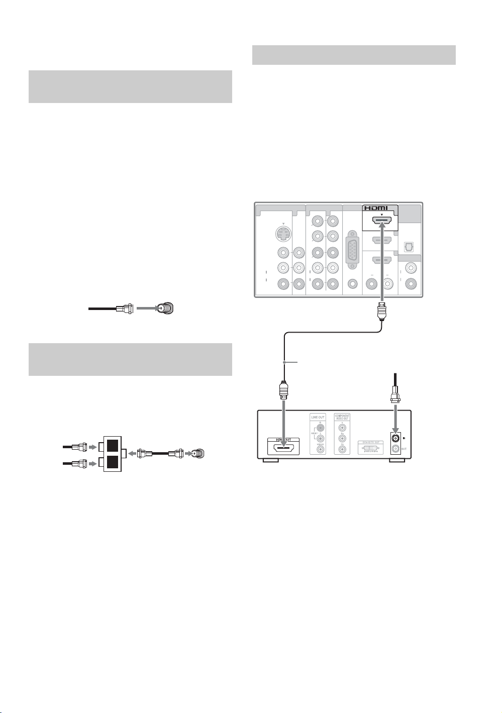
HD Cable Box/HD Satellite Box
Cable System or VHF/UHF Antenna System
You can enjoy high-definition and standarddefinition digital programming (if available in
your area) along with standard-definition analog
programming.
~
• This TV is capable of receiving unscrambled digital
programming for both cable (QAM and 8VSB) and
external VHF/UHF antenna (ATSC).
• It is strongly recommended that you connect the
CABLE/ANTENNA input using a 75-ohm coaxial
cable to receive optimum picture quality. A 300-ohm
twin lead cable can be easily affected by radio
frequency interference, resulting in signal degradation.
Cable or VHF/UHF (or VHF only)
75-ohm coaxial
cable
Cable System and VHF/UHF Antenna System
Use an optional A-B RF switch (not supplied) to
switch between the cable and over-the-air antenna
programming, as indicated below.
Rear of TV
CABLE/ANTENNA
You can enjoy high-definition programming by
subscribing to a high-definition cable service or a
high-definition satellite service. For the best
possible picture, make sure you connect this
equipment to your TV via the HDMI or
component video (with audio) input on the back of
your TV.
Shown with HDMI Connection
Rear of TV
VIDEO IN
1 3 1
S VIDEO
VIDEO
L
(MONO)
AUDIO
R
COMPONENT IN
1
Y
P
B
P
R
L
AUDIO
R
(1080p/1080i/720p/480p/480i)
PC IN
2
RGB
RL
HDMI cable
HD cable box/
HD satellite box
IN
3
4
AUD I O
DIGITAL
AUDIO
OUT
(OPTICAL)
AUDIO OUT
L
AUD I OAUD I O
R
(VAR/FIX)
CATV/Satellite
antenna cable
A-B RF switch
Cable
Antenna
A
B
CABLE/ANTENNA
Rear of TV
~
• Be sure to set the Signal Type setting to Cable or
Antenna in the Channel settings for the type of
input signal you choose (see page 46).
12
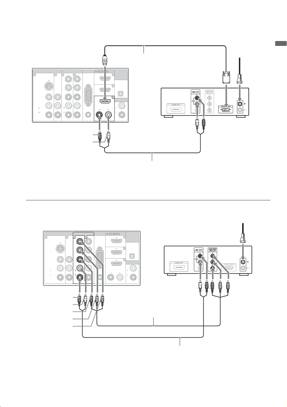
Shown with DVI Connection
CATV/Satellite
antenna cable
Rear of TV
VIDEO IN
1 3 1
S VIDEO
VIDEO
L
(MONO)
AUDIO
R
COMPONENT IN
1
Y
P
B
P
R
L
AUDIO
R
(1080p/1080i/720p/480p/480i)
PC IN
2
RGB
RL
AUD I O
IN
3
4
AUDIO OUT
L
AUD I OAUD I O
R
DIGITAL
AUDIO
OUT
(OPTICAL)
(VAR/FIX)
DVI-to-HDMI
cable
HD cable box/
HD satellite box
AUDIO-R (red)
AUDIO-L (white)
Audio cable
~
• If the equipment has a DVI jack and not an HDMI jack, connect the DVI jack to the HDMI IN 4 (with DVI-to-HDMI
cable or adapter) jack and connect the audio jack to the AUDIO IN (L/R) jacks of HDMI IN 4. For details, see
page 11.
Shown with Component Connection
Rear of TV
VIDEO IN
1 3 1
S VIDEO
VIDEO
L
(MONO)
AUDIO
R
COMPONENT IN
1
Y
P
B
P
R
L
AUDIO
R
(1080p/1080i/720p/480p/480i)
PC IN
2
RGB
RL
AUD I O
IN
3
4
AUDIO OUT
L
AUD I OAUD I O
R
DIGITAL
AUDIO
OUT
(OPTICAL)
(VAR/FIX)
HD cable box/
HD satellite box
CATV/Satellite
antenna cable
Getting Started
AUDIO-R (red)
AUDIO-L (white)
R (red)
P
B (blue)
P
Y (green)
Component video cable
Audio cable
(Continued)
13

PC
Use the TV as a monitor for your PC by connecting a HD15-HD15 cable as shown below. This TV can
also be connected to a PC with a DVI or HDMI output. (Refer to the separate Quick Setup Guide.)
Rear of TV
AUD I O
IN
3
4
AUDIO OUT
AUD I O
R
DIGITAL
AUDIO
(OPTICAL)
L
(VAR/FIX)
OUT
HD15-HD15
cable (analog
RGB)
VIDEO IN
1 3 1
S VIDEO
VIDEO
L
(MONO)
AUDIO
R
COMPONENT IN
1
Y
P
B
P
R
L
AUD I O
R
(1080p/1080i/720p/480p/480i)
Audio cable (stereo mini plugs)
PC IN
2
RGB
RL
AUDIO
~
• Connect the PC IN jack to the PC using an HD15HD15 cable with ferrite core (analog RGB) and audio
cable (see page 11).
PC Input Signal Reference Chart
After connecting the PC to the TV, set the output signal from the PC according to the supported resolutions
and timings indicated below.
Supported resolutions
Signal Horizontal
(Pixel)
VGA 640
640
720
SVGA
XGA
WXGA
SXGA
HDTV
800
800
1,024
1,024
1,024
1,280
1,280
1,280
1,360
1,280
1,920
× Ver ti ca l
(Line)
×
×
×
×
×
×
×
×
×
×
×
×
×
×
480 31.5 60 VGA
480 37.5 75 VESA
400 31.5 70 VGA-T
600 37.9 60 VESA Guidelines
600 46.9 75 VESA
768 48.4 60 VESA Guidelines
768 56.5 70 VESA
768 60.0 75 VESA
768 47.4 60 VESA
768 47.8 60 VESA
768 60.3 75
768 47.7 60 VESA
1,024 64.0 60 VESA
1,080 67.5 60 CEA-861*
• If the PC is connected to the TV and no signal has been
input from the PC for more than 30 seconds, the TV
enters the standby mode automatically (see page 52).
Horizontal
frequency (kHz)
Vertical
frequency (Hz)
Standard
~
• This TV’s PC input does not support Sync on Green or
Composite Sync.
• This TV’s PC VGA input does not support interlaced
signals.
• Your PC must support one of the above PC input
signals to display on the television.
• For the best picture quality, it is recommended to use
the signals (boldfaced) in the above chart with a 60 Hz
vertical frequency. In plug and play, signals with a 60
Hz vertical frequency will be detected automatically.
(PC reboot may be necessary.)
14
* The 1080p timing when applied to the HDMI input will
be treated as a video timing and not PC timing. This
Picture
affects
settings,
function. To view PC content set
Custom, Wide Mode
Full Pixel
.
Wide Mode
to
Full
, and
settings, and
Picture Mode
Display Area
PIP
to
to
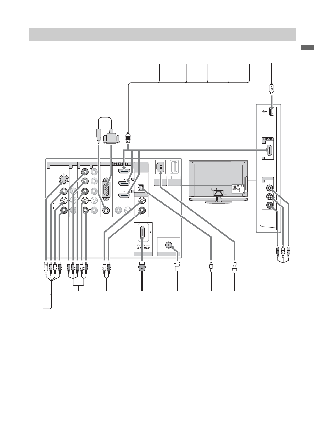
Other Equipment
VIDEO
L
(MONO)
AU DI O
R
VIDEO IN
IN
2
2
Personal
computer
Rear of TV
VIDEO IN
1 3 1
S VIDEO
VIDEO
L
(MONO)
A UDIO
R
COMPONENT IN
1
Y
P
B
P
R
L
AU DI O
R
(1080p/1080i/720p/480p/480i)
PC IN
2
RGB
AU DI O R L
IN
3
4
AU DIO OUT
L
AU DI O AU DI O
R
Blu-ray
Disc player/
“PS3”
DIGITAL
AUDIO
OUT
(OPTICAL)
(V AR/FIX)
LAN
(10/100)
DMe /
SERVICE
DVD
player
x
Digital
satellite
receiver
Digital
cable
box
Audio
system
USB
drive
Getting Started
CABLE/ANTENNA
CABLE/
ANTENNA
Digital audio
equipment
(A/V Receiver/
Home Theater)
VCR
Game
system
Digital
recorder
Analog audio
equipment
(A/V Receiver/
Home Theater)
DMPOR T
DIGITAL M EDIA
PORT adapter
for portable
player
~
• Refer to the Quick Setup Guide (supplied) when connecting other equipment to your TV.
LAN connection
Camcorder
15

4. Setting Up the Channel List
CEC CC FREEZE
– Initial Setup
The Initial Setup screen appears when you turn
on the TV for the first time.
Initial Setup
Please select a language. Language settings will apply to
on screen display as well as default audio for digital
channels. Highlight a choice and press to continue.
English
Español
Français
1 Complete your cable connections (refer to the
preceding pages and the Quick Setup Guide
provided separately) before proceeding with
the Initial Setup.
2 Use the remote control to navigate through the
Initial Setup:
V/v button:
Allows you to highlight options
where applicable.
button:
Allows you to select the
highlighted option and advance
to the next screen.
B button:
Allows you to move back to the
previous screen.
b button:
Allows you to move to the next
screen.
3 Follow the help text provided on the screen to
run Auto Program. Auto Program will
scan for available channels from the signal
source directly connected to the TV’s
CABLE/ANTENNA input.
If you receive channels from a cable box or
satellite receiver without using the CABLE/
ANTENNA input (e.g. using HDMI or
component input), skip Auto Program.
Step 1 of 6
• If the language that you have selected in the
Language setting is available from the broadcaster as
an Alternate Audio language, your TV will
automatically switch to the matching language with
the Alternate Audio feature. The Alternate Audio
option may be accessed by pressing OPTIONS on the
remote control when an alternate audio stream is
available from the broadcaster. Alternate Audio is
only available for digital programs (see page 44).
4 Set the date and time.
Begin your TV Guide On Screen
When the Initial Setup is completed, the TV will
display this screen and prompt you to set up the
electronic program guide. Follow the on screen
instructions using your remote control.
Initial Setup
Initial Setup is complete.
This TV features an electronic program guide.
Select to begin the TV Guide setup.
Next, you will see a confirmation screen with
instructions on how to acquire the TV Guide On
Screen service.
• The service is free of charge.
• Your TV acquires program listing information
while your TV is turned off.
• Allow 24 hours (some areas may take longer)
for the TV to fully receive the program listing
information.
• Once the program information is obtained by
the TV, you will be able to view a guide of up
to two days of TV programming. See page 34
on how to use the TV Guide On Screen.
s To Display TV Guide On Screen
Press GUIDE.
Setup
Step 6 of 6
~
• If you select Skip, you will be asked to disable
Channel Tuning Keys to avoid accidental input
change while using an external input; see page 50 for
details.
16
s To Run Initial Setup Again or Auto
Program at a Later Time
Select the Initial Setup feature from the XMB
™
or perform the steps described in the Initial
Setup section on page 52. To run Auto
Program, see page 46.
HDMI Settings
General Setup
Settings
Initial Setup
TV
s To Add Digital Channels
Use the Add Digital Channels feature as
described on page 46. (Useful for antenna
installations.)
~
• If you accidentally turn off the TV during the Initial
Setup process, the Initial Setup will restart from the
beginning when the TV is turned back on.
• Auto Program may be canceled while the channels
are being scanned. Press RETURN first, then press
either B/b on the remote control. Select Yes to cancel
or No to resume Auto Program.
Getting Started
17
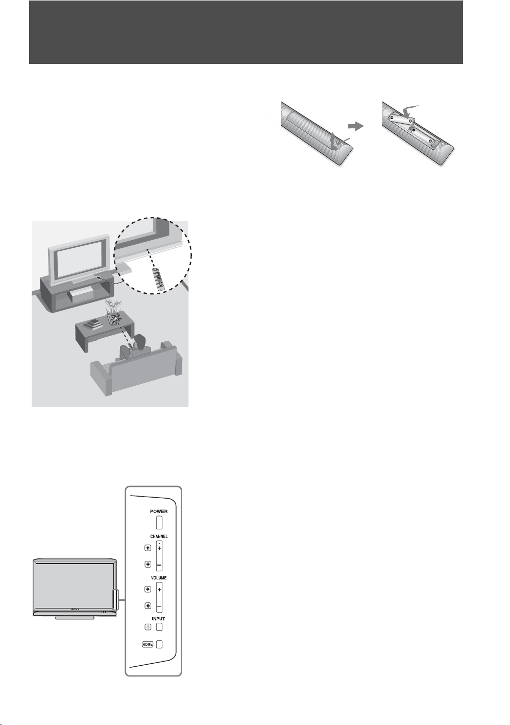
Operating the TV
Inserting Batteries into the Remote Control
Insert two size AA batteries (supplied) by matching
e and E on the batteries to the diagram inside the
battery compartment of the remote control.
When Using the Remote Control
Follow the guidelines below
• Point your remote control directly at the IR sensor
located on your TV.
• Make sure that no objects are blocking the path between
the remote control and the IR sensor on your TV.
• Fluorescent lamps can interfere with your remote
control; try turning off the fluorescent lamps.
• If you are having problems with the remote control,
reinsert or replace your batteries and make sure that they
are correctly inserted.
Push to
open
TV Controls
18
The buttons located on the side of the TV operate the same as
the corresponding buttons on the remote control.
 Loading...