

Page 1
4-269-996-F1(1)
LCD
Digital Colour TV
Operating Instructions
Getting Started
Using Your BRAVIA TV
Network Setup
Additional Information
KDL-40EX725 / 32EX725
Page 2

Introduction
Thank you for choosing this Sony product.
Before operating the TV, please read this
manual thoroughly and retain it for future
reference.
The manufacturer of this product is
Sony Corporation, 1-7-1 Konan
Minato-ku Tokyo, 108-0075 Japan.
The Authorized Representative for
EMC and product safety is Sony
Deutschland GmbH, Hedelfinger
Strasse 61, 70327 Stuttgart,
Germany. For any service or
guarantee matters please refer to the
addresses given in separate service
or guarantee documents.
Notes on Digital TV
function
• Any functions related to Digital TV
( ) will only work in countries or
areas where DVB-T (MPEG-2 and
H.264/MPEG-4 AVC) digital terrestrial
signals are broadcast or where you have
access to a compatible DVB-C (MPEG2 and H.264/MPEG-4 AVC) cable
service. Please confirm with your local
dealer if you can receive a DVB-T signal
where you live or ask your cable
provider if their DVB-C cable service is
suitable for integrated operation with
this TV.
• Your cable provider may charge a fee for
their services, or require you to agree to
its terms and conditions of business.
• This TV set complies with DVB-T and
DVB-C specifications, but compatibility
with future DVB-T digital terrestrial and
DVB-C digital cable broadcasts are not
guaranteed.
• Some Digital TV functions may not be
available in some countries/areas and
DVB-C cable may not operate correctly
with some providers.
~
• Instructions about “Installing Wall
Mount Bracket” are included within this
TV’s instructions manual.
• The illustrations used in this manual may
differ depending on your TV model.
• The illustrations of the remote used in
this manual are of the RM-ED044 unless
otherwise stated.
• Before operating the TV, please read
“Safety Information” (page 30). Retain
this manual for future reference.
Trademark information
is a registered trademark of the DVB
Project.
HDMI, the HDMI Logo, and HighDefinition Multimedia Interface are
trademarks or registered trademarks of
HDMI Licensing LLC in the United States
and other countries.
DLNA®, the DLNA Logo and DLNA
CERTIFIED® are trademarks, service
marks, or certification marks of the Digital
Living Network Alliance.
DivX® is a video file compression
technology, developed by DivX, Inc.
DivX®, DivX Certified®, and associated
logos are trademarks of DivX, Inc. and are
used under license.
ABOUT DIVX VIDEO: DivX® is a
digital video format created by DivX,Inc.
This is an official DivX Certified device
that plays DivX video. Visit
www.divx.com for more information and
software tools to convert your files into
DivX video.
ABOUT DIVX VIDEO-ON-DEMAND:
This DivX Certified® device must be
registered in order to play DivX Video-onDemand (VOD) content. To generate the
registration code, locate the DivX VOD
section in the device setup menu. Go to
vod.divx.com with this code to complete
the registration process and learn more
about DivX VOD.
Manufactured under license from Dolby
Laboratories. Dolby and the double-D
symbol are trademarks of Dolby
Laboratories.
“BRAVIA” and are
trademarks of Sony Corporation.
TrackID is a trademark or registered
trademark of Sony Ericsson Mobile
Communications AB.
Music and video recognition technology
and related data are provided by
®
Gracenote
standard in music recognition technology
and related content delivery. For more
information, please visit
www.gracenote.com.
CD, DVD, Blu-ray Disc, and music and
video-related data from Gracenote, Inc.,
copyright © 2000-present Gracenote.
Gracenote Software, copyright © 2000present Gracenote. One or more patents
owned by Gracenote apply to this product
and service. See the Gracenote website for
a nonexhaustive list of applicable
Gracenote patents. Gracenote, CDDB,
MusicID, MediaVOCS, the Gracenote
logo and logotype, and the “Powered by
Gracenote” logo are either registered
trademarks or trademarks of Gracenote in
the United States and/or other countries.
Opera® Browser from Opera Software
ASA. Copyright 1995-2010 Opera
Software ASA. All rights reserved.
Java and all Java-based trademarks and
logos are trademarks or registered
trademarks of Oracle and/or its affiliates.
Other names may be trademarks of their
respective owners.
. Gracenote is the industry
DiSEqC™ is a trademark of EUTELSAT.
This TV supports DiSEqC 1.0. This TV is
not intended for controlling motorized
antennas.
Location of the
identification label
Labels for Model No., Production Date
(month/year) and Power Supply rating (in
accordance with applicable safety
regulation) are located on the rear of the
TV or package.
GB
2
Page 3

Precautions
Viewing the TV
• Some people may experience discomfort
(such as eye strain, fatigue, or nausea)
while watching 3D video images or
playing stereoscopic 3D games. Sony
recommends that all viewers take regular
breaks while watching 3D video images
or playing stereoscopic 3D games. The
length and frequency of necessary
breaks will vary from person to person.
You must decide what works best. If you
experience any discomfort, you should
stop watching the 3D video images or
playing stereoscopic 3D games until the
discomfort ends; consult a doctor if you
believe necessary. You should also
review (i) the instruction manual of any
other device or media used with this
television and (ii) our website (http://
www.sony-europe.com/myproduct) for
the latest information. The vision of
young children (especially those under
six years old) is still under development.
Consult your doctor (such as a
pediatrician or eye doctor) before
allowing young children to watch 3D
video images or play stereoscopic 3D
games. Adults should supervise young
children to ensure they follow the
recommendations listed above.
• Do not use, store, or leave the 3D
Glasses or the battery near fire, or in
places with a high temperature, e.g., in
direct sunlight, or in sun-heated cars.
• When using the simulated 3D function,
please note that the displayed image is
modified from the original due to the
conversion done by this television.
• View the TV in moderate light, as
viewing the TV in poor light or during
long period of time, strains your eyes.
• When using headphones, adjust the
volume so as to avoid excessive levels,
as hearing damage may result.
LCD Screen
• Although the LCD screen is made with
high-precision technology and 99.99%
or more of the pixels are effective, black
dots may appear or bright points of light
(red, blue, or green) may appear
constantly on the LCD screen. This is a
structural property of the LCD screen
and is not a malfunction.
• Do not push or scratch the front filter, or
place objects on top of this TV set. The
image may be uneven or the LCD screen
may be damaged.
• If this TV set is used in a cold place, a
smear may occur in the picture or the
picture may become dark. This does not
indicate a failure. These phenomena
disappear as the temperature rises.
• Ghosting may occur when still pictures
are displayed continuously. It may
disappear after a few moments.
• The screen and cabinet get warm when
this TV set is in use. This is not a
malfunction.
• The LCD screen contains a small
amount of liquid crystal. Some
fluorescent tubes used in this TV set also
contain mercury (except for LED
backlight LCD TV). Follow your local
ordinances and regulations for disposal.
Handling and cleaning the
screen surface/cabinet of
the TV set
Be sure to unplug the mains lead
connected to the TV set from mains socket
before cleaning.
To avoid material degradation or screen
coating degradation, observe the following
precautions.
• To remove dust from the screen surface/
cabinet, wipe gently with a soft cloth. If
dust is persistent, wipe with a soft cloth
slightly moistened with a diluted mild
detergent solution.
• Do not spray water or detergent directly
on the TV set. It may drip to the bottom
of the screen or exterior parts, and may
cause a malfunction.
• Never use any type of abrasive pad,
alkaline/acid cleaner, scouring powder,
or volatile solvent, such as alcohol,
benzene, thinner or insecticide. Using
such materials or maintaining prolonged
contact with rubber or vinyl materials
may result in damage to the screen
surface and cabinet material.
• Periodic vacuuming of the ventilation
openings is recommended to ensure to
proper ventilation.
• When adjusting the angle of the TV set,
move it slowly so as to prevent the TV
set from moving or slipping off from its
table stand.
Optional Equipment
• Keep optional components or any
equipment emitting electromagnetic
radiation away from the TV set.
Otherwise picture distortion and/or noisy
sound may occur.
• This equipment has been tested and
found to comply with the limits set out in
the EMC Directive using a connection
signal cable shorter than 3 meters.
(Caution about handling the
remote control)
Notes
• Observe the correct polarity when
inserting batteries.
• Do not use different types of batteries
together or mix old and new batteries.
• Dispose of batteries in an
environmentally friendly way. Certain
regions may regulate the disposal of
batteries. Please consult your local
authority.
• Handle the remote with care. Do not
drop or step on it, or spill liquid of any
kind onto it.
• Do not place the remote in a location
near a heat source, a place subject to
direct sunlight, or a damp room.
Disposal of the TV set
Disposal of Old
Electrical &
Electronic
Equipment
(Applicable in
the European
Union and other European
countries with separate
collection systems)
This symbol on the product or on its
packaging indicates that this product shall
not be treated as household waste. Instead
it shall be handed over to the applicable
collection point for the recycling of
electrical and electronic equipment. By
ensuring this product is disposed of
correctly, you will help prevent potential
negative consequences for the
environment and human health, which
could otherwise be caused by
inappropriate waste handling of this
product. The recycling of materials will
help to conserve natural resources. For
more detailed information about recycling
of this product, please contact your local
Civic Office, your household waste
disposal service or the shop where you
purchased the product.
(Continued)
GB
3
Page 4

Disposal of
waste batteries
(applicable in the
European Union
and other
European
countries with separate
collection systems)
This symbol on the battery or on the
packaging indicates that the battery
provided with this product shall not be
treated as household waste. On certain
batteries this symbol might be used in
combination with a chemical symbol. The
chemical symbols for mercury (Hg) or
lead (Pb) are added if the battery contains
more than 0.0005% mercury or 0.004%
lead. By ensuring these batteries are
disposed of correctly, you will help
prevent potentially negative consequences
for the environment and human health
which could otherwise be caused by
inappropriate waste handling of the
battery. The recycling of the materials will
help to conserve natural resources. In case
of products that for safety, performance or
data integrity reasons require a permanent
connection with an incorporated battery,
this battery should be replaced by qualified
service staff only. To ensure that the
battery will be treated properly, hand over
the product at end-of-life to the applicable
collection point for the recycling of
electrical and electronic equipment. For all
other batteries, please view the section on
how to remove the battery from the
product safely. Hand the battery over to
the applicable collection point for the
recycling of waste batteries. For more
detailed information about recycling of
this product or battery, please contact your
local Civic Office, your household waste
disposal service or the shop where you
purchased the product.
GB
4
Page 5

GB
5
Page 6

Table of Contents
Getting Started
Checking the accessories........................................................................................................8
Inserting batteries into the remote............................................................................................8
1: Attaching the Table-Top Stand ............................................................................................8
2: Adjusting the viewing angle of the TV..................................................................................9
3: Connecting an antenna (aerial)/Set Top Box/recorder (e.g. DVD recorder) ......................10
4: Connecting audio/video devices ........................................................................................11
5: Preventing the TV from toppling over.................................................................................11
6: Bundling the cables............................................................................................................12
7: Performing the initial set-up ...............................................................................................12
Using Your BRAVIA TV
Watching the TV.....................................................................................................................15
Selecting various functions and settings (Home Menu).........................................................17
Displaying Operating Instructions (i-Manual).........................................................................19
Network Setup
Preparing a wired network .....................................................................................................21
Preparing a wireless LAN.......................................................................................................21
Setting up the Internet connection .........................................................................................22
If you cannot connect to the Internet......................................................................................23
Adjusting the server display settings......................................................................................23
Additional Information
Troubleshooting .....................................................................................................................24
Specifications......................................................................................................................... 25
Installing the Accessories (Wall-Mount Bracket)....................................................................27
Safety Information..................................................................................................................30
GB
6
Page 7
After setting up your BRAVIA TV and learning basic operations with
this manual, see the built-in manual (i-Manual) for further
explanation of the features of your TV.
This TV has a built-in manual (i-Manual).
To access the i-Manual, press i-MANUAL on the remote, and select an item. For details, see
page 19 of this manual. Contents of the i-Manual may differ depending on the model/region/area.
Contents of the i-Manual
How to Use i-Manual
“BRAVIA” TV Features
3D Feature
Presence Sensor
“BRAVIA” Internet Video
Internet Widgets
Wireless LAN Ready
“BRAVIA” Sync with “Control for HDMI”
TrackID™/Music Search/Video Search
USB HDD Recording
Watching TV
3D Feature
Digital Electronic Programme Guide
Favourites
Screen Format
Picture Mode
Text
Photos/Music/Videos
Twin Picture (PIP)
Twin Picture (P&P)
NVOD/MF
Settings/Home Menu
About the Home Menu
Settings
Display
Sound
System Settings
i-Manual
Digital Set-up
Analogue Set-up
External Inputs
Network
Product Support
Using Other Equipment/
Internet
VCR/DVD Player
Audio System
USB Device (e.g. Digital Camera)
Picture Frame
HDMI Equipment
Internet/Wireless LAN
Home Network
PC
Parts Description
Remote
TV Controls and Indicators
Terminals
Troubleshooting
Index
Bookmarks
GB
7
Page 8

Getting Started
Checking the accessories
Remote (1)
Size AAA batteries (R3 type) (2)
Table-Top Stand (1)
Fixing screws for Table-Top Stand
(M5 x 16) (3)
Assembling screws for Table-Top
Stand (M6 x 14) (3)
Hexagon wrench (1)
Operating Instructions (this manual)
and other documents
*1
Refer to the supplied Table-Top Stand leaflet to
assemble the Table-Top Stand.
*1
Inserting batteries into the remote
1: Attaching the Table-Top
Stand
1 Refer to the supplied Table-Top Stand
leaflet for proper attachment for some
TV models.
2 Place the TV set on the Table-Top
Stand.
Guide
pins
~
• Align the TV from the top, slide it in until the
guide pins cannot be seen.
3 Fix the TV to the Table-Top Stand
according to the arrow marks that
guide the screw holes using the
supplied screws.
1 Remove the protection sheet.
2 Push and slide the cover upward.
GB
8
~
• If using an electric screwdriver, set the torque at
approximately 1.5 N·m {15 kgf·cm}.
Page 9

Detaching the Table-Top Stand
from the TV
To detach the Table-Top Stand from the TV,
remove the screws fixed in step 3.
~
• Do not remove the Table-Top Stand for any
reason other than to install corresponding
accessories on the TV.
• When removing the Table-Top Stand from the
TV, lay the display face down on a stable work
surface that is larger than the TV.
• To prevent damaging the surface of the LCD
display, make sure to place a soft cloth on the
work surface.
• Be sure the TV is on the vertical position before
switching on. TV set must not powered on with
LCD panel face down to avoid uneven picture
uniformity.
2: Adjusting the viewing
angle of the TV
This TV can be adjusted within the angles as
illustrated.
Angle adjustment (Swivel)
~
• When adjusting the angle, hold the stand with one
hand to avoid having the stand slip or TV tip over.
20°
20°
Angle adjustment (Tilt)
~
• Be careful not to pinch your fingers between the
TV and stand when adjusting the angle.
20°
20°
0° - 6°
Getting Started
~
• Ensure that there are no objects in front of the TV.
IR Sensor
3D Sync Transmitter
Presence Sensor
• Do not expose the Presence Sensor to direct
sunlight or other strong light, as malfunction may
occur.
GB
9
Page 10
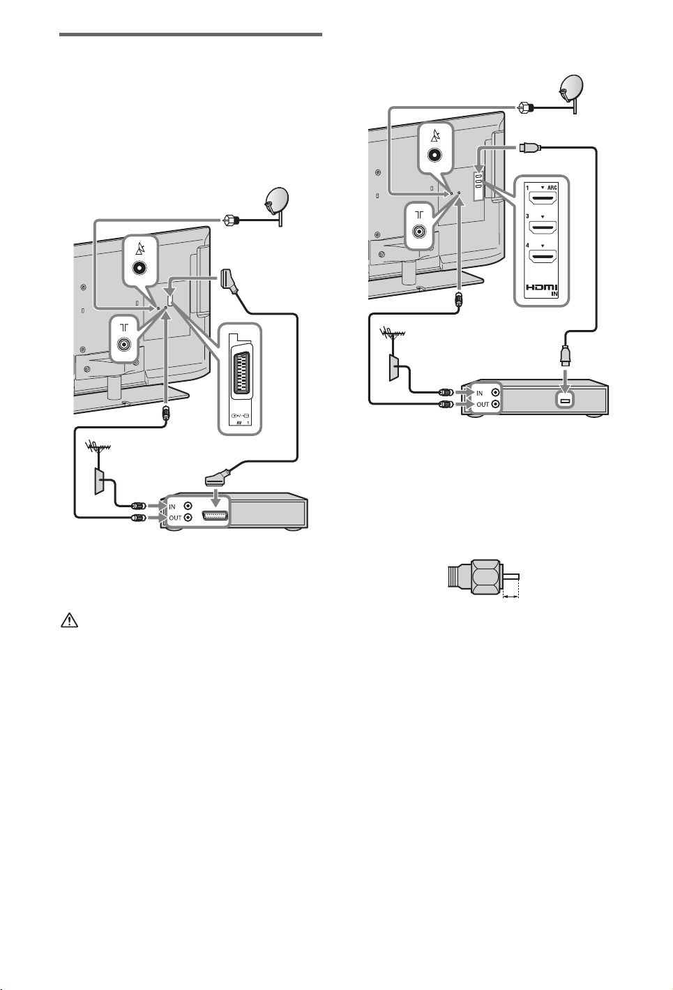
3: Connecting an antenna
(aerial)/Set Top Box/
recorder (e.g. DVD
recorder)
Connecting a Set Top Box/recorder
(e.g. DVD recorder) with SCART
Connecting a Set Top Box/recorder
(e.g. DVD recorder) with HDMI
Set Top Box/recorder (e.g. DVD recorder)
Set Top Box/recorder (e.g. DVD recorder)
~
• Right Angle Type Universal SCART Lead is
recommended for this connection.
• Screw the satellite connector softly with hand, do
not use any tool.
• TV must be switched off when connecting satellite
antenna (aerial).
Recommendation of the F type plug
The one based on the following drawing is
recommended about the F type plug.
Projection of the inner wire from the
connection part must be less than 1.5 mm.
1.5 mm max.
(Reference drawing of the F type plug)
10
GB
Page 11

4: Connecting audio/video
devices
Audio/video device
5: Preventing the TV from
toppling over
Getting Started
1 Install a wood screw (4 mm in
diameter, not supplied) in the TV stand.
2 Install a machine screw (M4 × 10, not
supplied) into the screw hole of the TV.
3 Tie the wood screw and the machine
screw with a strong cord (not supplied).
11
GB
Page 12

6: Bundling the cables
4
3
1
2
~
• Before bundling the cables, remove the cable
holder from the AC cover (see step 1 and 2).
Reuse the cable holder (see step 3) to bundle the
other cables (see step 4).
• Do not bundle the AC power cord (mains lead)
together with other cables.
7: Performing the initial
set-up
1
3
2
4
*
* When installing on the wall, attach the cable
holder under the terminals.
1 Connect the TV to your AC power
outlet (mains socket).
2 Press 1 on the TV. The = (power)
indicator will light up in green.
When you switch on the TV for the first
time, the Language menu appears on the
screen.
~
• When you turn on the TV for the first time, the
TV requires some internal processing for
optimization before you can perform the
initial setup. There will be no picture and
sound, and the timer indicator on the front of
the TV blinks orange for about 40 seconds. Do
not turn off the TV during this process.
This process has been completed at the factory
for some TVs.
12
3
Follow the instructions on the screen.
GB
Page 13

Satellite Auto Tuning:
The following procedures may be required
depending on the area:
1 Please select “Preferred Satellite” or
“General Satellite”.
2 For “Preferred Satellite”, select your
preferred operator.
“Satellite Auto Tuning” automatically
tunes in available satellite channels. Digital
Satellite Equipment Control (DiSEqC) 1.0
management allows setting of up to four
different channels. The following settings
are independent for each connection. To
set-up DiSEqC input in the “DiSEqC
Control”, use “LNB Configuration”.
1 “Scan Type” and “Advanced Settings”
(for common satellite setting- Satellite 1
to 4):
Allows you to set tuning settings in more
detail to better find the type of services you
would prefer to tune.
“Scan Type”: If no channel is found using
“Network Scan”, try “Full Scan”.
“Full Scan”: Performs a complete
frequency scan and guarantees tuning to
all possible programmes for the currently
set LNB configuration. Previously-tuned
programmes will be lost.
“Network Scan”: Performs a scan in the
transponders of a network (aka NIT
scan). Since “Network Scan” is faster
than “Full Scan”, it is recommended
when tuning to a known network
(normally associated with a satellite). A
transponder must be specified, from
which network information (other
transponders) will be retrieved.
Previously-tuned programmes will be
lost.
2 “LNB Configuration” (for each satellite
setting- Satellite 1 to 4):
In the case of a non-standard LNB (lownoise block), manual setting is available.
– In the case of a single satellite channel,
you can leave it on the initial setting.
– For two satellite channels, you need to
set “Toneburst A” (1st satellite) and
“Toneburst B” (2nd satellite) in the
“DiSEqC Control” setting.
– Or you can use DiSEqC command A
(1st satellite) and B (2nd satellite), if
your LNB or multi switch can handle
these commands.
– For four satellite channels, DiSEqC
control A, B, C, and D is required.
“LNB Low Band Frequency” and
“LNB High Band Frequency”:
– Specifies LNB frequency bands. Be
sure to check your LNB
documentation to set frequencies
(normally appears as “L.O.
frequency”).
– The default values are for a universal
LNB.
– If your LNB can handle both bands
(low and high), you can specify both.
If it handles only one, specify low
band.
“22 kHz Tone”: If your LNB is dual
band (low and high bands), set to “Auto”.
The TV will take care of everything
automatically; otherwise, set to “Off”.
“LNB Voltage”: Specifies the set
voltage for a dual polarisation LNB.
– 13/18V: default.
– 14/19V: if LNB cable is over 60m
long.
– Off: if an external power supply can be
used.
3 “Transponder” (for each satellite
setting- Satellite 1 to 4):
There is no need to set the transponder
when you select “Full Scan”.
“Scan for new services”:
– Tunes to a single transponder.
– This is an incremental scan, and it
should be used in cases when a new
transponder is added to a satellite.
– Previously-tuned programmes are kept
and found ones are added to the
program list of the satellite connection
you are editing.
1 Press HOME, then select > “Digital
Set-up” > “Satellite Auto Tuning”.
2 Follow the instruction on the Satellite
Auto Tuning.
~
• “Scan for new services” is unavailable while
performing the initial set-up.
• When you scan for the new services, please
check if the satellite signal is available.
(Continued)
13
GB
Getting Started
Page 14

Digital Auto Tuning: When you select
“Cable”, we recommend that you select
“Quick Scan” for quick tuning. Set
“Frequency” and “Network ID” according
to the information supplied from your cable
provider. If no channel is found using
“Quick Scan”, try “Full Scan” (though it
may take some time).
~
• “Full Scan” may not be available depending
on your region/country.
Programme Sorting: Changes the order of
analogue channels stored in the TV.
1 Press F/f to select the channel you want
to move to a new position, then press .
2 Press F/f to select the new position for
the channel, then press .
~
• For satellite channels, select “Satellite
Programme Sorting” in “Digital Set-up” of
“Settings” to change the order of satellite
channels in the same procedure above after
initial set-up completed.
• You can also tune channels manually.
14
GB
Page 15

Using Your BRAVIA TV
Watching the TV
Turn on the TV.
1
Press 1 on the TV to turn on the TV.
Select a mode.
2
1
Select a TV channel.
3
Using Your BRAVIA TV
2
GUIDE
3
z
• The number 5, N, PROG + and
AUDIO buttons on the remote
have a tactile dot. Use the tactile
dots as a reference when
operating the TV.
To use Digital Electronic Programme Guide
Press GUIDE in digital mode to display the
programme guide.
Use with 0-9 to select digital channels. For channel
numbers 10 and above, press the next digit quickly.
(Continued)
15
GB
Page 16

Parts and controls of the remote
Use the supplied remote to control your TV. Basic remote operations are explained here. For details
on all of the remote function, press i-MANUAL and see the built-in manual (i-Manual) (page 19).
1 :/1
Press to turn the TV on and off from standby mode.
2 i-MANUAL
Displays the built-in manual (i-Manual).
3 SYNC MENU
Displays the BRAVIA Sync Menu to operate the
BRAVIA Sync-compatible equipment that is
connected to the TV.
4 F/f/G/g/
Moves the on-screen cursor, and confirm the item.
5 OPTIONS
Displays a list of convenient functions and menu
shortcuts. The menu items vary based on the current
input and/or content.
6 Coloured buttons
When the coloured buttons are available, an operation
guide appears on the screen.
Rear of Remote Control
7 PROG/CH +/–/Number buttons
Select channels in the TV mode.
8 2 +/–
Adjusts the volume.
16
GB
Page 17

Selecting various functions and settings (Home Menu)
You can select all the features from the Home menu.
See page 18 for the Home menu map.
Press HOME.
1
Press F/f/G/g/ to select items.
2
2
1, 3
To select items in the Home menu (e.g.,
selecting “Settings”)
1 Press G/g to select “Settings”.
The contents of “Settings” are displayed on
the right.
2 Press F/f to select “Display”.
3 Press to launch the menu.
According to the screen instruction, press
F/f/G/g to select items and press to
confirm.
Press HOME to exit.
3
Using Your BRAVIA TV
(Continued)
17
GB
Page 18

Home menu map
After pressing HOME on the remote, following icons are displayed as categories. The categories are
available depending on your TV model, region, country and broadcasting conditions.
TV You can select a list of TV channels, or a programme guide.
Media You can enjoy photo/music/video content via USB devices or
the home network.
Inputs You can select equipment connected to the TV.
Favourites/History Provides quick access to your frequently used and recently
viewed items, such as TV channels, external inputs or your
media files.
Settings Contains all of the necessary configurations to customise
your TV settings.
Widgets Provides access to Widgets.
Applications You can enjoy various applications such as “Music Search”,
“Internet Browser”, etc.
Qriocity Enable access to the “Qriocity” online service.
Internet Content You can enjoy Internet content services.
Recommendations Presents recommendations for programmes you may like,
based on your viewing history.
Recordings You can enjoy timer recordings to a connected USB HDD
device, and selection of recorded content to play.
18
GB
Page 19

Displaying Operating Instructions (i-Manual)
Operating instructions are built into your BRAVIA TV and can be displayed on the screen.
To learn more about your TV features, access your i-Manual with the touch of a button.
Press i-MANUAL.
1
1
Press F/f/G/g/ to select items.
2
2
Using Your BRAVIA TV
To select items in the i-Manual
1 Press F/f to select an item.
The contents in the item are displayed on the
right as the second layer.
2 Press g to move to the second layer.
3 Press F/f to select an item from the second
layer.
A digest of the item is displayed on the right.
If the third layer is available, repeat this step
to display the digest of the item.
4 Press g to select an item.
The content is displayed.
(Continued)
19
GB
Page 20

Description of the i-Manual screen
Press G to go back to the previous page
Press f to go to the next page
Page number/Total page number
Press RETURN to go back to the previous page
Press to launch the function
~
• This will be displayed only when the function is available.
To use the bookmark
The i-Manual has a bookmark function. Pages can be bookmarked with coloured buttons, according
to the instructions at the bottom of the screen. To access your registered bookmarks, go to the top
page of the i-Manual and select “Bookmarks”.
To memorise the last displayed page
i-Manual memorises the last displayed page. When in the i-Manual screen, press i-MANUAL to
return to the TV screen. If you press i-MANUAL again, the information you saw last time appears.
For viewing from the top page of the i-Manual, return to the top page according to the instructions
on the screen, or press HOME and select “i-Manual”of “Settings” in the Home menu.
~
• Last page memory is automatically reset when you switch the TV to standby mode.
GB
20
Page 21

Network Setup
When you connect this TV to the Internet, you
can enjoy multiple functions: displaying a
photograph that shows its location on the map,
enjoying Internet video, etc. For details on the
functions, refer to the i-Manual.
~
• You will need to contract with an Internet service
provider to connect to the Internet.
Preparing a wired network
Internet
Modem
with router
functions
or
Preparing a wireless LAN
Wireless LAN Ready lets you easily access the
Internet and your home network with the USB
Wireless LAN Adapter UWA-BR100 (as of
January 2010). By inserting the USB Wireless
LAN Adapter into your TV’s USB port, you
can easily create a cable-free network. Before
setting up the wireless LAN function of the
TV, be sure to set up a wireless LAN router.
Network Setup
TV
~
• For LAN connections, use a Category 7 cable (not
supplied).
Router
Modem
Internet
~
• The USB Wireless LAN Adapter is available as an
optional accessory, depending on your TV model.
21
GB
Page 22

Setting up the Internet connection
For security purpose, “WPS (PIN)” provides a
PIN code for your router. PIN code is renewed
every time you select “WPS (PIN)”.
Using the network feature you can connect the
TV to the Internet. The set-up procedure
differs depending on the type of network and
LAN router. Before setting up the Internet
connection, be sure to set up a LAN router.
Check your wireless LAN environment using
the following chart.
Wireless LAN
Secure Wireless LAN? NO
Type 3
k
YES m
Do you use a wireless LAN
router compatible with Wi-Fi
Protected Set-up (WPS)?
YES m
Type 1*
Wired LAN
* Type 1 is easier to set up if your router has an
automatic setting button, e.g. Air Station OneTouch Secure System (AOSS). Most of the latest
routers have this function. Check your router.
, Type 4
NO
k
Type 2
1 Press HOME, then select >
“Network” > “Network Set-up”.
2 Select “Wireless Set-up”.
3 Select “WPS (Push Button)” for Push
Button method or “WPS (PIN)” for
PIN method.
~
• Button name of the WPS may differ
depending on the router (e.g. AOSS button).
4 Follow the instructions on the set-up
screen.
Type 2: Secured network
without Wi-Fi Protected Set-up
(WPS)
To set up a wireless LAN, SSID (wireless
network name) and security key (WEP or
WPA key) will be required. If you do not know
them, consult the instruction manual of your
router.
1 Press HOME, then select >
“Network” > “Network Set-up”.
Type 1: Follow the configuration for “Secured
Network with Wi-Fi Protected Set-up (WPS)”.
Type 2: Follow the configuration for “Secured
Network without Wi-Fi Protected Set-up
(WPS)”.
Type 3: Follow the configuration for
“Unsecured Network with Any Type of
Wireless LAN Router”.
Type 4: Follow the configuration for “Wired
network set-up”.
Type 1: Secured network with
Wi-Fi Protected Set-up (WPS)
The WPS standard makes security of a wireless
home network as straightforward as pressing
the WPS button on the wireless LAN router.
Before setting up a wireless LAN, check the
location of the WPS button on the router and
verify how to use it.
GB
22
2 Select “Wireless Set-up”.
3 Select “Scan”, then select a network
from the list of scanned wireless
networks.
4 Follow the instructions on the set-up
screen.
~
• If you use WPS for network set-up, the security
settings of the wireless LAN router activate, and
any equipment previously connected to the
wireless LAN in a non-secure status will be
disconnected from the network.
In this case, activate the security settings of the
disconnected equipment and then reconnect. Or,
you can deactivate the security settings of the
wireless LAN router, and then connect the
equipment to a TV in a non-secure status.
Page 23

Type 3: Unsecured network
with any type of wireless LAN
router
To set up a wireless LAN, SSID (wireless
network name) will be required.
1 Press HOME, then select >
“Network” > “Network Set-up”.
2 Select “Wireless Set-up”.
3 Select “Scan”, then select a network
from the list of scanned wireless
networks.
4 Follow the instructions on the set-up
screen.
~
• Security key (WEP or WPA key) will not be
required because you do not need to select any
security method in this procedure.
Type 4: Wired network set-up
Enter the respective alphanumeric values for
your router if necessary. The items that need to
be set (e.g. IP Address, Subnet Mask, DHCP)
may differ depending on the Internet service
provider or router. For details, refer to the
instruction manuals provided by your Internet
service provider, or those supplied with the
router.
If you cannot connect to the Internet
Use the diagnosis to check possible causes for
network connection failures, and settings.
1 Press HOME, then select >
“Network” > “Network Set-up”.
2 Select “View Network Status”.
3 Select “Check Connection”.
This may take several minutes. You
cannot cancel the diagnosis after
selecting “Check Connection”.
Network Setup
Adjusting the server display settings
You can select home network servers to be
displayed on the Home Menu. Up to 10 servers
can be displayed in the Home Menu
automatically.
1 Press HOME, then select >
“Network” > “Home Network Setup”.
2 Select “Server Display Settings”.
3 Select the server you want to display on
the Home Menu, and adjust the
settings.
1 Press HOME, then select >
“Network” > “Network Set-up”.
2 Select “Wired Set-up”.
3 Select “Auto” to set the IP Address and
proxy server automatically, or
“Custom” to set them manually.
4 Follow the instructions on the set-up
screen.
Viewing the network status
You can confirm your network status.
1 Press HOME, then select >
“Network” > “Network Set-up”.
2 Select “View Network Status”.
If you cannot connect to your home
network
The TV detects if the server is being correctly
recognised when you cannot connect it to your
home network. If the diagnostic results
indicate a failure, check possible causes, and
network connections and settings.
1 Press HOME, then select >
“Network” > “Home Network Setup”.
2 Select “Server Diagnostics”.
The server diagnostic starts. When the
server diagnostic is complete, the
diagnostic result list appears.
GB
23
Page 24

Additional Information
Troubleshooting
When the 1 (standby) indicator is flashing, count how many times it flashes (interval
time is three seconds).
Press 1 on the TV to turn it off, disconnect the AC power cord (mains lead), and inform your dealer
or Sony service centre of how the indicator flashes (number of flashes).
When the 1 (standby) indicator is not flashing, check the items in the tables as
follows.
Also refer to “Troubleshooting” in the i-Manual. If the problem persists, have your TV serviced by
qualified service personnel.
Condition Explanation/Solution
There is no picture (screen
is dark) and no sound.
Tiny black points and/or
bright points appear on the
screen.
Some programmes cannot
be tuned.
The TV turns off
automatically (the TV
enters standby mode).
The remote does not
function.
The “Parental Lock”
password has been
forgotten.
The TV surrounds become
warm.
• Check the antenna (aerial)/cable connection.
• Connect the TV to the AC power (mains), and press 1 on the TV.
• If the 1 (standby) indicator lights up in red, press "/1.
• The screen is composed of pixels. Tiny black points and/or bright
points (pixels) on the screen do not indicate a malfunction.
• Check the antenna (aerial) or dish.
• The satellite cable might be short-circuited or there might be
connection problems of the cable. Check the cable and connection
and then turn the TV off with the Mains power On / Off switch,
and turn it on again.
• The frequency you entered is out of range. Consult the received
satellite broadcasting company.
• Check if the “Sleep Timer” is activated, or confirm the
“Duration” setting of “On Timer”.
• Check if the “Idle TV Standby” is activated.
• Check if the “Presence Sensor” is activated. When no viewer is
detected in front of the TV for a preset time, the picture
automatically turns off, while leaving only the TV sound on.
Additionally, after 30 minutes in picture off mode, the TV will
switch to standby mode.
• Replace the batteries.
• Your TV may be in SYNC mode.
Press SYNC MENU, select “TV Control” and then select “Home
(Menu)” or “Options” to control the TV.
• Enter 9999 for the PIN code. (PIN code 9999 is always accepted.)
• When the TV is used for an extended period, the TV surrounds
become warm.
You may feel hot when touching there by the hand.
24
GB
Page 25

Specifications
System
Panel system
TV system
Colour/video system
Channel coverage
Sound output
Input/Output jacks
Antenna (aerial) cable
Satellite antenna (aerial)
/ AV1
AV2
/ COMPONENT IN
HDMI IN1, 2, 3, 4
DIGITAL AUDIO OUT
(OPTICAL)
AUDIO OUT / i
PC IN
1, 2 (HDD REC)
LAN
LCD (Liquid Crystal Display) Panel
Analogue: Depending on your country/area selection: B/G/H, D/K, L, I, M
Digital: DVB-T/DVB-C
Satellite: DVB-S/DVB-S2
Analogue: PAL, PAL60 (only video input), SECAM, NTSC3.58, NTSC4.43 (only video input)
Digital: MPEG-2 MP@ML/HL, H.264/MPEG-4 AVC MP/HP@L4
Analogue: VHF: E2–E12/UHF: E21–E69/CATV: S1–S20/HYPER: S21–S41
D/K: R1–R12, R21–R69/L: F2–F10, B–Q, F21–F69/I: UHF B21–B69/M: A2-A13, A14-A79
Digital: VHF/UHF
Satellite: IF Frequency 950-2150 MHz
10 W + 10 W
75 ohm external terminal for VHF/UHF
Female F-Type Connector IEC169-24, 75 ohm.
DiSEqC 1.0, LNB 13V/18V & 22 KHz tone
21-pin scart connector (CENELEC standard) including audio/video input, RGB input and TV audio/video
output.
Video input (phono jack)
Supported formats: 1080p, 1080i, 720p, 576p, 576i, 480p, 480i
Audio input (phono jacks)
Video: 1080/24p/30p, 1080p, 1080i, 720/24p/30p, 720p, 576p, 576i, 480p, 480i
Audio: Two channel linear PCM: 32, 44.1 and 48 kHz, 16, 20 and 24 bits, Dolby Digital
Analogue audio input (minijack) (HDMI IN4 only)
PC Input
ARC (Audio Return Channel) (HDMI IN1 only)
Digital optical jack (Two channel linear PCM, Dolby Digital)
Audio output (phono jacks)
Headphones jack
PC Input (Mini D-sub 15-pin)
PC audio input (minijack)
USB port, USB HDD device port ( 2 only)
CAM (Conditional Access Module) slot
10BASE-T/100BASE-TX connector (Depending on the operating environment of the network,
connection speed may differ. 10BASE-T/100BASE-TX communication rate and communication quality
are not guaranteed for this TV.)
Additional Information
(Continued)
25
GB
Page 26

Model name KDL- 40EX725 32EX725
Power and others
Power requirements
Energy Efficiency Class
Screen size (measured
220 V – 240 V AC, 50 Hz
AB
Approx. 101.6 cm/40 inches Approx. 80.1 cm/32 inches
diagonally)
Power
consumption
in “Home”/
“Standard”
64.0 W 59.0 W
mode
in “Shop”/
121 W 101 W
“Vivid” mode
Average annual energy
consumption*
Standby power
consumption*
1
2
Display resolution
93 kWh 86 kWh
0.25 W (15 W in software/EPG update mode) 0.25 W (16 W in software/EPG update mode)
1,920 dots (horizontal) × 1,080 lines (vertical)
Dimensions (Approx.) (w × h × d)
with Table-Top Stand
without Table-Top Stand
94.3 × 61.6 × 25.0 cm 75.5 × 51.0 × 21.6 cm
94.3 × 58.6 × 4.2 cm 75.5 × 48.0 × 4.2 cm
Mass (Approx.)
with Table-Top Stand
without Table-Top Stand
Supplied accessories
Optional accessories
Operating temperature
Operating humidity
14.4 kg 10.4 kg
11.2 kg 7.9 kg
See “Checking the accessories” (page 8).
Wall-Mount Bracket: SU-WL500
3D Glasses: TDG-BR250/TDG-BR200/TDG-BR100/TDG-BR50
USB Wireless LAN Adapter
0 ºC – 40 ºC
10% – 80% RH (non-condensing)
*1Energy consumption per year, based on the power consumption of the television operating 4 hours per day
for 365 days. The actual energy consumption will depend on how the television is used.
2
Specified standby power is reached after the TV finishes necessary internal processes.
*
Design and specifications are subject to change without notice.
26
GB
Page 27

Installing the Accessories (Wall-Mount Bracket)
To Customers:
When using the SU-WL500 Wall-Mount Bracket, the space between the wall and the TV will be
6 cm. Use this space to route cables to the TV.
6 cm
Wall
For product protection and safety reasons, Sony strongly recommends that installing of your TV be
performed by Sony dealers or licensed contractors. Do not attempt to install it yourself.
To Sony Dealers and Contractors:
Provide full attention to safety during the installation, periodic maintenance and examination of this
product.
Your TV can be installed using the SU-WL500 (page 28) Wall-Mount Bracket (sold separately).
• Refer to the Instructions supplied with the Wall-Mount Bracket to properly carry out the
installation.
• Refer to “Detaching the Table-Top Stand from the TV” (page 9).
Sufficient expertise is required for installing this product, especially to determine the strength of
the wall for withstanding the TV’s weight. Be sure to entrust the attachment of this product to the
wall to Sony dealers or licensed contractors and pay adequate attention to safety during the
installation. Sony is not liable for any damage or injury caused by mishandling or improper
installation.
Additional Information
When installing the TV on the wall, remove the screws from the rear of the TV. (They are fastened
in the screw holes for wall mounting.) Be sure to store the removed screws in a safe place, keeping
them away from children.
×
2
×
2
Soft cloth
~
• When removing the Table-Top Stand from the TV, lay the display face down on a stable work surface that is
larger than the TV.
• To prevent damaging the surface of the LCD display, make sure to place a soft cloth on the work surface.
(Continued)
27
GB
Page 28

SU-WL500
SU-WL500
Mounting
Hook
×
4
Soft cloth
~
• Attach the Mounting Hook using the four screws supplied with the Wall-Mount Bracket.
• When attaching the Table-Top Stand again, be sure to fasten the screws (previously removed) to the original
holes on the rear of the TV.
Screw
(+PSW
6 × 16)
Screw and Hook locations diagram/table
Model Name
KDL-
40EX725 e, j b
32EX725 e, g c
Screw location Hook location
SU-WL500 SU-WL500
SU-WL500
Screw location
When installing the Mounting Hook on the
TV.
Hook location
When installing the TV onto the Base Bracket.
a
b
c
28
GB
Page 29

TV installation dimensions table
1 SU-WL500
F
H
G
B
A
E
C
D
Screen centre point
Unit: cm
Model
Name
KDL-
40EX725
32EX725
Display
dimensions
A B C D E F G H
94.3 58.6 15.7 46.5 9.1 26.1 54.6 47.2
75.5 48.0 16.1 41.6 9.1 24.1 44.6 42.7
Screen
centre
dimension
Angle (0°) Angle (20°)
Length for each mounting angle
Figures in the table may differ slightly depending on the installation.
WARNING
The wall that the TV will be installed should be capable of supporting a weight of at least four times that of the
TV. Refer to “Specifications” (page 25-26) for its weight.
Additional Information
29
GB
Page 30

Safety Information
Installation/Set-up
Install and use the TV set in accordance
with the instructions as follows in order to
avoid any risk of fire, electrical shock or
damage and/or injuries.
Installation
• The TV set should be installed near an
easily accessible mains socket.
• Place the TV set on a stable, level
surface.
• Only qualified service personnel should
carry out wall installations.
• For safety reasons, it is strongly
recommended that you use Sony
accessories, including:
– Wall Mount Bracket:
SU-WL500
• Be sure to use the screws supplied with
the Wall-mount bracket when attaching
the mounting hooks to the TV set. The
supplied screws are designed so that they
are 8 mm to 12 mm in length when
measured from the attaching surface of
the mounting hook.
The diameter and length of the screws
differ depending on the Wall-mount
bracket model.
Use of screws other than those supplied
may result in internal damage to the TV
set or cause it to fall, etc.
8 mm - 12 mm
Screw (supplied with the
Wall-mount bracket)
Mounting Hook
Hook attachment on rear
of TV set
Transporting
• Before transporting the TV set,
disconnect all cables.
• Two or three people are needed to
transport a large TV set.
• When transporting the TV set by hand,
hold it as shown in the illustration. Do
not put stress on the LCD panel and the
frame around the screen.
Ventilation
• Never cover the ventilation holes or
insert anything in the cabinet.
• Leave space around the TV set as shown
below.
• It is strongly recommended that you use
a Sony wall-mount bracket in order to
provide adequate air-circulation.
Installed on the wall
30 cm
10 cm 10 cm
Leave at least this space around
the set.
10 cm
Installed with stand
30 cm
10 cm
Leave at least this space around
the set.
• To ensure proper ventilation and prevent
the collection of dirt or dust:
– Do not lay the TV set flat, install
upside down, backwards, or
sideways.
– Do not place the TV set on a shelf,
rug, bed or in a closet.
– Do not cover the TV set with a cloth,
such as curtains, or items such as
newspapers, etc.
– Do not install the TV set as shown
below.
Air circulation is blocked.
Wall Wall
10 cm
6 cm
Mains lead
Handle the mains lead and socket as
follows in order to avoid any risk of fire,
electrical shock or damage and/or injuries:
– Use only mains leads supplied by
Sony, not other suppliers.
– Insert the plug fully into the mains
socket.
– Operate the TV set on a 220-240 V AC
supply only.
– When wiring cables, be sure to unplug
the mains lead for your safety and take
care not to catch your feet on the
cables.
– Disconnect the mains lead from the
mains socket before working on or
moving the TV set.
– Keep the mains lead away from heat
sources.
– Unplug the mains plug and clean it
regularly. If the plug is covered with
dust and it picks up moisture, its
insulation may deteriorate, which
could result in a fire.
Notes
• Do not use the supplied mains lead on
any other equipment.
• Do not pinch, bend, or twist the mains
lead excessively. The core conductors
may be exposed or broken.
• Do not modify the mains lead.
• Do not put anything heavy on the mains
lead.
• Do not pull on the mains lead itself when
disconnecting the mains lead.
• Do not connect too many appliances to
the same mains socket.
• Do not use a poor fitting mains socket.
Prohibited Usage
Do not install/use the TV set in locations,
environments or situations such as those
listed below, or the TV set may
malfunction and cause a fire, electrical
shock, damage and/or injuries.
Location:
• Outdoors (in direct sunlight), at the
seashore, on a ship or other vessel, inside
a vehicle, in medical institutions,
unstable locations, near water, rain,
moisture or smoke.
• If the TV is placed in the changing room
of a public bath or hot spring, the TV
may be damaged by airborne sulfur, etc.
• When transporting the TV set, do not
subject it to jolts or excessive vibration.
• When transporting the TV set for repairs
or when moving, pack it using the
original carton and packing material.
GB
30
• For best picture quality, do not expose
the screen to direct illumination or
sunlight.
• Avoid moving the TV from a cold area
to a warm area. Sudden room
temperature changes may cause moisture
condensation. This may cause the TV to
show poor picture and/or poor colour.
Should this occur, allow moisture to
evaporate completely before powering
the TV on.
Page 31

Environment:
• Places that are hot, humid, or
excessively dusty; where insects may
enter; where it might be exposed to
mechanical vibration, near flammable
objects (candles, etc). The TV set shall
not be exposed to dripping or splashing
and no objects filled with liquids, such
as vases, shall be placed on the TV.
• Do not place the TV in a humid or dusty
space, or in a room with oily smoke or
steam (near cooking tables or
humidifiers). Fire, electric shock, or
warping may result.
• Do not install the TV in places subject to
extreme temperature such as in direct
sunlight, near a radiator or a heating
vent. The TV may overheat in such
condition which can cause deformation
of the enclosure and/or TV malfunction.
Situation:
• Do not use when your hands are wet,
with the cabinet removed, or with
attachments not recommended by the
manufacturer. Disconnect the TV set
from mains socket and aerial during
lightning storms.
• Do not install the TV so that it sticks out
into an open space. Injury or damage
from a person or object bumping into the
TV may result.
For children
• Do not allow children to climb on the
TV set.
• Keep small accessories out of the reach
of children, so that they are not
mistakenly swallowed.
If the following problems
occur...
Turn off the TV set and unplug the mains
lead immediately if any of the following
problems occur.
Ask your dealer or Sony service centre to
have it checked by qualified service
personnel.
When:
– Mains lead is damaged.
– Poor fitting of mains socket.
– TV set is damaged by being dropped,
hit or having something thrown at it.
– Any liquid or solid object falls through
openings in the cabinet.
Warning
To prevent the spread of fire, keep candles
or other open flames away from this
product at all time.
Additional Information
Broken pieces:
• Do not throw anything at the TV set. The
screen glass may break by the impact
and cause serious injury.
• If the surface of the TV set cracks, do
not touch it until you have unplugged the
mains lead. Otherwise electric shock
may result.
When not in use
• If you will not be using the TV set for
several days, the TV set should be
disconnected from the mains for
environmental and safety reasons.
• As the TV set is not disconnected from
the mains when the TV set is just turned
off, pull the plug from the mains to
disconnect the TV set completely.
• However, some TV sets may have
features that require the TV set to be left
in standby to work correctly.
31
GB
Page 32

For useful information about Sony products
© 2011 Sony Corporation
4-269-996-F1(1)
 Loading...