

Sony KDL-46EX405, KDL-32EX405, KDL-32EX306, KDL-32EX305, KDL-40EX405 User Manual
...
SERVICE MANUAL
HISTORY INFORMATION FOR THE FOLLOWING MANUAL:
SERVICE MANUAL
AZ1-L Chassis
ORIGINAL MANUAL ISSUE DATE: 2/2010
Version Date Subject
1.0 2/2010 No revisions or updates
LCD Digital Color TV
9-888-294-01
SERVICE MANUAL
SERVICE MANUAL
AZ1-L Chassis
Self Diagnosis
Supported model
LCD Digital Color TV
9-888-294-01
MODEL LIST
MODEL COLOR COMMANDER DESTINATION MODEL COLOR COMMANDER DESTINATION
KDL-32EX305 BLACK RM-YD047 ARGENTINA
KDL-40EX405 BLACK RM-YD047 ARGENTINA
KDL-32EX305 BLACK RM-YD047 LATIN AMERICA
KDL-32EX306 BLACK RM-YD047 ARGENTINA
KDL-32EX306 BLACK RM-YD047 LATIN AMERICA
KDL-32EX405 BLACK RM-YD047 ARGENTINA
KDL-32EX405 BLACK RM-YD047 LATIN AMERICA
KDL-40EX405 BLACK RM-YD047 LATIN AMERICA
KDL-40EX406 BLACK RM-YD047 ARGENTINA
KDL-40EX406 BLACK RM-YD047 LATIN AMERICA
KDL-46EX405 BLACK RM-YD047 ARGENTINA
KDL-46EX405 BLACK RM-YD047 LATIN AMERICA

TABLE OF CONTENTS
Specifi cations..................................................................................................................................................................................1
Warnings and Cautions ..................................................................................................................................................................3
Safety-Related Warning ..................................................................................................................................................................4
Safety Check-Out ............................................................................................................................................................................5
Self Diagnosis Functions ...............................................................................................................................................................7
SEC 1. Disassembly/Part Number Information ..........................................................................................................................11
1-1. Table-Top Stand Assembly Removal ............................................................................................................................11
1-2. Rear Cover and Vesa Bracket Removal ...................................................................................................................... 12
1-3. AC Inlet, Speaker Brackets and Loudspeakers Removal ............................................................................................ 13
1-4. G2LE/G2HE/GD2 (Power) Board, BAL Board, LCD Panel, and HLR Board Removal ............................................... 14
1-5. Cleaning the LCD Panel .............................................................................................................................................. 15
1-6. Screw Legend .............................................................................................................................................................. 15
1-7. Connectors .................................................................................................................................................................. 16
1-7-1. All Except KDL-46EX405 ..................................................................................................................................................... 16
1-7-2. KDL-46EX405 Only ............................................................................................................................................................. 16
1-8. Accessories & Packing ................................................................................................................................................ 17
1-9. Miscellaneous .............................................................................................................................................................. 17
1-10. Remote Commander ................................................................................................................................................... 17
SEC 2. Service Adjustments ........................................................................................................................................................18
2-1. Accessing Service Adjustment Mode .......................................................................................................................... 18
2-1-1. Viewing the Service Menus ................................................................................................................................................. 19
2-1-2. Using the Remote Commander to View or Change Service Data ....................................................................................... 20
KDL-32EX305/32EX306/32EX405/40EX405/40EX406/46EX405 i

TABLE OF CONTENTS
2-2. Adjustments After Replacing the BAL Board or LCD Panel ......................................................................................... 20
2-2-1. Updating the Software ......................................................................................................................................................... 20
2-2-2. Selecting the Model ............................................................................................................................................................. 21
2-2-3. Setting the Destination ......................................................................................................................................................... 22
2-2-4. Selecting the TV Color ......................................................................................................................................................... 22
2-2-5. Verifying the Model and Panel Information .......................................................................................................................... 23
2-2-6. Reconnecting All Cables ...................................................................................................................................................... 24
2-3. White Balance Adjustments ......................................................................................................................................... 25
2-4. Resetting the TV to Factory Condition ......................................................................................................................... 26
2-4-1. Resetting the TV to Factory Condition Using Service Mode ................................................................................................ 26
SEC 3. Diagrams ...........................................................................................................................................................................27
3-1. Circuit Boards Location ............................................................................................................................................... 27
3-2. Block Diagram ............................................................................................................................................................. 28
KDL-32EX305/32EX306/32EX405/40EX405/40EX406/46EX405 ii
SPECIFICATIONS
Sistema
Sistema de TV
Cobertura de canales VHF: 2-13, UHF: 14-69
Sistema del panel Panel LCD (pantalla de cristal líquido)
Salida de bocinas 10 W + 10 W
Tomas de entrada/salida
CABLE/ANTENNA
(Cable/Antena)
VIDEO IN 1/2/3
(Entrada de video 1/2/3)
COMPONENT IN 1/2
(Entrada de componente 1/2)
HDMI IN 1/2/3/4
(Entrada HDMI 1/2/3/4)
AURICULAR Minitoma estéreo
AUDIO OUT (Salida de audio) 500 mVrms (típico)
DIGITAL AUDIO OUT
(OPTICAL)
(Salida de audio digital óptica)
PC IN (Entrada de PC) Subminiatura D de 15 contactos, RGB anal
PC/HDMI 4 AUDIO IN
(Entrada de audio de PC/HDMI 4)
LAN Conector 10BASE-T/100BASE-TX
*1 Para conexiones LAN, utilice un cable 10BASE-T/100BASE-TX de categoría 7 (no se suministra).
• La disponibilidad de los accesorios opcionales dependerá de las existencias.
• El diseño y las especificaciones están sujetos a cambios sin previo aviso.
Digital: SBTVD
CATV (Análogo): 1-125
Terminal externo de 75 ohmios para entrada de señal de radiofrecuencia
VIDEO / AUDIO
YP
BPR (video componente)
Formato de señal:
AUDIO
HDMI: Video:
HDMI:
AUDIO (HDMI IN 4)
Señal de audio óptica digital PCM/Dolby Digital
Minitoma estéreo
(La velocidad de la conexión podría variar en función del entorno de red. No se garantizan la tasa de
comunicación ni la calidad de comunicación 10BASE-T/100BASE-TX para este TV.)*
(DLNA está disponible únicamente
(para los modelos series EX406/EX405/EX306/EX305)
480i, 480p, 576i, 576p, 720p, 1080i, 1080p
480i, 480p, 576i, 576p, 720p, 1080i, 1080p, 1080/24p
Audio: PCM lineal de dos canales 32; 44,1 y 48 kHz, 16, 20 y 24 bits, Dolby Digital
ó
gico
.elbitapmoc otamrof le arap launaM-i le etlusnoCANLD/BSU
1
KDL-32EX305/32EX306/32EX405/40EX405/40EX406/46EX405 1
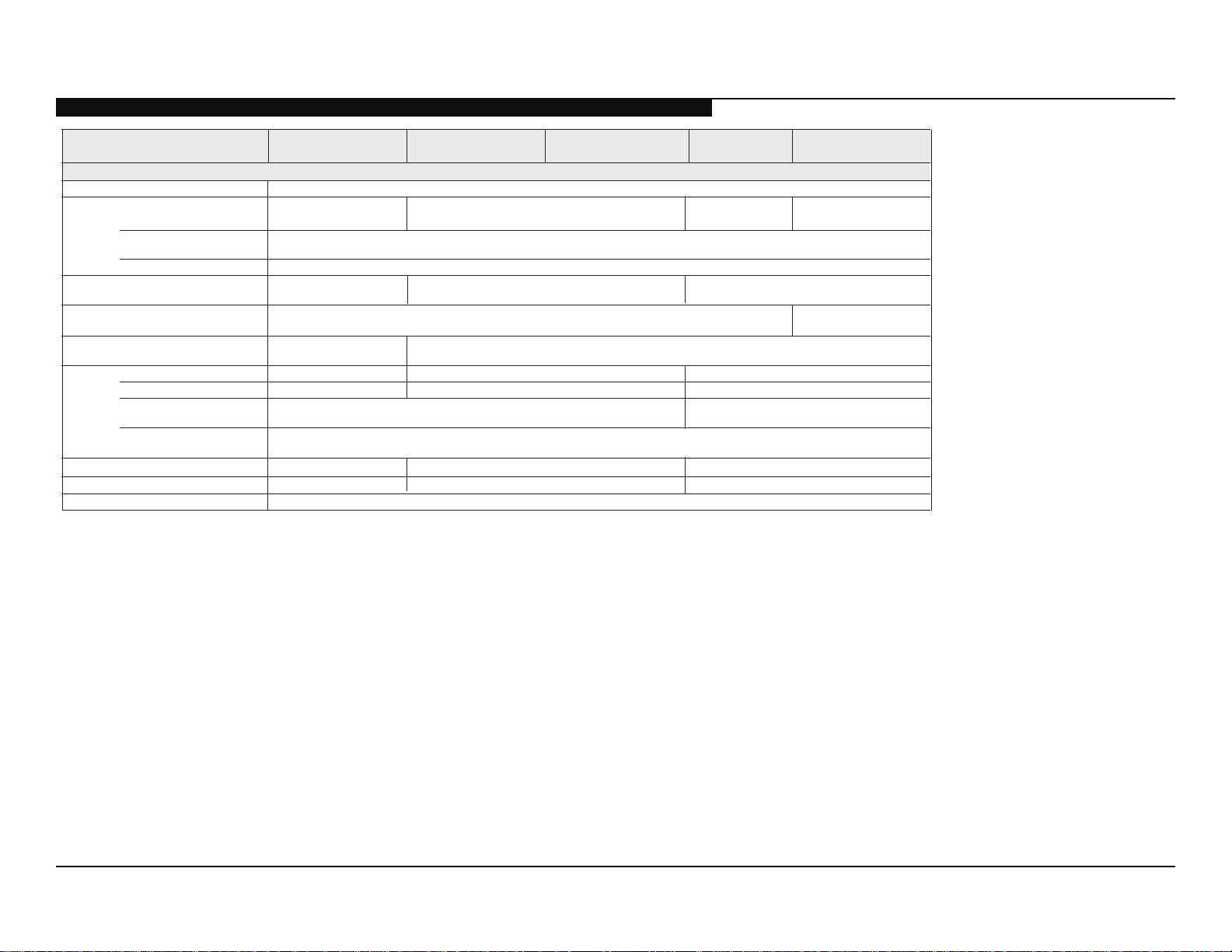
SPECIFICATIONS
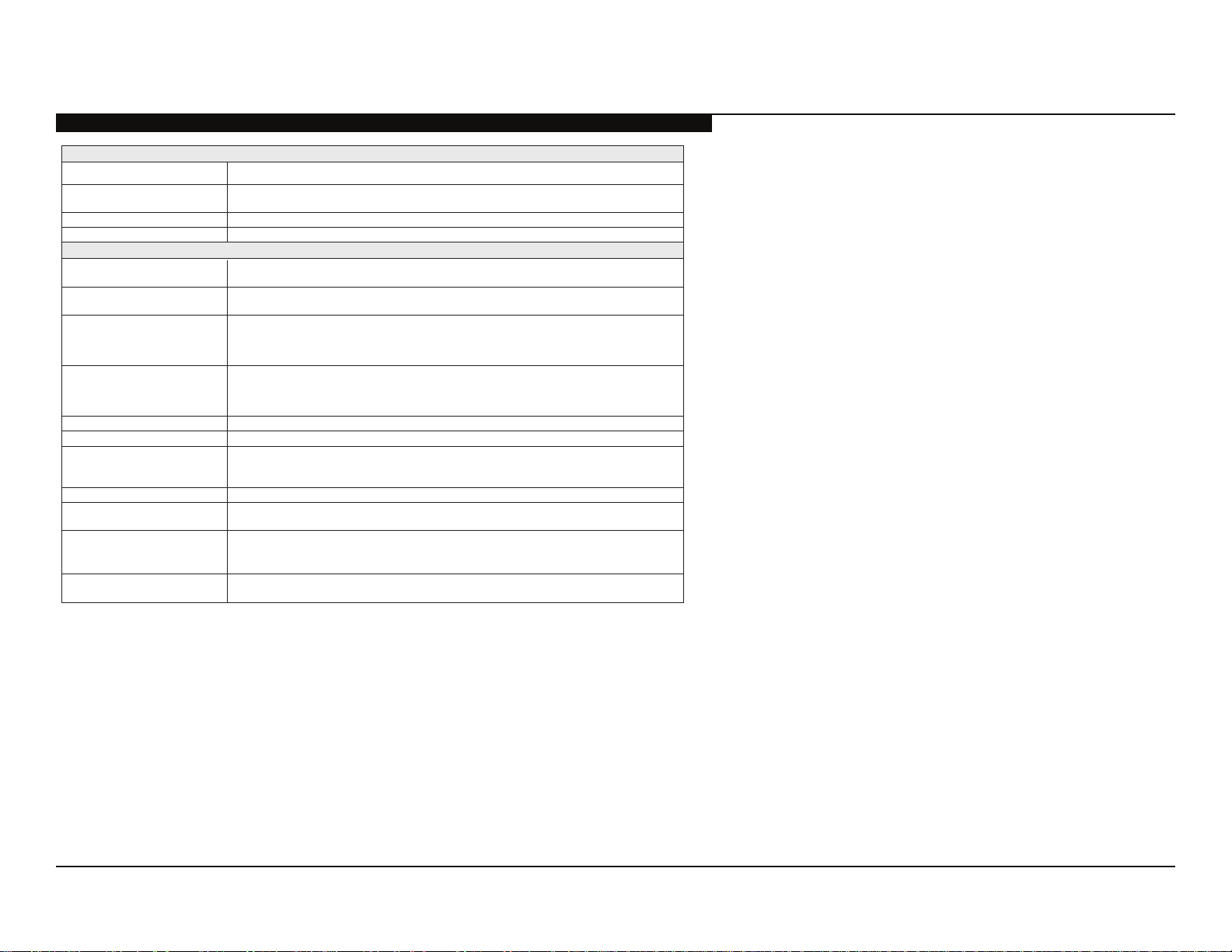
Nombre del modelo KDL-
Alimentación y otras especificaciones
Requisitos de alimentación 110 V -240 V ca, 50/60 Hz
Consumo energético
en uso
2
en DAM*
Tamaño de pantalla
(medido diagonalmente)
Bocina
Gama completa con parlantes (2)
Dimensiones con soporte
patrón de orificios de montaje mural
tamaño de tornillos de montaje mural
*2 El modo de adquisición de descarga (DAM) se utiliza para actualizaciones de software.
• La disponibilidad de los accesorios opcionales dependerá de las existencias.
• El diseño y las especificaciones están sujetos a cambios sin previo aviso.
(cm)
(pulgadas)
(mm)
052 × 536 × 299)mm(
(mm)
(mm)
46EX405 40EX406 40EX405
(Se puede oír un ruido durante la descarga pero es normal.)
116,8
46
541 × 54
1.127 × 711 × 294
1.127 × 674 × 102
M6 (longitud: consulte el diagrama de la página 15.)
ed selbaCselanoicpo soiroseccA conexión / Kit de correa de soporte / Soporte de montaje mural
W 51
300 × 300
32EX405
W 551W 971
W 2,0 ed soneMarepse ne
101,6
40
)lacitrev( saeníl 080.1 × )latnoziroh( sotnup 029.1 rotinom led nóiculoseR
45 × 130
001 × 895 × 299)mm(etropos nis
9,5120,4)gk( etropos nocoseP
9,311,81)gk( etropos nis
80,0
31,5 (32 clase)
200 × 200
32EX306
32EX305
W 311W 411
1.366 puntos (horizontal) ×
768 líneas (vertical)
022 × 235 × 008
79 × 794 × 008
0,11
5,9
Verificación de los accesorios
Cable de alimentación de ca (1)
(para modelos KDL-46EX405)
Soporte de sobremesa (1)*
Cómo fijar tornillos para el soporte de sobremesa (M5 × 16) (4)
Cómo montar tornillos para el soporte de sobremesa (M4 × 10) (3)
Control remoto (1)*
2
Pilas de tamaño AAA (2)
*1Los modelos de 32” (80,0 cm) y 40” (101, 6 cm) requieren montaje.
Consulte el otro folleto para ensamblar el soporte.
2
Consulte el nombre del modelo impreso en el control remoto.
*
KDL-32EX305/32EX306/32EX405/40EX405/40EX406/46EX405 2
1
WARNINGS AND CAUTIONS
CAUTION
These servicing instructions are for use by qualifi ed service personnel only. To reduce the risk of electric shock, do not perform any servicing
other than that contained in the operating instructions unless you are qualifi ed to do so.
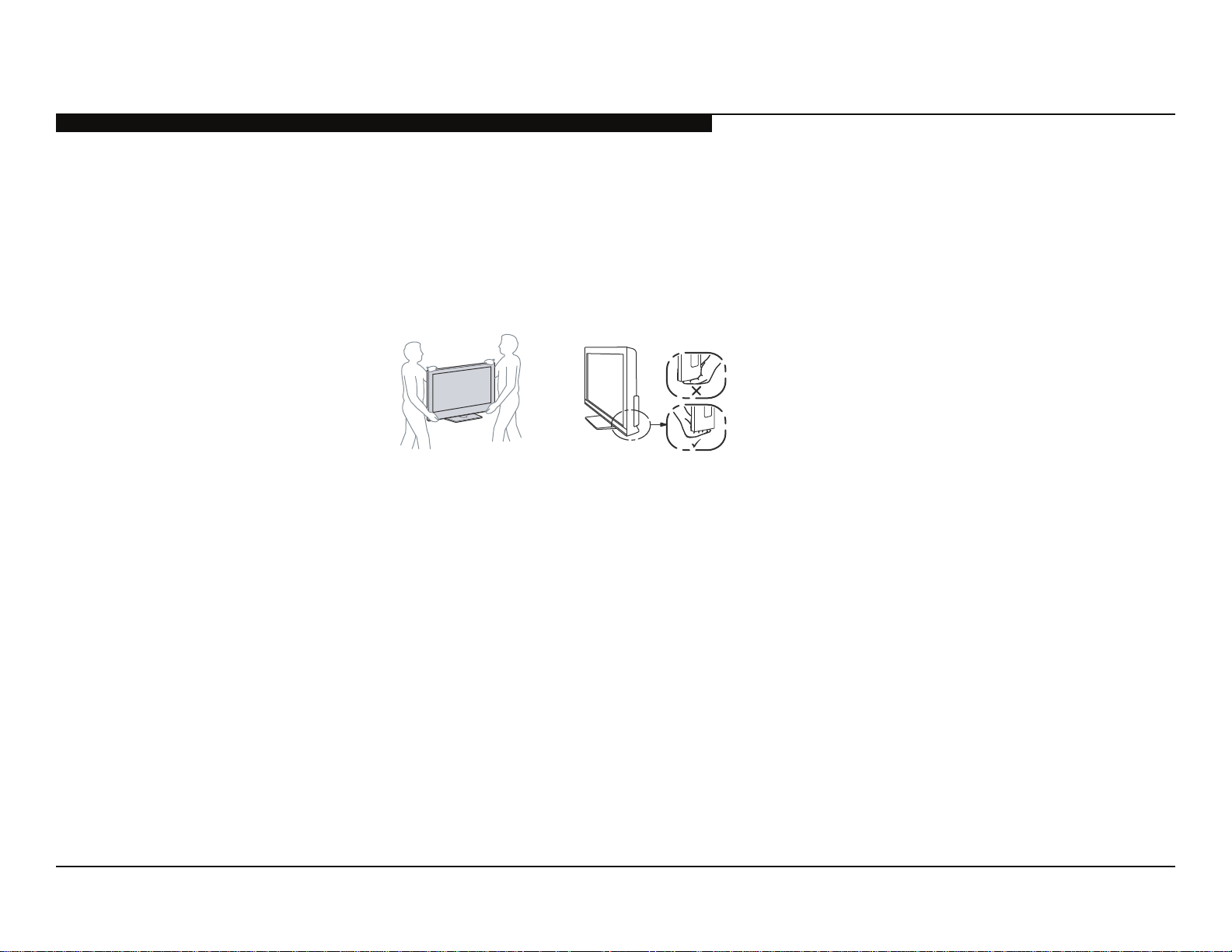
CARRYING THE TV
• Carry the TV with the adequate number of people; larger size TVs require two or more people.
• Correct hand placement while carrying the TV is very important for safety and to avoid
damage.
WARNING!!
An isolation transformer should be used during any service to avoid possible shock hazard, because of live chassis. The chassis of this
receiver is directly connected to the AC power line.
! SAFETY-RELATED COMPONENT WARNING!!
Components identifi ed by shading and ! mark on the exploded views are critical for safe operation.
Replace all components with Sony parts whose part numbers appear as shown in this manual or in supplements published by Sony. It is
essential that all critical parts be replaced only with the part number specifi ed in this manual to prevent electric shock, fi re, or other hazard.
Circuit adjustments that are critical for safe operation are identifi ed in this manual.
Follow these procedures whenever critical components are replaced or improper operation is suspected.
NOTE: Do not modify the original design without obtaining written permission from the manufacturer or you will void the original parts and
labor guarantee.
KDL-32EX305/32EX306/32EX405/40EX405/40EX406/46EX405 3

SAFETY-RELATED WARNING
USE CAUTION WHEN HANDLING THE LCD PANEL
When repairing the LCD panel, be sure you are grounded by using a wrist band.
When installing the LCD panel on a wall, the LCD panel must be secured using the 4 mounting holes on the rear cover.
1) Do not press on the panel or frame edge to avoid the risk of electric shock.
2) Do not scratch or press on the panel with any sharp objects.
3) Do not leave the module in high temperatures or in areas of high humidity for an extended period of time.
4) Do not expose the LCD panel to direct sunlight.
5) Avoid contact with water. It may cause a short circuit within the module.
6) Disconnect the AC power when replacing the backlight (CCFL) or inverter circuit.
(High voltage occurs at the inverter circuit at 650Vrms.)
7) Always clean the LCD panel with a soft cloth material.
8) Use care when handling the wires or connectors of the inverter circuit. Damaging the wires may cause a short.
9) Protect the panel from ESD to avoid damaging the electronic circuit (C-MOS).
KDL-32EX305/32EX306/32EX405/40EX405/40EX406/46EX405 4

SAFETY CHECK-OUT
After correcting the original service problem, perform the following safety checks before releasing the set to the customer:
1. Check the area of your repair for unsoldered or poorly soldered connections.
Check the entire board surface for solder splashes and bridges.
2. Check the interboard wiring to ensure that no wires are “pinched” or touching
high-wattage resistors.
3. Check that all control knobs, shields, covers, ground straps, and mounting
hardware have been replaced. Be absolutely certain that you have replaced
all the insulators.
4. Look for unauthorized replacement parts, particularly transistors, that were
installed during a previous repair. Point them out to the customer and
recommend their replacement.
0.15 μF
To Exposed Metal
Parts on Set
AC
Voltmeter
(0.75V)
5. Look for parts which, though functioning, show obvious signs of deterioration.
Point them out to the customer and recommend their replacement.
6. Check the line cords for cracks and abrasion. Recommend the replacement
of any such line cord to the customer.
7. Check the antenna terminals, metal trim, “metallized” knobs, screws, and
all other exposed metal parts for AC leakage. Check leakage as described
below.
Figure A. Using an AC voltmeter to check AC leakage.
Earth Ground
KDL-32EX305/32EX306/32EX405/40EX405/40EX406/46EX405 5
LEAKAGE TEST
The AC leakage from any exposed metal part to earth ground and from all
exposed metal parts to any exposed metal part having a return to chassis, must
not exceed 0.5 mA(500 microamperes). Leakage current can be measured by
any one of three methods.
1. A commercial leakage tester, such as the Simpson 229 or RCA WT-540A.
Follow the manufacturers’ instructions to use these instructions.
2. A battery-operated AC milliampmeter. The Data Precision 245 digital
multimeter is suitable for this job.
3. Measuring the voltage drop across a resistor by means of a VOM or batteryoperated AC voltmeter. The “limit” indication is 0.75 V, so analog meters
must have an accurate low voltage scale.
SAFETY CHECK-OUT
Trouble Light
AC Outlet Box
Ohmmeter
The Simpson’s 250 and Sanwa SH-63TRD are examples of passive VOMs
that are suitable. Nearly all battery-operated digital multimeters that have a
2 VAC range are suitable (see Figure A).
Cold-water Pipe
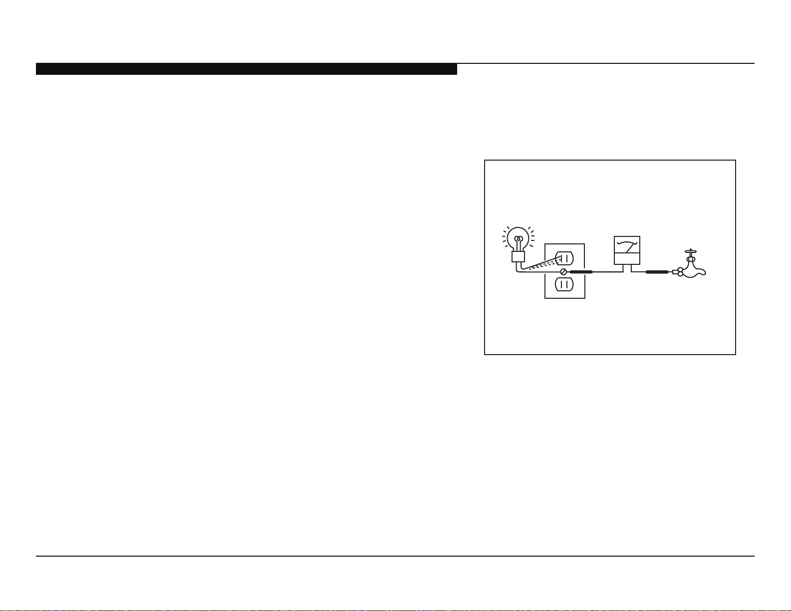
HOW TO FIND A GOOD EARTH GROUND
A cold-water pipe is a guaranteed earth ground; the cover-plate retaining screw
on most AC outlet boxes is also at earth ground.
If the retaining screw is to be used as your earth ground, verify that it is at
ground by measuring the resistance between it and a cold-water pipe with an
ohmmeter. The reading should be zero ohms.
If a cold-water pipe is not accessible, connect a 60-to 100-watt trouble-light (not
a neon lamp) between the hot side of the receptacle and the retaining screw.
Try both slots, if necessary, to locate the hot side on the line; the lamp should
light at normal brilliance if the screw is at ground potential (see Figure B).
KDL-32EX305/32EX306/32EX405/40EX405/40EX406/46EX405 6
Figure B. Checking for earth ground.
 Loading...